EP3572266B1 - Fahrzeug mit einer fahrzeugantriebsvorrichtung - Google Patents
Fahrzeug mit einer fahrzeugantriebsvorrichtung Download PDFInfo
- Publication number
- EP3572266B1 EP3572266B1 EP18822721.9A EP18822721A EP3572266B1 EP 3572266 B1 EP3572266 B1 EP 3572266B1 EP 18822721 A EP18822721 A EP 18822721A EP 3572266 B1 EP3572266 B1 EP 3572266B1
- Authority
- EP
- European Patent Office
- Prior art keywords
- motor
- vehicle
- housing
- linked
- vehicle body
- Prior art date
- Legal status (The legal status is an assumption and is not a legal conclusion. Google has not performed a legal analysis and makes no representation as to the accuracy of the status listed.)
- Active
Links
Images
Classifications
-
- B—PERFORMING OPERATIONS; TRANSPORTING
- B60—VEHICLES IN GENERAL
- B60K—ARRANGEMENT OR MOUNTING OF PROPULSION UNITS OR OF TRANSMISSIONS IN VEHICLES; ARRANGEMENT OR MOUNTING OF PLURAL DIVERSE PRIME-MOVERS IN VEHICLES; AUXILIARY DRIVES FOR VEHICLES; INSTRUMENTATION OR DASHBOARDS FOR VEHICLES; ARRANGEMENTS IN CONNECTION WITH COOLING, AIR INTAKE, GAS EXHAUST OR FUEL SUPPLY OF PROPULSION UNITS IN VEHICLES
- B60K17/00—Arrangement or mounting of transmissions in vehicles
- B60K17/04—Arrangement or mounting of transmissions in vehicles characterised by arrangement, location or kind of gearing
- B60K17/16—Arrangement or mounting of transmissions in vehicles characterised by arrangement, location or kind of gearing of differential gearing
- B60K17/165—Arrangement or mounting of transmissions in vehicles characterised by arrangement, location or kind of gearing of differential gearing provided between independent half axles
-
- B—PERFORMING OPERATIONS; TRANSPORTING
- B62—LAND VEHICLES FOR TRAVELLING OTHERWISE THAN ON RAILS
- B62D—MOTOR VEHICLES; TRAILERS
- B62D24/00—Connections between vehicle body and vehicle frame
- B62D24/04—Vehicle body mounted on resilient suspension for movement relative to the vehicle frame
-
- B—PERFORMING OPERATIONS; TRANSPORTING
- B60—VEHICLES IN GENERAL
- B60B—VEHICLE WHEELS; CASTORS; AXLES FOR WHEELS OR CASTORS; INCREASING WHEEL ADHESION
- B60B35/00—Axle units; Parts thereof ; Arrangements for lubrication of axles
- B60B35/12—Torque-transmitting axles
- B60B35/16—Axle housings
-
- B—PERFORMING OPERATIONS; TRANSPORTING
- B60—VEHICLES IN GENERAL
- B60B—VEHICLE WHEELS; CASTORS; AXLES FOR WHEELS OR CASTORS; INCREASING WHEEL ADHESION
- B60B35/00—Axle units; Parts thereof ; Arrangements for lubrication of axles
- B60B35/12—Torque-transmitting axles
- B60B35/18—Arrangement of bearings
-
- B—PERFORMING OPERATIONS; TRANSPORTING
- B60—VEHICLES IN GENERAL
- B60G—VEHICLE SUSPENSION ARRANGEMENTS
- B60G11/00—Resilient suspensions characterised by arrangement, location or kind of springs
- B60G11/02—Resilient suspensions characterised by arrangement, location or kind of springs having leaf springs only
- B60G11/04—Resilient suspensions characterised by arrangement, location or kind of springs having leaf springs only arranged substantially parallel to the longitudinal axis of the vehicle
-
- B—PERFORMING OPERATIONS; TRANSPORTING
- B60—VEHICLES IN GENERAL
- B60G—VEHICLE SUSPENSION ARRANGEMENTS
- B60G11/00—Resilient suspensions characterised by arrangement, location or kind of springs
- B60G11/02—Resilient suspensions characterised by arrangement, location or kind of springs having leaf springs only
- B60G11/10—Resilient suspensions characterised by arrangement, location or kind of springs having leaf springs only characterised by means specially adapted for attaching the spring to axle or sprung part of the vehicle
- B60G11/113—Mountings on the axle
-
- B—PERFORMING OPERATIONS; TRANSPORTING
- B60—VEHICLES IN GENERAL
- B60K—ARRANGEMENT OR MOUNTING OF PROPULSION UNITS OR OF TRANSMISSIONS IN VEHICLES; ARRANGEMENT OR MOUNTING OF PLURAL DIVERSE PRIME-MOVERS IN VEHICLES; AUXILIARY DRIVES FOR VEHICLES; INSTRUMENTATION OR DASHBOARDS FOR VEHICLES; ARRANGEMENTS IN CONNECTION WITH COOLING, AIR INTAKE, GAS EXHAUST OR FUEL SUPPLY OF PROPULSION UNITS IN VEHICLES
- B60K1/00—Arrangement or mounting of electrical propulsion units
-
- B—PERFORMING OPERATIONS; TRANSPORTING
- B60—VEHICLES IN GENERAL
- B60K—ARRANGEMENT OR MOUNTING OF PROPULSION UNITS OR OF TRANSMISSIONS IN VEHICLES; ARRANGEMENT OR MOUNTING OF PLURAL DIVERSE PRIME-MOVERS IN VEHICLES; AUXILIARY DRIVES FOR VEHICLES; INSTRUMENTATION OR DASHBOARDS FOR VEHICLES; ARRANGEMENTS IN CONNECTION WITH COOLING, AIR INTAKE, GAS EXHAUST OR FUEL SUPPLY OF PROPULSION UNITS IN VEHICLES
- B60K17/00—Arrangement or mounting of transmissions in vehicles
- B60K17/04—Arrangement or mounting of transmissions in vehicles characterised by arrangement, location or kind of gearing
- B60K17/16—Arrangement or mounting of transmissions in vehicles characterised by arrangement, location or kind of gearing of differential gearing
-
- B—PERFORMING OPERATIONS; TRANSPORTING
- B60—VEHICLES IN GENERAL
- B60K—ARRANGEMENT OR MOUNTING OF PROPULSION UNITS OR OF TRANSMISSIONS IN VEHICLES; ARRANGEMENT OR MOUNTING OF PLURAL DIVERSE PRIME-MOVERS IN VEHICLES; AUXILIARY DRIVES FOR VEHICLES; INSTRUMENTATION OR DASHBOARDS FOR VEHICLES; ARRANGEMENTS IN CONNECTION WITH COOLING, AIR INTAKE, GAS EXHAUST OR FUEL SUPPLY OF PROPULSION UNITS IN VEHICLES
- B60K17/00—Arrangement or mounting of transmissions in vehicles
- B60K17/04—Arrangement or mounting of transmissions in vehicles characterised by arrangement, location or kind of gearing
- B60K17/16—Arrangement or mounting of transmissions in vehicles characterised by arrangement, location or kind of gearing of differential gearing
- B60K17/18—Arrangement or mounting of transmissions in vehicles characterised by arrangement, location or kind of gearing of differential gearing in which the differential movement is obtained by resilient means
-
- B—PERFORMING OPERATIONS; TRANSPORTING
- B60—VEHICLES IN GENERAL
- B60K—ARRANGEMENT OR MOUNTING OF PROPULSION UNITS OR OF TRANSMISSIONS IN VEHICLES; ARRANGEMENT OR MOUNTING OF PLURAL DIVERSE PRIME-MOVERS IN VEHICLES; AUXILIARY DRIVES FOR VEHICLES; INSTRUMENTATION OR DASHBOARDS FOR VEHICLES; ARRANGEMENTS IN CONNECTION WITH COOLING, AIR INTAKE, GAS EXHAUST OR FUEL SUPPLY OF PROPULSION UNITS IN VEHICLES
- B60K5/00—Arrangement or mounting of internal-combustion or jet-propulsion units
- B60K5/12—Arrangement of engine supports
-
- B—PERFORMING OPERATIONS; TRANSPORTING
- B60—VEHICLES IN GENERAL
- B60K—ARRANGEMENT OR MOUNTING OF PROPULSION UNITS OR OF TRANSMISSIONS IN VEHICLES; ARRANGEMENT OR MOUNTING OF PLURAL DIVERSE PRIME-MOVERS IN VEHICLES; AUXILIARY DRIVES FOR VEHICLES; INSTRUMENTATION OR DASHBOARDS FOR VEHICLES; ARRANGEMENTS IN CONNECTION WITH COOLING, AIR INTAKE, GAS EXHAUST OR FUEL SUPPLY OF PROPULSION UNITS IN VEHICLES
- B60K5/00—Arrangement or mounting of internal-combustion or jet-propulsion units
- B60K5/12—Arrangement of engine supports
- B60K5/1208—Resilient supports
-
- B—PERFORMING OPERATIONS; TRANSPORTING
- B60—VEHICLES IN GENERAL
- B60K—ARRANGEMENT OR MOUNTING OF PROPULSION UNITS OR OF TRANSMISSIONS IN VEHICLES; ARRANGEMENT OR MOUNTING OF PLURAL DIVERSE PRIME-MOVERS IN VEHICLES; AUXILIARY DRIVES FOR VEHICLES; INSTRUMENTATION OR DASHBOARDS FOR VEHICLES; ARRANGEMENTS IN CONNECTION WITH COOLING, AIR INTAKE, GAS EXHAUST OR FUEL SUPPLY OF PROPULSION UNITS IN VEHICLES
- B60K5/00—Arrangement or mounting of internal-combustion or jet-propulsion units
- B60K5/12—Arrangement of engine supports
- B60K5/1208—Resilient supports
- B60K5/1216—Resilient supports characterised by the location of the supports relative to the motor or to each other
-
- B—PERFORMING OPERATIONS; TRANSPORTING
- B60—VEHICLES IN GENERAL
- B60G—VEHICLE SUSPENSION ARRANGEMENTS
- B60G2204/00—Indexing codes related to suspensions per se or to auxiliary parts
- B60G2204/10—Mounting of suspension elements
- B60G2204/19—Mounting of transmission differential
-
- B—PERFORMING OPERATIONS; TRANSPORTING
- B60—VEHICLES IN GENERAL
- B60L—PROPULSION OF ELECTRICALLY-PROPELLED VEHICLES; SUPPLYING ELECTRIC POWER FOR AUXILIARY EQUIPMENT OF ELECTRICALLY-PROPELLED VEHICLES; ELECTRODYNAMIC BRAKE SYSTEMS FOR VEHICLES IN GENERAL; MAGNETIC SUSPENSION OR LEVITATION FOR VEHICLES; MONITORING OPERATING VARIABLES OF ELECTRICALLY-PROPELLED VEHICLES; ELECTRIC SAFETY DEVICES FOR ELECTRICALLY-PROPELLED VEHICLES
- B60L2200/00—Type of vehicles
- B60L2200/36—Vehicles designed to transport cargo, e.g. trucks
-
- B—PERFORMING OPERATIONS; TRANSPORTING
- B60—VEHICLES IN GENERAL
- B60L—PROPULSION OF ELECTRICALLY-PROPELLED VEHICLES; SUPPLYING ELECTRIC POWER FOR AUXILIARY EQUIPMENT OF ELECTRICALLY-PROPELLED VEHICLES; ELECTRODYNAMIC BRAKE SYSTEMS FOR VEHICLES IN GENERAL; MAGNETIC SUSPENSION OR LEVITATION FOR VEHICLES; MONITORING OPERATING VARIABLES OF ELECTRICALLY-PROPELLED VEHICLES; ELECTRIC SAFETY DEVICES FOR ELECTRICALLY-PROPELLED VEHICLES
- B60L2270/00—Problem solutions or means not otherwise provided for
- B60L2270/10—Emission reduction
- B60L2270/14—Emission reduction of noise
- B60L2270/145—Structure borne vibrations
Definitions
- the present invention relates to a vehicle comprising a vehicle driving apparatus, and particularly a vehicle driving apparatus suitable for an electrically powered commercial car.
- Patent Literature 1 As a vehicle driving apparatus in the related art, there is a known driving unit in which a driving motor and a speed reducer are provided integrally with a differential gear (see Patent Literature 1, for example).
- An example of an axle structure that can handle the variety of car ranks may include a rigid axle structure using axle housings that accommodate the axles.
- Patent Literature US 4 560 027 A and US 4 564 082 A have already been used to produce such a vehicle driving apparatus having a driving unit housing that integrally accommodates a motor that drives a vehicle, a speed reducer that is linked to the motor, and a differential gear that is linked to the speed reducer.
- the apparatus comprising an axle housing to which a differential-side housing of the driving unit housing is linked and which integrally accommodates drive shafts of the driving wheels, a first support that allows a first rotary support shaft linked to a vehicle body of the vehicle to be elastically linked to the axle housing and the axle housing to swing around the first rotary support shaft as a center of rotation so that the axle housing is supported by the vehicle body; and a second support that allows a second rotary support shaft linked to the vehicle body of the vehicle to be elastically linked to a motor-side housing of the driving unit housing and the motor-side housing to swing around the second rotary support shaft as a center of rotation so that the motor-side housing is supported by the vehicle body.
- JP S50 8609 U discloses a drive system in which the motor, speed reducer, differential device and axle are integrally assembled, the axle is used as the vertical leaf spring of the vehicle body, and the motor is attached to the vehicle body via elastic bodies.
- the present invention has been made to solve at least part of the problem described above, and an object of the present invention is to provide a vehicle driving apparatus capable of handling a variety of car ranks and ensuring the reliability of a motor.
- the present invention has been made to solve at least part of the problem described above and can be achieved in the following aspects or application examples.
- the invention is defined by the subject-matter of the independent claim 1.
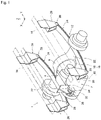
- FIG. 1 is a perspective view of a vehicle driving apparatus according to a first embodiment of the present invention.
- the vehicle driving apparatus 1 (hereinafter also simply referred to as driving apparatus) is incorporated in a rear section of an electrically powered commercial vehicle (hereinafter also referred to as vehicle), such as an electrically powered truck. It is noted that an obliquely lower side in FIG. 1 is the front side of the vehicle.
- a motor 2 as a driving source for travel is incorporated in the vehicle with a speed reducer 4 linked to the motor 2 and a differential 6 linked to the speed reducer 4.
- the driving force produced by the motor 2 is transmitted sequentially via the speed reducer 4, the differential 6, and a pair of drive shafts 8, which will be described later, to right and left wheels (driving wheels) 10, which will be described later.
- the wheels 10 are supported by respective side rails (vehicle body) 14, which extend via a suspension 12 in the vehicle frontward/rearward direction Y.
- the motor 2, the speed reducer 4, and the differential 6, which form the driving apparatus 1, are integrally accommodated in a driving unit housing 16.
- the driving unit housing 16 is generally formed of a differential-side housing 18, which accommodates the differential 6, a motor-side housing 20, which accommodates the motor 2 and the speed reducer 4, and a pair of axle housings 22, which accommodate a pair of drive shafts 8 in an integrated manner.
- the differential-side housing 18 is linked to the motor-side housing 20, specifically, the rear side thereof in the vehicle frontward/rearward direction Y, and the pair of axle housings 22 are linked to the differential-side housing 18, specifically, the opposite sides thereof in the vehicle width direction X.
- the suspension 12 is formed of the pair of axel housings 22, a pair of leaf springs 24, and other components, which form a rigid axle structure.
- the pair of leaf springs 24 extend in the vehicle frontward/rearward direction Y, and the opposite ends of each of the leaf springs 24 are suspended by the corresponding side rail 14 via first brackets (first supports) 26.
- the axle housings 22 are suspended by the respective leaf springs 24.
- the wheels 10 are thus elastically supported by the respective leaf springs 24.
- first hinge pin first rotary support shaft
- second bracket second support
- the opposite ends of the leaf springs 24 are each rotatably linked to the corresponding first bracket 26 via a first hinge pin (first rotary support shaft) 28.
- a second bracket (second support) 30 is fixed to a front portion of the motor-side housing 20.
- the second bracket 30 is so linked to a third bracket 34 as to be rotatable relative thereto via a second hinge pin (second rotary support shaft) 32.
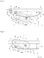
- FIG. 2 is a side view diagrammatically showing a structure that supports the driving apparatus 1.
- Cross members (vehicle body) 36 are located between the side rails and fixed thereto.
- the third bracket 34 is fixed to the cross members 36.
- Two reduction gears 38, which are linked to the motor 2, and a differential gear 40, which is linked to one of the reduction gears 38, are accommodated in the driving unit housing 16.
- the third bracket 34 may instead be fixed to the cross members 36 via hinge pins.
- the first hinge pin 28, which is provided in each of the first brackets 26, is inserted into a pin hole of the first bracket 26 via a rubber bush 46.
- the second hinge pin 32 which is provided in each of the second brackets 30, is inserted into a pin hole of the third bracket 34 via a rubber bush 48.
- the non-suspended support undesirably increases the magnitude of vibration inputted to the motor 2 incorporated as part of the driving apparatus 1.
- an electromagnetic coil is densely arranged, and the rotor rotates at high speed with the clearance between the electromagnetic coil and the inner wall of the motor-side housing 20 maintained at about several millimeters. Therefore, if large vibration resulting from a large magnitude of vibration inputted to the motor 2 causes the electromagnetic coil to come into contact and interfere with the inner wall of the motor-side housing 20, the reliability of the motor 2 could undesirably decrease.
- a front portion of the motor-side housing 20 is supported by the vehicle body via the second and third brackets 30, 34, so that at least the front portion of the motor-side housing 20 is directly suspended by the side rails 14 to achieve suspended support.
- the magnitude of the vibration inputted to the motor 2 can be reduced nearly to about 1/10 the magnitude of the vibration inputted to the entire driving apparatus 1 and hence the entire driving unit housing 16.
- the rigid axle structure can therefore be used to handle a variety of car ranks and ensure the reliability of the motor 2.
- the driving unit housing 16 primarily swings around the pin centers C of the first hinge pins 28 provided in the first brackets 26 that support the leaf springs 24 on the front side of the vehicle. Specifically, the driving unit housing 16 primarily swings around the pin centers C along a swing path T, which passes through the saddles 42, on which the leaf springs 24 are placed.
- the vibration of the driving unit housing 16 resulting from the swing motion thereof along the swing path T propagates, to no small extent, to the motor-side housing 20 and hence the motor 2.
- the driving unit housing 16 may be so disposed that the motor shaft 50 of the motor 2 is higher than the lowest surfaces of the leaf springs 24 in the vehicle height direction Z, as shown in FIG. 2 .
- the second bracket 30 and the second hinge pin 32 may be so disposed that the motor shaft 50 of the motor 2 is higher than the axis of rotation of the differential gear 40.
- the magnitude of the vibration that propagates to the motor 2 can thus be further reduced, whereby the reliability of the motor 2 can be further effectively ensured.
- the motor shaft 50 is allowed to be close to or coincide with the pin centers C of the first hinge pins 28 by in-advance consideration of the positions of the first and second brackets 26, 30 and the layout of the motor 2 in the structure that supports the driving unit housing 16.
- FIG. 3 is a side view diagrammatically showing a structure that supports the vehicle driving apparatus according to a second embodiment of the present invention. The same configurations as those in the first embodiment will not be described.
- An elastic support that forms the suspension 12 may be formed of a combination of the leaf springs 24 and air springs 52, as shown in FIG. 3 .
- the air springs 52 are each disposed between one end of the corresponding leaf spring 24 and the corresponding side rail 14.
- the motor-side housing 20 of the driving unit housing 16 is rotatably supported by the vehicle body via a hinge pin and a bracket that are not shown, and the differential-side housing 18 of the driving unit housing 16 is supported on the upper surfaces of the leaf springs 24 via support areas, which are not shown, of the axle housings 22.
- the entire driving unit housing 16 is allowed to swing while being supported by the leaf springs 24 and further allowed to move upward and downward while being supported by the air springs 52. Even in this case, since at least a front portion of the motor-side housing 20 can be directly suspended by the side rails 14 to achieve suspended support, the magnitude of the vibration inputted to the motor 2 can be reduced.
- the rigid axle structure can therefore be used to handle a variety of car ranks and ensure the reliability of the motor 2.
- the reliability of the motor 2 can further effectively ensured by minimizing the distance D between the center of the motor shaft 50 of the motor 2 and the pin centers C of the first hinge pins so that the motor shaft 50 is close to or coincides with the pin centers C of the first hinge pins 28.
- the axle housings 22 are supported by the vehicle body with the axle housings 22 swinging around the first hinge pins 28 as the center of rotation in the first bracket 26, whereas the motor-side housing 20 is supported by the vehicle body with the motor-side housing 20 swinging around the second hinge pin 32 as the center of rotation in the second bracket 30.
- the structure that supports the driving apparatus 1 is not limited to the exact forms in the first and second embodiments, and at least a front portion of the motor-side housing 20 only needs to be supported in a suspended manner.
- the driving unit housing 16 swings not only along the swing path T described above but around the pin center of the second hinge pin 32.
- the difference between the latter swing path and the swing path T described above is absorbed by the rubber plate 44 and the rubber bushes 46 and 48.
- Torsion of the vehicle body in the direction of rolling is also absorbed as appropriate by the rubber plate 44 and the rubber bushes 46 and 48.
- the magnitude of the vibration inputted to the motor 2 can therefore be further reduced, whereby the reliability of the motor 2 can further be effectively ensured.
- the driving apparatus 1 can, of course, be used in a variety of vehicles including passenger cars as well as electrically powered commercial cars, such as electrically powered trucks.
Landscapes
- Engineering & Computer Science (AREA)
- Mechanical Engineering (AREA)
- Chemical & Material Sciences (AREA)
- Combustion & Propulsion (AREA)
- Transportation (AREA)
- Arrangement Or Mounting Of Propulsion Units For Vehicles (AREA)
- Vehicle Body Suspensions (AREA)
- Motor Power Transmission Devices (AREA)
- Electric Propulsion And Braking For Vehicles (AREA)
- Vibration Prevention Devices (AREA)
Claims (3)
- Fahrzeug mit einer Fahrzeugkarosserie, wobei die Fahrzeugkarosserie zwei Seitenschienen (14) umfasst, und einer Fahrzeugantriebsvorrichtung (1), die umfasst:ein Antriebseinheitsgehäuse (16), das integral einen Motor (2), der ein Fahrzeug antreibt, ein Untersetzungsgetriebe (4), das mit dem Motor (2) verbunden ist, und ein Differentialgetriebe (6, 40), das mit dem Untersetzungsgetriebe (4) verbunden ist und eine durch den Motor (2) erzeugte Antriebskraft zu Antriebsrädern (10) des Fahrzeugs überträgt, aufnimmt;ein Achsgehäuse (22), mit dem ein Differentialseitengehäuse (18) des Antriebseinheitsgehäuses (16) verbunden ist und das integral Antriebswellen (8) der Antriebsräder (10) aufnimmt;einen ersten Träger (26), der ermöglicht, dass eine erste Drehstützwelle (28), die mit einer Fahrzeugkarosserie des Fahrzeugs verbunden ist, mit dem Achsgehäuse (22) elastisch verbunden ist und das Achsgehäuse (22) um die erste Drehstützwelle (28) als Drehzentrum schwenkt, so dass das Achsgehäuse (22) durch die Fahrzeugkarosserie abgestützt ist; undeinen zweiten Träger (30), der ermöglicht, dass eine zweite Drehstützwelle (32), die mit der Fahrzeugkarosserie des Fahrzeug verbunden ist, mit einem Motorseitengehäuse (20) des Antriebseinheitsgehäuses (16) elastisch verbunden ist und das Motorseitengehäuse (20) um die zweite Drehstützwelle (32) als Drehzentrum schwenkt, so dass das Motorseitengehäuse (20) durch die Fahrzeugkarosserie abgestützt ist, der zweite Träger (30) so angeordnet ist, dass eine Motorwelle (50) des Motors (2) in einer Fahrzeughöhenrichtung höher liegt als eine Drehachse des Differentialgetriebes (40), die im Wesentlichen in derselben Richtung wie die Motorwelle (50) orientiert ist;dadurch gekennzeichnet, dassein Paar von Blattfedern (24) sich in der Fahrzeug-Vorwärts-RückwärtsRichtung erstreckt, wobei die entgegengesetzten Enden von jeder der Blattfedern (24) durch die entsprechende Seitenschiene 14 über erste Träger (26) aufgehängt sind, und wobei die Achsgehäuse (22) durch die jeweiligen Blattfedern (24) aufgehängt sind.
- Fahrzeug nach Anspruch 1, wobei das Antriebseinheitsgehäuse (16) so abgestützt ist, dass eine Motorwelle (50) des Motors (2) nahe dem Drehzentrum der ersten Drehstützwelle (28) liegt.
- Fahrzeug nach einem der Ansprüche 1 bis 2, wobei der zweite Träger (30) an einem vorderen Teil des Motorseitengehäuses (20) befestigt ist und wobei der zweite Halter (30) so mit einem dritten Halter (34) verbunden ist, dass er relativ zu diesem über eine zweite Drehstützwelle (32) drehbar ist.
Applications Claiming Priority (2)
| Application Number | Priority Date | Filing Date | Title |
|---|---|---|---|
| JP2017128452A JP6793095B2 (ja) | 2017-06-30 | 2017-06-30 | 車両用駆動装置 |
| PCT/JP2018/017532 WO2019003633A1 (ja) | 2017-06-30 | 2018-05-02 | 車両用駆動装置 |
Publications (3)
| Publication Number | Publication Date |
|---|---|
| EP3572266A1 EP3572266A1 (de) | 2019-11-27 |
| EP3572266A4 EP3572266A4 (de) | 2021-01-27 |
| EP3572266B1 true EP3572266B1 (de) | 2022-10-19 |
Family
ID=64741413
Family Applications (1)
| Application Number | Title | Priority Date | Filing Date |
|---|---|---|---|
| EP18822721.9A Active EP3572266B1 (de) | 2017-06-30 | 2018-05-02 | Fahrzeug mit einer fahrzeugantriebsvorrichtung |
Country Status (5)
| Country | Link |
|---|---|
| US (1) | US20200156707A1 (de) |
| EP (1) | EP3572266B1 (de) |
| JP (1) | JP6793095B2 (de) |
| CN (1) | CN110431033A (de) |
| WO (1) | WO2019003633A1 (de) |
Families Citing this family (7)
| Publication number | Priority date | Publication date | Assignee | Title |
|---|---|---|---|---|
| WO2019200272A1 (en) * | 2018-04-13 | 2019-10-17 | Dana Heavy Vehicle Systems Group, Llc | Support apparatus for an off-axle load |
| JP2019189171A (ja) * | 2018-04-27 | 2019-10-31 | ダイムラー・アクチェンゲゼルシャフトDaimler AG | 駆動ユニット支持装置 |
| KR102777765B1 (ko) * | 2019-12-03 | 2025-03-07 | 현대자동차주식회사 | 전기 차량의 구동 시스템 |
| US11701956B2 (en) * | 2020-10-01 | 2023-07-18 | GM Global Technology Operations LLC | Axle including a drive system for an electric vehicle |
| JP7535020B2 (ja) | 2021-07-29 | 2024-08-15 | ダイムラー トラック エージー | 電動車両 |
| EP4527654A1 (de) * | 2023-09-25 | 2025-03-26 | Scania CV AB | Elektrische antriebsachsenanordnung und fahrzeug mit der elektrischen antriebsachsenanordnung |
| WO2025186959A1 (ja) * | 2024-03-06 | 2025-09-12 | 三菱自動車工業株式会社 | 車両の回転機取付構造 |
Family Cites Families (7)
| Publication number | Priority date | Publication date | Assignee | Title |
|---|---|---|---|---|
| GB781455A (en) * | 1952-07-09 | 1957-08-21 | Salzmann Willi Ernst | Improvements in or relating to the springing and suspension of vehicles |
| JPS508609A (de) * | 1973-06-01 | 1975-01-29 | ||
| JPS508609U (de) * | 1973-05-21 | 1975-01-29 | ||
| JPS5940946A (ja) * | 1982-09-01 | 1984-03-06 | Nissan Motor Co Ltd | 車両用パワ−ユニツトの支持構造 |
| JPS5989225A (ja) * | 1982-11-09 | 1984-05-23 | Nissan Motor Co Ltd | パワ−ユニツトの支持構造 |
| JP5952002B2 (ja) * | 2012-01-23 | 2016-07-13 | Ntn株式会社 | 車輪駆動装置 |
| EP2977251A1 (de) | 2013-03-18 | 2016-01-27 | Hitachi Automotive Systems, Ltd. | Antriebsvorrichtung für ein elektrofahrzeug |
-
2017
- 2017-06-30 JP JP2017128452A patent/JP6793095B2/ja active Active
-
2018
- 2018-05-02 WO PCT/JP2018/017532 patent/WO2019003633A1/ja not_active Ceased
- 2018-05-02 US US16/625,952 patent/US20200156707A1/en not_active Abandoned
- 2018-05-02 EP EP18822721.9A patent/EP3572266B1/de active Active
- 2018-05-02 CN CN201880018716.0A patent/CN110431033A/zh active Pending
Also Published As
| Publication number | Publication date |
|---|---|
| CN110431033A (zh) | 2019-11-08 |
| JP6793095B2 (ja) | 2020-12-02 |
| EP3572266A4 (de) | 2021-01-27 |
| JP2019010946A (ja) | 2019-01-24 |
| US20200156707A1 (en) | 2020-05-21 |
| WO2019003633A1 (ja) | 2019-01-03 |
| EP3572266A1 (de) | 2019-11-27 |
Similar Documents
| Publication | Publication Date | Title |
|---|---|---|
| EP3572266B1 (de) | Fahrzeug mit einer fahrzeugantriebsvorrichtung | |
| CN111032396A (zh) | 车辆用驱动装置 | |
| US10065663B2 (en) | Steering bogie and vehicle | |
| JP6703965B2 (ja) | 電動トラックの駆動装置 | |
| EP1724130B1 (de) | Konsole für eine Luftfeder | |
| WO2012137257A1 (ja) | 鉄道車両用台車 | |
| GB2491334A (en) | Electric traction motor drive assembly for a rail vehicle | |
| JPWO2006030532A1 (ja) | 電気自動車の駆動装置 | |
| JP6004996B2 (ja) | 鉄道車両用台車 | |
| EP4105050B1 (de) | Antriebsachsensystem | |
| JP5219718B2 (ja) | インホイールモータシステム | |
| CN108025754A (zh) | 用于轨道车辆的驱动组件,具有驱动组件的轨道车辆和制造方法 | |
| US20250050696A1 (en) | Vehicle | |
| WO2016181795A1 (ja) | インホイールモータ駆動装置用サスペンション構造 | |
| CN112298248A (zh) | 用于轨道车辆的转向架、轨道车辆和轨道交通系统 | |
| JP2017001407A (ja) | インホイールモータ駆動装置用サスペンション構造 | |
| JP2019043275A (ja) | 車両用駆動装置 | |
| EP3176048B1 (de) | Drehgestell für walzgut und walzgut damit | |
| CN113968256A (zh) | 转向架及轨道车辆 | |
| US12600214B2 (en) | Vehicle motor | |
| JP2021028182A (ja) | 車両用駆動装置 | |
| JPS6226944B2 (de) | ||
| JPH10138726A (ja) | 後二軸車の後軸懸架装置 | |
| KR20260011486A (ko) | 차량용 구동장치 | |
| CN113968255A (zh) | 转向架及轨道车辆 |
Legal Events
| Date | Code | Title | Description |
|---|---|---|---|
| STAA | Information on the status of an ep patent application or granted ep patent |
Free format text: STATUS: THE INTERNATIONAL PUBLICATION HAS BEEN MADE |
|
| PUAI | Public reference made under article 153(3) epc to a published international application that has entered the european phase |
Free format text: ORIGINAL CODE: 0009012 |
|
| STAA | Information on the status of an ep patent application or granted ep patent |
Free format text: STATUS: REQUEST FOR EXAMINATION WAS MADE |
|
| 17P | Request for examination filed |
Effective date: 20190820 |
|
| AK | Designated contracting states |
Kind code of ref document: A1 Designated state(s): AL AT BE BG CH CY CZ DE DK EE ES FI FR GB GR HR HU IE IS IT LI LT LU LV MC MK MT NL NO PL PT RO RS SE SI SK SM TR |
|
| AX | Request for extension of the european patent |
Extension state: BA ME |
|
| DAV | Request for validation of the european patent (deleted) | ||
| DAX | Request for extension of the european patent (deleted) | ||
| A4 | Supplementary search report drawn up and despatched |
Effective date: 20210114 |
|
| RIC1 | Information provided on ipc code assigned before grant |
Ipc: B60K 5/12 20060101ALI20201223BHEP Ipc: B60K 1/00 20060101ALI20201223BHEP Ipc: B60B 35/16 20060101ALI20201223BHEP Ipc: B60K 17/16 20060101AFI20201223BHEP Ipc: B60L 15/00 20060101ALI20201223BHEP |
|
| STAA | Information on the status of an ep patent application or granted ep patent |
Free format text: STATUS: EXAMINATION IS IN PROGRESS |
|
| 17Q | First examination report despatched |
Effective date: 20211118 |
|
| RIC1 | Information provided on ipc code assigned before grant |
Ipc: B60G 11/04 20060101ALN20220331BHEP Ipc: B60G 11/113 20060101ALN20220331BHEP Ipc: B60K 5/12 20060101ALN20220331BHEP Ipc: B60B 35/16 20060101ALN20220331BHEP Ipc: B60L 15/00 20060101ALN20220331BHEP Ipc: B60K 1/00 20060101ALI20220331BHEP Ipc: B60K 17/16 20060101AFI20220331BHEP |
|
| GRAP | Despatch of communication of intention to grant a patent |
Free format text: ORIGINAL CODE: EPIDOSNIGR1 |
|
| STAA | Information on the status of an ep patent application or granted ep patent |
Free format text: STATUS: GRANT OF PATENT IS INTENDED |
|
| INTG | Intention to grant announced |
Effective date: 20220510 |
|
| GRAS | Grant fee paid |
Free format text: ORIGINAL CODE: EPIDOSNIGR3 |
|
| GRAA | (expected) grant |
Free format text: ORIGINAL CODE: 0009210 |
|
| STAA | Information on the status of an ep patent application or granted ep patent |
Free format text: STATUS: THE PATENT HAS BEEN GRANTED |
|
| AK | Designated contracting states |
Kind code of ref document: B1 Designated state(s): AL AT BE BG CH CY CZ DE DK EE ES FI FR GB GR HR HU IE IS IT LI LT LU LV MC MK MT NL NO PL PT RO RS SE SI SK SM TR |
|
| REG | Reference to a national code |
Ref country code: GB Ref legal event code: FG4D |
|
| REG | Reference to a national code |
Ref country code: CH Ref legal event code: EP |
|
| REG | Reference to a national code |
Ref country code: IE Ref legal event code: FG4D |
|
| REG | Reference to a national code |
Ref country code: DE Ref legal event code: R096 Ref document number: 602018042048 Country of ref document: DE |
|
| REG | Reference to a national code |
Ref country code: AT Ref legal event code: REF Ref document number: 1525367 Country of ref document: AT Kind code of ref document: T Effective date: 20221115 |
|
| REG | Reference to a national code |
Ref country code: LT Ref legal event code: MG9D |
|
| REG | Reference to a national code |
Ref country code: NL Ref legal event code: MP Effective date: 20221019 |
|
| REG | Reference to a national code |
Ref country code: AT Ref legal event code: MK05 Ref document number: 1525367 Country of ref document: AT Kind code of ref document: T Effective date: 20221019 |
|
| PG25 | Lapsed in a contracting state [announced via postgrant information from national office to epo] |
Ref country code: NL Free format text: LAPSE BECAUSE OF FAILURE TO SUBMIT A TRANSLATION OF THE DESCRIPTION OR TO PAY THE FEE WITHIN THE PRESCRIBED TIME-LIMIT Effective date: 20221019 |
|
| PG25 | Lapsed in a contracting state [announced via postgrant information from national office to epo] |
Ref country code: SE Free format text: LAPSE BECAUSE OF FAILURE TO SUBMIT A TRANSLATION OF THE DESCRIPTION OR TO PAY THE FEE WITHIN THE PRESCRIBED TIME-LIMIT Effective date: 20221019 Ref country code: PT Free format text: LAPSE BECAUSE OF FAILURE TO SUBMIT A TRANSLATION OF THE DESCRIPTION OR TO PAY THE FEE WITHIN THE PRESCRIBED TIME-LIMIT Effective date: 20230220 Ref country code: NO Free format text: LAPSE BECAUSE OF FAILURE TO SUBMIT A TRANSLATION OF THE DESCRIPTION OR TO PAY THE FEE WITHIN THE PRESCRIBED TIME-LIMIT Effective date: 20230119 Ref country code: LT Free format text: LAPSE BECAUSE OF FAILURE TO SUBMIT A TRANSLATION OF THE DESCRIPTION OR TO PAY THE FEE WITHIN THE PRESCRIBED TIME-LIMIT Effective date: 20221019 Ref country code: FI Free format text: LAPSE BECAUSE OF FAILURE TO SUBMIT A TRANSLATION OF THE DESCRIPTION OR TO PAY THE FEE WITHIN THE PRESCRIBED TIME-LIMIT Effective date: 20221019 Ref country code: ES Free format text: LAPSE BECAUSE OF FAILURE TO SUBMIT A TRANSLATION OF THE DESCRIPTION OR TO PAY THE FEE WITHIN THE PRESCRIBED TIME-LIMIT Effective date: 20221019 Ref country code: AT Free format text: LAPSE BECAUSE OF FAILURE TO SUBMIT A TRANSLATION OF THE DESCRIPTION OR TO PAY THE FEE WITHIN THE PRESCRIBED TIME-LIMIT Effective date: 20221019 |
|
| PG25 | Lapsed in a contracting state [announced via postgrant information from national office to epo] |
Ref country code: RS Free format text: LAPSE BECAUSE OF FAILURE TO SUBMIT A TRANSLATION OF THE DESCRIPTION OR TO PAY THE FEE WITHIN THE PRESCRIBED TIME-LIMIT Effective date: 20221019 Ref country code: PL Free format text: LAPSE BECAUSE OF FAILURE TO SUBMIT A TRANSLATION OF THE DESCRIPTION OR TO PAY THE FEE WITHIN THE PRESCRIBED TIME-LIMIT Effective date: 20221019 Ref country code: LV Free format text: LAPSE BECAUSE OF FAILURE TO SUBMIT A TRANSLATION OF THE DESCRIPTION OR TO PAY THE FEE WITHIN THE PRESCRIBED TIME-LIMIT Effective date: 20221019 Ref country code: IS Free format text: LAPSE BECAUSE OF FAILURE TO SUBMIT A TRANSLATION OF THE DESCRIPTION OR TO PAY THE FEE WITHIN THE PRESCRIBED TIME-LIMIT Effective date: 20230219 Ref country code: HR Free format text: LAPSE BECAUSE OF FAILURE TO SUBMIT A TRANSLATION OF THE DESCRIPTION OR TO PAY THE FEE WITHIN THE PRESCRIBED TIME-LIMIT Effective date: 20221019 Ref country code: GR Free format text: LAPSE BECAUSE OF FAILURE TO SUBMIT A TRANSLATION OF THE DESCRIPTION OR TO PAY THE FEE WITHIN THE PRESCRIBED TIME-LIMIT Effective date: 20230120 |
|
| P01 | Opt-out of the competence of the unified patent court (upc) registered |
Effective date: 20230601 |
|
| REG | Reference to a national code |
Ref country code: DE Ref legal event code: R097 Ref document number: 602018042048 Country of ref document: DE |
|
| PG25 | Lapsed in a contracting state [announced via postgrant information from national office to epo] |
Ref country code: SM Free format text: LAPSE BECAUSE OF FAILURE TO SUBMIT A TRANSLATION OF THE DESCRIPTION OR TO PAY THE FEE WITHIN THE PRESCRIBED TIME-LIMIT Effective date: 20221019 Ref country code: RO Free format text: LAPSE BECAUSE OF FAILURE TO SUBMIT A TRANSLATION OF THE DESCRIPTION OR TO PAY THE FEE WITHIN THE PRESCRIBED TIME-LIMIT Effective date: 20221019 Ref country code: EE Free format text: LAPSE BECAUSE OF FAILURE TO SUBMIT A TRANSLATION OF THE DESCRIPTION OR TO PAY THE FEE WITHIN THE PRESCRIBED TIME-LIMIT Effective date: 20221019 Ref country code: DK Free format text: LAPSE BECAUSE OF FAILURE TO SUBMIT A TRANSLATION OF THE DESCRIPTION OR TO PAY THE FEE WITHIN THE PRESCRIBED TIME-LIMIT Effective date: 20221019 Ref country code: CZ Free format text: LAPSE BECAUSE OF FAILURE TO SUBMIT A TRANSLATION OF THE DESCRIPTION OR TO PAY THE FEE WITHIN THE PRESCRIBED TIME-LIMIT Effective date: 20221019 |
|
| PLBE | No opposition filed within time limit |
Free format text: ORIGINAL CODE: 0009261 |
|
| STAA | Information on the status of an ep patent application or granted ep patent |
Free format text: STATUS: NO OPPOSITION FILED WITHIN TIME LIMIT |
|
| PG25 | Lapsed in a contracting state [announced via postgrant information from national office to epo] |
Ref country code: SK Free format text: LAPSE BECAUSE OF FAILURE TO SUBMIT A TRANSLATION OF THE DESCRIPTION OR TO PAY THE FEE WITHIN THE PRESCRIBED TIME-LIMIT Effective date: 20221019 Ref country code: AL Free format text: LAPSE BECAUSE OF FAILURE TO SUBMIT A TRANSLATION OF THE DESCRIPTION OR TO PAY THE FEE WITHIN THE PRESCRIBED TIME-LIMIT Effective date: 20221019 |
|
| 26N | No opposition filed |
Effective date: 20230720 |
|
| REG | Reference to a national code |
Ref country code: DE Ref legal event code: R081 Ref document number: 602018042048 Country of ref document: DE Owner name: DAIMLER TRUCK AG, DE Free format text: FORMER OWNER: DAIMLER AG, 70372 STUTTGART, DE Ref country code: DE Ref legal event code: R082 Ref document number: 602018042048 Country of ref document: DE Ref country code: DE Ref legal event code: R082 Ref document number: 602018042048 Country of ref document: DE Representative=s name: HOFSTETTER, SCHURACK & PARTNER - PATENT- UND R, DE |
|
| PG25 | Lapsed in a contracting state [announced via postgrant information from national office to epo] |
Ref country code: SI Free format text: LAPSE BECAUSE OF FAILURE TO SUBMIT A TRANSLATION OF THE DESCRIPTION OR TO PAY THE FEE WITHIN THE PRESCRIBED TIME-LIMIT Effective date: 20221019 |
|
| REG | Reference to a national code |
Ref country code: CH Ref legal event code: PL |
|
| PG25 | Lapsed in a contracting state [announced via postgrant information from national office to epo] |
Ref country code: MC Free format text: LAPSE BECAUSE OF FAILURE TO SUBMIT A TRANSLATION OF THE DESCRIPTION OR TO PAY THE FEE WITHIN THE PRESCRIBED TIME-LIMIT Effective date: 20221019 |
|
| REG | Reference to a national code |
Ref country code: BE Ref legal event code: MM Effective date: 20230531 |
|
| PG25 | Lapsed in a contracting state [announced via postgrant information from national office to epo] |
Ref country code: MC Free format text: LAPSE BECAUSE OF FAILURE TO SUBMIT A TRANSLATION OF THE DESCRIPTION OR TO PAY THE FEE WITHIN THE PRESCRIBED TIME-LIMIT Effective date: 20221019 Ref country code: LU Free format text: LAPSE BECAUSE OF NON-PAYMENT OF DUE FEES Effective date: 20230502 Ref country code: LI Free format text: LAPSE BECAUSE OF NON-PAYMENT OF DUE FEES Effective date: 20230531 Ref country code: CH Free format text: LAPSE BECAUSE OF NON-PAYMENT OF DUE FEES Effective date: 20230531 |
|
| REG | Reference to a national code |
Ref country code: IE Ref legal event code: MM4A |
|
| REG | Reference to a national code |
Ref country code: DE Ref legal event code: R082 Ref document number: 602018042048 Country of ref document: DE Representative=s name: HOFSTETTER, SCHURACK & PARTNER - PATENT- UND R, DE |
|
| PG25 | Lapsed in a contracting state [announced via postgrant information from national office to epo] |
Ref country code: IE Free format text: LAPSE BECAUSE OF NON-PAYMENT OF DUE FEES Effective date: 20230502 |
|
| PG25 | Lapsed in a contracting state [announced via postgrant information from national office to epo] |
Ref country code: IE Free format text: LAPSE BECAUSE OF NON-PAYMENT OF DUE FEES Effective date: 20230502 |
|
| PG25 | Lapsed in a contracting state [announced via postgrant information from national office to epo] |
Ref country code: IT Free format text: LAPSE BECAUSE OF FAILURE TO SUBMIT A TRANSLATION OF THE DESCRIPTION OR TO PAY THE FEE WITHIN THE PRESCRIBED TIME-LIMIT Effective date: 20221019 Ref country code: BE Free format text: LAPSE BECAUSE OF NON-PAYMENT OF DUE FEES Effective date: 20230531 |
|
| PG25 | Lapsed in a contracting state [announced via postgrant information from national office to epo] |
Ref country code: BG Free format text: LAPSE BECAUSE OF FAILURE TO SUBMIT A TRANSLATION OF THE DESCRIPTION OR TO PAY THE FEE WITHIN THE PRESCRIBED TIME-LIMIT Effective date: 20221019 |
|
| PG25 | Lapsed in a contracting state [announced via postgrant information from national office to epo] |
Ref country code: BG Free format text: LAPSE BECAUSE OF FAILURE TO SUBMIT A TRANSLATION OF THE DESCRIPTION OR TO PAY THE FEE WITHIN THE PRESCRIBED TIME-LIMIT Effective date: 20221019 |
|
| PGFP | Annual fee paid to national office [announced via postgrant information from national office to epo] |
Ref country code: DE Payment date: 20250528 Year of fee payment: 8 |
|
| PGFP | Annual fee paid to national office [announced via postgrant information from national office to epo] |
Ref country code: GB Payment date: 20250520 Year of fee payment: 8 |
|
| PGFP | Annual fee paid to national office [announced via postgrant information from national office to epo] |
Ref country code: FR Payment date: 20250526 Year of fee payment: 8 |
|
| PG25 | Lapsed in a contracting state [announced via postgrant information from national office to epo] |
Ref country code: CY Free format text: LAPSE BECAUSE OF FAILURE TO SUBMIT A TRANSLATION OF THE DESCRIPTION OR TO PAY THE FEE WITHIN THE PRESCRIBED TIME-LIMIT; INVALID AB INITIO Effective date: 20180502 |
|
| PG25 | Lapsed in a contracting state [announced via postgrant information from national office to epo] |
Ref country code: HU Free format text: LAPSE BECAUSE OF FAILURE TO SUBMIT A TRANSLATION OF THE DESCRIPTION OR TO PAY THE FEE WITHIN THE PRESCRIBED TIME-LIMIT; INVALID AB INITIO Effective date: 20180502 |
|
| PG25 | Lapsed in a contracting state [announced via postgrant information from national office to epo] |
Ref country code: TR Free format text: LAPSE BECAUSE OF FAILURE TO SUBMIT A TRANSLATION OF THE DESCRIPTION OR TO PAY THE FEE WITHIN THE PRESCRIBED TIME-LIMIT Effective date: 20221019 |