EP3572247B1 - Fahrzeugreifen - Google Patents
Fahrzeugreifen Download PDFInfo
- Publication number
- EP3572247B1 EP3572247B1 EP19168559.3A EP19168559A EP3572247B1 EP 3572247 B1 EP3572247 B1 EP 3572247B1 EP 19168559 A EP19168559 A EP 19168559A EP 3572247 B1 EP3572247 B1 EP 3572247B1
- Authority
- EP
- European Patent Office
- Prior art keywords
- membrane
- foam
- electronics module
- tire
- vehicle tire
- Prior art date
- Legal status (The legal status is an assumption and is not a legal conclusion. Google has not performed a legal analysis and makes no representation as to the accuracy of the status listed.)
- Active
Links
Images


Classifications
-
- B—PERFORMING OPERATIONS; TRANSPORTING
- B60—VEHICLES IN GENERAL
- B60C—VEHICLE TYRES; TYRE INFLATION; TYRE CHANGING; CONNECTING VALVES TO INFLATABLE ELASTIC BODIES IN GENERAL; DEVICES OR ARRANGEMENTS RELATED TO TYRES
- B60C19/00—Tyre parts or constructions not otherwise provided for
- B60C19/002—Noise damping elements provided in the tyre structure or attached thereto, e.g. in the tyre interior
-
- B—PERFORMING OPERATIONS; TRANSPORTING
- B60—VEHICLES IN GENERAL
- B60C—VEHICLE TYRES; TYRE INFLATION; TYRE CHANGING; CONNECTING VALVES TO INFLATABLE ELASTIC BODIES IN GENERAL; DEVICES OR ARRANGEMENTS RELATED TO TYRES
- B60C23/00—Devices for measuring, signalling, controlling, or distributing tyre pressure or temperature, specially adapted for mounting on vehicles; Arrangement of tyre inflating devices on vehicles, e.g. of pumps or of tanks; Tyre cooling arrangements
- B60C23/02—Signalling devices actuated by tyre pressure
- B60C23/04—Signalling devices actuated by tyre pressure mounted on the wheel or tyre
- B60C23/0491—Constructional details of means for attaching the control device
- B60C23/0493—Constructional details of means for attaching the control device for attachment on the tyre
-
- B—PERFORMING OPERATIONS; TRANSPORTING
- B60—VEHICLES IN GENERAL
- B60C—VEHICLE TYRES; TYRE INFLATION; TYRE CHANGING; CONNECTING VALVES TO INFLATABLE ELASTIC BODIES IN GENERAL; DEVICES OR ARRANGEMENTS RELATED TO TYRES
- B60C19/00—Tyre parts or constructions not otherwise provided for
- B60C2019/004—Tyre sensors other than for detecting tyre pressure
Definitions
- the invention relates to a vehicle tire with a tread, sidewalls and an inside of the tire, foam being arranged on the inside of the tire, a membrane designed to dampen sound waves being connected to the foam, an electronics module being arranged on the inside of the tire, and the membrane with is coupled to the electronics module.
- Vehicle tires are known from the prior art.
- a vehicle tire is also referred to as a vehicle tire, tire, pneumatic tire or vehicle pneumatic tire.
- a vehicle tire of the type mentioned is for example from the DE 10 2015 213 157 A1 known.
- This vehicle tire has a tire module arranged in the tire cavity with a housing and an electronics module, the tire module being connected to a sound absorber arranged in the tire cavity and an energy generator.
- the underside of the sound absorber is attached to the inside of the tire.
- the energy generator is a piezo film which is glued to the top of the sound absorber, the tire module being mounted on the top of the piezo film with an adhesive.
- a vehicle tire is known in which a foam ring is attached to the inside of the tire.
- the foam ring is used for sound absorption.
- the sound waves can be caused by vibration of the air in the wheel interior enclosed by the tire and a rim.
- sound waves with a frequency between 170 Hertz and 270 Hertz are often generated. This frequency range is often due to the geometry of the vehicle tire. In particular, the size of the vehicle tire can have an influence here. This is because the sound waves can form spatial modes running in the closed wheel interior, which correspond to the resonance frequency determined by the vehicle tire. A common resonance frequency is therefore within the aforementioned frequency range or a multiple thereof.
- the noises caused by the sound waves can be heard in the passenger compartment of a vehicle.
- Vehicle tires with a sensor are known from the prior art.
- a vehicle tire can have a pressure sensor that is attached to the inside of the tire in a material-like manner.
- the invention is based on the object of providing a vehicle tire which ensures both electronic functionality and the lowest possible noise level when rolling on a roadway.
- a vehicle tire with the features of the characterizing part of claim 1.
- a vehicle tire is therefore provided in which at least one outside of the electronics module is attached directly to the inside of the tire.
- the foam is preferably an artificially produced foam.
- the foam can comprise or consist of plastic.
- it is preferably a plastic made of a solid material.
- the plastic is therefore preferably not foam made from liquid.
- the foam preferably has a cellular structure and / or pores.
- Foam can therefore be a porous material.
- the foam can be an open-cell foam or a mixed-cell foam or a closed-cell foam.
- the foam can be, for example, a thermoplastic foam, an elastomer foam or a duoplastic foam.
- the foam can be ContiSilent® foam, polyurethane foam and / or polyester foam.
- the foam can have a density of 20 kg / m 3 to 85 kg / m 3 or 100 kg / m 3 , a hardness of 3.5 kilopascals to 10 kilopascals and / or a compressive strength of 1.5 kilopascals exhibit.
- Further possible porous materials as foam can, for example, have a mixture of polyurethane and / or polyester and / or polyether, or polyurethane foams on a polyether basis or a polyester basis, and / or they have any sound-absorbing material mixture, for example glass or rock wool, loop fabric or Shaggy or non-woven materials or cork.
- Further possible porous materials as foam are, for example, a melamine resin foam or a construction foam.
- the foam can be designed for acoustic damping.
- the foam can be designed in such a way that repetitive frequencies of the sound waves generated in the vehicle tire can be damped, in particular effectively damped, and / or suppressed by the foam.
- the foam can be designed to particularly effectively dampen and / or even isolate sound waves with a predetermined frequency.
- the foam can be divided into segments of foam. Each foam section can form an acoustic damping element. If the foam is designed as a continuous foam, the foam can extend, for example, in the circumferential direction of the vehicle tire, preferably circumferentially and / or in a ring shape in the circumferential direction of the vehicle tire. If the foam is designed as a continuous foam, the aforementioned damping elements can be designed as integral damping elements of the foam.
- the foam is preferably arranged on a portion on the inside of the tire. It is not absolutely necessary for the foam to extend in a ring shape over the entire circumferential direction of the inside of the tire. However, it is advantageous and also preferred that the foam has an annular shape and is arranged circumferentially on the inside of the tire.
- the foam can be attached to the inside of the tire in a material manner.
- the foam or the associated foam sections can be attached to the inside of the tire by means of an adhesive.
- the adhesive can be a sealant and / or an adhesive.
- the sealant is, for example, a polyurethane gel or a butyl rubber-based sealant. It is preferably a butyl rubber-based sealant in combination with an adhesive.
- the adhesive can be an adhesive tape and / or a silicone-based adhesive and / or a two-component adhesive and / or a construction adhesive and / or a polyurethane adhesive and / or a rubber-based adhesive and / or a tire repair adhesive and / or a superglue and / or an adhesive based on cyanoacrylate and / or based on a water-based acrylic system with a polyethylene terephthalate structure and / or based on acrylic-nitrile-butadiene rubber in conjunction with a formaldehyde resin dissolved in acetone and / or based on a silane polyether and / or based on a polybutene crosslinked with butyl rubber and / or based on an alkoxy silicone.
- the membrane of the vehicle tire is designed to dampen sound waves.
- the membrane can be designed to dampen sound waves with a frequency between 170 Hz and 260 Hz.
- the membrane is preferably designed to be excited to vibrate by a sound wave, so that the membrane causes damping of the sound wave.
- the membrane can be designed, for example, as: a plastic film, a metal film, in particular an aluminum film, a fabric-reinforced membrane, a membrane comprising natural materials, a membrane comprising carbon fibers, a membrane comprising aramid or aramid fibers, a rubber membrane, or a foam rubber membrane.
- the membrane can also be formed from a combination of at least two of the aforementioned configurations.
- the membrane is preferably designed in the manner of a fabric, a grid and / or a net.
- the thread-like elements can be made of plastic or metal.
- the membrane can be formed by a plastic grid or a metal grid.
- the membrane can also have a different shape.
- the membrane can be designed in the manner of an antenna, in particular in the manner of a ring-shaped or tree-shaped antenna.
- the membrane is connected to the foam. If the membrane should be excited to vibrate, in particular by the sound waves generated in the vehicle tire, the connection between the membrane and the foam can contribute to the sound waves being dampened jointly by the foam and the membrane.
- An electronics module is arranged directly on the inside of the vehicle tire.
- the electronics module can, for example, be firmly attached directly to the inside of the tire.
- An electronics module preferably has electronic components.
- the electronics module can have a pressure sensor for detecting the air pressure.
- further functions can be provided for the electronic module, such as a data processing unit and a radio unit.
- a cooling fin can be provided for the data processing unit.
- An antenna can be provided for the radio unit.
- the membrane is coupled to the electronics module.
- the coupling of the membrane to the electronics module can mean a functional, electrical and / or mechanical coupling.
- This offers the advantage that the membrane replaces part of the electronics module and / or provides a function for the electronics module.
- the membrane can act as an antenna for the electronics module in that the membrane is coupled to the electronics module.
- the electronics module as such therefore does not need its own antenna in this example.
- the weight of the electronic module can be reduced, resulting in better unbalance behavior and better noise behavior of the vehicle tire can guarantee.
- Another example of the coupling of the membrane to the electronics module can relate, for example, to a mechanical coupling between the membrane and the electronics module.
- the electronics module can thus be held and / or supported by the membrane. This is particularly advantageous in the case of vehicle tires that can be exposed to high accelerations. Because due to the preferred mechanical coupling of the electronics module to the membrane, the electronics module is no longer necessarily mechanically fastened only directly or indirectly to the inside of the tire. Rather, in this case, an additional mechanical fastening of the electronic module can also be ensured due to the coupling to the membrane and due to the connection of the membrane to the foam on the inside of the tire. If the electronics module is now strongly accelerated in the radial direction and / or in the circumferential direction of the vehicle tire, the membrane can help prevent the electronics module from becoming detached from the inside of the vehicle tire.
- the membrane is made of or has an electrically conductive material
- an electrical coupling between the membrane and the electronics module can also be provided.
- the membrane can act as an electrical connection line for the electronics module to a further component. This can be designed, for example, in such a way that the membrane forms an electrical connection between the electronics module and a further electronics module of the vehicle tire or an electrical connection between the electronics module and a battery.
- the membrane can therefore have a double function.
- the membrane is designed to dampen sound waves.
- the membrane is designed for coupling to the electronics module in order to ensure a functional, mechanical and / or electrical connection to the electronics module through this coupling.
- the electrical connection can in particular also be understood as a radio connection.
- an advantageous embodiment of the vehicle tire is characterized in that the membrane is attached to the foam at least in sections.
- the membrane can be arranged on an upper side of the foam and / or fastened there with the foam.
- the membrane can cohesively with the Be connected to foam.
- the foam can serve and / or act to absorb vibrations of the membrane. This ensures particularly advantageous damping of sound waves that can propagate in the vehicle tire.
- the membrane is at least partially embedded in the foam.
- an end section of the membrane can be embedded in the foam.
- Another section can protrude from the foam and / or protrude away.
- the membrane is completely or at least largely embedded in the foam.
- a material connection between the membrane and the foam can be formed. This ensures mechanical fastening in the membrane to the foam.
- the foam can also serve and / or act to absorb vibrations of the membrane. This also ensures particularly advantageous damping of sound waves that can propagate in the vehicle tire.
- Another advantageous embodiment of the vehicle tire is characterized in that at least one outside of the electronics module is attached to the inside of the tire. This attachment can take place by means of an adhesive, for example by means of an adhesive layer.
- the electronics module can therefore particularly preferably be attached to the inside of the tire in a materially bonded manner.
- the foam is arranged between the inside of the tire and the electronics module in such a way that the electronics module is arranged on the foam and / or at least partially embedded in the foam.
- the foam can therefore serve to arrange the electronic module on the inside of the tire and / or be designed for this purpose. It is also possible for the electronics module to be attached to the inside of the tire by means of the foam. If the foam is used to fasten the electronic module, it can be provided that the electronic module is fastened indirectly to the inside of the tire. This is particularly the case when a part of the foam is between the inside of the tire and the electronics module is arranged. However, this also has advantages.
- the foam is arranged between the inside of the tire and the electronics module, the force acting on the electronics module can be damped. The foam can therefore also serve to protect the electronics module.
- an advantageous embodiment of the vehicle tire is characterized in that the electronics module is coupled directly to the membrane.
- the membrane can have a direct mechanical connection to the electronics module. This is particularly advantageous when the membrane is also used to fasten, support and / or hold the electronics module and / or is designed to do so. If, for example, a section of the membrane is embedded in the foam and another section of the membrane is directly connected or coupled to the electronic module, in particular by a mechanical, direct connection, the membrane can also at least contribute to the electronic module being connected to the intended Place is arranged on the inside of the vehicle tire and remains. This applies in particular to the case when the foam as such is also used to fasten the electronics module.
- the membrane and the foam can jointly serve to fasten, hold and / or support the electronic module and / or be designed for this purpose.
- the direct coupling of the membrane to the electronics module can, however, also offer other advantages. This is particularly true when the membrane provides a function for the electronics module. If the membrane serves, for example, as a heat sink for an electronic component of the electronic module, the direct coupling or the direct connection between the membrane and the electronic module or the associated component ensures that thermal energy can be transferred from the electronic module to the membrane, which then the can transfer thermal energy to the environment, in particular the foam and / or the rest of the vehicle tire.
- the electronics module is attached to the foam by means of the membrane.
- the membrane can therefore also act as a mechanical connecting means.
- the electronics module is connected only by means of the membrane, and the membrane is connected to the foam.
- the electronics module can be attached to the foam in a hanging manner by means of the membrane. It can be provided that the electronics module has no direct contact with the foam and / or no direct contact with the inside of the vehicle tire. However, it is provided that the electronics module is arranged, for example, through a separating air gap to the inside of the tire.
- the air gap can be, for example, only a few millimeters, for example less than five millimeters, in the radial direction.
- This arrangement is therefore also understood as an indirect arrangement of the electronics module on the inside of the tire, since the electronics module has a connection to the inside of the tire via the membrane and the foam and the electronics module is particularly close to the inside of the tire, namely only spaced apart by a very narrow air gap this is arranged.
- the membrane can be designed to form a vibration-damping and / or vibration-isolating suspension for the electronics module. This offers the advantage that the electronics module can be particularly protected from mechanical impacts. In addition, this type of fastening enables a particularly simple application of the electronic module.
- the fastening of the electronics module to the foam by means of the membrane can be a complete fastening or a protective fastening.
- the attachment can therefore be used for hanging, supporting and / or holding.
- an advantageous embodiment of the vehicle tire is characterized in that the electronics module is indirectly coupled to the membrane by means of at least one connecting means.
- the membrane is used, for example, as a functional component for the electronics module and / or if the membrane is used to provide a function for the electronics module, it is not always necessary for a direct and / or mechanical connection to exist between the membrane and the electronics module. Therefore, the connecting means can also be used to create the coupling between the electronics module and the membrane.
- the lanyard can for example an electrical connection cable. In this case, an electrical and / or mechanical connection between the electronics module and the membrane can be ensured and / or formed via the connection means. In addition, it is possible that there is no mechanical and / or mechanical connection between the electronics module and the membrane.
- a radio unit can be assigned to the electronics module.
- This radio unit can serve as a connection means. This is because, for example, a radio link can be established between the radio unit and the membrane, which ensures a coupling between the electronics module and the membrane.
- the radio connection can be understood as an electrical connection or as an electrical radio connection. The radio link enables electrical signals to be transmitted from the electronics module to the membrane, or vice versa.
- the membrane is designed to receive and / or transmit an electromagnetic wave.
- the membrane can be designed as an antenna.
- the membrane can be coupled directly to the electronics module so that the membrane forms an antenna for the electronics module.
- An electromagnetic wave which is caused by an electrical signal from the electronics module, can thus be emitted via the membrane.
- the membrane is designed to receive an electromagnetic wave, so that an electrical signal is sent and / or transmitted from the membrane to the electronics module. If the membrane and the electronics module are connected to one another by radio, the membrane can be designed to send a radio signal to the electronics module and / or, conversely, to receive a radio signal from the electronics module.
- the radio signal is preferably a signal based on an electromagnetic wave.
- the membrane is designed to be electrically conductive.
- the membrane can for example have electrically conductive material and / or be formed therefrom.
- the membrane can thus be formed from metal.
- the membrane can be an aluminum membrane be trained.
- the electrically conductive property of the membrane makes it possible for the membrane to conduct electrical current. This is particularly advantageous when the membrane is connected directly to the electronics module, because in this case the membrane can serve as an electrical connection means to a further component.
- the membrane is designed to transmit electrical energy, in particular to conduct an electrical current.
- the membrane can have and / or form at least two electrical conductors.
- the membrane can, for example, have two conductor tracks or further conductor tracks, each conductor track being designed to conduct electrical current.
- the conductor tracks can be electrically isolated from one another.
- the membrane can be designed accordingly. If further conductor tracks are also provided, these can also be designed to be electrically insulated from the membrane with respect to the other conductor tracks. Electric current can flow through one or more of the conductor tracks. It is therefore possible for an electronics module to be electrically connected to another component, in particular a further electronics module, for example via two conductor tracks formed by the membrane.
- the membrane can be designed to form an electrical conductor track network.
- the membrane is designed as an electrical energy source.
- a battery or an accumulator can be assigned to the membrane. This can be attached to the rest of the membrane.
- the membrane can also serve as an energy source for a further electrical component, in particular for the electronics module.
- the electronics module can be supplied with electrical power via the membrane.
- An advantageous embodiment of the vehicle tire is characterized in that at least one further electronic module of this type is arranged directly or indirectly on the inside of the tire.
- the vehicle tire can thus have a plurality of electronic modules which are each arranged directly or indirectly on the inside of the tire.
- the plurality of electronic modules are not necessarily designed in the same way, although this is possible. Rather, the electronic modules can be designed differently from one another.
- the at least one further electronic module reference is made at least in an analogous manner to the preceding explanations, preferred features and / or effects, as they have been explained in connection with the electronic module explained above.
- the electronic modules are coupled to the membrane. If the vehicle tire has two or more electronic modules, for example, then each of the electronic modules can be coupled to the same membrane.
- the membrane can form a functional, electrical and / or mechanical coupling between the electronic modules.
- the electronic modules can be electrically coupled to one another via the membrane in order to exchange electrical energy and / or electrical signals.
- an electronics module is formed by a radio unit and another electronics module is formed by a sensor unit, for example with a pressure sensor, a temperature sensor or an acceleration sensor
- the membrane can form an electrical signal connection between the sensor module and the radio unit so that a sensor value recorded by the sensor unit is transmitted an electrical signal is represented, which can be transmitted via the membrane from the sensor unit to the radio unit, which in turn generates a radio signal based on the transmitted electrical signal that can be transmitted to a radio receiver, specifically by radio.
- the membrane and the several electronic modules can therefore be a functional division of functions can be created. This in turn ensures the arrangement of electronic modules distributed in the circumferential direction, which enables a particularly low imbalance.
- an advantageous embodiment of the vehicle tire is characterized in that the membrane forms an electrical connection between the electronic modules. These are preferably the electronic modules of the vehicle tire.
- the electrical connection can form the coupling between the membrane and the electronic modules.
- the electrical connection can also serve to transfer electrical power from one electronics module to another electronics module.
- an electronics module can have and / or be formed by a battery. From this electronics module, electrical power can be transmitted via the membrane to another electronics module if this is also electrically connected to the membrane.
- each electronic module is coupled to exactly one membrane.
- exactly one electronics module can be provided per membrane.
- the membrane can thus ensure the connections between the electronic modules.
- the connections can be mechanical, electrical and / or functional connections. It is thus possible for each electronic module to be coupled with at least two membranes or even with each membrane. It has been found to be particularly advantageous if the membranes are aligned and / or arranged parallel to one another. In this case, the electronic modules can be arranged in the space that is formed between the parallel arrangement of the membranes. This offers the advantage that each electronic module can have a coupling to each of the membranes.
- each membrane is aligned laterally, horizontally or radially.
- each membrane can be oriented in the radial direction.
- one or each membrane can be aligned and / or designed in the circumferential direction of the vehicle tire.
- one or each membrane can be aligned in the axial direction.
- Two membranes spaced apart from one another in the radial direction or in the axial direction can form two conductor tracks for the transmission of electrical energy.
- the membranes can be electrically insulated from the foam.
- the foam can therefore be designed to be electrically insulating or as an insulator. If electrical energy is transmitted by means of one or the membranes, the foam can serve as an insulator.
- each membrane can form a pole, in particular a positive pole or a negative pole.
- the at least one pole can form a connection pole for an electronics module.
- an electronics module can be coupled and / or connected to at least one of the aforementioned poles.
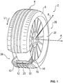
- FIG. 1 an advantageous embodiment of a vehicle tire 2 is shown in a schematic and partially transparent representation.
- a section 24 of the vehicle tire 2 is shown transparently. This allows the structure of the Detect vehicle tire 2.
- the vehicle tire 2 is fastened to a rim 26 by way of example. Together, the vehicle tire 2 and the rim 26 can form a wheel 28.
- the vehicle tire 2 is also referred to as tire 2.
- the vehicle tire 2 can roll in the circumferential direction U.
- the vehicle tire 2 can be mounted rotatably on a vehicle axle by means of the rim 26. If the vehicle tire 2 rolls on a ground, the tread 4 of the vehicle tire 2 comes into contact with the ground.
- the tread 4 can be formed by a belt section 30 of the vehicle tire 2.
- the belt section 30 is preferably an annular section of the vehicle tire 2. At each end face of the belt section 30, the vehicle tire 2 merges into a side wall 6 or 8.
- the radially inner end 32 or 34 of the respective side wall 6 or 8 is releasably connected or connectable to the rim 26 in a form-fitting and / or force-fitting manner.
- a tire interior 36 can be formed between the vehicle tire 2 and the rim 26. This can be filled with a working gas, in particular with air, so that an air pressure is created in the tire interior 36.
- the vehicle tire 2 also has an inner side 10 of the tire.
- the tire inner side 10 is preferably formed on the radially inner side and opposite to the tread 4.
- the inside of the tire 10 can therefore be a circumferential or annular inside of the vehicle tire 2.
- the inner side 10 of the tire is preferably formed by the belt section 30 of the vehicle tire 2.
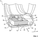
- a plurality of electronic modules 16 can be arranged indirectly on the inner side 10 of the vehicle tire 2. However, this is not necessary. It can thus be provided for the vehicle tire 2 that it has only a single electronic module 16, as shown in FIG Figure 1 is indicated. Here, too, it is provided that the electronics module 16 is arranged indirectly on the inner side 10 of the vehicle tire 2.
- the vehicle tire 2 also has foam 12.
- the foam 12 is preferably attached to the inside 10 of the tire by means of an adhesive layer 20 in a material manner. However, it can also be provided that the foam 12 is directly connected to the inner side 10 of the vehicle tire 2 in a material-like manner. Besides, it has has been found to be advantageous if the foam 12 is configured in an annular manner. Thus, the foam 12 can extend circumferentially in the circumferential direction U, so that the foam 12 is likewise connected circumferentially directly or indirectly to the tire inner side 10 of the vehicle tire 2.
- the foam 12 is, for example, a polyurethane foam 12.
- the foam 12 is particularly preferably designed to dampen sound waves. For this purpose, the foam 12 can be designed in the form of pores and / or have pores.
- the vehicle tire 2 also has a membrane 14.
- the membrane 14 is connected to the foam 12.
- the membrane 14 is designed to dampen sound waves.
- the membrane 14 can be designed as an aluminum membrane 14, for example.
- the membrane 14 can be designed in such a way that it can be excited to vibrate by a sound wave, so that the membrane 14 causes damping of the sound wave. This effect is preferably improved and / or reinforced in that the membrane 14 is connected to the foam 12. A periodic movement of the membrane 14 can therefore be dampened by the foam 12. This thus also contributes to the attenuation of sound waves that can develop in the tire interior 36.
- the membrane 14 is coupled to the electronics module 16. If several electronic modules 16 are provided, the membrane 14 can be coupled to each or to several electronic modules 16. However, this is not absolutely necessary. Therefore, for the sake of simplicity, the coupling between the membrane 14 and one of the electronic modules 16 is discussed below. This is intended to be representative of a possible configuration in which the membrane 14 can also be coupled to a plurality of electronic modules 16. The following explanations can therefore apply analogously to the couplings.
- the membrane 14 can be mechanically, electrically and / or functionally coupled to the electronics module 16.
- the electronics module 16 is mechanically fastened to the membrane 14.
- the membrane 12 itself is preferably attached to the foam 12 at least in sections and / or can be embedded in the foam 12 at least in sections.
- FIGS Figures 3 to 6 Possible configurations for a mechanical coupling between the membrane 14 and the electronics module 16 are shown in FIGS Figures 3 to 6 to be taken as an example.
- an exemplary embodiment of the vehicle tire 2 is shown in a schematic cross-sectional view.
- the foam 12 is attached to the inside of the tire 10 either directly or via an adhesive layer 20.
- the membrane 14 is arranged and / or fastened to the foam 12 on the radially inner side.
- an electronics module 16 is attached to the diaphragm 14 on the radially inner side.
- the membrane 14 can thus act as a mechanical connecting means between the foam 12 and the electronics module 16.
- the electronics module 16 can thus also have a direct mechanical connection to the foam 12 and / or to the inner side 10 of the vehicle tire. However, this is not in Figure 3 shown.
- an exemplary structure is shown in which the foam 12, the membrane 14 and the electronics module 16 are attached to one another in the radial direction R and / or are arranged one behind the other.
- FIG. 4 An exemplary embodiment of the vehicle tire 2 is shown here, in which the foam 12 is fastened directly or via an adhesive layer 20 to the inner side 10 of the tire.
- the membrane 14 is arranged laterally in the axial direction A on the foam 12, which provides a mechanical connection to the electronics module 16 that is also arranged axially on the outside of the membrane 14.
- the electronics module 16 can in this case have a direct connection to the inner side 10 of the vehicle tire 2.
- FIG Figure 5 Another advantageous embodiment of the vehicle tire 2 is shown in FIG Figure 5 shown. It is preferably provided that the foam 12 is connected to the tire inner side 10 of the vehicle tire 2 directly or via an adhesive layer 20. In addition, the membrane 14 is embedded in the foam 12. Furthermore, the Vehicle tires 2 have a further membrane 38. This further membrane 38 is also embedded in the foam 12 in such a way that it is arranged at a distance from the other membrane 14, and preferably parallel thereto. Both the electronics module 16 and a further electronics module 40 can be arranged between the two membranes 14, 38. Each of the two electronic modules 16, 40 can be coupled to two membranes 14, 38 in each case. In addition, it is preferably provided that the foam 12 is designed to be insulating, that is to say preferably electrically insulating.
- the two membranes 14, 38 can each be designed to be electrically conductive. You can therefore form electrical conductors. In this way, the membranes 14, 38 can act as electrical connections between the two electronic modules 16, 40. This is because the coupling of each electronic module 16, 40 to the two membranes 14, 38 can likewise be designed as an electrical coupling or as an electrical connection. Electrical signals can therefore be exchanged between the two electronic modules 16, 40 via the two membranes 14, 38.
- FIG. 6 a further advantageous embodiment of the vehicle tire 2 is shown.
- This embodiment of the vehicle tire 2 corresponds at least essentially to the advantageous embodiment of the vehicle tire 2, as it is in connection with Figure 3 has been explained.
- a further electronics module 40 is provided that is arranged on the radially inner side on the membrane 14 and / or fastened there.
- the electronics module 16 can be coupled to the membrane 14. This can be a mechanical coupling as well as an electrical coupling.
- the membrane 14 can thus contribute to the electronic module 16 being mechanically connected to the foam 12.
- the foam 12 can be designed to be electrically insulating. This offers the advantage that the electronics module 16 can use the membrane 14 as a functional component.
- the membrane 14 can for example be designed as an antenna. If the membrane 14 is electrically connected to the electronics module 16 as an antenna, the electronics module 16 can transmit and / or receive electromagnetic waves via the membrane 14.
- a tire-relevant measured value for example a pressure, a temperature and / or an acceleration
- a radio signal representing the measured value can be sent via the membrane 14 designed as an antenna. This can be received by a receiver unit which is arranged, for example, on a vehicle and / or stationary unit. The corresponding sensor data can then be evaluated here.
Landscapes
- Engineering & Computer Science (AREA)
- Mechanical Engineering (AREA)
- Tires In General (AREA)
Description
- Die Erfindung betrifft einen Fahrzeugreifen mit einer Lauffläche, Seitenwänden und einer Reifeninnenseite, wobei Schaumstoff an der Reifeninnenseite angeordnet ist, wobei eine zur Dämpfung von Schallwellen ausgebildete Membran mit dem Schaumstoff verbunden ist, wobei ein Elektronikmodul an der Reifeninnenseite angeordnet ist, und wobei die Membran mit dem Elektronikmodul gekoppelt ist.
- Fahrzeugreifen sind aus dem Stand der Technik bekannt. Ein Fahrzeugreifen wird auch als Kraftfahrzeugreifen, Reifen, Luftreifen oder Fahrzeugluftreifen bezeichnet.
- Ein Fahrzeugreifen eingangs genannter Art ist beispielsweise aus der
DE 10 2015 213 157 A1 bekannt. Dieser Fahrzeugreifen weist ein im Reifenhohlraum angeordnetes Reifenmodul mit einem Gehäuse und einem Elektronikmodul auf, wobei das Reifenmodul mit einem im Reifenhohlraum angeordneten Schallabsorber und einem Energieerzeuger in Verbindung steht. Der Schallabsorber ist mit seiner Unterseite an der Reifeninnenseite befestigt. Der Energieerzeuger ist eine Piezofolie, welche auf der Oberseite des Schallabsorbers angeklebt ist, wobei das Reifenmodul auf der Oberseite der Piezofolie mit einem Klebemittel montiert ist. - Aus der
DE 10 2007 028 932 A1 ist ein Fahrzeugreifen bekannt, bei dem ein Schaumstoffring an der Reifeninnenseite angebracht ist. Der Schaumstoffring dient zur Schallabsorption. - Bei einem auf einer Fahrbahn abrollenden Fahrzeugreifen entstehen oftmals Schallwellen, die als Geräusche wahrgenommen werden. Die Schallwellen können durch Vibration der Luft im von dem Reifen und einer Felge eingeschlossenen Radinnenraum verursacht sein. Bei einem Fahrzeugreifen für einen Personenkraftwagen entstehen so oftmals Schallwellen mit einer Frequenz zwischen 170 Hertz und 270 Hertz. Dieser Frequenzbereich ist oftmals auf die Geometrie des Fahrzeugreifens zurückzuführen. Insbesondere kann hierbei der Umfang des Fahrzeugreifens Einfluss haben. Denn die Schallwellen können in dem geschlossenen Radinnenraum verlaufende Raummoden bilden, die zu der von dem Fahrzeugreifen bestimmten Resonanzfrequenz korrespondieren. Eine übliche Resonanzfrequenz liegt also innerhalb des zuvor genannten Frequenzbereiches oder bei einem Vielfachen davon. Die durch die Schallwellen verursachten Geräusche können im Fahrgastraum eines Fahrzeugs wahrgenommen werden.
- Aus dem Stand der Technik sind Fahrzeugreifen mit einem Sensor bekannt. So kann ein Fahrzeugreifen beispielsweise einen Drucksensor aufweisen, der an der Reifeninnenseite stoffflüssig befestigt ist.
- Der Erfindung liegt die Aufgabe zugrunde, einen Fahrzeugreifen bereitzustellen, der sowohl eine Elektronikfunktionalität als auch ein möglichst niedriges Geräuschniveau beim Abrollen auf einer Fahrbahn gewährleistet.
- Gelöst wird die Aufgabe durch einen Fahrzeugreifen mit den Merkmalen des kennzeichnenden Teiles des Anspruchs 1. Vorgesehen ist also ein Fahrzeugreifen, bei welchem zumindest eine Außenseite des Elektronikmoduls direkt an der Reifeninnenseite befestigt ist.
- Bei dem Schaumstoff handelt es sich vorzugsweise um einen künstlich hergestellten Schaumstoff. Der Schaumstoff kann Kunststoff aufweisen oder daraus bestehen. Außerdem handelt es sich vorzugsweise um einen Kunststoff aus festem Material. Bei dem Kunststoff handelt es sich also vorzugsweise nicht um Schaum aus Flüssigkeit. Der Schaumstoff weist vorzugsweise eine zellige Struktur und/oder Poren auf. Bei dem Schaumstoff kann es sich also um ein poröses Material handeln. Es kann sich bei dem Schaumstoff um einen offenzelligen Schaumstoff oder um einen gemischtzelligen Schaumstoff oder um einen geschlossenzelligen Schaumstoff handeln. Der Schaumstoff kann beispielsweise ein thermoplastischer Schaumstoff, ein elastomerer Schaumstoff oder ein duoplastischer Schaumstoff sein.
- Bei dem Schaumstoff kann es sich um ContiSilent®-Schaum, Polyurethan-Schaum und/oder Polyester-Schaum handeln. Der Schaumstoff kann eine Dichte von 20 kg/m3 bis 85 kg/m3 oder 100 kg/m3, eine Härte von 3,5 kilo-pascal bis 10 kilo-pascal und/oder eine Stauchhärte von 1,5 kilo-pascal aufweisen. Weitere mögliche poröse Materialien als Schaumstoff können beispielsweise eine Mischung aus Polyurethan und/oder Polyester und/oder Polyether, oder Polyurethanschäume auf einer Polyetherbasis oder einer Polyesterbasis aufweise, und/oder sie weisen eine beliebige, schallabsorbierende Materialienmischung, beispielsweise Glas- oder Steinwolle, Schlingenware oder Hochflor oder Vliesmaterialien oder Kork auf. Weitere mögliche poröse Materialien als Schaumstoff sind beispielsweise ein Melaminharzschaum oder ein Bauschaum.
- Der Schaumstoff kann zur akustischen Dämpfung ausgebildet sein. Beispielsweise kann der Schaumstoff derart ausgebildet sein, dass sich wiederholende Frequenzen der in dem Fahrzeugreifen entstehenden Schallwellen von dem Schaumstoff gedämpft, insbesondere effektiv gedämpft, und/oder unterdrückt werden können. So kann der Schaumstoff beispielsweise dazu ausgebildet sein, Schallwellen mit einer vorbestimmten Frequenz besonders effektiv zu dämpfen und/oder sogar zu isolieren.
- Der Schaumstoff kann segmentiert in Schaumstoffabschnitte unterteilt sein. Jeder Schaumstoffabschnitt kann ein akustisches Dämpfungselement bilden. Ist der Schaumstoff als durchgängiger Schaumstoff ausgebildet, so kann sich der Schaumstoff beispielsweise in Umfangsrichtung des Fahrzeugreifens, vorzugsweise umlaufend und/oder ringförmig in Umfangsrichtung des Fahrzeugreifens, erstrecken. Sofern der Schaumstoff als durchgängiger Schaumstoff ausgebildet ist, können die zuvor genannten Dämpfungselemente als integrale Dämpfungselemente des Schaumstoffs ausgebildet sein.
- Der Schaumstoff ist vorzugsweise an einem Abschnitt an der Reifeninnenseite angeordnet. So ist es nicht zwingend notwendig, dass sich der Schaumstoff ringförmig über die gesamte Umlaufrichtung der Reifeninnenseite erstreckt. Jedoch ist es von Vorteil und auch bevorzugt, dass der Schaumstoff eine ringförmige Form hat, und umlaufend an der Reifeninnenseite angeordnet ist. Der Schaumstoff kann an der Reifeninnenseite stoffflüssig befestigt sein. Der Schaumstoff bzw. die zugehörigen Schaumstoffabschnitte können mittels eines Haftmittels an der Reifeninnenseite befestigt sein. Bei dem Haftmittel kann es sich um ein Dichtmittel und/oder ein Klebemittel handeln.
- Bei dem Dichtmittel handelt es sich beispielsweise um ein Polyurethan-Gel oder um eine butylkautschukbasiertes Dichtmittel. Bevorzugt handelt es sich um ein butylkautschukbasiertes Dichtmittel in Kombination mit einem Klebemittel. Bei dem Klebemittel kann es sich um ein Klebeband und/oder einen silikonbasierten Kleber und/oder einen Zwei-Komponenten-Kleber und/oder einen Baukleber und/oder einen Polyurethan-Kleber und/oder einen kautschukbasierten Kleber und/oder einen Reifenreparaturkleber und/oder einen Sekundenkleber und/oder einen Kleber basierend auf Cyanacrylat und/oder basierend auf einem wasserbasierten Acryl-System mit einer Polyethylenterephthalat-Struktur und/oder basierend auf Acryl-Nitril-Butadien-Kautschuk in Verbindung mit einem in Aceton gelösten Formaldehyd-Harz und/oder basierend auf einem Silan-Polyether und/oder basierend auf einem mit Butyl-Kautschuk vernetzten Polybuten und/oder basierend auf einem Alkoxy-Silikon handeln.
- Die Membran des Fahrzeugreifens ist zur Dämpfung von Schallwellen ausgebildet. So kann die Membran beispielsweise zur Dämpfung von Schallwellen mit einer Frequenz zwischen 170 Hz und 260 Hz ausgebildet sein. Vorzugsweise ist die Membran ausgebildet, von einer Schallwelle zu Schwingungen angeregt zu werden, so dass die Membran eine Dämpfung der Schallwelle verursacht. Die Membran kann beispielsweise ausgebildet sein als: eine Kunststofffolie, eine Metallfolie, insbesondere eine Aluminiumfolie, eine gewebeverstärkte Membran, eine Naturmaterialien aufweisende Membran, eine Kohlenstofffasern aufweisende Membran, eine Aramid oder Aramidfasern aufweisende Membran, eine Gummimembran, oder eine Moosgummimembran. Die Membran kann auch aus einer Kombination von mindestens zwei der zuvor genannten Ausgestaltungen ausgebildet sein.
- Vorzugsweise ist die Membran nach Art eines Gewebes, eines Gitters und/oder eines Netzes ausgebildet. Dabei können die fadenförmigen Elemente aus Kunststoff oder Metall gebildet sein. So kann die Membran beispielsweise von einem Kunststoff-Gitter oder einem Metallgitter gebildet sein. Die Membran kann aber auch eine andere Form aufweise. So kann die Membran beispielsweise nach Art einer Antenne, insbesondere nach Art einer ringförmigen oder baumförmigen Antenne, ausgebildet sein.
- Die Membran ist mit dem Schaumstoff verbunden. Sollte die Membran zu Schwingungen angeregt werden, insbesondere durch die in dem Fahrzeugreifen entstehenden Schallwellen, so kann die Verbindung zwischen der Membran und dem Schaumstoff dazu beitragen, dass die Schallwellen von dem Schaumstoff und der Membran gemeinsam gedämpft werden.
- An der Reifeninnenseite des Fahrzeugreifens ist ein Elektronikmodul direkt angeordnet. Bei einer direkten Anordnung kann das Elektronikmodul beispielsweise direkt an der Reifeninnenseite stoffschlüssig befestigt sein.
- Ein Elektronikmodul weist vorzugsweise elektronische Bauteile auf. So kann das Elektronikmodul beispielsweise einen Drucksensor zur Erfassung des Luftdrucks aufweisen. In der Praxis wurde festgestellt, dass für das Elektronikmodul weitere Funktionen vorgesehen sein können, wie beispielsweise eine Datenverarbeitungseinheit und eine Funkeinheit. Für die Datenverarbeitungseinheit kann eine Kühlrippe vorgesehen sein. Für die Funkeinheit kann eine Antenne vorgesehen sein. Bei einem steigenden Funktionsumfang des Elektronikmoduls steigt auch das Gewicht des Elektronikmoduls. Ist ein derartiges Elektronikmodul nun an der Reifeninnenseite des Fahrzeugreifens zu befestigen, verursacht dies eine hohe Gewichtskonzentration an einer Stelle der Reifeninnenseite des Fahrzeugreifens. Wird der Fahrzeugreifen nun bei Verwendung einer hohen Rotationsgeschwindigkeit ausgesetzt, führt die hohe Gewichtskonzentration des Elektronikmoduls zu einem spürbaren und/oder messbaren Unwuchtverhalten bzw. Geräuschverhalten des Fahrzeugreifens, was jedoch zu verhindern ist.
- Für den Fahrzeugreifen ist es deshalb vorgesehen, dass die Membran mit dem Elektronikmodul gekoppelt ist. Durch die Kopplung der Membran mit dem Elektronikmodul kann eine funktionelle, elektrische und/oder mechanische Kopplung gemeint sein. Dies bietet den Vorteil, dass die Membran einen Teil des Elektronikmoduls ersetzt und/oder eine Funktion für das Elektronikmodul bereitstellt. So kann die Membran beispielsweise als Antenne für das Elektronikmodul wirken, indem die Membran mit dem Elektronikmodul gekoppelt ist. Das Elektronikmodul als solches benötigt in diesem Beispiel deshalb keine eigene Antenne. Dadurch kann das Gewicht des Elektronikmoduls reduziert werden, was ein besseres Unwuchtverhalten und ein besseres Geräuschverhalten des Fahrzeugreifens gewährleisten kann. Ein anderes Beispiel für die Kopplung der Membran mit dem Elektronikmodul kann sich beispielsweise auf eine mechanische Kopplung zwischen der Membran und dem Elektronikmodul beziehen. So kann das Elektronikmodul von der Membran gehalten und/oder gestützt sein. Dies ist insbesondere bei Fahrzeugreifen von Vorteil, die hohen Beschleunigungen ausgesetzt sein können. Denn aufgrund der bevorzugten mechanischen Kopplung des Elektronikmoduls an die Membran ist das Elektronikmodul nicht mehr notwendigerweise nur direkt oder indirekt an der Reifeninnenseite mechanisch befestigt. Vielmehr kann in diesem Fall auch eine zusätzliche mechanische Befestigung des Elektronikmoduls aufgrund der Kopplung zu der Membran und aufgrund der Verbindung der Membran zum Schaumstoff an die Reifeninnenseite gewährleistet werden. Wird das Elektronikmodul nun in Radialrichtung und/oder in Umfangsrichtung des Fahrzeugreifens stark beschleunigt, kann die Membran dazu beitragen, dass sich das Elektronikmodul nicht von der Reifeninnenseite des Fahrzeugreifens löst. Insbesondere wenn die Membran aus elektrisch leitfähigen Material ist oder dieses aufweist, kann auch eine elektrische Kopplung zwischen der Membran und dem Elektronikmodul vorgesehen sein. So kann die Membran beispielsweise als elektrische Verbindungsleitung für das Elektronikmodul zu einem weiteren Bauteil wirken. Dies kann beispielsweise derart ausgebildet sein, dass die Membran eine elektrische Verbindung zwischen dem Elektronikmodul und einem weiteren Elektronikmodul des Fahrzeugreifens oder eine elektrische Verbindung zwischen dem Elektronikmodul und einer Batterie bildet.
- Die Membran kann also eine Doppelfunktion aufweisen. Die Membran ist zur Dämpfung von Schallwellen ausgebildet. Außerdem ist die Membran zur Ankopplung an das Elektronikmodul ausgebildet, um durch diese Kopplung eine funktionale, mechanische und/oder elektrische Verbindung zu dem Elektronikmodul zu gewährleisten. Unter der elektrischen Verbindung kann insbesondere auch eine Funkverbindung verstanden werden.
- Eine vorteilhafte Ausgestaltung des Fahrzeugreifens zeichnet sich dadurch aus, dass die Membran zumindest abschnittsweise an dem Schaumstoff befestigt ist. So kann die Membran beispielsweise an einer Oberseite des Schaumstoffs angeordnet und/oder dort mit dem Schaumstoff befestigt sein. Die Membran kann stoffschlüssig mit dem Schaumstoff verbunden sein. Durch die mechanische Befestigung der Membran an dem Schaumstoff kann der Schaumstoff zur Absorption von Schwingungen der Membran dienen und/oder wirken. Dies gewährleistet eine besonders vorteilhafte Dämpfung von Schallwellen, die sich in dem Fahrzeugreifen ausbreiten können.
- Eine weitere vorteilhafte Ausgestaltung des Fahrzeugreifens zeichnet sich dadurch aus, dass die Membran zumindest abschnittsweise in den Schaumstoff eingebettet ist. So kann beispielsweise ein Endabschnitt der Membran in den Schaumstoff eingebettet sein. Ein weiterer Abschnitt kann von dem Schaumstoff abstehen und/oder wegragen. Es ist jedoch auch möglich, dass die Membran vollständig oder zumindest großteilig in den Schaumstoff eingebettet ist. Durch die Einbettung kann eine stoffflüssige Verbindung zwischen der Membran und dem Schaumstoff gebildet sein. Dies gewährleistet eine mechanische Befestigung in der Membran an dem Schaumstoff. Durch diese mechanische Befestigung kann der Schaumstoff ebenfalls zur Absorption von Schwingungen der Membran dienen und/oder wirken. Dies gewährleistet ebenfalls eine besonders vorteilhafte Dämpfung von Schallwellen, die sich in dem Fahrzeugreifen ausbreiten können.
- Eine weitere vorteilhafte Ausgestaltung des Fahrzeugreifens zeichnet sich dadurch aus, dass zumindest eine Außenseite des Elektronikmoduls an der Reifeninnenseite befestigt ist. Diese Befestigung kann mittels eines Haftmittels, beispielsweise mittels einer Klebeschicht, erfolgen. Das Elektronikmodul kann deshalb besonders bevorzugt stoffschlüssig an der Reifeninnenseite befestigt sein.
- Eine weitere vorteilhafte Ausgestaltung des Fahrzeugreifens zeichnet sich dadurch aus, dass der Schaumstoff zwischen der Reifeninnenseite und dem Elektronikmodul derart angeordnet ist, sodass das Elektronikmodul auf dem Schaumstoff angeordnet und/oder zumindest teilweise in den Schaumstoff eingebettet ist. Der Schaumstoff kann also zur Anordnung des Elektronikmoduls an der Reifeninnenseite dienen und/oder dazu ausgebildet sein. Außerdem ist es möglich, dass das Elektronikmodul mittels des Schaumstoffs an der Reifeninnenseite befestigt ist. Wird der Schaumstoff zur Befestigung des Elektronikmoduls verwendet, kann es vorgesehen sein, dass das Elektronikmodul indirekt an der Reifeninnenseite befestigt ist. Dies ist insbesondere dann der Fall, wenn zwischen der Reifeninnenseite und dem Elektronikmodul ein Teil des Schaumstoffs angeordnet ist. Dies bietet jedoch auch Vorteile. Denn wenn die Lauffläche in Radialrichtung beansprucht wird, kann dies zu einer Beschleunigung des Elektronikmoduls in Radialrichtung führen. Ist der Schaumstoff zwischen der Reifeninnenseite und dem Elektronikmodul angeordnet, kann die auf das Elektronikmodul wirkende Kraft gedämpft sein. Der Schaumstoff kann also auch zum Schutz des Elektronikmoduls dienen.
- Eine vorteilhafte Ausgestaltung des Fahrzeugreifens zeichnet sich dadurch aus, dass das Elektronikmodul direkt mit der Membran gekoppelt ist. So kann die Membran beispielsweise eine direkte mechanische Verbindung zu dem Elektronikmodul aufweisen. Dies ist insbesondere dann von Vorteil, wenn die Membran auch zum Befestigen, Stützen und/oder Halten des Elektronikmoduls dient und/oder dazu ausgebildet ist. Ist beispielsweise ein Abschnitt der Membran in den Schaumstoff eingebettet und ist ein anderer Abschnitt der Membran direkt, insbesondere durch eine mechanische, direkte Verbindung, mit dem Elektronikmodul verbunden bzw. gekoppelt, so kann die Membran ebenfalls zumindest dazu beitragen, dass das Elektronikmodul an der vorgesehenen Stelle an der Reifeninnenseite des Fahrzeugreifens angeordnet ist und bleibt. Dies gilt insbesondere für den Fall, wenn der Schaumstoff als solcher ebenfalls zur Befestigung des Elektronikmoduls dient. Denn in diesem Fall können die Membran und der Schaumstoff gemeinsam zur Befestigung, Halten und/oder Stützen des Elektronikmoduls dienen und/oder dazu ausgebildet sein. Die direkte Kopplung der Membran an das Elektronikmodul kann jedoch auch andere Vorteile bieten. Dies gilt insbesondere dann, wenn die Membran eine Funktion für das Elektronikmodul bereitstellt. Dient die Membran beispielsweise als Kühlkörper für ein Elektronikbauteil des Elektronikmoduls, so gewährleistet die direkte Kopplung bzw. die direkte Verbindung zwischen der Membran und dem Elektronikmodul bzw. dem zugehörigen Bauteil, dass thermische Energie von dem Elektronikmodul an die Membran übertragen werden kann, die sodann die thermische Energie an die Umgebung, insbesondere den Schaumstoff und/oder den restlichen Fahrzeugreifen, übertragen kann.
- Eine weitere vorteilhafte Ausgestaltung des Fahrzeugreifens zeichnet sich dadurch aus, dass das Elektronikmodul mittels der Membran an dem Schaumstoff befestigt ist. Die Membran kann also auch als mechanisches Verbindungsmittel wirken. In diesem Zusammenhang wird auf die vorangegangen Erläuterungen in analoger Weise Bezug genommen. Es kann jedoch auch vorgesehen sein, dass das Elektronikmodul nur mittels der Membran verbunden ist, und die Membran mit dem Schaum verbunden ist. In diesem Fall kann also das Elektronikmodul mittels der Membran an dem Schaumstoff hängend befestigt sein. Dabei kann es vorgesehen sein, dass das Elektronikmodul keinen direkten Kontakt zu dem Schaumstoff und/oder keinen direkten Kontakt zu der Reifeninnenseite des Fahrzeugreifens aufweist. Es ist jedoch vorgesehen, dass das Elektronikmodul beispielsweise durch einen trennenden Luftspalt zu der Reifeninnenseite angeordnet ist. Der Luftspalt kann beispielsweise in Radialrichtung nur wenige Millimeter, beispielsweise weniger als fünf Millimeter, betragen. Diese Anordnung wird deshalb ebenfalls als eine indirekte Anordnung des Elektronikmoduls an der Reifeninnenseite aufgefasst, da das Elektronikmodul über die Membran und dem Schaumstoff eine Verbindung zu der Reifeninnenseite aufweist und das Elektronikmodul besonders dicht an der Reifeninnenseite, nämlich nur beabstandet durch einen sehr schmalen Luftspalt, zu dieser angeordnet ist. Die Membran kann dabei ausgebildet sein, eine schwingungsdämpfende und/oder schwingungsisolierende Aufhängung für das Elektronikmodul zu bilden. Dies bietet den Vorteil, dass das Elektronikmodul besonders geschützt vor mechanischen Stößen sein kann. Außerdem kann durch diese Befestigungsart eine besonders einfache Applikation des Elektronikmoduls erfolgen. Denn das Elektronikmodul bedarf in diesem Fall keiner direkten stoffflüssigen Verbindung zu der Reifeninnenseite. Zusammenfassend kann also festgehalten werden, dass die Befestigung des Elektronikmoduls mittels der Membran an den Schaum eine vollständige oder eine schützende Befestigung sein kann. Die Befestigung kann also zum Aufhängen, Abstützen und/oder Halten dienen.
- Eine vorteilhafte Ausgestaltung des Fahrzeugreifens zeichnet sich dadurch aus, dass das Elektronikmodul indirekt mittels mindestens einem Verbindungsmittel mit der Membran gekoppelt ist. Dient die Membran beispielsweise als funktionales Bauteil für das Elektronikmodul und/oder dient die Membran zur Bereitstellung einer Funktion für das Elektronikmodul, ist es nicht immer notwendig, dass eine direkte und/oder mechanische Verbindung zwischen der Membran und dem Elektronikmodul besteht. Deshalb kann auch das Verbindungsmittel eingesetzt werden, um die Kopplung zwischen dem Elektronikmodul und der Membran zu schaffen. Das Verbindungsmittel kann beispielsweise ein elektrisches Verbindungskabel sein. In diesem Fall kann eine elektrische und/oder mechanische Verbindung zwischen dem Elektronikmodul und der Membran über das Verbindungsmittel gewährleistet und/oder gebildet sein. Darüber hinaus ist es möglich, dass zwischen dem Elektronikmodul und der Membran keine mechanische und/oder durch mechanische Elemente geschaffene Verbindung vorhanden ist. So kann dem Elektronikmodul beispielsweise eine Funkeinheit zugeordnet sein. Diese Funkeinheit kann als ein Verbindungsmittel dienen. Denn zwischen der Funkeinheit und der Membran kann beispielsweise eine Funkverbindung hergestellt sein, die eine Kopplung zwischen dem Elektronikmodul und der Membran gewährleistet. Die Funkverbindung kann als eine elektrische Verbindung bzw. als eine elektrische Funkverbindung verstanden sein. Durch die Funkverbindung können elektrische Signale von dem Elektronikmodul an die Membran, oder umgekehrt, übertragen werden.
- Eine vorteilhafte Ausgestaltung des Fahrzeugreifens zeichnet sich dadurch aus, dass die Membran zum Empfang und/oder zum Aussenden einer elektromagnetischen Welle ausgebildet ist. Die Membran kann als Antenne ausgebildet sein. Dabei kann die Membran direkt mit dem Elektronikmodul gekoppelt sein, sodass die Membran eine Antenne für das Elektronikmodul bildet. Somit kann über die Membran eine elektromagnetische Welle ausgesendet werden, die durch ein elektrisches Signal des Elektronikmoduls verursacht wird. Es ist aber auch möglich, dass die Membran zum Empfang einer elektromagnetischen Welle ausgebildet ist, sodass von der Membran ein elektrisches Signal an das Elektronikmodul gesendet und/oder übertragen wird. Sind die Membran und das Elektronikmodul über Funk miteinander verbunden, so kann die Membran dazu ausgebildet sein, ein Funksignal an das Elektronikmodul zu senden und/oder in umgekehrter Weise ein Funksignal von dem Elektronikmodul zu empfangen. Bei dem Funksignal handelt es sich vorzugsweise um ein Signal basierend auf einer elektromagnetischen Welle.
- Eine weitere vorteilhafte Ausgestaltung des Fahrzeugreifens zeichnet sich dadurch aus, das die Membran elektrisch leitfähig ausgebildet ist. Die Membran kann beispielsweise elektrische leitfähiges Material aufweisen und/oder daraus ausgebildet sein. So kann die Membran aus Metall gebildet sein. Beispielsweise kann die Membran als Aluminium-Membran ausgebildet sein. Durch die elektrisch leitfähige Eigenschaft der Membran ist es möglich, dass die Membran elektrischen Strom leiten kann. Dies ist insbesondere dann von Vorteil, wenn die Membran direkt mit dem Elektronikmodul verbunden ist, denn in diesem Fall kann die Membran als elektrisches Verbindungsmittel zu einem weiteren Bauteil dienen.
- Eine weitere vorteilhafte Ausgestaltung des Fahrzeugreifens zeichnet sich dadurch aus, dass die Membran zum Übertragen von elektrischer Energie, insbesondere zum Leiten eines elektrischen Stroms, ausgebildet ist. So kann die Membran beispielsweise mindestens zwei elektrische Leiter aufweisen und/oder ausbilden. Die Membran kann beispielsweise zwei Leiterbahnen oder noch weitere Leiterbahnen aufweisen, wobei jede Leiterbahn zum Leiten von elektrischem Strom ausgebildet ist. Die Leiterbahnen können elektrisch voneinander isoliert sein. Hierzu kann die Membran entsprechend ausgebildet sein. Sofern noch weitere Leiterbahnen vorgesehen sind, können auch diese von der Membran elektrisch zu den übrigen Leiterbahnen elektrisch isoliert ausgebildet sein. Über eine oder mehrere der Leiterbahnen kann elektrischer Strom fließen. Deshalb ist es möglich, dass ein Elektronikmodul beispielsweise über zwei Leiterbahnen, die von der Membran gebildet sind, mit einem anderen Bauteil, insbesondere einem weiteren Elektronikmodul, elektrisch verbunden ist. Außerdem kann die Membran ausgebildet sein, um ein elektrisches Leiterbahnnetzwerk auszubilden.
- Eine weitere vorteilhafte Ausgestaltung des Fahrzeugreifens zeichnet sich dadurch aus, dass die Membran als elektrische Energiequelle ausgebildet ist. So kann der Membran beispielsweise eine Batterie oder ein Akku zugeordnet sein. Dieser kann an der übrigen Membran befestigt sein. Es ist jedoch auch möglich, dass die Membran zum kontaktlosen Empfang von elektrischer Energie ausgebildet ist, so beispielsweise zum Empfangen von elektrischer Energie per Induktion. In diesem Fall kann die Membran ebenfalls als Energiequelle für ein weiteres elektrisches Bauteil, insbesondere für das Elektronikmodul dienen. Ist die Membran beispielsweise mit dem Elektronikmodul gekoppelt und außerdem zum Empfangen von elektrischer Energie ausgebildet, so kann das Elektronikmodul mit elektrischer Leistung über die Membran versorgt werden.
- Eine vorteilhafte Ausgestaltung des Fahrzeugreifens zeichnet sich dadurch aus, dass mindestens ein weiteres, derartiges Elektronikmodul direkt oder indirekt an der Reifeninnenseite angeordnet ist. Somit kann der Fahrzeugreifen mehrere Elektronikmodule aufweisen, die jeweils direkt oder indirekt an der Reifeninnenseite angeordnet sind. Die mehreren Elektronikmodule sind nicht notwendigerweise gleich ausgestaltet, obwohl dies möglich ist. Vielmehr können die Elektronikmodule untereinander unterschiedlich ausgebildet sein. Für das mindestens eine weitere Elektronikmodul wird jedoch zumindest in analoger Weise auf die vorangegangen Erläuterungen, bevorzugten Merkmale und/oder Effekte verwiesen, wie sie im Zusammenhang mit dem zuvor erläuterten Elektronikmodul erläutert worden sind, Bezug genommen.
- Eine weitere vorteilhafte Ausgestaltung des Fahrzeugreifens zeichnet sich dadurch aus, dass die Elektronikmodule mit der Membran gekoppelt sind. Weist der Fahrzeugreifen beispielsweise zwei oder noch weitere Elektronikmodule auf, so kann jedes der Elektronikmodule mit der gleichen Membran gekoppelt sein. Bezüglich der Kopplung zwischen der Membran und jedem der Elektronikmodul wird auf die vorangegangenen, bevorzugten Erläuterungen, bevorzugten Merkmale, Effekte und/oder Vorteile verwiesen, wie sie bereits im Zusammenhang mit der Kopplung der Membran und dem Elektronikmodul erläutert worden sind. Indem mehrere Elektronikmodule mit der gleichen Membran gekoppelt sind, kann die Membran eine funktionale, elektrische und/oder mechanische Kopplung zwischen den Elektronikmodulen bilden. So können die Elektronikmodule beispielsweise über die Membran elektrisch miteinander gekoppelt sein, um elektrische Energie und/oder um elektrische Signale auszutauschen. Wird beispielsweise ein Elektronikmodul durch eine Funkeinheit gebildet und ein weiteres Elektronikmodul durch eine Sensoreinheit, beispielsweise mit einem Drucksensor, einem Temperatursensor oder einem Beschleunigungssensor, so kann die Membran eine elektrische Signalverbindung zwischen dem Sensormodul und der Funkeinheit bilden, sodass ein von der Sensoreinheit erfasster Sensorwert durch ein elektrisches Signal repräsentiert wird, das über die Membran von der Sensoreinheit an die Funkeinheit übertragen werden kann, die wiederum basierend auf dem übertragenden, elektrischen Signal ein Funksignal erzeugt, dass an einen Funkempfänger übertragen werden kann, und zwar per Funk. Mit der Membran und den mehreren Elektronikmodulen kann deshalb eine funktionale Aufteilung von Funktionen geschaffen werden. Dies wiederum gewährleistet die in Umfangsrichtung verteilte Anordnung von Elektronikmodulen, was eine besonders geringe Unwucht ermöglicht.
- Eine vorteilhafte Ausgestaltung des Fahrzeugreifens zeichnet sich dadurch aus, dass die Membran eine elektrische Verbindung zwischen den Elektronikmodulen bildet. Hierbei handelt es sich vorzugsweise um die Elektronikmodule des Fahrzeugreifens. Darüber hinaus wird auf die vorangegangenen Erläuterungen zumindest in analoger Weise verwiesen, wobei die elektrische Verbindung die Kopplung zwischen der Membran und den Elektronikmodulen bilden kann. Die elektrische Verbindung kann auch dazu dienen, um elektrische Leistung von einem Elektronikmodul zu einem anderen Elektronikmodul zu übertragen. So kann beispielsweise ein Elektronikmodul eine Batterie aufweisen und/oder davon gebildet sein. Von diesem Elektronikmodul kann elektrische Leistung über die Membran an ein weiteres Elektronikmodul übertragen werden, wenn dies ebenfalls mit der Membran elektrisch verbunden ist.
- Eine weitere vorteilhafte Ausgestaltung des Fahrzeugreifens zeichnet sich dadurch aus, dass mindestens eine weitere derartige Membran mit dem Schaumstoff verbunden ist, wobei jedes Elektronikmodul mit mindestens einer der Membranen gekoppelt ist. So kann es beispielsweise vorgesehen sein, dass jedes Elektronikmodul mit genau einer Membran gekoppelt ist. In diesem Fall kann beispielsweise pro Membran genau ein Elektronikmodul vorgesehen sein. Dies ist jedoch nicht notwendig. Vielmehr kann es vorgesehen sein, dass mehrere Elektronikmodule mit jeweils der gleichen Membran verbunden sind. Die Membrane können also die Verbindungen zwischen den Elektronikmodulen gewährleisten. Die Verbindungen können dabei mechanische, elektrische und/oder funktionale Verbindungen sein. Somit ist es möglich, dass jedes Elektronikmodul mit mindestens zwei Membranen oder sogar mit jeder Membran gekoppelt sein kann. Als besonders vorteilhaft hat es sich herausgestellt, wenn die Membranen parallel zueinander ausgerichtet und/oder angeordnet sind. Denn in diesem Fall können die Elektronikmodule in dem Zwischenraum angeordnet sein, der sich zwischen der parallelen Anordnung der Membranen bildet. Dies bietet den Vorteil, dass jedes Elektronikmodul eine Kopplung zu jeder der Membranen aufweisen kann.
- Als besonders vorteilhaft hat es sich herausgestellt, wenn eine oder jede Membran lateral, horizontal oder radial ausgerichtet ist. So kann jede Membran beispielsweise in Radialrichtung ausgerichtet sein. Es ist jedoch auch möglich, dass eine oder jede Membran in Umfangsrichtung des Fahrzeugreifens ausgerichtet und/oder ausgebildet ist. Ebenfalls ist es möglich, dass eine oder jede Membran in Axialrichtung ausgerichtet ist. Zwei in Radialrichtung oder Axialrichtung voneinander beabstandete Membranen können zwei Leiterbahnen zur Übertragung von elektrischer Energie bilden. Dabei können die Membranen von dem Schaumstoff elektrisch isoliert sein. Der Schaumstoff kann also elektrisch isolierend oder als Isolator ausgebildet sein. Wird elektrische Energie mittels einer oder der Membranen übertragen, kann der Schaumstoff als Isolator dienen. Wird von einer Membran eine Leiterbahn gebildet, so kann jede Membran einen Pol, insbesondere einen Pluspol oder einen Minuspol, bilden. Der mindestens eine Pol kann ein Anschlusspol für ein Elektronikmodul bilden. Somit kann ein Elektronikmodul mit mindestens einem der zuvor genannten Pole gekoppelt und/oder verbunden sein.
- Weitere Merkmale, Vorteile und Anwendungsmöglichkeiten der vorliegenden Erfindung ergeben sich aus der nachfolgenden Beschreibung der Ausführungsbeispiele und den Figuren. Dabei bilden alle beschriebenen und/oder bildlich dargestellten Merkmale für sich und in beliebiger Kombination den Gegenstand der Erfindung auch unabhängig von ihrer Zusammensetzung in den einzelnen Ansprüchen oder deren Rückbezügen. In den Figuren stehen weiterhin gleiche Bezugszeichen für gleiche oder ähnliche Objekte.
- Figur 1
- zeigt eine vorteilhafte Ausgestaltung eines Fahrzeugreifens in einer schematischen und teiltransparenten Ansicht.
- Figur 2
- zeigt einen Ausschnitt einer weiteren vorteilhaften Ausgestaltung eines Fahrzeugreifens in einer schematischen Schnittdarstellung.
- Figuren 3 bis 6
- zeigen jeweils eine vorteilhafte Ausgestaltung des Fahrzeugreifens in einer schematischen Querschnittsansicht.
- In der
Figur 1 ist eine vorteilhafte Ausgestaltung eines Fahrzeugreifens 2 in einer schematischen und teiltransparenten Darstellung gezeigt. Dabei ist ein Ausschnitt 24 des Fahrzeugreifens 2 transparent dargestellt. Dadurch lässt sich der Aufbau des Fahrzeugreifens 2 erkennen. Der Fahrzeugreifen 2 ist beispielhaft an einer Felge 26 befestigt. Zusammen können der Fahrzeugreifen 2 und die Felge 26 ein Rad 28 bilden. Der Fahrzeugreifen 2 wird auch als Reifen 2 bezeichnet. - In der praktischen Anwendung kann der Fahrzeugreifen 2 in Umfangsrichtung U abrollen. Dazu kann der Fahrzeugreifen 2 mittels der Felge 26 an einer Fahrzeugachse drehbar gelagert befestigt sein. Rollt der Fahrzeugreifen 2 auf einem Untergrund ab, kommt die Lauffläche 4 des Fahrzeugreifens 2 mit dem Untergrund in Kontakt. Die Lauffläche 4 kann von einem Gürtelabschnitt 30 des Fahrzeugreifens 2 gebildet sein. Bei dem Gürtelabschnitt 30 handelt es sich vorzugsweise um einen ringförmigen Abschnitt des Fahrzeugreifens 2. Zu jeder Stirnseite des Gürtelabschnitts 30 geht der Fahrzeugreifen 2 in eine Seitenwand 6 bzw. 8 über. Das radialinnenseitige Ende 32 bzw. 34 der jeweiligen Seitenwand 6 bzw. 8 ist formschlüssig und/oder kraftschlüssig mit der Felge 26 lösbar verbunden bzw. verbindbar. Zwischen dem Fahrzeugreifen 2 und der Felge 26 kann ein Reifeninnenraum 36 gebildet sein. Dieser kann mit einem Arbeitsgas, insbesondere mit Luft, gefüllt sein, sodass ein Luftdruck in dem Reifeninnenraum 36 entsteht. Der Fahrzeugreifen 2 weist außerdem eine Reifeninnenseite 10 auf. Vorzugsweise ist die Reifeninnenseite 10 radialinnenseitig und gegenüberliegend zu der Lauffläche 4 ausgebildet. Die Reifeninnenseite 10 kann also eine umlaufende oder ringförmige Innenseite des Fahrzeugreifens 2 sein. Vorzugsweise wird die Reifeninnenseite 10 von dem Gürtelabschnitt 30 des Fahrzeugreifens 2 gebildet.
- Aus der
Figur 2 ist zu erkennen, dass mehrere Elektronikmodule 16 indirekt an der Reifeninnenseite 10 des Fahrzeugreifens 2 angeordnet sein können. Dies ist jedoch nicht notwendig. So kann es für den Fahrzeugreifen 2 vorgesehen sein, dass dieser nur ein einziges Elektronikmodul 16 aufweist, wie es in derFigur 1 angedeutet ist. Auch hier ist es vorgesehen, dass das Elektronikmodul 16 indirekt an der Reifeninnenseite 10 des Fahrzeugreifens 2 angeordnet ist. - Der Fahrzeugreifen 2 weist außerdem Schaumstoff 12 auf. Der Schaumstoff 12 ist vorzugsweise mittels einer Klebeschicht 20 an der Reifeninnenseite 10 stoffflüssig befestigt. Es kann jedoch auch vorgesehen sein, dass der Schaumstoff 12 unmittelbar mit der Reifeninnenseite 10 des Fahrzeugreifens 2 stoffflüssig verbunden ist. Außerdem hat es sich als vorteilhaft herausgestellt, wenn der Schaumstoff 12 ringförmig ausgestaltet ist. So kann sich der Schaumstoff 12 in Umfangsrichtung U umlaufend erstrecken, sodass der Schaumstoff 12 ebenfalls umlaufend direkt oder indirekt mit der Reifeninnenseite 10 des Fahrzeugreifens 2 verbunden ist. Bei dem Schaumstoff 12 handelt es sich beispielsweise um ein Polyurethan-Schaumstoff 12. Besonders bevorzugt ist der Schaumstoff 12 zur Dämpfung von Schallwellen ausgebildet. Dazu kann der Schaumstoff 12 porenförmig ausgebildet sein und/oder Poren aufweisen.
- Außerdem weist der Fahrzeugreifen 2 eine Membran 14 auf. Die Membran 14 ist mit dem Schaumstoff 12 verbunden. Außerdem ist die Membran 14 zur Dämpfung von Schallwellen ausgebildet. Die Membran 14 kann beispielsweise als eine Aluminium-Membran 14 ausgebildet sein. Dabei kann die Membran 14 derart ausgestaltet sein, dass sie von einer Schallwelle zu Schwingungen angeregt werden kann, sodass die Membran 14 eine Dämpfung der Schallwelle verursacht. Dieser Effekt wird vorzugsweise dadurch verbessert und/oder verstärkt, dass die Membran 14 mit dem Schaumstoff 12 verbunden ist. Eine periodische Bewegung der Membran 14 kann also von dem Schaumstoff 12 gedämpft werden. Dies trägt somit ebenfalls zur Dämpfung von Schallwellen bei, die sich in dem Reifeninnenraum 36 ausbilden können.
- Darüber hinaus ist es für den Fahrzeugreifen 2 vorgesehen, dass die Membran 14 mit dem Elektronikmodul 16 gekoppelt ist. Sind mehrere Elektronikmodule 16 vorgesehen, so kann die Membran 14 mit jedem oder mit mehreren Elektronikmodulen 16 gekoppelt sein. Dies ist jedoch nicht zwingend notwendig. Im Weiteren wird deshalb der Einfachheit halber auf die Kopplung zwischen der Membran 14 und einem der Elektronikmodulen 16 eingegangen. Dies soll repräsentativ für eine mögliche Ausgestaltung stehen, bei der die Membran 14 auch mit mehreren Elektronikmodulen 16 gekoppelt sein kann. Für die Kopplungen können die folgenden Erläuterungen deshalb in analoger Weise gelten.
- Die Membran 14 kann mechanisch, elektrisch und/oder funktional mit dem Elektronikmodul 16 gekoppelt sein. So kann es beispielsweise vorgesehen sein, dass das Elektronikmodul 16 mechanisch an der Membran 14 befestigt ist. Die Membran 12 selbst ist vorzugsweise zumindest abschnittsweise an dem Schaumstoff 12 befestigt und/oder kann zumindest abschnittsweise in den Schaumstoff 12 eingebettet sein.
- Mögliche Ausgestaltungen für eine mechanische Kopplung zwischen der Membran 14 und dem Elektronikmodul 16 sind aus den
Figuren 3 bis 6 beispielhaft zu entnehmen. - In der
Figur 3 ist eine beispielhafte Ausgestaltung des Fahrzeugreifens 2 in einer schematischen Querschnittsansicht gezeigt. Dabei ist der Schaumstoff 12 direkt oder über eine Klebeschicht 20 an der Reifeninnenseite 10 befestigt. Radialinnenseitig ist an dem Schaumstoff 12 die Membran 14 angeordnet und/oder befestigt. Radialinnenseitig ist darüber hinaus ein Elektronikmodul 16 an der Membran 14 befestigt. Die Membrane 14 kann also als mechanisches Verbindungsmittel zwischen dem Schaumstoff 12 und dem Elektronikmodul 16 wirken. Dies ist jedoch nicht zwingend notwendig. So kann das Elektronikmodul 16 auch eine direkte mechanische Verbindung zu dem Schaumstoff 12 und/oder zu der Reifeninnenseite 10 des Fahrzeugreifens aufweisen. Dies ist jedoch nicht inFigur 3 dargestellt. Zusammenfassend lässt sich festhalten, dass in derFigur 3 ein beispielhafter Aufbau dargestellt ist, bei dem der Schaumstoff 12, die Membran 14 und das Elektronikmodul 16 in Radialrichtung R aufeinander befestigt und/oder hintereinander angeordnet sind. - Es besteht jedoch auch die Möglichkeit, dass eine analoge Anordnung in Axialrichtung A vorgesehen ist. Dies ist beispielhaft in der
Figur 4 dargestellt. Hier wird eine beispielhafte Ausgestaltung des Fahrzeugreifens 2 wiedergegeben, bei der der Schaumstoff 12 direkt oder über eine Klebeschicht 20 an der Reifeninnenseite 10 befestigt ist. Seitlich in Axialrichtung A ist die Membran 14 an dem Schaumstoff 12 angeordnet, die eine mechanische Verbindung zu dem Elektronikmodul 16 bereitstellt, dass ebenfalls axialaußenseitig zu der Membran 14 angeordnet ist. Mit dieser Anordnung kann eine besonders dichte Anordnung des Elektronikmoduls 16 an der Reifeninnenseite 10 des Fahrzeugreifens 2 gewährleistet werden. Es ist zwar nicht dargestellt, jedoch kann das Elektronikmodul 16 hierbei eine unmittelbare Verbindung zu der Reifeninnenseite 10 des Fahrzeugreifens 2 haben. - Eine weitere vorteilhafte Ausgestaltung des Fahrzeugreifens 2 ist in der
Figur 5 dargestellt. Dabei ist es bevorzugt vorgesehen, dass der Schaumstoff 12 direkt oder über eine Klebeschicht 20 mit der Reifeninnenseite 10 des Fahrzeugreifens 2 verbunden ist. Außerdem ist die Membran 14 in den Schaumstoff 12 eingebettet. Ferner weist der Fahrzeugreifen 2 eine weitere Membran 38 auf. Diese weitere Membran 38 ist ebenfalls in dem Schaumstoff 12 derart eingebettet, dass sie zu der anderen Membran 14 beabstandet, und vorzugsweise parallel hierzu, angeordnet ist. Zwischen den beiden Membranen 14, 38 können sowohl das Elektronikmodul 16 sowie ein weiteres Elektronikmodul 40 angeordnet sein. Jedes der beiden Elektronikmodule 16, 40 kann mit jeweils beiden Membranen 14, 38 gekoppelt sein. Außerdem ist es bevorzugt vorgesehen, dass der Schaumstoff 12 isolierend, also vorzugsweise elektrisch isolierend, ausgebildet ist. Denn die beiden Membrane 14, 38 können jeweils elektrisch leitend ausgebildet sein. Sie können deshalb elektrische Leiter bilden. Auf diese Weise können die Membranen 14, 38 als elektrische Verbindungen zwischen den beiden Elektronikmodulen 16, 40 wirken. Denn die Kopplung eines jeden Elektronikmoduls 16, 40 mit den beiden Membranen 14, 38 kann ebenfalls eine elektrische Kopplung bzw. als eine elektrische Verbindung ausgestaltet sein. Über die beiden Membrane 14, 38 können deshalb elektrische Signale zwischen den beiden Elektronikmodulen 16, 40 ausgetauscht werden. - In der
Figur 6 ist eine weitere vorteilhafte Ausgestaltung des Fahrzeugreifens 2 dargestellt. Diese Ausgestaltung des Fahrzeugreifens 2 entspricht zumindest im Wesentlichen der vorteilhaften Ausgestaltung des Fahrzeugreifens 2, wie sie im Zusammenhang mitFigur 3 erläutert worden ist. Allerdings ist für den Fahrzeugreifen 2, wie dieser beispielhaft in derFigur 6 dargestellt ist, ein weiteres Elektronikmodul 40 vorgesehen, dass radialinnenseitig auf der Membran 14 angeordnet und/oder dort befestigt ist. - Aus der Zusammenschau der
Figuren 1 und3 ist beispielhaft zu entnehmen, dass das Elektronikmodul 16 mit der Membran 14 gekoppelt sein kann. Hierbei kann es sich sowohl um eine mechanische Kopplung als auch um eine elektrische Kopplung handeln. So kann die Membran 14 dazu beitragen, dass das Elektronikmodul 16 mechanisch mit dem Schaumstoff 12 verbunden ist. Der Schaumstoff 12 kann elektrisch isolierend ausgebildet sein. Dies bietet den Vorteil, dass das Elektronikmodul 16 die Membran 14 als funktionales Bauteil verwenden kann. Die Membran 14 kann beispielsweise als eine Antenne ausgebildet sein. Wird die Membran 14 als Antenne elektrisch mit dem Elektronikmodul 16 verbunden, so kann das Elektronikmodul 16 über die Membran 14 elektromagnetische Wellen aussenden und/oder empfangen. Ist das Elektronikmodul 16 beispielsweise mit einem Sensor und einer Funkeinheit ausgestattet, so kann von dem Sensor ein reifenrelevanter Messwert, beispielsweise ein Druck, eine Temperatur und/oder eine Beschleunigung, erfasst werden. Mittels der Funkeinheit kann ein den Messwert repräsentierendes Funksignal über die als Antenne ausgebildete Membran 14 versendet werden. Dies kann von einer Empfängereinheit, die beispielsweise an einem Fahrzeug und/oder stationärer Einheit angeordnet ist, empfangen werden. Hier können die entsprechenden Sensordaten dann ausgewertet werden. - Ergänzend sei darauf hingewiesen, dass "aufweisend" keine anderen Elemente oder Schritte ausschließt und "ein" oder "eine" keine Vielzahl ausschließt. Ferner sei darauf hingewiesen, dass Merkmale, die mit Verweis auf eines der obigen Ausführungsbeispiele beschrieben worden sind, auch in Kombination mit anderen Merkmalen anderer oben beschriebener Ausführungsbeispiele verwendet werden können. Bezugszeichen in den Ansprüchen sind nicht als Einschränkung anzusehen.
-
- U
- Umfangsrichtung
- A
- Axialrichtung
- R
- Radialrichtung
- 2
- Fahrzeugreifen
- 4
- Lauffläche
- 6
- Seitenwand
- 8
- Seitenwand
- 10
- Reifeninnenseite
- 12
- Schaumstoff
- 14
- Membran
- 16
- Elektronikmodul
- 20
- Klebeschicht
- 24
- Ausschnitt
- 26
- Felge
- 28
- Rad
- 30
- Gürtelabschnitt
- 32
- Ende
- 34
- Ende
- 36
- Reifeninnenraum
- 38
- weitere Membran
- 40
- weiteres Elektronikmodul
Claims (13)
- Fahrzeugreifen (2) mit einer Lauffläche (4), Seitenwänden (6, 8) und einer Reifeninnenseite (10), wobei Schaumstoff (12) an der Reifeninnenseite (10) angeordnet ist, wobei eine zur Dämpfung von Schallwellen ausgebildete Membran (14) mit dem Schaumstoff (12) verbunden ist, wobei ein Elektronikmodul (16) an der Reifeninnenseite (10) angeordnet ist, und wobei die Membran (14) mit dem Elektronikmodul (16) gekoppelt ist, dadurch gekennzeichnet, dass zumindest eine Außenseite des Elektronikmoduls (16) direkt an der Reifeninnenseite (10) befestigt ist.
- Fahrzeugreifen (2) nach dem vorhergehenden Anspruch, dadurch gekennzeichnet, dass die Membran (14) zumindest abschnittsweise an dem Schaumstoff (12) befestigt ist und/oder zumindest abschnittsweise in den Schaumstoff (12) eingebettet ist.
- Fahrzeugreifen (2) nach einem der vorhergehenden Ansprüche, dadurch gekennzeichnet, dass das Elektronikmodul (16) direkt mit der Membran (14) gekoppelt ist.
- Fahrzeugreifen (2) nach einem der vorhergehenden Ansprüche, dadurch gekennzeichnet, dass das Elektronikmodul (16) mittels der Membran (14) an dem Schaumstoff (12) befestigt ist.
- Fahrzeugreifen (2) nach einem der vorhergehenden Ansprüche, dadurch gekennzeichnet, dass das Elektronikmodul (16) indirekt mittels mindestens einem Verbindungsmittel mit der Membran (14) gekoppelt ist.
- Fahrzeugreifen (2) nach einem der vorhergehenden Ansprüche, dadurch gekennzeichnet, dass die Membran (14) zum Empfang und/oder Aussenden einer elektromagnetischen Welle ausgebildet ist.
- Fahrzeugreifen (2) nach einem der vorhergehenden Ansprüche, dadurch gekennzeichnet, dass die Membran (14) elektrisch leitfähig ausgebildet ist.
- Fahrzeugreifen (2) nach einem der vorhergehenden Ansprüche, dadurch gekennzeichnet, dass die Membran (14) zum Übertragen von elektrischer Energie, insbesondere zum Leiten eines elektrischen Stroms, ausgebildet ist.
- Fahrzeugreifen (2) nach einem der vorhergehenden Ansprüche, dadurch gekennzeichnet, dass die Membran (14) als elektrische Energiequelle ausgebildet ist.
- Fahrzeugreifen (2) nach einem der vorhergehenden Ansprüche, dadurch gekennzeichnet, dass mindestens ein weiteres derartiges Elektronikmodul (40) direkt oder indirekt an der Reifeninnenseite (10) angeordnet ist.
- Fahrzeugreifen (2) nach Anspruch 10, dadurch gekennzeichnet, dass die Elektronikmodule (16, 40) mit der Membran (14) gekoppelt sind.
- Fahrzeugreifen (2) nach Anspruch 10 oder 11, dadurch gekennzeichnet, dass die Membran (14) eine elektrische Verbindung zwischen den Elektronikmodulen (16, 40) bildet.
- Fahrzeugreifen (2) nach einem der Ansprüche 10 bis 12, dadurch gekennzeichnet, dass mindestens eine weitere derartige Membran (38) mit dem Schaumstoff (12) verbunden ist, wobei jedes Elektronikmodul (16, 40) mit mindestens einer der Membranen (14, 38) gekoppelt ist.
Applications Claiming Priority (1)
| Application Number | Priority Date | Filing Date | Title |
|---|---|---|---|
| DE102018208246.4A DE102018208246A1 (de) | 2018-05-25 | 2018-05-25 | Fahrzeugreifen |
Publications (2)
| Publication Number | Publication Date |
|---|---|
| EP3572247A1 EP3572247A1 (de) | 2019-11-27 |
| EP3572247B1 true EP3572247B1 (de) | 2021-06-23 |
Family
ID=66105135
Family Applications (1)
| Application Number | Title | Priority Date | Filing Date |
|---|---|---|---|
| EP19168559.3A Active EP3572247B1 (de) | 2018-05-25 | 2019-04-11 | Fahrzeugreifen |
Country Status (2)
| Country | Link |
|---|---|
| EP (1) | EP3572247B1 (de) |
| DE (1) | DE102018208246A1 (de) |
Cited By (1)
| Publication number | Priority date | Publication date | Assignee | Title |
|---|---|---|---|---|
| US20200094630A1 (en) * | 2016-12-20 | 2020-03-26 | Continental Reifen Deutschland Gmbh | Pneumatic vehicle tire having an acoustic element |
Families Citing this family (1)
| Publication number | Priority date | Publication date | Assignee | Title |
|---|---|---|---|---|
| KR102351699B1 (ko) * | 2020-02-17 | 2022-01-17 | 한국타이어앤테크놀로지 주식회사 | 자가발전이 가능한 흡음타이어 |
Family Cites Families (5)
| Publication number | Priority date | Publication date | Assignee | Title |
|---|---|---|---|---|
| JP4574545B2 (ja) * | 2005-12-28 | 2010-11-04 | 住友ゴム工業株式会社 | タイヤ用無線タグ装着部材、空気入りタイヤならびに空気入りタイヤとリムとの組立体 |
| DE102007028932A1 (de) | 2007-06-22 | 2008-12-24 | Continental Aktiengesellschaft | Fahrzeugluftreifen |
| DE102011003712A1 (de) * | 2011-02-07 | 2012-08-09 | Bayerische Motoren Werke Aktiengesellschaft | Fahrzeug-Luftreifen mit einer Dichtmasse auf der Reifen-Innenseite |
| US20140246133A1 (en) * | 2013-03-04 | 2014-09-04 | E I Du Pont De Nemours And Company | Tire containing a component for reducing vibration-generated noise in a tire and method for reducing tire noise |
| DE102015213157B4 (de) * | 2015-07-14 | 2024-03-14 | Continental Reifen Deutschland Gmbh | Fahrzeug mit einem Reifenmodul |
-
2018
- 2018-05-25 DE DE102018208246.4A patent/DE102018208246A1/de not_active Withdrawn
-
2019
- 2019-04-11 EP EP19168559.3A patent/EP3572247B1/de active Active
Non-Patent Citations (1)
| Title |
|---|
| None * |
Cited By (2)
| Publication number | Priority date | Publication date | Assignee | Title |
|---|---|---|---|---|
| US20200094630A1 (en) * | 2016-12-20 | 2020-03-26 | Continental Reifen Deutschland Gmbh | Pneumatic vehicle tire having an acoustic element |
| US11807049B2 (en) * | 2016-12-20 | 2023-11-07 | Continental Reifen Deutschland Gmbh | Pneumatic vehicle tire having an acoustic element |
Also Published As
| Publication number | Publication date |
|---|---|
| EP3572247A1 (de) | 2019-11-27 |
| DE102018208246A1 (de) | 2019-11-28 |
Similar Documents
| Publication | Publication Date | Title |
|---|---|---|
| EP3572247B1 (de) | Fahrzeugreifen | |
| DE112011100525B4 (de) | Geräuschausstossende Einrichtung | |
| DE102010042459A1 (de) | Selbst-Angetriebene Kraftfahrzeugsensor-Systeme | |
| DE102019112756A1 (de) | Vorrichtung zur Kraftaufnahme, Weiterleitung sowie Dämpfung mechanischer Schwingungen | |
| DE102012200639A1 (de) | Ultraschallsensor | |
| EP2734860B1 (de) | Montageverbund eines kraftfahrzeugs | |
| DE102015116442A1 (de) | Dämpfungseinrichtung für ein Außenteil, Anordnung mit einer Dämpfungseinrichtung sowie Kraftfahrzeug | |
| DE3908572C2 (de) | ||
| EP4124483A1 (de) | Halterung zum fixieren eines elektrischen kompressors | |
| DE102016225552A1 (de) | Fahrzeugluftreifen aufweisend ein Akustikelement | |
| EP3919774A1 (de) | Hohlraum zur verwendung durch eine flüssigkeitsverbundfeder | |
| EP1608814B1 (de) | Schienendämpfer | |
| US9891336B2 (en) | Acoustic isolator for downhole tools | |
| DE102009008350B4 (de) | Reifenüberwachungseinrichtung mit einem im Fahrzeugreifen mittels eines weich-elastischen Körpers gehaltenen Sensormodul | |
| DE102008052355A1 (de) | Unterwasserantenne | |
| EP3421269B1 (de) | Fahrzeugluftreifen aufweisend ein akustikelement | |
| DE102020208465A1 (de) | Ultraschallsensor | |
| US6364064B1 (en) | Piezoceramic elevator vibration attenuator | |
| DE102014224050A1 (de) | Hochgedämpftes Lagerelement | |
| EP0569261A2 (de) | Modul zur Schwingungsisolierung | |
| DE102018214898A1 (de) | Sensorvorrichtung zum Detektieren akustischer Signale in der Umgebung eines Fahrzeugs | |
| DE102017210931A1 (de) | Fahrzeugluftreifen | |
| DE102017210923A1 (de) | Fahrzeugradbauteil aufweisend ein Akustikelement | |
| DE102007063538A1 (de) | Schwingungsdämpfervorrichtung, Fahrzeugkarosserie und Fahrzeug | |
| DE102005047651B4 (de) | Stirnwandisolationsanordnung |
Legal Events
| Date | Code | Title | Description |
|---|---|---|---|
| PUAI | Public reference made under article 153(3) epc to a published international application that has entered the european phase |
Free format text: ORIGINAL CODE: 0009012 |
|
| STAA | Information on the status of an ep patent application or granted ep patent |
Free format text: STATUS: THE APPLICATION HAS BEEN PUBLISHED |
|
| AK | Designated contracting states |
Kind code of ref document: A1 Designated state(s): AL AT BE BG CH CY CZ DE DK EE ES FI FR GB GR HR HU IE IS IT LI LT LU LV MC MK MT NL NO PL PT RO RS SE SI SK SM TR |
|
| AX | Request for extension of the european patent |
Extension state: BA ME |
|
| STAA | Information on the status of an ep patent application or granted ep patent |
Free format text: STATUS: REQUEST FOR EXAMINATION WAS MADE |
|
| 17P | Request for examination filed |
Effective date: 20200527 |
|
| RBV | Designated contracting states (corrected) |
Designated state(s): AL AT BE BG CH CY CZ DE DK EE ES FI FR GB GR HR HU IE IS IT LI LT LU LV MC MK MT NL NO PL PT RO RS SE SI SK SM TR |
|
| STAA | Information on the status of an ep patent application or granted ep patent |
Free format text: STATUS: EXAMINATION IS IN PROGRESS |
|
| 17Q | First examination report despatched |
Effective date: 20200716 |
|
| RAP1 | Party data changed (applicant data changed or rights of an application transferred) |
Owner name: CONTINENTAL REIFEN DEUTSCHLAND GMBH |
|
| GRAP | Despatch of communication of intention to grant a patent |
Free format text: ORIGINAL CODE: EPIDOSNIGR1 |
|
| STAA | Information on the status of an ep patent application or granted ep patent |
Free format text: STATUS: GRANT OF PATENT IS INTENDED |
|
| INTG | Intention to grant announced |
Effective date: 20210301 |
|
| GRAS | Grant fee paid |
Free format text: ORIGINAL CODE: EPIDOSNIGR3 |
|
| GRAA | (expected) grant |
Free format text: ORIGINAL CODE: 0009210 |
|
| STAA | Information on the status of an ep patent application or granted ep patent |
Free format text: STATUS: THE PATENT HAS BEEN GRANTED |
|
| AK | Designated contracting states |
Kind code of ref document: B1 Designated state(s): AL AT BE BG CH CY CZ DE DK EE ES FI FR GB GR HR HU IE IS IT LI LT LU LV MC MK MT NL NO PL PT RO RS SE SI SK SM TR |
|
| REG | Reference to a national code |
Ref country code: GB Ref legal event code: FG4D Free format text: NOT ENGLISH |
|
| REG | Reference to a national code |
Ref country code: CH Ref legal event code: EP |
|
| REG | Reference to a national code |
Ref country code: DE Ref legal event code: R096 Ref document number: 502019001648 Country of ref document: DE Ref country code: AT Ref legal event code: REF Ref document number: 1404005 Country of ref document: AT Kind code of ref document: T Effective date: 20210715 |
|
| REG | Reference to a national code |
Ref country code: IE Ref legal event code: FG4D Free format text: LANGUAGE OF EP DOCUMENT: GERMAN |
|
| REG | Reference to a national code |
Ref country code: LT Ref legal event code: MG9D |
|
| PG25 | Lapsed in a contracting state [announced via postgrant information from national office to epo] |
Ref country code: BG Free format text: LAPSE BECAUSE OF FAILURE TO SUBMIT A TRANSLATION OF THE DESCRIPTION OR TO PAY THE FEE WITHIN THE PRESCRIBED TIME-LIMIT Effective date: 20210923 Ref country code: HR Free format text: LAPSE BECAUSE OF FAILURE TO SUBMIT A TRANSLATION OF THE DESCRIPTION OR TO PAY THE FEE WITHIN THE PRESCRIBED TIME-LIMIT Effective date: 20210623 Ref country code: LT Free format text: LAPSE BECAUSE OF FAILURE TO SUBMIT A TRANSLATION OF THE DESCRIPTION OR TO PAY THE FEE WITHIN THE PRESCRIBED TIME-LIMIT Effective date: 20210623 Ref country code: FI Free format text: LAPSE BECAUSE OF FAILURE TO SUBMIT A TRANSLATION OF THE DESCRIPTION OR TO PAY THE FEE WITHIN THE PRESCRIBED TIME-LIMIT Effective date: 20210623 |
|
| PG25 | Lapsed in a contracting state [announced via postgrant information from national office to epo] |
Ref country code: GR Free format text: LAPSE BECAUSE OF FAILURE TO SUBMIT A TRANSLATION OF THE DESCRIPTION OR TO PAY THE FEE WITHIN THE PRESCRIBED TIME-LIMIT Effective date: 20210924 Ref country code: RS Free format text: LAPSE BECAUSE OF FAILURE TO SUBMIT A TRANSLATION OF THE DESCRIPTION OR TO PAY THE FEE WITHIN THE PRESCRIBED TIME-LIMIT Effective date: 20210623 Ref country code: SE Free format text: LAPSE BECAUSE OF FAILURE TO SUBMIT A TRANSLATION OF THE DESCRIPTION OR TO PAY THE FEE WITHIN THE PRESCRIBED TIME-LIMIT Effective date: 20210623 Ref country code: NO Free format text: LAPSE BECAUSE OF FAILURE TO SUBMIT A TRANSLATION OF THE DESCRIPTION OR TO PAY THE FEE WITHIN THE PRESCRIBED TIME-LIMIT Effective date: 20210923 Ref country code: LV Free format text: LAPSE BECAUSE OF FAILURE TO SUBMIT A TRANSLATION OF THE DESCRIPTION OR TO PAY THE FEE WITHIN THE PRESCRIBED TIME-LIMIT Effective date: 20210623 |
|
| REG | Reference to a national code |
Ref country code: NL Ref legal event code: MP Effective date: 20210623 |
|
| PG25 | Lapsed in a contracting state [announced via postgrant information from national office to epo] |
Ref country code: SM Free format text: LAPSE BECAUSE OF FAILURE TO SUBMIT A TRANSLATION OF THE DESCRIPTION OR TO PAY THE FEE WITHIN THE PRESCRIBED TIME-LIMIT Effective date: 20210623 Ref country code: NL Free format text: LAPSE BECAUSE OF FAILURE TO SUBMIT A TRANSLATION OF THE DESCRIPTION OR TO PAY THE FEE WITHIN THE PRESCRIBED TIME-LIMIT Effective date: 20210623 Ref country code: RO Free format text: LAPSE BECAUSE OF FAILURE TO SUBMIT A TRANSLATION OF THE DESCRIPTION OR TO PAY THE FEE WITHIN THE PRESCRIBED TIME-LIMIT Effective date: 20210623 Ref country code: PT Free format text: LAPSE BECAUSE OF FAILURE TO SUBMIT A TRANSLATION OF THE DESCRIPTION OR TO PAY THE FEE WITHIN THE PRESCRIBED TIME-LIMIT Effective date: 20211025 Ref country code: CZ Free format text: LAPSE BECAUSE OF FAILURE TO SUBMIT A TRANSLATION OF THE DESCRIPTION OR TO PAY THE FEE WITHIN THE PRESCRIBED TIME-LIMIT Effective date: 20210623 Ref country code: SK Free format text: LAPSE BECAUSE OF FAILURE TO SUBMIT A TRANSLATION OF THE DESCRIPTION OR TO PAY THE FEE WITHIN THE PRESCRIBED TIME-LIMIT Effective date: 20210623 Ref country code: ES Free format text: LAPSE BECAUSE OF FAILURE TO SUBMIT A TRANSLATION OF THE DESCRIPTION OR TO PAY THE FEE WITHIN THE PRESCRIBED TIME-LIMIT Effective date: 20210623 Ref country code: EE Free format text: LAPSE BECAUSE OF FAILURE TO SUBMIT A TRANSLATION OF THE DESCRIPTION OR TO PAY THE FEE WITHIN THE PRESCRIBED TIME-LIMIT Effective date: 20210623 |
|
| PG25 | Lapsed in a contracting state [announced via postgrant information from national office to epo] |
Ref country code: PL Free format text: LAPSE BECAUSE OF FAILURE TO SUBMIT A TRANSLATION OF THE DESCRIPTION OR TO PAY THE FEE WITHIN THE PRESCRIBED TIME-LIMIT Effective date: 20210623 |
|
| REG | Reference to a national code |
Ref country code: DE Ref legal event code: R097 Ref document number: 502019001648 Country of ref document: DE |
|
| PG25 | Lapsed in a contracting state [announced via postgrant information from national office to epo] |
Ref country code: DK Free format text: LAPSE BECAUSE OF FAILURE TO SUBMIT A TRANSLATION OF THE DESCRIPTION OR TO PAY THE FEE WITHIN THE PRESCRIBED TIME-LIMIT Effective date: 20210623 |
|
| PLBE | No opposition filed within time limit |
Free format text: ORIGINAL CODE: 0009261 |
|
| STAA | Information on the status of an ep patent application or granted ep patent |
Free format text: STATUS: NO OPPOSITION FILED WITHIN TIME LIMIT |
|
| 26N | No opposition filed |
Effective date: 20220324 |
|
| PG25 | Lapsed in a contracting state [announced via postgrant information from national office to epo] |
Ref country code: AL Free format text: LAPSE BECAUSE OF FAILURE TO SUBMIT A TRANSLATION OF THE DESCRIPTION OR TO PAY THE FEE WITHIN THE PRESCRIBED TIME-LIMIT Effective date: 20210623 |
|
| PG25 | Lapsed in a contracting state [announced via postgrant information from national office to epo] |
Ref country code: IT Free format text: LAPSE BECAUSE OF FAILURE TO SUBMIT A TRANSLATION OF THE DESCRIPTION OR TO PAY THE FEE WITHIN THE PRESCRIBED TIME-LIMIT Effective date: 20210623 |
|
| REG | Reference to a national code |
Ref country code: CH Ref legal event code: PL |
|
| REG | Reference to a national code |
Ref country code: BE Ref legal event code: MM Effective date: 20220430 |
|
| PG25 | Lapsed in a contracting state [announced via postgrant information from national office to epo] |
Ref country code: MC Free format text: LAPSE BECAUSE OF FAILURE TO SUBMIT A TRANSLATION OF THE DESCRIPTION OR TO PAY THE FEE WITHIN THE PRESCRIBED TIME-LIMIT Effective date: 20210623 Ref country code: LU Free format text: LAPSE BECAUSE OF NON-PAYMENT OF DUE FEES Effective date: 20220411 Ref country code: LI Free format text: LAPSE BECAUSE OF NON-PAYMENT OF DUE FEES Effective date: 20220430 Ref country code: CH Free format text: LAPSE BECAUSE OF NON-PAYMENT OF DUE FEES Effective date: 20220430 |
|
| PG25 | Lapsed in a contracting state [announced via postgrant information from national office to epo] |
Ref country code: BE Free format text: LAPSE BECAUSE OF NON-PAYMENT OF DUE FEES Effective date: 20220430 |
|
| PG25 | Lapsed in a contracting state [announced via postgrant information from national office to epo] |
Ref country code: IE Free format text: LAPSE BECAUSE OF NON-PAYMENT OF DUE FEES Effective date: 20220411 |
|
| GBPC | Gb: european patent ceased through non-payment of renewal fee |
Effective date: 20230411 |
|
| PG25 | Lapsed in a contracting state [announced via postgrant information from national office to epo] |
Ref country code: GB Free format text: LAPSE BECAUSE OF NON-PAYMENT OF DUE FEES Effective date: 20230411 |
|
| PG25 | Lapsed in a contracting state [announced via postgrant information from national office to epo] |
Ref country code: GB Free format text: LAPSE BECAUSE OF NON-PAYMENT OF DUE FEES Effective date: 20230411 |
|
| REG | Reference to a national code |
Ref country code: DE Ref legal event code: R081 Ref document number: 502019001648 Country of ref document: DE Owner name: CONTINENTAL REIFEN DEUTSCHLAND GMBH, DE Free format text: FORMER OWNER: CONTINENTAL REIFEN DEUTSCHLAND GMBH, 30165 HANNOVER, DE |
|
| PG25 | Lapsed in a contracting state [announced via postgrant information from national office to epo] |
Ref country code: HU Free format text: LAPSE BECAUSE OF FAILURE TO SUBMIT A TRANSLATION OF THE DESCRIPTION OR TO PAY THE FEE WITHIN THE PRESCRIBED TIME-LIMIT; INVALID AB INITIO Effective date: 20190411 |
|
| PG25 | Lapsed in a contracting state [announced via postgrant information from national office to epo] |
Ref country code: MK Free format text: LAPSE BECAUSE OF FAILURE TO SUBMIT A TRANSLATION OF THE DESCRIPTION OR TO PAY THE FEE WITHIN THE PRESCRIBED TIME-LIMIT Effective date: 20210623 Ref country code: CY Free format text: LAPSE BECAUSE OF FAILURE TO SUBMIT A TRANSLATION OF THE DESCRIPTION OR TO PAY THE FEE WITHIN THE PRESCRIBED TIME-LIMIT Effective date: 20210623 |
|
| PG25 | Lapsed in a contracting state [announced via postgrant information from national office to epo] |
Ref country code: MT Free format text: LAPSE BECAUSE OF FAILURE TO SUBMIT A TRANSLATION OF THE DESCRIPTION OR TO PAY THE FEE WITHIN THE PRESCRIBED TIME-LIMIT Effective date: 20210623 |
|
| REG | Reference to a national code |
Ref country code: AT Ref legal event code: MM01 Ref document number: 1404005 Country of ref document: AT Kind code of ref document: T Effective date: 20240411 |
|
| PGFP | Annual fee paid to national office [announced via postgrant information from national office to epo] |
Ref country code: DE Payment date: 20250430 Year of fee payment: 7 |
|
| PGFP | Annual fee paid to national office [announced via postgrant information from national office to epo] |
Ref country code: FR Payment date: 20250425 Year of fee payment: 7 |
|
| PG25 | Lapsed in a contracting state [announced via postgrant information from national office to epo] |
Ref country code: AT Free format text: LAPSE BECAUSE OF NON-PAYMENT OF DUE FEES Effective date: 20240411 |
|
| PG25 | Lapsed in a contracting state [announced via postgrant information from national office to epo] |
Ref country code: TR Free format text: LAPSE BECAUSE OF FAILURE TO SUBMIT A TRANSLATION OF THE DESCRIPTION OR TO PAY THE FEE WITHIN THE PRESCRIBED TIME-LIMIT Effective date: 20210623 |
|
| PGFP | Annual fee paid to national office [announced via postgrant information from national office to epo] |
Ref country code: AT Payment date: 20260410 Year of fee payment: 5 |