EP3572182A1 - Procédé de fabrication d'un élément d'assemblage pour un module et procédé de fabrication d'un module à partir d'un élément d'assemblage et d'au moins un élément d'assemblage supplémentaire - Google Patents
Procédé de fabrication d'un élément d'assemblage pour un module et procédé de fabrication d'un module à partir d'un élément d'assemblage et d'au moins un élément d'assemblage supplémentaire Download PDFInfo
- Publication number
- EP3572182A1 EP3572182A1 EP19169565.9A EP19169565A EP3572182A1 EP 3572182 A1 EP3572182 A1 EP 3572182A1 EP 19169565 A EP19169565 A EP 19169565A EP 3572182 A1 EP3572182 A1 EP 3572182A1
- Authority
- EP
- European Patent Office
- Prior art keywords
- joining part
- joining
- assembly
- thermal
- producing
- Prior art date
- Legal status (The legal status is an assumption and is not a legal conclusion. Google has not performed a legal analysis and makes no representation as to the accuracy of the status listed.)
- Withdrawn
Links
Images
Classifications
-
- B—PERFORMING OPERATIONS; TRANSPORTING
- B23—MACHINE TOOLS; METAL-WORKING NOT OTHERWISE PROVIDED FOR
- B23K—SOLDERING OR UNSOLDERING; WELDING; CLADDING OR PLATING BY SOLDERING OR WELDING; CUTTING BY APPLYING HEAT LOCALLY, e.g. FLAME CUTTING; WORKING BY LASER BEAM
- B23K26/00—Working by laser beam, e.g. welding, cutting or boring
- B23K26/20—Bonding
- B23K26/21—Bonding by welding
- B23K26/24—Seam welding
- B23K26/28—Seam welding of curved planar seams
-
- B—PERFORMING OPERATIONS; TRANSPORTING
- B23—MACHINE TOOLS; METAL-WORKING NOT OTHERWISE PROVIDED FOR
- B23K—SOLDERING OR UNSOLDERING; WELDING; CLADDING OR PLATING BY SOLDERING OR WELDING; CUTTING BY APPLYING HEAT LOCALLY, e.g. FLAME CUTTING; WORKING BY LASER BEAM
- B23K26/00—Working by laser beam, e.g. welding, cutting or boring
- B23K26/20—Bonding
- B23K26/32—Bonding taking account of the properties of the material involved
-
- B—PERFORMING OPERATIONS; TRANSPORTING
- B23—MACHINE TOOLS; METAL-WORKING NOT OTHERWISE PROVIDED FOR
- B23K—SOLDERING OR UNSOLDERING; WELDING; CLADDING OR PLATING BY SOLDERING OR WELDING; CUTTING BY APPLYING HEAT LOCALLY, e.g. FLAME CUTTING; WORKING BY LASER BEAM
- B23K31/00—Processes relevant to this subclass, specially adapted for particular articles or purposes, but not covered by only one of the preceding main groups
- B23K31/003—Processes relevant to this subclass, specially adapted for particular articles or purposes, but not covered by only one of the preceding main groups relating to controlling of welding distortion
-
- B—PERFORMING OPERATIONS; TRANSPORTING
- B23—MACHINE TOOLS; METAL-WORKING NOT OTHERWISE PROVIDED FOR
- B23K—SOLDERING OR UNSOLDERING; WELDING; CLADDING OR PLATING BY SOLDERING OR WELDING; CUTTING BY APPLYING HEAT LOCALLY, e.g. FLAME CUTTING; WORKING BY LASER BEAM
- B23K31/00—Processes relevant to this subclass, specially adapted for particular articles or purposes, but not covered by only one of the preceding main groups
- B23K31/02—Processes relevant to this subclass, specially adapted for particular articles or purposes, but not covered by only one of the preceding main groups relating to soldering or welding
-
- B—PERFORMING OPERATIONS; TRANSPORTING
- B23—MACHINE TOOLS; METAL-WORKING NOT OTHERWISE PROVIDED FOR
- B23K—SOLDERING OR UNSOLDERING; WELDING; CLADDING OR PLATING BY SOLDERING OR WELDING; CUTTING BY APPLYING HEAT LOCALLY, e.g. FLAME CUTTING; WORKING BY LASER BEAM
- B23K2101/00—Articles made by soldering, welding or cutting
- B23K2101/04—Tubular or hollow articles
-
- B—PERFORMING OPERATIONS; TRANSPORTING
- B23—MACHINE TOOLS; METAL-WORKING NOT OTHERWISE PROVIDED FOR
- B23K—SOLDERING OR UNSOLDERING; WELDING; CLADDING OR PLATING BY SOLDERING OR WELDING; CUTTING BY APPLYING HEAT LOCALLY, e.g. FLAME CUTTING; WORKING BY LASER BEAM
- B23K2101/00—Articles made by soldering, welding or cutting
- B23K2101/18—Sheet panels
Definitions
- the invention relates to a method for producing a joining part for an assembly and to a method for producing an assembly from a joining part and at least one further joining part.
- the invention relates to a method for producing a joining part for an assembly which can be produced from the joining part and at least one further joining part by means of thermal joining, and a method for producing an assembly from a joining part and at least one further joining part by means of thermal joining.
- thermal joining methods such as a welding method
- joining parts which are assembled into a subassembly tend to distort under the influence of heat.
- thermal joining methods such as a welding method
- the components are pre-positioned before the thermal joining process in accordance with an expected delay in the opposite direction. This is possibly associated with additional entry of residual stresses in the assembly, especially if the parts to be joined have already been connected in advance via a joining method or several process steps for connecting several individual parts to be joined to produce an end module are required.
- Another way to compensate for the thermal distortion is a downstream straightening process, this can be done mechanically or via a targeted thermal energy input.
- Downstream measurements can be used to determine a distortion characteristic.
- a corresponding welding gap greater than or equal to 0 mm is required, so that an adjustment of the joining parts to be joined ie the joining partner can be made possible.
- the joining partners were already connected in advance by a joint seam, a high force is required to achieve this bias of the joining partners. This in turn leads to an inevitable stress introduction into the existing joint.
- the movement ensures that the joining gap to be joined varies and circumferentially varies in size. This is particularly problematic in connection with a laser welding process, since the area of energy input is particularly small here and too different Can lead seam qualities. Under certain circumstances, even a collapse of the seam is possible, which can cause a serious defect.
- the invention thus presents the problem of providing a method for producing a component to be joined for an assembly and methods for producing an assembly of a joining part and at least one further joining part, which lead to a final assembly produced by a thermal joining process with high final accuracy.
- the achievable with the present invention consist in the fact that the individual joining parts to be joined for the production of the assembly no longer have to be braced against each other and a circumferentially uniform gap in the thermal joining process for the production of the assembly can be ensured. Furthermore, an additional introduction of residual stresses is avoided, and a seam quality is increased. In addition, costs are reduced.
- the invention relates to a method for producing a joining part for an assembly, which can be produced from the joining part and at least one further joining part by means of thermal joining, comprising the following step forming one or more functional surface (s) of the joining part with a deviation from a predetermined desired value for the Functional surface (s) provided after the thermal joining of an end assembly.
- the joining part or parts are produced prior to the thermal joining process for producing the assembly with warped or distorted functional surfaces such that an end assembly with high final accuracy can be produced by utilizing the distortion occurring during the thermal joining process.
- the assembly may be the end assembly.
- the module produced from the joining part and the at least one further joining part is not the end module but is itself further used as a joining part in a further thermal joining method.
- each functional surface has its respective deviation and its respective predetermined desired value.
- the method further comprises the step of providing a data value for the deviation.
- the data value is preferably based on an empirical determination of the deviation. That is, the adherend and the at least one further adherend undergo one or more thermal joining processes, and the resulting distortion of the end assembly is determined empirically. From this, the respective deviation can be determined empirically and the respective data value can be provided. If joining parts are thermally joined, subsequent measurements can be used to determine the distortion characteristic of the assembly. From this, the data value for the deviation can be empirically determined and optimized.
- the data value preferably represents an average value of a plurality of individual data values, which have each been determined empirically from a single thermal joining process for producing the end assembly from the joining part with the at least one further joining part. As a result, the final accuracy of the end module can be increased.
- the invention relates to a method for producing an assembly from a joining part and at least one further joining part, comprising the following steps providing the joining part, which has one or more functional surface (s) formed with a deviation from a predetermined desired value, which after thermal joining of an end module is provided, and the at least one further joining part; and thermal joining of the joining part and the at least one further joining part at predetermined joining surfaces.
- an additional tightening and pre-positioning of the joining part and the at least one further joining part can be prevented.
- no complex clamping systems are required and the additional entry of residual stresses in the module to be joined thermally is prevented.
- the quality and durability can be increased.
- there is no change in the joint gap more which inevitably leads to a circumferentially different seam and connection quality.
- the required joint gap can be reduced to a minimum, which in turn makes the process more robust and saves costs (e.g., reduced use of filler wire).
- the at least one further joining part may also, just like the joining part, have one or more functional surfaces, which are formed with a deviation from a predetermined desired value, which is provided in each case after the thermal joining of an end subassembly is.
- each functional surface preferably has its respective deviation and its respective predetermined nominal value.
- the step of providing the joining part and possibly the at least one further joining part preferably comprises carrying out the above-described method for producing a joining part for an assembly, wherein one or more functional surface (s) of the joining part with a deviation from a predetermined setpoint for the functional surface (s) are formed, which is provided after the thermal joining of an end module.
- the thermal joining preferably comprises a welding process, more preferably a laser welding process.
- the joining part and the at least one further joining part are connected to one or more welds.
- the process is carried out stress-free and pre-positioning device free. This will continue to save costs.
- the assembly is a drum flange preferred Brasstrommelflansch a washing machine.
- the term "washing machine” includes a washing machine and a combination device such as a washer-dryer.
- the drum flange serves to rotatably support a drum in the washing machine. It has a flange and a drive shaft. Since the drum must be free to the washing machine opening, the attachment of the drum can only be done at the rear end, so on the circular drum base.
- the flange connects the drum base with the drive shaft of a drive device, which in turn is responsible for the rotary drive of the drum.
- the drum flange must transmit the torque of the drive device from the drive shaft to the drum and be able to absorb all forces due to any imbalance forces the drum can.
- the drum flange is therefore a heavily loaded assembly, at the joining parts and joints high demands. Since it must be fitted into the washing machine with limited space, it must be manufactured with a high final accuracy.
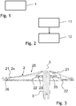
- Fig. 1 shows a flow diagram of a method according to the invention for producing a joining part for an assembly.
- This in Fig. 1 1 shows a method for producing a joining part for an assembly, which can be produced from the joining part and at least one further joining part by means of thermal joining, comprises a step 1, in which one or more functional surface (s) of the joining part with a deviation from a predetermined target value for the functional surface (s) are formed, which is provided after the thermal joining of an end module.
- Fig. 2 shows a flow diagram of a method according to the invention for producing an assembly of a joining part and at least one further joining part.
- the method shown in FIG. 2 for producing an assembly comprising a joining part and at least one further joining part comprises a step 11, in which the joining part and the at least one further joining part are provided, which each have one or more functional surfaces with a deviation from a respective one predetermined setpoint for the respective functional surfaces are formed, which is provided in each case after the thermal joining of an end module.
- the step 11 is followed by a step 12, in which the joining part and the at least one further joining part are thermally joined at predetermined joint surfaces.
- Fig. 3 shows a sectional view of an assembly made according to the in Fig. 2 shown method.
- the assembly is a drum flange for rotatably supporting a drum in a washing machine. Cutting edges are shown as hatched areas.
- the assembly has a connecting flange 2 and a drive shaft 3.
- the connecting flange 2 has a main element 21 with an arm 2a, a support element 22 and a further support element 23, which are formed from stamped sheet metal, in particular steel sheets, preferably made of stainless steel. These three elements 21, 22, 23 are stacked on a longitudinal axis L and connected to the drive shaft 3. At the outer end of the arm 2a, a connecting element 26 is indicated, with which the connecting flange 2 with the drum (not shown) is connected.
- One of the drum (not shown) facing flange back side 25 of the stub shaft device is formed by a surface of the main element 21. It is convex and, when attached to the drum (not shown), conforms to a concave cavity of a drum bottom (not shown).
- the drive shaft 3 is cylindrical and extends along the longitudinal axis L.
- the longitudinal axis L is equal to an axis of rotation about which the drum (not shown) rotates.
- the drum flange is as an assembly of the drive shaft 3 as a joining part and the connecting flange 2, which has the elements 21, 22, 23 as joining parts, by means of in Fig. 1 and 2 produced method produced.
- in Fig. 1 shown method, so that the corresponding joining parts are manufactured and provided, what the in Fig. 2 followed method shows.
Landscapes
- Engineering & Computer Science (AREA)
- Physics & Mathematics (AREA)
- Optics & Photonics (AREA)
- Mechanical Engineering (AREA)
- Plasma & Fusion (AREA)
- Manufacture Of Motors, Generators (AREA)
Applications Claiming Priority (1)
| Application Number | Priority Date | Filing Date | Title |
|---|---|---|---|
| DE102018109842.1A DE102018109842A1 (de) | 2018-04-24 | 2018-04-24 | Verfahren zur Herstellung eines Fügeteils für eine Baugruppe und Verfahren zur Herstellung einer Baugruppe aus einem Fügeteil und zumindest einem weiteren Fügeteil |
Publications (1)
| Publication Number | Publication Date |
|---|---|
| EP3572182A1 true EP3572182A1 (fr) | 2019-11-27 |
Family
ID=66217796
Family Applications (1)
| Application Number | Title | Priority Date | Filing Date |
|---|---|---|---|
| EP19169565.9A Withdrawn EP3572182A1 (fr) | 2018-04-24 | 2019-04-16 | Procédé de fabrication d'un élément d'assemblage pour un module et procédé de fabrication d'un module à partir d'un élément d'assemblage et d'au moins un élément d'assemblage supplémentaire |
Country Status (2)
| Country | Link |
|---|---|
| EP (1) | EP3572182A1 (fr) |
| DE (1) | DE102018109842A1 (fr) |
Citations (4)
| Publication number | Priority date | Publication date | Assignee | Title |
|---|---|---|---|---|
| DE19532783A1 (de) * | 1994-09-06 | 1996-03-07 | Miele & Cie | Vorrichtung zur drehbaren Lagerung einer Trommel einer Trommelwaschmaschine mit einem Tragstern |
| JP2005088048A (ja) * | 2003-09-17 | 2005-04-07 | Toshiba Plant Systems & Services Corp | 配管継手用溶接歪吸収フランジおよび配管継手 |
| JP2007260691A (ja) * | 2006-03-27 | 2007-10-11 | Tokyu Car Corp | パネルの成形方法 |
| US20080262799A1 (en) * | 2004-03-29 | 2008-10-23 | Hidekazu Murakawa | Welding Deformation Computing Method, Welding Deformation Computing Device, and Computer Program Product |
Family Cites Families (1)
| Publication number | Priority date | Publication date | Assignee | Title |
|---|---|---|---|---|
| US20090206065A1 (en) * | 2006-06-20 | 2009-08-20 | Jean-Pierre Kruth | Procedure and apparatus for in-situ monitoring and feedback control of selective laser powder processing |
-
2018
- 2018-04-24 DE DE102018109842.1A patent/DE102018109842A1/de active Pending
-
2019
- 2019-04-16 EP EP19169565.9A patent/EP3572182A1/fr not_active Withdrawn
Patent Citations (4)
| Publication number | Priority date | Publication date | Assignee | Title |
|---|---|---|---|---|
| DE19532783A1 (de) * | 1994-09-06 | 1996-03-07 | Miele & Cie | Vorrichtung zur drehbaren Lagerung einer Trommel einer Trommelwaschmaschine mit einem Tragstern |
| JP2005088048A (ja) * | 2003-09-17 | 2005-04-07 | Toshiba Plant Systems & Services Corp | 配管継手用溶接歪吸収フランジおよび配管継手 |
| US20080262799A1 (en) * | 2004-03-29 | 2008-10-23 | Hidekazu Murakawa | Welding Deformation Computing Method, Welding Deformation Computing Device, and Computer Program Product |
| JP2007260691A (ja) * | 2006-03-27 | 2007-10-11 | Tokyu Car Corp | パネルの成形方法 |
Also Published As
| Publication number | Publication date |
|---|---|
| DE102018109842A1 (de) | 2019-10-24 |
Similar Documents
| Publication | Publication Date | Title |
|---|---|---|
| DE19861391B4 (de) | Verfahren zum Formen einer Nabenscheibe und Drückrolle zur Verwendung beim Formen einer Nabenscheibe | |
| DE4234116C2 (de) | Schwingungsdämpfungseinrichtung | |
| EP3685052B1 (fr) | Assemblage par rivet et procédé de fabrication d'un assemblage par rivet | |
| WO2018033270A1 (fr) | Procédé pour la fabrication d'un ensemble palier de bras de suspension d'un véhicule à moteur et ensemble palier | |
| DE112009003609T5 (de) | Verfahren zum herstellen eines rohrförmigen bauteils | |
| WO2007045203A1 (fr) | Unite de palier, notamment unite de palier de roue destinee a un vehicule et procede de fabrication | |
| DE102005026713A1 (de) | Verfahren zur Verbindung einer Wellenkomponente mit einer Nabenkomponente und Welle-Nabe-Zusammenbau | |
| DE102013108097B4 (de) | Verfahren zur Fertigung eines Kraftmesskörpers | |
| DE1752629A1 (de) | Verfahren und Vorrichtung zum Abrunden von Rohren | |
| DD149390A5 (de) | Siebtrommel und verfahren zu deren herstellung | |
| EP0385176B1 (fr) | Dispositif de poids d'équilibrage pour arbre de transmission à joint de Cardan | |
| EP3572182A1 (fr) | Procédé de fabrication d'un élément d'assemblage pour un module et procédé de fabrication d'un module à partir d'un élément d'assemblage et d'au moins un élément d'assemblage supplémentaire | |
| DE102014019211A1 (de) | Verfahren und Vorrichtung zum Herstellen einer Fügeverbindung | |
| DE102007009779A1 (de) | Drehverbindung zwischen Welle und Ritzel und Verfahren zu deren Herstellung | |
| EP3237241B1 (fr) | Combinaison d'un bras de suspension et d'un tube d'essieu, et procédé de fabrication d'un bras de suspension fixé à un tube d'essieu. | |
| WO2017013099A1 (fr) | Installation et procédé destinés à l'élimination de défauts de planéité d'un produit plat métallique | |
| DE102017108218A1 (de) | Höhenverstelleinrichtung eines Kraftfahrzeugsitzes sowie Verfahren zur Herstellung einer derartigen Höhenverstelleinrichtung | |
| DE102007025325A1 (de) | Zusammenbaueinheit aus einer Gleichlaufgelenknabe und einer Profilwelle und Verfahren zur Herstellung einer solchen | |
| DE102005050198B4 (de) | Verfahren zur Herstellung von Bauteilen mit partiellen Verstärkungselementen | |
| DE102009022935A1 (de) | Vorrichtung zum gezielten Verformen von Längsträgern von Kraftfahrzeugen | |
| EP3858512B1 (fr) | Dispositif de pliage destiné à l'usinage par pliage d'un module de tôle | |
| DE10308008A1 (de) | Zylindervorrichtung und Verfahren zur Herstellung einer Kolbenstange für die Zylindervorrichtung | |
| DE102018219463A1 (de) | Applikationsvorrichtung zum Auftragen von mindestens einem Klebstoff und Verfahren zum Herstellen einer kombinierten Falz-Klebeverbindung | |
| BE1030972B1 (de) | Verfahren zur Herstellung einer Verbindung zwischen einer Welle und einer Gelenkgabel eines Lenksystems für ein Kraftfahrzeug und Lenksystem für ein Kraftfahrzeug | |
| WO2019001963A1 (fr) | Procédé pour la fabrication d'un palier à patins oscillants et palier à patins oscillants |
Legal Events
| Date | Code | Title | Description |
|---|---|---|---|
| PUAI | Public reference made under article 153(3) epc to a published international application that has entered the european phase |
Free format text: ORIGINAL CODE: 0009012 |
|
| STAA | Information on the status of an ep patent application or granted ep patent |
Free format text: STATUS: THE APPLICATION HAS BEEN PUBLISHED |
|
| AK | Designated contracting states |
Kind code of ref document: A1 Designated state(s): AL AT BE BG CH CY CZ DE DK EE ES FI FR GB GR HR HU IE IS IT LI LT LU LV MC MK MT NL NO PL PT RO RS SE SI SK SM TR |
|
| AX | Request for extension of the european patent |
Extension state: BA ME |
|
| STAA | Information on the status of an ep patent application or granted ep patent |
Free format text: STATUS: REQUEST FOR EXAMINATION WAS MADE |
|
| 17P | Request for examination filed |
Effective date: 20200527 |
|
| RBV | Designated contracting states (corrected) |
Designated state(s): AL AT BE BG CH CY CZ DE DK EE ES FI FR GB GR HR HU IE IS IT LI LT LU LV MC MK MT NL NO PL PT RO RS SE SI SK SM TR |
|
| STAA | Information on the status of an ep patent application or granted ep patent |
Free format text: STATUS: EXAMINATION IS IN PROGRESS |
|
| STAA | Information on the status of an ep patent application or granted ep patent |
Free format text: STATUS: EXAMINATION IS IN PROGRESS |
|
| 17Q | First examination report despatched |
Effective date: 20201104 |
|
| STAA | Information on the status of an ep patent application or granted ep patent |
Free format text: STATUS: THE APPLICATION HAS BEEN WITHDRAWN |
|
| 18W | Application withdrawn |
Effective date: 20210506 |