EP3572182A1 - Method of producing a joint for an assembly and method of manufacturing an assembly consisting of a joint and at least one further joint - Google Patents
Method of producing a joint for an assembly and method of manufacturing an assembly consisting of a joint and at least one further joint Download PDFInfo
- Publication number
- EP3572182A1 EP3572182A1 EP19169565.9A EP19169565A EP3572182A1 EP 3572182 A1 EP3572182 A1 EP 3572182A1 EP 19169565 A EP19169565 A EP 19169565A EP 3572182 A1 EP3572182 A1 EP 3572182A1
- Authority
- EP
- European Patent Office
- Prior art keywords
- joining part
- joining
- assembly
- thermal
- producing
- Prior art date
- Legal status (The legal status is an assumption and is not a legal conclusion. Google has not performed a legal analysis and makes no representation as to the accuracy of the status listed.)
- Withdrawn
Links
Images
Classifications
-
- B—PERFORMING OPERATIONS; TRANSPORTING
- B23—MACHINE TOOLS; METAL-WORKING NOT OTHERWISE PROVIDED FOR
- B23K—SOLDERING OR UNSOLDERING; WELDING; CLADDING OR PLATING BY SOLDERING OR WELDING; CUTTING BY APPLYING HEAT LOCALLY, e.g. FLAME CUTTING; WORKING BY LASER BEAM
- B23K26/00—Working by laser beam, e.g. welding, cutting or boring
- B23K26/20—Bonding
- B23K26/21—Bonding by welding
- B23K26/24—Seam welding
- B23K26/28—Seam welding of curved planar seams
-
- B—PERFORMING OPERATIONS; TRANSPORTING
- B23—MACHINE TOOLS; METAL-WORKING NOT OTHERWISE PROVIDED FOR
- B23K—SOLDERING OR UNSOLDERING; WELDING; CLADDING OR PLATING BY SOLDERING OR WELDING; CUTTING BY APPLYING HEAT LOCALLY, e.g. FLAME CUTTING; WORKING BY LASER BEAM
- B23K26/00—Working by laser beam, e.g. welding, cutting or boring
- B23K26/20—Bonding
- B23K26/32—Bonding taking account of the properties of the material involved
-
- B—PERFORMING OPERATIONS; TRANSPORTING
- B23—MACHINE TOOLS; METAL-WORKING NOT OTHERWISE PROVIDED FOR
- B23K—SOLDERING OR UNSOLDERING; WELDING; CLADDING OR PLATING BY SOLDERING OR WELDING; CUTTING BY APPLYING HEAT LOCALLY, e.g. FLAME CUTTING; WORKING BY LASER BEAM
- B23K31/00—Processes relevant to this subclass, specially adapted for particular articles or purposes, but not covered by only one of the preceding main groups
- B23K31/003—Processes relevant to this subclass, specially adapted for particular articles or purposes, but not covered by only one of the preceding main groups relating to controlling of welding distortion
-
- B—PERFORMING OPERATIONS; TRANSPORTING
- B23—MACHINE TOOLS; METAL-WORKING NOT OTHERWISE PROVIDED FOR
- B23K—SOLDERING OR UNSOLDERING; WELDING; CLADDING OR PLATING BY SOLDERING OR WELDING; CUTTING BY APPLYING HEAT LOCALLY, e.g. FLAME CUTTING; WORKING BY LASER BEAM
- B23K31/00—Processes relevant to this subclass, specially adapted for particular articles or purposes, but not covered by only one of the preceding main groups
- B23K31/02—Processes relevant to this subclass, specially adapted for particular articles or purposes, but not covered by only one of the preceding main groups relating to soldering or welding
-
- B—PERFORMING OPERATIONS; TRANSPORTING
- B23—MACHINE TOOLS; METAL-WORKING NOT OTHERWISE PROVIDED FOR
- B23K—SOLDERING OR UNSOLDERING; WELDING; CLADDING OR PLATING BY SOLDERING OR WELDING; CUTTING BY APPLYING HEAT LOCALLY, e.g. FLAME CUTTING; WORKING BY LASER BEAM
- B23K2101/00—Articles made by soldering, welding or cutting
- B23K2101/04—Tubular or hollow articles
-
- B—PERFORMING OPERATIONS; TRANSPORTING
- B23—MACHINE TOOLS; METAL-WORKING NOT OTHERWISE PROVIDED FOR
- B23K—SOLDERING OR UNSOLDERING; WELDING; CLADDING OR PLATING BY SOLDERING OR WELDING; CUTTING BY APPLYING HEAT LOCALLY, e.g. FLAME CUTTING; WORKING BY LASER BEAM
- B23K2101/00—Articles made by soldering, welding or cutting
- B23K2101/18—Sheet panels
Definitions
- the invention relates to a method for producing a joining part for an assembly and to a method for producing an assembly from a joining part and at least one further joining part.
- the invention relates to a method for producing a joining part for an assembly which can be produced from the joining part and at least one further joining part by means of thermal joining, and a method for producing an assembly from a joining part and at least one further joining part by means of thermal joining.
- thermal joining methods such as a welding method
- joining parts which are assembled into a subassembly tend to distort under the influence of heat.
- thermal joining methods such as a welding method
- the components are pre-positioned before the thermal joining process in accordance with an expected delay in the opposite direction. This is possibly associated with additional entry of residual stresses in the assembly, especially if the parts to be joined have already been connected in advance via a joining method or several process steps for connecting several individual parts to be joined to produce an end module are required.
- Another way to compensate for the thermal distortion is a downstream straightening process, this can be done mechanically or via a targeted thermal energy input.
- Downstream measurements can be used to determine a distortion characteristic.
- a corresponding welding gap greater than or equal to 0 mm is required, so that an adjustment of the joining parts to be joined ie the joining partner can be made possible.
- the joining partners were already connected in advance by a joint seam, a high force is required to achieve this bias of the joining partners. This in turn leads to an inevitable stress introduction into the existing joint.
- the movement ensures that the joining gap to be joined varies and circumferentially varies in size. This is particularly problematic in connection with a laser welding process, since the area of energy input is particularly small here and too different Can lead seam qualities. Under certain circumstances, even a collapse of the seam is possible, which can cause a serious defect.
- the invention thus presents the problem of providing a method for producing a component to be joined for an assembly and methods for producing an assembly of a joining part and at least one further joining part, which lead to a final assembly produced by a thermal joining process with high final accuracy.
- the achievable with the present invention consist in the fact that the individual joining parts to be joined for the production of the assembly no longer have to be braced against each other and a circumferentially uniform gap in the thermal joining process for the production of the assembly can be ensured. Furthermore, an additional introduction of residual stresses is avoided, and a seam quality is increased. In addition, costs are reduced.
- the invention relates to a method for producing a joining part for an assembly, which can be produced from the joining part and at least one further joining part by means of thermal joining, comprising the following step forming one or more functional surface (s) of the joining part with a deviation from a predetermined desired value for the Functional surface (s) provided after the thermal joining of an end assembly.
- the joining part or parts are produced prior to the thermal joining process for producing the assembly with warped or distorted functional surfaces such that an end assembly with high final accuracy can be produced by utilizing the distortion occurring during the thermal joining process.
- the assembly may be the end assembly.
- the module produced from the joining part and the at least one further joining part is not the end module but is itself further used as a joining part in a further thermal joining method.
- each functional surface has its respective deviation and its respective predetermined desired value.
- the method further comprises the step of providing a data value for the deviation.
- the data value is preferably based on an empirical determination of the deviation. That is, the adherend and the at least one further adherend undergo one or more thermal joining processes, and the resulting distortion of the end assembly is determined empirically. From this, the respective deviation can be determined empirically and the respective data value can be provided. If joining parts are thermally joined, subsequent measurements can be used to determine the distortion characteristic of the assembly. From this, the data value for the deviation can be empirically determined and optimized.
- the data value preferably represents an average value of a plurality of individual data values, which have each been determined empirically from a single thermal joining process for producing the end assembly from the joining part with the at least one further joining part. As a result, the final accuracy of the end module can be increased.
- the invention relates to a method for producing an assembly from a joining part and at least one further joining part, comprising the following steps providing the joining part, which has one or more functional surface (s) formed with a deviation from a predetermined desired value, which after thermal joining of an end module is provided, and the at least one further joining part; and thermal joining of the joining part and the at least one further joining part at predetermined joining surfaces.
- an additional tightening and pre-positioning of the joining part and the at least one further joining part can be prevented.
- no complex clamping systems are required and the additional entry of residual stresses in the module to be joined thermally is prevented.
- the quality and durability can be increased.
- there is no change in the joint gap more which inevitably leads to a circumferentially different seam and connection quality.
- the required joint gap can be reduced to a minimum, which in turn makes the process more robust and saves costs (e.g., reduced use of filler wire).
- the at least one further joining part may also, just like the joining part, have one or more functional surfaces, which are formed with a deviation from a predetermined desired value, which is provided in each case after the thermal joining of an end subassembly is.
- each functional surface preferably has its respective deviation and its respective predetermined nominal value.
- the step of providing the joining part and possibly the at least one further joining part preferably comprises carrying out the above-described method for producing a joining part for an assembly, wherein one or more functional surface (s) of the joining part with a deviation from a predetermined setpoint for the functional surface (s) are formed, which is provided after the thermal joining of an end module.
- the thermal joining preferably comprises a welding process, more preferably a laser welding process.
- the joining part and the at least one further joining part are connected to one or more welds.
- the process is carried out stress-free and pre-positioning device free. This will continue to save costs.
- the assembly is a drum flange preferred Brasstrommelflansch a washing machine.
- the term "washing machine” includes a washing machine and a combination device such as a washer-dryer.
- the drum flange serves to rotatably support a drum in the washing machine. It has a flange and a drive shaft. Since the drum must be free to the washing machine opening, the attachment of the drum can only be done at the rear end, so on the circular drum base.
- the flange connects the drum base with the drive shaft of a drive device, which in turn is responsible for the rotary drive of the drum.
- the drum flange must transmit the torque of the drive device from the drive shaft to the drum and be able to absorb all forces due to any imbalance forces the drum can.
- the drum flange is therefore a heavily loaded assembly, at the joining parts and joints high demands. Since it must be fitted into the washing machine with limited space, it must be manufactured with a high final accuracy.
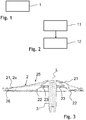
- Fig. 1 shows a flow diagram of a method according to the invention for producing a joining part for an assembly.
- This in Fig. 1 1 shows a method for producing a joining part for an assembly, which can be produced from the joining part and at least one further joining part by means of thermal joining, comprises a step 1, in which one or more functional surface (s) of the joining part with a deviation from a predetermined target value for the functional surface (s) are formed, which is provided after the thermal joining of an end module.
- Fig. 2 shows a flow diagram of a method according to the invention for producing an assembly of a joining part and at least one further joining part.
- the method shown in FIG. 2 for producing an assembly comprising a joining part and at least one further joining part comprises a step 11, in which the joining part and the at least one further joining part are provided, which each have one or more functional surfaces with a deviation from a respective one predetermined setpoint for the respective functional surfaces are formed, which is provided in each case after the thermal joining of an end module.
- the step 11 is followed by a step 12, in which the joining part and the at least one further joining part are thermally joined at predetermined joint surfaces.
- Fig. 3 shows a sectional view of an assembly made according to the in Fig. 2 shown method.
- the assembly is a drum flange for rotatably supporting a drum in a washing machine. Cutting edges are shown as hatched areas.
- the assembly has a connecting flange 2 and a drive shaft 3.
- the connecting flange 2 has a main element 21 with an arm 2a, a support element 22 and a further support element 23, which are formed from stamped sheet metal, in particular steel sheets, preferably made of stainless steel. These three elements 21, 22, 23 are stacked on a longitudinal axis L and connected to the drive shaft 3. At the outer end of the arm 2a, a connecting element 26 is indicated, with which the connecting flange 2 with the drum (not shown) is connected.
- One of the drum (not shown) facing flange back side 25 of the stub shaft device is formed by a surface of the main element 21. It is convex and, when attached to the drum (not shown), conforms to a concave cavity of a drum bottom (not shown).
- the drive shaft 3 is cylindrical and extends along the longitudinal axis L.
- the longitudinal axis L is equal to an axis of rotation about which the drum (not shown) rotates.
- the drum flange is as an assembly of the drive shaft 3 as a joining part and the connecting flange 2, which has the elements 21, 22, 23 as joining parts, by means of in Fig. 1 and 2 produced method produced.
- in Fig. 1 shown method, so that the corresponding joining parts are manufactured and provided, what the in Fig. 2 followed method shows.
Abstract
Die Erfindung betrifft ein Verfahren zur Herstellung eines Fügeteils (2) für eine Baugruppe, welche aus dem Fügeteil (2) und zumindest einem weiteren Fügeteil (3) mittels thermischen Fügens herstellbar ist, aufweisend folgenden Schritt Ausbilden einer oder mehrerer Funktionsfläche(n) des Fügeteils (2) mit einer Abweichung von einem vorbestimmten Sollwert für die Funktionsfläche(n), der nach dem thermischen Fügen einer Endbaugruppe vorgesehen ist. Ferner betrifft die Erfindung ein Verfahren zur Herstellung einer Baugruppe aus einem Fügeteil (2) und zumindest einem weiteren Fügeteil (3), aufweisend folgende Schritte Bereitstellen des Fügeteils (2) und des zumindest einen weiteren Fügeteils (3), welche jeweils eine oder mehrere Funktionsflächen aufweisen, die mit jeweils einer Abweichung von einem jeweilig vorbestimmten Sollwert für die jeweilige Funktionsflächen ausgebildet sind, der jeweils nach dem thermischen Fügen einer Endbaugruppe vorgesehen ist; und thermisches Fügen des Fügeteils (2) und des zumindest einem weiteren Fügeteils (3) an vorbestimmten Fügeflächen.The invention relates to a method for producing a joining part (2) for an assembly which can be produced from the joining part (2) and at least one further joining part (3) by means of thermal joining, having the following step of forming one or more functional surface (s) of the joining part (2) with a deviation from a predetermined target value for the functional surface (s), which is provided after the thermal joining of an end assembly. The invention also relates to a method for producing an assembly from a joining part (2) and at least one further joining part (3), having the following steps: providing the joining part (2) and the at least one further joining part (3), each of which has one or more functional surfaces which are each formed with a deviation from a respective predetermined setpoint value for the respective functional surfaces, which is provided after the thermal joining of an end assembly; and thermal joining of the joining part (2) and the at least one further joining part (3) at predetermined joining surfaces.
Description
Die Erfindung betrifft ein Verfahren zur Herstellung eines Fügeteils für eine Baugruppe und ein Verfahren zur Herstellung einer Baugruppe aus einem Fügeteil und zumindest einem weiteren Fügeteil. Insbesondere betrifft die Erfindung ein Verfahren zur Herstellung eines Fügeteils für eine Baugruppe, welche aus dem Fügeteil und zumindest einem weiteren Fügeteil mittels thermischen Fügens herstellbar ist, und ein Verfahren zur Herstellung einer Baugruppe aus einem Fügeteil und zumindest einem weiteren Fügeteil mittels thermischen Fügens.The invention relates to a method for producing a joining part for an assembly and to a method for producing an assembly from a joining part and at least one further joining part. In particular, the invention relates to a method for producing a joining part for an assembly which can be produced from the joining part and at least one further joining part by means of thermal joining, and a method for producing an assembly from a joining part and at least one further joining part by means of thermal joining.
Bei der Anwendung von thermischen Fügeverfahren wie einem Schweißverfahren neigen Fügeteile, die zu einer Baugruppe zusammengefügt werden, dazu, sich unter dem thermischen Einfluss zu verziehen. Derzeit gibt es nach einem druckschriftlich nicht belegten Stand der Technik mehrere Möglichkeiten diesen Verzug zu reduzieren oder zu kompensieren. Beispielsweise werden die Bauteile vor dem thermischen Fügeverfahren entsprechend einem zu erwartenden Verzug in entgegen gerichteter Richtung vorpositioniert. Dies ist unter Umständen mit zusätzlichem Eintrag von Eigenspannungen in die Baugruppe verbunden, insbesondere dann, wenn die Fügeteile im Vorfeld bereits über ein Fügeverfahren verbunden worden sind bzw. mehrere Prozessschritte zur Verbindung von mehreren einzelnen Fügeteilen zur Herstellung einer Endbaugruppe erforderlich sind. Eine weitere Möglichkeit zur Kompensation des thermischen Verzuges ist ein nachgeschalteter Richtprozess, dieser kann mechanisch oder auch über einen gezielten thermischen Energieeintrag erfolgen.When using thermal joining methods such as a welding method, joining parts which are assembled into a subassembly tend to distort under the influence of heat. At present, there are several options for reducing or compensating for this delay according to a prior art document which has not been printed. For example, the components are pre-positioned before the thermal joining process in accordance with an expected delay in the opposite direction. This is possibly associated with additional entry of residual stresses in the assembly, especially if the parts to be joined have already been connected in advance via a joining method or several process steps for connecting several individual parts to be joined to produce an end module are required. Another way to compensate for the thermal distortion is a downstream straightening process, this can be done mechanically or via a targeted thermal energy input.
Durch nachgeschaltete Messungen lässt sich eine Verzugsausprägung bestimmen. So besteht die Möglichkeit alle folgenden Baugruppen dahingehend vorzuspannen, nämlich entgegen der Verzugsrichtung, sodass die erforderliche Maßhaltigkeit des Bauteils nach dem thermischen Fügeverfahren eingehalten werden kann (iterativer Prozess). Dafür wird ein entsprechender Schweißspalt größer gleich 0 mm benötigt, sodass eine Verstellung der zu fügenden Fügeteile d.h. der Fügepartner ermöglicht werden kann. Da die Fügepartner bereits im Vorfeld durch eine Fügenaht verbunden wurden, ist eine hohe Kraft erforderlich, um diese Vorspannung der Fügepartner zu erreichen. Dies führt wiederum zu einer zwangsläufigen Spannungseinbringung in die bestehende Fügestelle. Zusätzlich sorgt die Bewegung dafür, dass der zu fügende Fügespalt variiert und umlaufend unterschiedlich groß wird. Dies ist insbesondere im Zusammenhang mit einem Laserschweißprozess problematisch, da der Bereich der Energieeinbringung hier besonders klein ist und zu unterschiedlichen Nahtqualitäten führen kann. Unter Umständen ist sogar ein Einfallen der Naht möglich, welches eine gravierende Fehlstelle hervorrufen kann.Downstream measurements can be used to determine a distortion characteristic. Thus, it is possible to prestress all the following subassemblies, namely counter to the direction of delay, so that the required dimensional accuracy of the component can be maintained after the thermal joining process (iterative process). For this purpose, a corresponding welding gap greater than or equal to 0 mm is required, so that an adjustment of the joining parts to be joined ie the joining partner can be made possible. Since the joining partners were already connected in advance by a joint seam, a high force is required to achieve this bias of the joining partners. This in turn leads to an inevitable stress introduction into the existing joint. In addition, the movement ensures that the joining gap to be joined varies and circumferentially varies in size. This is particularly problematic in connection with a laser welding process, since the area of energy input is particularly small here and too different Can lead seam qualities. Under certain circumstances, even a collapse of the seam is possible, which can cause a serious defect.
Es besteht daher weiterhin ein Bedarf einen thermischen Verzug der Baugruppe zu kompensieren, der zu einer erheblichen Abweichung der erforderlichen Endgenauigkeit führt.There is therefore still a need to compensate for a thermal distortion of the assembly, which leads to a significant deviation of the required final accuracy.
Der Erfindung stellt sich somit das Problem, ein Verfahren zur Herstellung eines Fügeteils für eine Baugruppe und Verfahren zur Herstellung einer Baugruppe aus einem Fügeteil und zumindest einem weiteren Fügeteil bereit zu stellen, die zu einer mittels eines thermischen Fügeverfahrens hergestellten Endbaugruppe mit hoher Endgenauigkeit führen.The invention thus presents the problem of providing a method for producing a component to be joined for an assembly and methods for producing an assembly of a joining part and at least one further joining part, which lead to a final assembly produced by a thermal joining process with high final accuracy.
Erfindungsgemäß wird dieses Problem durch ein Verfahren mit den Merkmalen des Patentanspruchs 1 und ein Verfahren mit den Merkmalen des Patentanspruchs 5 gelöst. Vorteilhafte Ausgestaltungen und Weiterbildungen der Erfindung ergeben sich aus den nachfolgenden Unteransprüchen.According to the invention, this problem is solved by a method having the features of
Die mit der Erfindung erreichbaren Vorteile bestehen darin, dass die zur Herstellung der Baugruppe zu fügenden einzelnen Fügeteile nicht mehr gegeneinander verspannt werden müssen und ein umlaufend gleichbleibender Spalt bei dem thermischen Fügeverfahren zur Herstellung der Baugruppe gewährleistet werden kann. Weiterhin wird eine zusätzliche Einbringung von Eigenspannungen vermieden, und eine Nahtqualität wird gesteigert. Zudem werden Kosten reduziert.The achievable with the present invention consist in the fact that the individual joining parts to be joined for the production of the assembly no longer have to be braced against each other and a circumferentially uniform gap in the thermal joining process for the production of the assembly can be ensured. Furthermore, an additional introduction of residual stresses is avoided, and a seam quality is increased. In addition, costs are reduced.
Die Erfindung betrifft ein Verfahren zur Herstellung eines Fügeteils für eine Baugruppe, welche aus dem Fügeteil und zumindest einem weiteren Fügeteil mittels thermischen Fügens herstellbar ist, aufweisend folgenden Schritt Ausbilden einer oder mehrerer Funktionsfläche(n) des Fügeteils mit einer Abweichung von einem vorbestimmten Sollwert für die Funktionsfläche(n), der nach dem thermischen Fügen einer Endbaugruppe vorgesehen ist.The invention relates to a method for producing a joining part for an assembly, which can be produced from the joining part and at least one further joining part by means of thermal joining, comprising the following step forming one or more functional surface (s) of the joining part with a deviation from a predetermined desired value for the Functional surface (s) provided after the thermal joining of an end assembly.
Anders ausgedrückt, wird das Fügeteil oder werden die Fügeteile vor dem thermischen Fügeverfahren zur Herstellung der Baugruppe mit derart verzogener oder verzogenen Funktionsflächen hergestellt, dass unter Ausnutzung des während des thermischen Fügeverfahrens auftretenden Verzuges eine Endbaugruppe mit hoher Endgenauigkeit erzeugt werden kann.In other words, the joining part or parts are produced prior to the thermal joining process for producing the assembly with warped or distorted functional surfaces such that an end assembly with high final accuracy can be produced by utilizing the distortion occurring during the thermal joining process.
Die Baugruppe kann die Endbaugruppe sein. Alternativ ist die aus dem Fügeteil und dem zumindest einem weiteren Fügeteil hergestellte Baugruppe nicht die Endbaugruppe sondern wird selbst als Fügeteil in einem weiteren thermischen Fügeverfahren weiter verwendet.The assembly may be the end assembly. Alternatively, the module produced from the joining part and the at least one further joining part is not the end module but is itself further used as a joining part in a further thermal joining method.
Im Falle der Ausbildung mehrerer Funktionsflächen des Fügeteils mit einer Abweichung von einem vorbestimmten Sollwert für die Funktionsflächen weist jede Funktionsfläche ihre jeweilige Abweichung und ihren jeweiligen vorbestimmten Sollwert auf.In the case of the formation of a plurality of functional surfaces of the joining part with a deviation from a predetermined desired value for the functional surfaces, each functional surface has its respective deviation and its respective predetermined desired value.
In einer bevorzugten Ausführungsform weist das Verfahren weiterhin folgenden Schritt Bereitstellen eines Datenwerts für die Abweichung auf. Bevorzugt basiert der Datenwert auf einer empirischen Ermittlung der Abweichung. D.h., das Fügeteil und das zumindest eine weitere Fügeteil werden einem oder mehreren thermischen Fügeverfahren unterzogen, und der sich einstellende Verzug der Endbaugruppe wird empirisch ermittelt. Daraus kann die jeweilige Abweichung empirisch ermittelt werden und der jeweilige Datenwert bereitgestellt werden. Wenn Fügeteile thermisch gefügt werden, lässt sich durch nachgeschaltete Messungen die Verzugsausprägung der Baugruppe bestimmen. Daraus kann der Datenwert für die Abweichung empirisch ermittelt und optimiert werden.In a preferred embodiment, the method further comprises the step of providing a data value for the deviation. The data value is preferably based on an empirical determination of the deviation. That is, the adherend and the at least one further adherend undergo one or more thermal joining processes, and the resulting distortion of the end assembly is determined empirically. From this, the respective deviation can be determined empirically and the respective data value can be provided. If joining parts are thermally joined, subsequent measurements can be used to determine the distortion characteristic of the assembly. From this, the data value for the deviation can be empirically determined and optimized.
Bevorzugt stellt der Datenwert einen Mittelwert von mehreren Einzeldatenwerten dar, die jeweils aus einem einzelnen thermischen Fügevorgang zur Herstellung der Endbaugruppe aus dem Fügeteil mit dem zumindest einem weiteren Fügeteil empirisch ermittelt worden sind. Dadurch kann die Endgenauigkeit der Endbaugruppe erhöht werden.The data value preferably represents an average value of a plurality of individual data values, which have each been determined empirically from a single thermal joining process for producing the end assembly from the joining part with the at least one further joining part. As a result, the final accuracy of the end module can be increased.
Ferner betrifft die Erfindung ein Verfahren zur Herstellung einer Baugruppe aus einem Fügeteil und zumindest einem weiteren Fügeteil, aufweisend folgende Schritte Bereitstellen des Fügeteils, welches eine oder mehrere Funktionsfläche(n) aufweist, die mit einer Abweichung von einem vorbestimmten Sollwert ausgebildet sind, der nach dem thermischen Fügen einer Endbaugruppe vorgesehen ist, und des zumindest einen weiteren Fügeteils; und thermisches Fügen des Fügeteils und des zumindest einem weiteren Fügeteils an vorbestimmten Fügeflächen.Furthermore, the invention relates to a method for producing an assembly from a joining part and at least one further joining part, comprising the following steps providing the joining part, which has one or more functional surface (s) formed with a deviation from a predetermined desired value, which after thermal joining of an end module is provided, and the at least one further joining part; and thermal joining of the joining part and the at least one further joining part at predetermined joining surfaces.
Durch das erfindungsgemäße Verfahren kann ein zusätzliches Spannen und Vorpositionieren des Fügeteils und des zumindest einen weiteren Fügeteils unterbunden werden. Dadurch werden keine aufwändigen Spannsysteme benötigt und der zusätzliche Eintrag von Eigenspannungen in die thermisch zu fügende Baugruppe wird verhindert. Dadurch kann die Qualität und Betriebsfestigkeit gesteigert werden. Zusätzlich erfolgt keine Veränderung des Fügespalts mehr, der unweigerlich zu einer umlaufend unterschiedlichen Naht- und Anbindungsqualität führt. Zusätzlich kann der benötigte Fügespalt auf ein Minimum reduziert werden, was wiederum das Verfahren robuster macht und Kosten einspart (z.B. reduzierter Einsatz von Zusatzdraht).The inventive method, an additional tightening and pre-positioning of the joining part and the at least one further joining part can be prevented. As a result, no complex clamping systems are required and the additional entry of residual stresses in the module to be joined thermally is prevented. As a result, the quality and durability can be increased. In addition, there is no change in the joint gap more, which inevitably leads to a circumferentially different seam and connection quality. In addition, the required joint gap can be reduced to a minimum, which in turn makes the process more robust and saves costs (e.g., reduced use of filler wire).
Das zumindest eine weitere Fügeteil kann auch genau wie das Fügeteil eine oder mehrere Funktionsflächen aufweisen, die mit einer Abweichung von einem vorbestimmten Sollwert ausgebildet sind, der jeweils nach dem thermischen Fügen einer Endbaugruppe vorgesehen ist. Auch hier weist bevorzugt im Falle der Ausbildung mehrerer Funktionsflächen des Fügeteils oder des weiteren Fügeteils mit einer Abweichung von einem vorbestimmten Sollwert für die Funktionsflächen jede Funktionsfläche ihre jeweilige Abweichung und ihren jeweiligen vorbestimmten Sollwert auf.The at least one further joining part may also, just like the joining part, have one or more functional surfaces, which are formed with a deviation from a predetermined desired value, which is provided in each case after the thermal joining of an end subassembly is. Here, too, in the case of the formation of a plurality of functional surfaces of the joining part or of the further joining part with a deviation from a predetermined desired value for the functional surfaces, each functional surface preferably has its respective deviation and its respective predetermined nominal value.
Der Schritt des Bereitstellens des Fügeteils und ggf. des zumindest einen weiteren Fügeteils weist bevorzugt eine Durchführung des vorstehend beschriebenen Verfahrens zur Herstellung eines Fügeteils für eine Baugruppe auf, bei dem eine oder mehrere Funktionsfläche(n) des Fügeteils mit einer Abweichung von einem vorbestimmten Sollwert für die Funktionsfläche(n) ausgebildet werden, der nach dem thermischen Fügen einer Endbaugruppe vorgesehen ist.The step of providing the joining part and possibly the at least one further joining part preferably comprises carrying out the above-described method for producing a joining part for an assembly, wherein one or more functional surface (s) of the joining part with a deviation from a predetermined setpoint for the functional surface (s) are formed, which is provided after the thermal joining of an end module.
Das thermische Fügen umfasst bevorzugt einen Schweißprozess bevorzugter einen Laserschweißprozess. Das Fügeteil und das zumindest eine weitere Fügeteil werden mit einer oder mehreren Schweißnähten verbunden.The thermal joining preferably comprises a welding process, more preferably a laser welding process. The joining part and the at least one further joining part are connected to one or more welds.
In einer bevorzugten Ausführungsform wird das Verfahren spannvorrichtungsfrei und vorpositioniervorrichtungsfrei durchgeführt. Dadurch werden weiterhin Kosten gespart.In a preferred embodiment, the process is carried out stress-free and pre-positioning device free. This will continue to save costs.
Bevorzugt ist die Baugruppe ein Trommelflansch bevorzugter Edelstahltrommelflansch eines Waschautomaten. Der Ausdruck "Waschautomat" umfasst eine Waschmaschine und ein Kombigerät wie einen Waschtrockner. Der Trommelflansch dient zur drehbaren Lagerung einer Trommel in der Waschmaschine. Er weist einen Flansch und eine Antriebswelle auf. Da die Trommel zur Waschmaschinenöffnung hin frei sein muss, kann die Befestigung der Trommel lediglich am hinteren Ende, also am kreisförmigen Trommelboden erfolgen. Der Flansch verbindet den Trommelboden mit der Antriebswelle einer Antriebsvorrichtung, welche wiederum für den Drehantrieb der Trommel verantwortlich ist. Der Trommelflansch muss das Drehmoment der Antriebsvorrichtung von der Antriebswelle auf die Trommel übertragen und in der Lage sein, alle aufgrund einer etwaigen Unwucht entstehenden Kräfte der Trommel aufnehmen zu können. Der Trommelflansch ist daher eine stark belastete Baugruppe, an deren Fügeteile und Fügenähte hohe Anforderungen bestehen. Da er in die Waschmaschine mit begrenztem Bauraum eingepasst werden muss, ist muss mit einer hohen Endgenauigkeit hergestellt werden.Preferably, the assembly is a drum flange preferred Edelstahltrommelflansch a washing machine. The term "washing machine" includes a washing machine and a combination device such as a washer-dryer. The drum flange serves to rotatably support a drum in the washing machine. It has a flange and a drive shaft. Since the drum must be free to the washing machine opening, the attachment of the drum can only be done at the rear end, so on the circular drum base. The flange connects the drum base with the drive shaft of a drive device, which in turn is responsible for the rotary drive of the drum. The drum flange must transmit the torque of the drive device from the drive shaft to the drum and be able to absorb all forces due to any imbalance forces the drum can. The drum flange is therefore a heavily loaded assembly, at the joining parts and joints high demands. Since it must be fitted into the washing machine with limited space, it must be manufactured with a high final accuracy.
Ein Ausführungsbeispiel der Erfindung ist in den Zeichnungen rein schematisch dargestellt und wird nachfolgend näher beschrieben. Es zeigt schematisch
- Fig. 1
- ein Ablaufdiagramm eines erfindungsgemäßen Verfahrens zur Herstellung eines Fügeteils für eine Baugruppe;
- Fig. 2
- ein Ablaufdiagramm eines erfindungsgemäßen Verfahrens zur Herstellung einer Baugruppe aus einem Fügeteil und zumindest einem weiteren Fügeteil; und
- Fig. 3
- ein Schnittbild einer Baugruppe, hergestellt nach den in
Fig. 1 und 2 gezeigten Verfahren.
- Fig. 1
- a flow diagram of a method according to the invention for producing a joining part for an assembly;
- Fig. 2
- a flow diagram of a method according to the invention for producing an assembly of a joining part and at least one further joining part; and
- Fig. 3
- a sectional view of an assembly made according to the in
Fig. 1 and 2 shown method.
Der Verbindungsflansch 2 weist ein Hauptelement 21 mit einem Arm 2a, ein Stützelement 22 und ein weiteres Stützelement 23 auf, die aus stanzverformten Blechen, insbesondere Stahlblechen gebildet sind, vorzugsweise aus Edelstahl. Diese drei Elemente 21, 22, 23 sind entlang einer Längsachse L aufeinander gestapelt und mit der Antriebswelle 3 verbunden. Am äußeren Ende des Arms 2a ist ein Verbindungselement 26 angedeutet, mit dem der Verbindungsflansch 2 mit der Trommel (nicht gezeigt) verbunden ist. Eine der Trommel (nicht gezeigt) zugewandte Flanschrückseite 25 der Flanschwellenvorrichtung wird durch eine Fläche des Hauptelementes 21 gebildet. Sie ist konvex und schmiegt sich beim Befestigen mit der Trommel (nicht gezeigt) in eine konkave Aushöhlung eines Trommelbodens (nicht gezeigt) ein.The connecting
Die Antriebswelle 3 ist zylindrisch und erstreckt sich entlang der Längsachse L. Im eingebauten Zustand in einer Waschmaschine (nicht dargestellt) ist die Längsachse L gleich eine Drehachse, um welche die Trommel (nicht gezeigt) rotiert.The
Der Trommelflansch ist als Baugruppe aus der Antriebswelle 3 als Fügeteil und dem Verbindungsflansch 2, der die Elemente 21, 22, 23 als Fügeteile aufweist, mittels der in
- LL
- Längsachselongitudinal axis
- 22
- Verbindungsflanschconnecting flange
- 2a2a
- Armpoor
- 2121
- Hauptelementmain element
- 2222
- Stützelementsupport element
- 2323
- weiteres Stützelementanother support element
- 2525
- FlanschrückseiteFlange
- 2626
- Verbindungselementconnecting element
- 33
- Antriebswelledrive shaft
Claims (8)
Applications Claiming Priority (1)
| Application Number | Priority Date | Filing Date | Title |
|---|---|---|---|
| DE102018109842.1A DE102018109842A1 (en) | 2018-04-24 | 2018-04-24 | Method for producing a joining part for an assembly and method for producing an assembly from a joining part and at least one further joining part |
Publications (1)
| Publication Number | Publication Date |
|---|---|
| EP3572182A1 true EP3572182A1 (en) | 2019-11-27 |
Family
ID=66217796
Family Applications (1)
| Application Number | Title | Priority Date | Filing Date |
|---|---|---|---|
| EP19169565.9A Withdrawn EP3572182A1 (en) | 2018-04-24 | 2019-04-16 | Method of producing a joint for an assembly and method of manufacturing an assembly consisting of a joint and at least one further joint |
Country Status (2)
| Country | Link |
|---|---|
| EP (1) | EP3572182A1 (en) |
| DE (1) | DE102018109842A1 (en) |
Citations (4)
| Publication number | Priority date | Publication date | Assignee | Title |
|---|---|---|---|---|
| DE19532783A1 (en) * | 1994-09-06 | 1996-03-07 | Miele & Cie | Mounting mechanism for washing machine drum |
| JP2005088048A (en) * | 2003-09-17 | 2005-04-07 | Toshiba Plant Systems & Services Corp | Flange for absorbing welding deformation for piping joint, and piping joint using the same |
| JP2007260691A (en) * | 2006-03-27 | 2007-10-11 | Tokyu Car Corp | Method of forming panel |
| US20080262799A1 (en) * | 2004-03-29 | 2008-10-23 | Hidekazu Murakawa | Welding Deformation Computing Method, Welding Deformation Computing Device, and Computer Program Product |
Family Cites Families (1)
| Publication number | Priority date | Publication date | Assignee | Title |
|---|---|---|---|---|
| WO2007147221A1 (en) * | 2006-06-20 | 2007-12-27 | Katholieke Universiteit Leuven | Procedure and apparatus for in-situ monitoring and feedback control of selective laser powder processing |
-
2018
- 2018-04-24 DE DE102018109842.1A patent/DE102018109842A1/en active Pending
-
2019
- 2019-04-16 EP EP19169565.9A patent/EP3572182A1/en not_active Withdrawn
Patent Citations (4)
| Publication number | Priority date | Publication date | Assignee | Title |
|---|---|---|---|---|
| DE19532783A1 (en) * | 1994-09-06 | 1996-03-07 | Miele & Cie | Mounting mechanism for washing machine drum |
| JP2005088048A (en) * | 2003-09-17 | 2005-04-07 | Toshiba Plant Systems & Services Corp | Flange for absorbing welding deformation for piping joint, and piping joint using the same |
| US20080262799A1 (en) * | 2004-03-29 | 2008-10-23 | Hidekazu Murakawa | Welding Deformation Computing Method, Welding Deformation Computing Device, and Computer Program Product |
| JP2007260691A (en) * | 2006-03-27 | 2007-10-11 | Tokyu Car Corp | Method of forming panel |
Also Published As
| Publication number | Publication date |
|---|---|
| DE102018109842A1 (en) | 2019-10-24 |
Similar Documents
| Publication | Publication Date | Title |
|---|---|---|
| DE19861391B4 (en) | A method of forming a hub disc and spinning roller for use in forming a hub disc | |
| DE4234116C2 (en) | Vibration damping device | |
| WO2018033270A1 (en) | Method for producing a link mounting arrangement of a motor vehicle, and mounting arrangement | |
| DE112009003609T5 (en) | METHOD FOR PRODUCING A TUBULAR COMPONENT | |
| WO2007045203A1 (en) | Bearing unit, preferably, wheel bearing unit for a motor vehicle, and method for producing a bearing unit | |
| DE102005026713A1 (en) | Method for joining shaft and hub unit in particular of transmission gear of vehicle, comprises hardening just before assembly and use of start-up chamfer | |
| DE1752629A1 (en) | Method and device for rounding pipes | |
| DE102013108097B4 (en) | Method for manufacturing a force measuring body | |
| DD149390A5 (en) | SIEBDROMMEL AND METHOD FOR THE PRODUCTION THEREOF | |
| EP0385176B1 (en) | Arrangement of the balancing weight for a propeller shaft with universal joints | |
| EP3572182A1 (en) | Method of producing a joint for an assembly and method of manufacturing an assembly consisting of a joint and at least one further joint | |
| EP1000737B1 (en) | Printing machine | |
| DE102018219463A1 (en) | Application device for applying at least one adhesive and method for producing a combined fold-adhesive connection | |
| DE102014019211A1 (en) | Method and device for producing a joint connection | |
| DE102007009779A1 (en) | Rotary connection i.e. gear wheel, for use between shaft i.e. drive shaft, and output element i.e. output shaft, has pinions at front side material-fit connection, such that optimal rotation of output element is performed | |
| EP3821156B1 (en) | Supported spindle and method for producing a supported spindle | |
| WO2017013099A1 (en) | System and method for removing flatness faults from a metal flat product | |
| DE102007025325A1 (en) | Combined assembly for connecting constant velocity joint hub i.e. constant velocity fixed joint hub, and profile shaft, has annular groove provided outside structure, where annular groove is supported over snap-ring | |
| DE102005050198B4 (en) | Method for producing components with partial reinforcing elements | |
| DE102009022935A1 (en) | Longitudinal supports deforming device for motor vehicle, has transverse force transmission part connected with reinforcing seams such that prestressing of seams is adjusted in hollow section longitudinal direction by prestressing force | |
| EP3858512B1 (en) | Folding device for folding a sheet metal assembly | |
| DE10308008A1 (en) | Cylinder apparatus e.g. hydraulic buffer for e.g. active suspension, has engagement member which is fixed to rod by engaging with groove at periphery of rod for sealing of fluid | |
| DE2448657C3 (en) | Joint, in particular a swivel joint for a suspension arm of a vehicle wheel | |
| WO2019001963A1 (en) | Method for producing a tilting pad bearing, and tilting pad bearing | |
| EP2419227A2 (en) | Bending press for sheet panels |
Legal Events
| Date | Code | Title | Description |
|---|---|---|---|
| PUAI | Public reference made under article 153(3) epc to a published international application that has entered the european phase |
Free format text: ORIGINAL CODE: 0009012 |
|
| STAA | Information on the status of an ep patent application or granted ep patent |
Free format text: STATUS: THE APPLICATION HAS BEEN PUBLISHED |
|
| AK | Designated contracting states |
Kind code of ref document: A1 Designated state(s): AL AT BE BG CH CY CZ DE DK EE ES FI FR GB GR HR HU IE IS IT LI LT LU LV MC MK MT NL NO PL PT RO RS SE SI SK SM TR |
|
| AX | Request for extension of the european patent |
Extension state: BA ME |
|
| STAA | Information on the status of an ep patent application or granted ep patent |
Free format text: STATUS: REQUEST FOR EXAMINATION WAS MADE |
|
| 17P | Request for examination filed |
Effective date: 20200527 |
|
| RBV | Designated contracting states (corrected) |
Designated state(s): AL AT BE BG CH CY CZ DE DK EE ES FI FR GB GR HR HU IE IS IT LI LT LU LV MC MK MT NL NO PL PT RO RS SE SI SK SM TR |
|
| STAA | Information on the status of an ep patent application or granted ep patent |
Free format text: STATUS: EXAMINATION IS IN PROGRESS |
|
| STAA | Information on the status of an ep patent application or granted ep patent |
Free format text: STATUS: EXAMINATION IS IN PROGRESS |
|
| 17Q | First examination report despatched |
Effective date: 20201104 |
|
| STAA | Information on the status of an ep patent application or granted ep patent |
Free format text: STATUS: THE APPLICATION HAS BEEN WITHDRAWN |
|
| 18W | Application withdrawn |
Effective date: 20210506 |