EP3572104A1 - Composant de guidage d'un fluide au moyen d'un capteur - Google Patents
Composant de guidage d'un fluide au moyen d'un capteur Download PDFInfo
- Publication number
- EP3572104A1 EP3572104A1 EP18174341.0A EP18174341A EP3572104A1 EP 3572104 A1 EP3572104 A1 EP 3572104A1 EP 18174341 A EP18174341 A EP 18174341A EP 3572104 A1 EP3572104 A1 EP 3572104A1
- Authority
- EP
- European Patent Office
- Prior art keywords
- wall
- sensor
- sensor element
- component
- region
- Prior art date
- Legal status (The legal status is an assumption and is not a legal conclusion. Google has not performed a legal analysis and makes no representation as to the accuracy of the status listed.)
- Withdrawn
Links
Images


Classifications
-
- A—HUMAN NECESSITIES
- A61—MEDICAL OR VETERINARY SCIENCE; HYGIENE
- A61M—DEVICES FOR INTRODUCING MEDIA INTO, OR ONTO, THE BODY; DEVICES FOR TRANSDUCING BODY MEDIA OR FOR TAKING MEDIA FROM THE BODY; DEVICES FOR PRODUCING OR ENDING SLEEP OR STUPOR
- A61M60/00—Blood pumps; Devices for mechanical circulatory actuation; Balloon pumps for circulatory assistance
- A61M60/40—Details relating to driving
- A61M60/403—Details relating to driving for non-positive displacement blood pumps
-
- A—HUMAN NECESSITIES
- A61—MEDICAL OR VETERINARY SCIENCE; HYGIENE
- A61M—DEVICES FOR INTRODUCING MEDIA INTO, OR ONTO, THE BODY; DEVICES FOR TRANSDUCING BODY MEDIA OR FOR TAKING MEDIA FROM THE BODY; DEVICES FOR PRODUCING OR ENDING SLEEP OR STUPOR
- A61M60/00—Blood pumps; Devices for mechanical circulatory actuation; Balloon pumps for circulatory assistance
- A61M60/80—Constructional details other than related to driving
- A61M60/855—Constructional details other than related to driving of implantable pumps or pumping devices
- A61M60/857—Implantable blood tubes
-
- A—HUMAN NECESSITIES
- A61—MEDICAL OR VETERINARY SCIENCE; HYGIENE
- A61M—DEVICES FOR INTRODUCING MEDIA INTO, OR ONTO, THE BODY; DEVICES FOR TRANSDUCING BODY MEDIA OR FOR TAKING MEDIA FROM THE BODY; DEVICES FOR PRODUCING OR ENDING SLEEP OR STUPOR
- A61M60/00—Blood pumps; Devices for mechanical circulatory actuation; Balloon pumps for circulatory assistance
- A61M60/10—Location thereof with respect to the patient's body
- A61M60/122—Implantable pumps or pumping devices, i.e. the blood being pumped inside the patient's body
- A61M60/126—Implantable pumps or pumping devices, i.e. the blood being pumped inside the patient's body implantable via, into, inside, in line, branching on, or around a blood vessel
- A61M60/148—Implantable pumps or pumping devices, i.e. the blood being pumped inside the patient's body implantable via, into, inside, in line, branching on, or around a blood vessel in line with a blood vessel using resection or like techniques, e.g. permanent endovascular heart assist devices
-
- A—HUMAN NECESSITIES
- A61—MEDICAL OR VETERINARY SCIENCE; HYGIENE
- A61M—DEVICES FOR INTRODUCING MEDIA INTO, OR ONTO, THE BODY; DEVICES FOR TRANSDUCING BODY MEDIA OR FOR TAKING MEDIA FROM THE BODY; DEVICES FOR PRODUCING OR ENDING SLEEP OR STUPOR
- A61M60/00—Blood pumps; Devices for mechanical circulatory actuation; Balloon pumps for circulatory assistance
- A61M60/10—Location thereof with respect to the patient's body
- A61M60/122—Implantable pumps or pumping devices, i.e. the blood being pumped inside the patient's body
- A61M60/165—Implantable pumps or pumping devices, i.e. the blood being pumped inside the patient's body implantable in, on, or around the heart
- A61M60/178—Implantable pumps or pumping devices, i.e. the blood being pumped inside the patient's body implantable in, on, or around the heart drawing blood from a ventricle and returning the blood to the arterial system via a cannula external to the ventricle, e.g. left or right ventricular assist devices
-
- A—HUMAN NECESSITIES
- A61—MEDICAL OR VETERINARY SCIENCE; HYGIENE
- A61M—DEVICES FOR INTRODUCING MEDIA INTO, OR ONTO, THE BODY; DEVICES FOR TRANSDUCING BODY MEDIA OR FOR TAKING MEDIA FROM THE BODY; DEVICES FOR PRODUCING OR ENDING SLEEP OR STUPOR
- A61M60/00—Blood pumps; Devices for mechanical circulatory actuation; Balloon pumps for circulatory assistance
- A61M60/20—Type thereof
- A61M60/205—Non-positive displacement blood pumps
- A61M60/216—Non-positive displacement blood pumps including a rotating member acting on the blood, e.g. impeller
- A61M60/237—Non-positive displacement blood pumps including a rotating member acting on the blood, e.g. impeller the blood flow through the rotating member having mainly axial components, e.g. axial flow pumps
-
- A—HUMAN NECESSITIES
- A61—MEDICAL OR VETERINARY SCIENCE; HYGIENE
- A61M—DEVICES FOR INTRODUCING MEDIA INTO, OR ONTO, THE BODY; DEVICES FOR TRANSDUCING BODY MEDIA OR FOR TAKING MEDIA FROM THE BODY; DEVICES FOR PRODUCING OR ENDING SLEEP OR STUPOR
- A61M60/00—Blood pumps; Devices for mechanical circulatory actuation; Balloon pumps for circulatory assistance
- A61M60/50—Details relating to control
- A61M60/508—Electronic control means, e.g. for feedback regulation
- A61M60/515—Regulation using real-time patient data
- A61M60/523—Regulation using real-time patient data using blood flow data, e.g. from blood flow transducers
-
- A—HUMAN NECESSITIES
- A61—MEDICAL OR VETERINARY SCIENCE; HYGIENE
- A61M—DEVICES FOR INTRODUCING MEDIA INTO, OR ONTO, THE BODY; DEVICES FOR TRANSDUCING BODY MEDIA OR FOR TAKING MEDIA FROM THE BODY; DEVICES FOR PRODUCING OR ENDING SLEEP OR STUPOR
- A61M60/00—Blood pumps; Devices for mechanical circulatory actuation; Balloon pumps for circulatory assistance
- A61M60/50—Details relating to control
- A61M60/508—Electronic control means, e.g. for feedback regulation
- A61M60/515—Regulation using real-time patient data
- A61M60/531—Regulation using real-time patient data using blood pressure data, e.g. from blood pressure sensors
-
- A—HUMAN NECESSITIES
- A61—MEDICAL OR VETERINARY SCIENCE; HYGIENE
- A61M—DEVICES FOR INTRODUCING MEDIA INTO, OR ONTO, THE BODY; DEVICES FOR TRANSDUCING BODY MEDIA OR FOR TAKING MEDIA FROM THE BODY; DEVICES FOR PRODUCING OR ENDING SLEEP OR STUPOR
- A61M60/00—Blood pumps; Devices for mechanical circulatory actuation; Balloon pumps for circulatory assistance
- A61M60/50—Details relating to control
- A61M60/508—Electronic control means, e.g. for feedback regulation
- A61M60/538—Regulation using real-time blood pump operational parameter data, e.g. motor current
- A61M60/546—Regulation using real-time blood pump operational parameter data, e.g. motor current of blood flow, e.g. by adapting rotor speed
-
- A—HUMAN NECESSITIES
- A61—MEDICAL OR VETERINARY SCIENCE; HYGIENE
- A61M—DEVICES FOR INTRODUCING MEDIA INTO, OR ONTO, THE BODY; DEVICES FOR TRANSDUCING BODY MEDIA OR FOR TAKING MEDIA FROM THE BODY; DEVICES FOR PRODUCING OR ENDING SLEEP OR STUPOR
- A61M60/00—Blood pumps; Devices for mechanical circulatory actuation; Balloon pumps for circulatory assistance
- A61M60/50—Details relating to control
- A61M60/508—Electronic control means, e.g. for feedback regulation
- A61M60/538—Regulation using real-time blood pump operational parameter data, e.g. motor current
- A61M60/554—Regulation using real-time blood pump operational parameter data, e.g. motor current of blood pressure
-
- A—HUMAN NECESSITIES
- A61—MEDICAL OR VETERINARY SCIENCE; HYGIENE
- A61M—DEVICES FOR INTRODUCING MEDIA INTO, OR ONTO, THE BODY; DEVICES FOR TRANSDUCING BODY MEDIA OR FOR TAKING MEDIA FROM THE BODY; DEVICES FOR PRODUCING OR ENDING SLEEP OR STUPOR
- A61M60/00—Blood pumps; Devices for mechanical circulatory actuation; Balloon pumps for circulatory assistance
- A61M60/80—Constructional details other than related to driving
- A61M60/802—Constructional details other than related to driving of non-positive displacement blood pumps
- A61M60/81—Pump housings
- A61M60/816—Sensors arranged on or in the housing, e.g. ultrasound flow sensors
-
- A—HUMAN NECESSITIES
- A61—MEDICAL OR VETERINARY SCIENCE; HYGIENE
- A61M—DEVICES FOR INTRODUCING MEDIA INTO, OR ONTO, THE BODY; DEVICES FOR TRANSDUCING BODY MEDIA OR FOR TAKING MEDIA FROM THE BODY; DEVICES FOR PRODUCING OR ENDING SLEEP OR STUPOR
- A61M60/00—Blood pumps; Devices for mechanical circulatory actuation; Balloon pumps for circulatory assistance
- A61M60/80—Constructional details other than related to driving
- A61M60/802—Constructional details other than related to driving of non-positive displacement blood pumps
- A61M60/818—Bearings
- A61M60/825—Contact bearings, e.g. ball-and-cup or pivot bearings
-
- G—PHYSICS
- G01—MEASURING; TESTING
- G01L—MEASURING FORCE, STRESS, TORQUE, WORK, MECHANICAL POWER, MECHANICAL EFFICIENCY, OR FLUID PRESSURE
- G01L9/00—Measuring steady of quasi-steady pressure of fluid or fluent solid material by electric or magnetic pressure-sensitive elements; Transmitting or indicating the displacement of mechanical pressure-sensitive elements, used to measure the steady or quasi-steady pressure of a fluid or fluent solid material, by electric or magnetic means
- G01L9/0026—Transmitting or indicating the displacement of flexible, deformable tubes by electric, electromechanical, magnetic or electromagnetic means
- G01L9/0027—Transmitting or indicating the displacement of flexible, deformable tubes by electric, electromechanical, magnetic or electromagnetic means using variations in ohmic resistance
-
- A—HUMAN NECESSITIES
- A61—MEDICAL OR VETERINARY SCIENCE; HYGIENE
- A61M—DEVICES FOR INTRODUCING MEDIA INTO, OR ONTO, THE BODY; DEVICES FOR TRANSDUCING BODY MEDIA OR FOR TAKING MEDIA FROM THE BODY; DEVICES FOR PRODUCING OR ENDING SLEEP OR STUPOR
- A61M2205/00—General characteristics of the apparatus
- A61M2205/33—Controlling, regulating or measuring
- A61M2205/3327—Measuring
-
- A—HUMAN NECESSITIES
- A61—MEDICAL OR VETERINARY SCIENCE; HYGIENE
- A61M—DEVICES FOR INTRODUCING MEDIA INTO, OR ONTO, THE BODY; DEVICES FOR TRANSDUCING BODY MEDIA OR FOR TAKING MEDIA FROM THE BODY; DEVICES FOR PRODUCING OR ENDING SLEEP OR STUPOR
- A61M2207/00—Methods of manufacture, assembly or production
Definitions
- the present invention relates to a component for guiding a fluid with a sensor for measuring a deformation of the component. Furthermore, the invention relates to a method for producing the component containing the sensor.
- the relevant component can be used in particular in the field of cardiac support systems.
- the geometric nature of the blood-conducting route for the applicability of the respective measuring apparatus must be adjusted accordingly (eg flattening of the inner wall, large thinning a tube wall or Tangentialhunt, bulging a blood-carrying wall to create space).
- any sensors in the inlet area or outlet area of a blood pump must be electrically connected to the overall system. This includes the electrical contacting of individual physical sensors or the connection of entire assemblies. Due to the limited space between the inner wall and the outer wall of the blood pump, the sensor elements and also the wiring must have a low height.
- the object of the present invention is to provide a component for guiding a fluid with a sensor, for example for a cardiac assist system, which solves the problems described above and wherein the sensor is integrated into the component such that important states of a connectable to the component Fluid system, such as a cardiac assist system as well as a patient interacting with the cardiac assist system, can be detected, the dimensions of the component can not be increased, the sensor does not affect the fluid or the fluid flow and does not come into contact with an installation environment of the component.
- a sensor for example for a cardiac assist system
- the component according to the invention for guiding a fluid with a sensor comprises an inner and an outer wall, wherein the inner wall is designed to guide the fluid, the outer wall terminates the component to the outside and a wall region is formed between the inner and the outer wall.
- the component according to the invention is characterized in that the sensor has an electromechanical sensor element and is arranged in the wall region on the inner wall, wherein the sensor is arranged to measure a degree of deformation of the inner wall in the region of the sensor by means of the sensor element and as electrical Output signal, wherein the electromechanical sensor element has a length and / or a width of ⁇ 50 microns.
- a sensor is understood here as a layer structure which preferably has two electrical contacts in a first layer, which are separated from one another by a gap.
- the sensor element can then be arranged in a second layer on the electrical contacts.
- the sensor element is an electromechanical element, preferably a nanostructural expansion element, and does not itself comprise any other components, e.g. electrical conductor, up.
- the sensor element preferably extends across the gap in a transverse direction.
- the sensor element can protrude into the first layer in the region of the gap.
- the sensor preferably comprises two bond pads, wherein in each case a bonding pad is electrically contacted with one of the electrical contacts.
- the inner wall has no sensor-related material transitions, steps or gaps (such as welds or the like) on the fluid-leading side even after embedding of the sensor.
- the invention described herein is applicable to all implantable and hemocompatible materials, and is capable of measuring minute deflections (strokes, vibrations, pulses) without invasive effects on a blood-carrying element that can not be detected with conventional sensors (eg strain gauges, ultrasonic sensors , optical sensors), and to output this information. To the same extent it behaves with the required space, since the applied sensor itself takes only a few cubic microns, thus very easy to integrate, and can be applied in part in previously inaccessible structures.
- sensors eg strain gauges, ultrasonic sensors , optical sensors
- the sensor element may be a nanostructural expansion element, which is cohesively applied to the contacts, so that the contacts are electrically contacted to each other via the sensor element, wherein the electrical contacts are applied to the inner wall, that the sensor element at Deformation of the inner wall in the region of the sensor deformed with the inner wall, so that between the electrical contacts, the electrical signal is measurable.
- a plurality of sensors can be arranged in the wall region on the inner wall.
- four sensors can be arranged on the inner wall, which are preferably interconnected to form a full or half-bridge circuit, in order to reduce a temperature dependence of the sensors.
- an electrical insulation layer may be arranged, which is materially connected to the inner wall and the electrical contacts.
- the sensor element may in particular comprise a nanocrystalline composite material (nanocomposite), which can preferably be imprinted by means of nano-3D printing and whose composition can be changed as desired.
- the sensor element may comprise a metal and / or a semiconductor material.
- the sensor element can also have a metal doped with charge carriers and / or a semiconductor material doped with charge carriers in order to to set an electrical conductivity and / or an electrical resistance of the sensor element.
- the electrical signal may in particular include a change in an electrical resistance of the sensor.
- the sensor element has a length and / or a width of ⁇ 15 ⁇ m, in particular ⁇ 10 ⁇ m, in particular ⁇ 3 ⁇ m and / or a thickness of ⁇ 50 ⁇ m, in particular ⁇ 15 ⁇ m, in particular ⁇ 10 ⁇ m, in particular ⁇ 3 ⁇ m having.
- the electrical contacts may be applied to the inner wall such that a gap of ⁇ 50 ⁇ m, in particular ⁇ 30 ⁇ m, in particular ⁇ 15 ⁇ m, in particular ⁇ 10 ⁇ m, in particular ⁇ 3 ⁇ m, exists between the contacts, the gap being in a transverse direction completely covered by the sensor element.
- the senor is arranged in a thinned region of the inner wall.
- a wall thickness in the thinned region is preferably ⁇ 5 ⁇ m, in particular ⁇ 100 ⁇ m and / or ⁇ 500 ⁇ m, in particular ⁇ 200 ⁇ m.
- the component can be a blood pump, wherein one or more sensors in the inlet area and / or outlet area are arranged in the wall area on the inner wall of the blood pump, and from the deformation of the inner wall a blood pressure in the inlet area and / or outlet area, an instantaneous flow rate and / or running properties of the blood pump can be determined.
- the component may further be a blood pump with a movable conveying element, wherein one or more sensors are arranged on the inner wall in the wall region of the blood pump, and from the deformation of the inner wall, a stop of the conveying element on the inner wall can be fixed.
- the component may further be a mechanically mounted rotary blood pump, wherein one or more sensors are arranged in the region of the bearing receptacle in the wall region on the inner wall, and from the deformation the inner wall, a bearing force and / or a bearing wear can be determined.
- a plurality of sensors can be arranged along a circumference of the inner wall in the wall region or in the region of the inner wall of similar static pressure conditions. With the help of the large number of sensors, averages of the measured values can be formed, thus making measurements of the sensors more accurate.
- electrical connection elements can be arranged in the wall region, via which the sensor is connected to a processing device.
- the connecting elements may comprise a printed circuit board, wherein one or more sensors are connected directly to the printed circuit board via the electrical contacts or via bonding wires, or individually insulated wires, in particular Teflon-insulated wires.
- electrical components for preprocessing the electrical signals in particular for preamplification, can be arranged on the printed circuit board.
- the present invention also includes a method for manufacturing a component for guiding a fluid with a sensor.
- the method according to the invention comprises the following steps: forming an inner and an outer wall of the component, wherein the inner wall is designed to guide the fluid and the outer wall is designed to close the component to the outside, and the inner and the outer wall can be joined together in that a wall region results between the inner and the outer wall, arranging a sensor with an electromechanical sensor element in the wall region on the inner wall, wherein the sensor is arranged, by means of the sensor element to a degree of deformation of the inner wall in the region of the sensor measure and output as an electrical signal, wherein the electromechanical sensor element has a length and / or a width of ⁇ 50 microns, and joining the inner and outer wall.
- an insulating layer can be applied to the inner wall in the wall region before arranging the sensor. This is particularly necessary if the inner wall has an electrically conductive material to prevent a short circuit between the contacts.
- the arrangement of the sensor may in particular comprise the following steps: application of electrical contacts on the inner wall or on the insulation layer for removing the electrical signal and application of an electromechanical sensor element on the electrical contacts.
- the method may include that prior to arranging the sensor on the inner wall or before applying the insulation layer, a wall thickness of the wall in the region of the sensor is thinned, in particular to a wall thickness of ⁇ 5 ⁇ m, in particular ⁇ 100 ⁇ m and / or ⁇ 500 microns, in particular ⁇ 200 microns is thinned.
- the method can include that the sensor element is applied to the insulation layer by means of nano-3D printing, sputtering or by means of an etching process.
- the method may include that a sensitivity of the sensor element is adjusted by introducing a higher or lower number of charge carriers into the sensor element.
- the following embodiments relate primarily to the field of blood-carrying components, such as e.g. the blood pumps for cardiac support systems.
- the invention is not limited to this field, but is applicable to fluid-conducting components of any kind.
- An object of the present invention with respect to blood-bearing components is to measure minute deflections (strokes, vibrations, pulses) without invasive effects on a blood-conducting element, and to output this information.
- minute deflections strokes, vibrations, pulses
- specific measurement configurations can be provided, which enable the measurement of signals without negative influence on fluidic as well as hemocompatible performance of a blood-carrying and or blood-promoting system.
- nano- or microstructures in a corresponding distance and course to a haemocompatible, or coated material (component) can be applied. Since these nanostructures serve as interconnects, they consist of a conductive material which can be applied with the aid of microsytemtechnical manufacturing processes (eg lithographic, microetching, PEVDM, etc.). Another prerequisite is the electronically passive application surface on which the sensor element is applied, which in the case of a conductive inner wall additionally requires an insulation layer.
- a nanostructural expansion element is then applied, which leads to a change in conductivity in the expansion element at the smallest deflections due to the resulting change in length of the expansion element, and thus makes a voltage delta between the interconnects measurable.
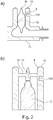
- FIG. 1a shows a schematic (not to scale) plan view of a portion of a single sensor.
- two flat electrical contacts 1 which are arranged side by side, that forms a gap 3 of about ⁇ 50 microns between the contacts 1.
- the gap 3 is covered in a transverse direction by a nanostructural expansion element 2 as a sensor element.
- a nanostructural expansion element 2 as a sensor element.
- two bond pads of the sensor wherein each contact surface 1, each with a bonding pad for connecting the sensor to a processing device is contacted.
- FIG. 1 b) shows an arrangement of a sensor on different examples of an inner wall with different geometries.
- the shape of the direct application surface of the inner wall on which the sensor is arranged plays a minor role, since only a sufficient deflection is required, which may be in the nano- to subnanometer range. To quantify the expected deflection, a variety of measurement techniques or even FEM simulations can be useful. Free-form surfaces as application surfaces are also possible.
- FIG. 1 b) shows a cross section through a planar inner wall 4 in a sensor area.
- the inner wall 3 is formed flat both on a wall area side 6 and on a fluid area side 7.
- an insulating layer 5 is applied.
- FIG. 1c) shows a cross section through a sensor portion of an inner wall 4.
- the inner wall 4 is flat, on a fluid area side 7, the inner wall 4 is concave.
- the sensor is arranged at a location of minimum wall thickness of the inner wall.
- FIG. 1 d) shows a cross section through a sensor portion of an inner wall 4, which is curved as a whole, so that their wall thickness is constant.
- FIG. 1 e shows a cross section through a sensor portion of an inner wall 4, wherein the wall portion side 6 has a complicated geometry and the application surface of the sensor is a free-form surface.
- the fluid area side 7 is concave in shape, and the sensor is advantageously arranged at a location of minimum wall thickness of the inner wall 4 for optimizing the sensor signal.
- a sensor application in a region of the inner wall 4 is possible, in which both the wall area side 6 and the fluid area side 7 have complicated geometries and free-form surfaces.
- FIG. 1 f) shows a cross section through a sensor portion of an inner wall 4, wherein the inner wall was thinned in the sensor area, for example by means of milling, drilling or a chemical process.
- a non-conductive inner wall can be dispensed with an insulating layer.
- the inner wall 4 on the fluid-carrying side 7 does not have any sensor-related material transitions, steps or gaps (such as weld seams or the like) even after embedding the sensor.
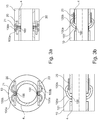
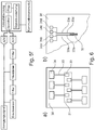
- FIG. 2 shows an inner wall 4 of a blood pump tube 10 with an axial flow blood pump 11 arranged therein.
- the inner wall 4 in the inlet region (optionally additionally in the region of the outlet cannula / diffuser) is located at a thinned position ) of the blood pump tube 10 one or more sensors 100 in a in Figures 1 c) - f ) applied configuration.
- the measured deflection indicates the ventricular pressure, when the normal pressure or, for example, the pressure within the hermetically sealed blood pump tube 10 is available as a reference.
- the pressure within the hermetically sealed blood pump tube 10 can be determined by means of a reference pressure sensor (eg, an absolute pressure sensor) arranged in the blood pump tube 10.
- a reference pressure sensor eg, an absolute pressure sensor
- one or more sensors 100 in an inlet and outlet area of a blood pump tube 10 are located in a blood pump tube 10 Figures 1 c) - f ) applied configuration.
- the instantaneous blood flow can be determined because the ventricular pressure (application 1.) is known.
- FIGS. 1 c) - f ) To detect a stop event in a cardiac assist system having a rotor 12 or a movable blood delivery / delivery element, one or more sensors 100 in the same as in FIGS Figures 1 c) - f ) and FIG. 2 a) and / or b) applied.
- the sensor 100 In FIG. 2 b) the sensor 100 is disposed near a bearing receptacle 13 for the rotor 12.
- FIGS. 1 c) - f the sensor 100 in FIG. 2 a) and / or b) applied.
- the sensor 100 In FIG. 2 b) the sensor 100 is disposed near a bearing receptacle 13 for the rotor 12.
- FIGS. 1 c) - f To detect a stop event in a cardiac assist system having a rotor 12 or a movable blood delivery / delivery element, one or more sensors 100 in the same as in FIGS Figures 1 c) - f )
- a plurality of sensors 100 may be distributed evenly over the entire inner wall 4 of the blood pump tube 10, in an inlet and / or outlet cannula (silicone cannula, plastic tube, metallic tube) and / or in a connector be embedded at the inlet / outlet (metal, plastic). From the deflection pulses occurring at the sensor surface (s) during the event, it is possible to conclude that an undesired impact situation exists and to initiate appropriate measures or signaling.
- a rotor 12 within a mechanically supported cardiac assist system generates an axial force received in a mechanical bearing 13 as blood is delivered as a function of the instantaneous backpressure becomes.
- one or more sensors 100 in the in FIG. 2 b) applied configuration shown.
- the bearing receptacle 13 located in the inlet is designed such that the received bearing force (axial force of the rotor 12) leads to a deflection which is measured either directly on a strut 14 or blood tube wall 4.
- the instantaneous blood flow can be determined because the ventricular pressure (application 1) is known.
- a rotor 12 within a mechanically supported cardiac assist system generates an axial force during delivery that is received in a mechanical bearing 13. If this rotor 12 is installed with a predetermined preload that is presumed to be known (usually required to avoid a gap between the bearing surfaces), a deflection in bearing 13 must be measured (application 4). If abrasion in the bearing 13 reduces the axial extent of the rotor 12, the deflection produced by the preload at the bearing point 13 also decreases as a result. The high-resolution measurement of the sensors 100 thus enables the wear on a bearing 13 to be detected and appropriate measures to be taken if there is a hazardous situation.
- the sensors detect 100 smallest deflections, they are also suitable for monitoring the running characteristics of a cardiac assistive system (measurement of periodic oscillations). Unwanted vibrations or sporadic impulses that occur, for example, when a patient falls, or due to a strong delay in, for example, an accident, can therefore be detected and processed accordingly.
- Implantable rotary blood pumps are i.d.R. from an inner pump tube as inner wall, the inner surface of which leads the blood. Outside the inner pump tube, nearly all blood pumps house the motor or other electronic or electro-mechanical assemblies, e.g. Sensors, active magnetic bearing components. Parts of these sensors can also be implemented as non-encapsulated sensors.
- an outer pump tube or a housing is also welded as an outer wall in almost all rotary blood pumps.
- Within the cavity (wall area) between the inner and outer pump tube or housing are the electrical connection elements.
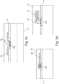
- FIGS. 3 a) - g connecting structures are shown, which make it possible to connect the sensors 100 electrically. It should also be possible to connect more than one sensor 100 at a time. The number is usefully between one and four sensors. In addition, the electrical connection and a signal pre-processing device is shown.
- FIG. 3 a) 1 shows a cross section on the left and on the right a longitudinal section through a pump tube 10.
- a printed circuit board (PCB) or MID accommodates the two bonding wires 100a and 100b, each of a sensor 100 placed on the inner tube 4 of the pump tube 10.
- the bonding wires 100 a, 100 b are applied as a ball by means of wire bonding and are rewired on the printed circuit board 20.
- the (flexible) circuit board 20 is located directly above the sensor 100 and has a hole or lead-through 21 for the bonding wires 100a, 100b.
- FIG. 3 b shows a printed circuit board (PCB) or MID 20 next to the sensor 100.
- the bonding wires are attached to the sensor 100 as ball 101 (left) or wedge 102 (right) and rewired on the board.
- passive or active electrical components 22 may already be accommodated on the printed circuit board 20 as a preprocessing device in order to carry out a first filtering or preprocessing.
- FIG. 3 c shows a 3D-MID circuit board 20 as a connector board. This requires no bonding wires for connection and can be soldered or plugged directly onto the sensor 100.
- electrical components 22 may already be provided as a preprocessing device here.
- FIG. 3 d shows a complete sensor assembly 100, which is electrically connected to either a plugged and soldered board 20 or individually insulated wires 23.
- the insulation 24 can be made, for example, via a Teflon sheath, which has an extremely high dielectric strength at a very small thickness.
- FIG. 3 e the electrical connection of a rewiring board 20 at the sensor 100 to a motherboard or other pump electronics 200 in the pump tube 10 is shown.
- This connection is made by infected or soldered galvanic conductor 201 and transmits the sensor data to the pump electronics 200 for further processing.
- the forwarding can also be carried out via 3D-shaped circuit boards (eg MID circuit boards).
- Another way to transfer the data within the pump tube 10 is a wireless communication interface.
- the pump tube 10 has a bearing stator 13, which is in the flow.
- a sensor 100 in this bearing stator 13 is electrically connected via a channel 16 within the stator structure 17.
- lines 100a, 100b are laid through the channel 16 from the sensor 100 to the evaluation or processing electronics 21.
- the channel 16 is in the simplest case a bore through the stator blades 17, which are connected to the pump tube 10.
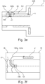
- FIG. 3 g can be mounted within the pump tube 10 in addition to the actual pressure-sensitive sensor 100 nor a reference pressure sensor 103.
- This sensor 103 is in the simplest case an IC on an electronic board 22 within the pump housing. By means of this pressure sensor 103, fluctuations in the reference pressure in the hermetically sealed pump housing can be detected. The pressure fluctuations can be used to compensate for measurement errors of the actual sensor 100.
- FIG. 4 shows a simplified representation of the connection of the sensors 100 to a processing device.
- the signals of individual sensors 100 on a pump electronics 300 can be combined and processed via the electrical connections 100a, 100b, 201.
- the rewiring boards 300 may be purely passive or already contain preprocessing.
- the signal from the pressure sensor can be amplified and filtered for signal recording.
- the filters may be mounted in front of and / or behind the amplifier, respectively. Also, the amplifier may be designed as an active filter element.
- the amplified signal can be digitized by an analog-to-digital converter (ADC). After digitization, the waveform can be saved and further filtered as needed. Digital filtering takes up no space in the pump compared to discrete filtering.
- the filters are intended to remove interference from the useful signal. Faults may have their source outside the pump such as EMC or shock. A fault that originates from the pump itself is, for example, the stray magnetic field of the magnet in the pump rotor. Disturbances such as EMC can be filtered via a frequency selection.
- the interference can be filtered out via a correlation filter become.
- the correlation filter can be executed in the flow control or as an active filter element.
- the interference can also be recorded via a dummy pressure sensor.
- the dummy pressure sensor should have the same structure as the pressure sensor, with the difference that it has a different pressure dependence than the pressure sensor. Sensitivity to disturbances should be comparable. By comparing the dummy pressure sensor signal and the pressure sensor signal, the interference can be canceled. The situation is similar with the disturbances caused by the stray field of the pump rotor magnet. Since the position and speed of the rotor magnet is known to the motor driver, this signal can also be deducted.
- FIG. 6 a) shows a plan view of a sensor region 30 with six sensor structures 32, 33, 34th
- FIG. 6 b) shows a schematic representation of a sensor structure 32, 33, 34 consisting of four interconnected to a full bridge sensors.
- the sensors of the sensor structures 32, 33, 34 are arranged in a region 31 of maximum deformation within the sensor region 30.
- four sensors are interconnected to form a full-bridge circuit 32 (measuring bridge) for temperature compensation of the sensors.
- Each full bridge 32 has four bond pads for electrical connection to a processing device.
Priority Applications (5)
| Application Number | Priority Date | Filing Date | Title |
|---|---|---|---|
| EP18174341.0A EP3572104A1 (fr) | 2018-05-25 | 2018-05-25 | Composant de guidage d'un fluide au moyen d'un capteur |
| PCT/EP2019/063685 WO2019224401A1 (fr) | 2018-05-25 | 2019-05-27 | Module destiné à conduire un fluide pourvu d'un capteur |
| CN201980047844.2A CN112423833A (zh) | 2018-05-25 | 2019-05-27 | 具有传感器的用于引导流体的部件 |
| DE112019002663.1T DE112019002663A5 (de) | 2018-05-25 | 2019-05-27 | Bauteil zum Führen eines Fluids mit einem Sensor |
| US17/057,049 US20210361931A1 (en) | 2018-05-25 | 2019-05-27 | Component for conducting a fluid having a sensor |
Applications Claiming Priority (1)
| Application Number | Priority Date | Filing Date | Title |
|---|---|---|---|
| EP18174341.0A EP3572104A1 (fr) | 2018-05-25 | 2018-05-25 | Composant de guidage d'un fluide au moyen d'un capteur |
Publications (1)
| Publication Number | Publication Date |
|---|---|
| EP3572104A1 true EP3572104A1 (fr) | 2019-11-27 |
Family
ID=62630898
Family Applications (1)
| Application Number | Title | Priority Date | Filing Date |
|---|---|---|---|
| EP18174341.0A Withdrawn EP3572104A1 (fr) | 2018-05-25 | 2018-05-25 | Composant de guidage d'un fluide au moyen d'un capteur |
Country Status (5)
| Country | Link |
|---|---|
| US (1) | US20210361931A1 (fr) |
| EP (1) | EP3572104A1 (fr) |
| CN (1) | CN112423833A (fr) |
| DE (1) | DE112019002663A5 (fr) |
| WO (1) | WO2019224401A1 (fr) |
Families Citing this family (1)
| Publication number | Priority date | Publication date | Assignee | Title |
|---|---|---|---|---|
| CN113476739B (zh) * | 2021-06-07 | 2022-11-08 | 浙江迪远医疗器械有限公司 | 具有检测装置的血液泵 |
Citations (5)
| Publication number | Priority date | Publication date | Assignee | Title |
|---|---|---|---|---|
| US6367333B1 (en) * | 1999-05-04 | 2002-04-09 | Apex Medical, Inc. | Notch diaphragm pressure sensor |
| US20170112988A1 (en) * | 2012-11-30 | 2017-04-27 | The Penn State Research Foundation | Smart Tip LVAD Inlet Cannula |
| EP3222206A1 (fr) * | 2016-03-23 | 2017-09-27 | ETH Zurich | Procédé pour la fabrication d'un dispositif de transport, dispositif de transport, système de détection d'un paramètre physique et procédé de détection d'un paramètre physique |
| US20170348470A1 (en) * | 2016-06-06 | 2017-12-07 | Abiomed, Inc. | Blood pump assembly having a sensor and a sensor shield |
| US20180085505A1 (en) * | 2016-09-23 | 2018-03-29 | Heartware, Inc. | Blood pump with sensors on housing surface |
Family Cites Families (5)
| Publication number | Priority date | Publication date | Assignee | Title |
|---|---|---|---|---|
| KR20160086320A (ko) * | 2013-08-27 | 2016-07-19 | 퀀텀 바이오시스템즈 가부시키가이샤 | 나노-갭 전극 및 이를 제조하기 위한 방법들 |
| DE102013114407A1 (de) * | 2013-12-18 | 2015-06-18 | Endress + Hauser Gmbh + Co. Kg | Drucksensor |
| US20160000547A1 (en) * | 2014-07-03 | 2016-01-07 | Elwha Llc | Devices, methods, and systems related to expandable implants |
| DE102015216626A1 (de) * | 2015-08-31 | 2017-03-02 | Siemens Aktiengesellschaft | Drucksensoranordnung sowie Messumformer zur Prozessinstrumentierung mit einer derartigen Drucksensoranordnung |
| JP2018040776A (ja) * | 2016-09-09 | 2018-03-15 | 株式会社NejiLaw | センサ構造、センサ構造付部材 |
-
2018
- 2018-05-25 EP EP18174341.0A patent/EP3572104A1/fr not_active Withdrawn
-
2019
- 2019-05-27 DE DE112019002663.1T patent/DE112019002663A5/de active Pending
- 2019-05-27 WO PCT/EP2019/063685 patent/WO2019224401A1/fr active Application Filing
- 2019-05-27 CN CN201980047844.2A patent/CN112423833A/zh active Pending
- 2019-05-27 US US17/057,049 patent/US20210361931A1/en active Pending
Patent Citations (5)
| Publication number | Priority date | Publication date | Assignee | Title |
|---|---|---|---|---|
| US6367333B1 (en) * | 1999-05-04 | 2002-04-09 | Apex Medical, Inc. | Notch diaphragm pressure sensor |
| US20170112988A1 (en) * | 2012-11-30 | 2017-04-27 | The Penn State Research Foundation | Smart Tip LVAD Inlet Cannula |
| EP3222206A1 (fr) * | 2016-03-23 | 2017-09-27 | ETH Zurich | Procédé pour la fabrication d'un dispositif de transport, dispositif de transport, système de détection d'un paramètre physique et procédé de détection d'un paramètre physique |
| US20170348470A1 (en) * | 2016-06-06 | 2017-12-07 | Abiomed, Inc. | Blood pump assembly having a sensor and a sensor shield |
| US20180085505A1 (en) * | 2016-09-23 | 2018-03-29 | Heartware, Inc. | Blood pump with sensors on housing surface |
Also Published As
| Publication number | Publication date |
|---|---|
| DE112019002663A5 (de) | 2021-03-11 |
| US20210361931A1 (en) | 2021-11-25 |
| WO2019224401A1 (fr) | 2019-11-28 |
| CN112423833A (zh) | 2021-02-26 |
Similar Documents
| Publication | Publication Date | Title |
|---|---|---|
| EP2038627B1 (fr) | Detecteur de force et procede servant a detecter au moins une composante de force | |
| EP2726833A1 (fr) | Procédé de fonctionnement d'un capteur absolu ou relatif comportant un convertisseur capacitif | |
| DE10160794B4 (de) | Signalverarbeitungseinrichtung für einen Druckschalter od. dgl. | |
| DE10017572A1 (de) | Wälzlager mit fernabfragbaren Erfassungseinheiten | |
| DE102011083487A1 (de) | Beschleunigungssensor und Verfahren zum Betrieb eines Beschleunigungssensors | |
| EP1382952B1 (fr) | Capteur de pression micromécanique avec le transducteur sur le diaphragme de séparation de la boîte | |
| DE102017104547A1 (de) | Drucksensor sowie Druckmessverfahren | |
| DE3447396A1 (de) | Elektrischer druckgeber | |
| DE102010041170A1 (de) | Ventilbaugruppe mit Rückschlagventil und Druckaufnehmer für ein Kraftfahrzeug | |
| DE112014001242T5 (de) | Sensor und Verfahren zur Herstellung eines Sensors | |
| EP2954867A1 (fr) | Carte logique montée à plat pour cathéter d'ablation ayant une fonctionnalité de mesure de force | |
| EP2823274A1 (fr) | Élément de mesure micromécanique | |
| EP3572104A1 (fr) | Composant de guidage d'un fluide au moyen d'un capteur | |
| DE102011002884A1 (de) | Elektronische Kraft- und/oder Druck- und/oder Temperaturmessschaltung | |
| WO2010066296A1 (fr) | Corps soumis à la déformation pour détecteur de couple | |
| EP3384263A1 (fr) | Ensemble capteur de pression et transducteur de mesure pour l'instrumentation de traitement comportant un tel ensemble capteur de pression | |
| DE102007026827A1 (de) | Aufnehmer zur Messung mechanischer Kräfte und Momente | |
| EP3237866B1 (fr) | Convertisseur de pression et procédé permettant de faire fonctionner ledit convertisseur | |
| EP2554964B1 (fr) | Dispositif de mesure de la pression et de la température | |
| WO2011160794A1 (fr) | Capteur de force piézo-résistif | |
| DE102011017462A1 (de) | Vorrichtung zum Messen einer Druckdifferenz, insbesondere kapazitiver Differenzdrucksensor | |
| WO2014090228A1 (fr) | Dispositif de test fiche mâle-fiche femelle | |
| DE102006058269B4 (de) | Verfahren zur Kalibrierung mindestens eines Drucksensors und entsprechender Drucksensor | |
| DE102005038822A1 (de) | Integrierter Drucksensor mit kapazitivem Messprinzip | |
| EP2368837B1 (fr) | Capteur sur circuit imprimé et son procédé de fabrication |
Legal Events
| Date | Code | Title | Description |
|---|---|---|---|
| PUAI | Public reference made under article 153(3) epc to a published international application that has entered the european phase |
Free format text: ORIGINAL CODE: 0009012 |
|
| AK | Designated contracting states |
Kind code of ref document: A1 Designated state(s): AL AT BE BG CH CY CZ DE DK EE ES FI FR GB GR HR HU IE IS IT LI LT LU LV MC MK MT NL NO PL PT RO RS SE SI SK SM TR |
|
| AX | Request for extension of the european patent |
Extension state: BA ME |
|
| STAA | Information on the status of an ep patent application or granted ep patent |
Free format text: STATUS: THE APPLICATION IS DEEMED TO BE WITHDRAWN |
|
| 18D | Application deemed to be withdrawn |
Effective date: 20200603 |