EP3572104A1 - Component for conveying a fluid with a sensor - Google Patents
Component for conveying a fluid with a sensor Download PDFInfo
- Publication number
- EP3572104A1 EP3572104A1 EP18174341.0A EP18174341A EP3572104A1 EP 3572104 A1 EP3572104 A1 EP 3572104A1 EP 18174341 A EP18174341 A EP 18174341A EP 3572104 A1 EP3572104 A1 EP 3572104A1
- Authority
- EP
- European Patent Office
- Prior art keywords
- wall
- sensor
- sensor element
- component
- region
- Prior art date
- Legal status (The legal status is an assumption and is not a legal conclusion. Google has not performed a legal analysis and makes no representation as to the accuracy of the status listed.)
- Withdrawn
Links
Images


Classifications
-
- A—HUMAN NECESSITIES
- A61—MEDICAL OR VETERINARY SCIENCE; HYGIENE
- A61M—DEVICES FOR INTRODUCING MEDIA INTO, OR ONTO, THE BODY; DEVICES FOR TRANSDUCING BODY MEDIA OR FOR TAKING MEDIA FROM THE BODY; DEVICES FOR PRODUCING OR ENDING SLEEP OR STUPOR
- A61M60/00—Blood pumps; Devices for mechanical circulatory actuation; Balloon pumps for circulatory assistance
- A61M60/40—Details relating to driving
- A61M60/403—Details relating to driving for non-positive displacement blood pumps
-
- A—HUMAN NECESSITIES
- A61—MEDICAL OR VETERINARY SCIENCE; HYGIENE
- A61M—DEVICES FOR INTRODUCING MEDIA INTO, OR ONTO, THE BODY; DEVICES FOR TRANSDUCING BODY MEDIA OR FOR TAKING MEDIA FROM THE BODY; DEVICES FOR PRODUCING OR ENDING SLEEP OR STUPOR
- A61M60/00—Blood pumps; Devices for mechanical circulatory actuation; Balloon pumps for circulatory assistance
- A61M60/80—Constructional details other than related to driving
- A61M60/855—Constructional details other than related to driving of implantable pumps or pumping devices
- A61M60/857—Implantable blood tubes
-
- A—HUMAN NECESSITIES
- A61—MEDICAL OR VETERINARY SCIENCE; HYGIENE
- A61M—DEVICES FOR INTRODUCING MEDIA INTO, OR ONTO, THE BODY; DEVICES FOR TRANSDUCING BODY MEDIA OR FOR TAKING MEDIA FROM THE BODY; DEVICES FOR PRODUCING OR ENDING SLEEP OR STUPOR
- A61M60/00—Blood pumps; Devices for mechanical circulatory actuation; Balloon pumps for circulatory assistance
- A61M60/10—Location thereof with respect to the patient's body
- A61M60/122—Implantable pumps or pumping devices, i.e. the blood being pumped inside the patient's body
- A61M60/126—Implantable pumps or pumping devices, i.e. the blood being pumped inside the patient's body implantable via, into, inside, in line, branching on, or around a blood vessel
- A61M60/148—Implantable pumps or pumping devices, i.e. the blood being pumped inside the patient's body implantable via, into, inside, in line, branching on, or around a blood vessel in line with a blood vessel using resection or like techniques, e.g. permanent endovascular heart assist devices
-
- A—HUMAN NECESSITIES
- A61—MEDICAL OR VETERINARY SCIENCE; HYGIENE
- A61M—DEVICES FOR INTRODUCING MEDIA INTO, OR ONTO, THE BODY; DEVICES FOR TRANSDUCING BODY MEDIA OR FOR TAKING MEDIA FROM THE BODY; DEVICES FOR PRODUCING OR ENDING SLEEP OR STUPOR
- A61M60/00—Blood pumps; Devices for mechanical circulatory actuation; Balloon pumps for circulatory assistance
- A61M60/10—Location thereof with respect to the patient's body
- A61M60/122—Implantable pumps or pumping devices, i.e. the blood being pumped inside the patient's body
- A61M60/165—Implantable pumps or pumping devices, i.e. the blood being pumped inside the patient's body implantable in, on, or around the heart
- A61M60/178—Implantable pumps or pumping devices, i.e. the blood being pumped inside the patient's body implantable in, on, or around the heart drawing blood from a ventricle and returning the blood to the arterial system via a cannula external to the ventricle, e.g. left or right ventricular assist devices
-
- A—HUMAN NECESSITIES
- A61—MEDICAL OR VETERINARY SCIENCE; HYGIENE
- A61M—DEVICES FOR INTRODUCING MEDIA INTO, OR ONTO, THE BODY; DEVICES FOR TRANSDUCING BODY MEDIA OR FOR TAKING MEDIA FROM THE BODY; DEVICES FOR PRODUCING OR ENDING SLEEP OR STUPOR
- A61M60/00—Blood pumps; Devices for mechanical circulatory actuation; Balloon pumps for circulatory assistance
- A61M60/20—Type thereof
- A61M60/205—Non-positive displacement blood pumps
- A61M60/216—Non-positive displacement blood pumps including a rotating member acting on the blood, e.g. impeller
- A61M60/237—Non-positive displacement blood pumps including a rotating member acting on the blood, e.g. impeller the blood flow through the rotating member having mainly axial components, e.g. axial flow pumps
-
- A—HUMAN NECESSITIES
- A61—MEDICAL OR VETERINARY SCIENCE; HYGIENE
- A61M—DEVICES FOR INTRODUCING MEDIA INTO, OR ONTO, THE BODY; DEVICES FOR TRANSDUCING BODY MEDIA OR FOR TAKING MEDIA FROM THE BODY; DEVICES FOR PRODUCING OR ENDING SLEEP OR STUPOR
- A61M60/00—Blood pumps; Devices for mechanical circulatory actuation; Balloon pumps for circulatory assistance
- A61M60/50—Details relating to control
- A61M60/508—Electronic control means, e.g. for feedback regulation
- A61M60/515—Regulation using real-time patient data
- A61M60/523—Regulation using real-time patient data using blood flow data, e.g. from blood flow transducers
-
- A—HUMAN NECESSITIES
- A61—MEDICAL OR VETERINARY SCIENCE; HYGIENE
- A61M—DEVICES FOR INTRODUCING MEDIA INTO, OR ONTO, THE BODY; DEVICES FOR TRANSDUCING BODY MEDIA OR FOR TAKING MEDIA FROM THE BODY; DEVICES FOR PRODUCING OR ENDING SLEEP OR STUPOR
- A61M60/00—Blood pumps; Devices for mechanical circulatory actuation; Balloon pumps for circulatory assistance
- A61M60/50—Details relating to control
- A61M60/508—Electronic control means, e.g. for feedback regulation
- A61M60/515—Regulation using real-time patient data
- A61M60/531—Regulation using real-time patient data using blood pressure data, e.g. from blood pressure sensors
-
- A—HUMAN NECESSITIES
- A61—MEDICAL OR VETERINARY SCIENCE; HYGIENE
- A61M—DEVICES FOR INTRODUCING MEDIA INTO, OR ONTO, THE BODY; DEVICES FOR TRANSDUCING BODY MEDIA OR FOR TAKING MEDIA FROM THE BODY; DEVICES FOR PRODUCING OR ENDING SLEEP OR STUPOR
- A61M60/00—Blood pumps; Devices for mechanical circulatory actuation; Balloon pumps for circulatory assistance
- A61M60/50—Details relating to control
- A61M60/508—Electronic control means, e.g. for feedback regulation
- A61M60/538—Regulation using real-time blood pump operational parameter data, e.g. motor current
- A61M60/546—Regulation using real-time blood pump operational parameter data, e.g. motor current of blood flow, e.g. by adapting rotor speed
-
- A—HUMAN NECESSITIES
- A61—MEDICAL OR VETERINARY SCIENCE; HYGIENE
- A61M—DEVICES FOR INTRODUCING MEDIA INTO, OR ONTO, THE BODY; DEVICES FOR TRANSDUCING BODY MEDIA OR FOR TAKING MEDIA FROM THE BODY; DEVICES FOR PRODUCING OR ENDING SLEEP OR STUPOR
- A61M60/00—Blood pumps; Devices for mechanical circulatory actuation; Balloon pumps for circulatory assistance
- A61M60/50—Details relating to control
- A61M60/508—Electronic control means, e.g. for feedback regulation
- A61M60/538—Regulation using real-time blood pump operational parameter data, e.g. motor current
- A61M60/554—Regulation using real-time blood pump operational parameter data, e.g. motor current of blood pressure
-
- A—HUMAN NECESSITIES
- A61—MEDICAL OR VETERINARY SCIENCE; HYGIENE
- A61M—DEVICES FOR INTRODUCING MEDIA INTO, OR ONTO, THE BODY; DEVICES FOR TRANSDUCING BODY MEDIA OR FOR TAKING MEDIA FROM THE BODY; DEVICES FOR PRODUCING OR ENDING SLEEP OR STUPOR
- A61M60/00—Blood pumps; Devices for mechanical circulatory actuation; Balloon pumps for circulatory assistance
- A61M60/80—Constructional details other than related to driving
- A61M60/802—Constructional details other than related to driving of non-positive displacement blood pumps
- A61M60/81—Pump housings
- A61M60/816—Sensors arranged on or in the housing, e.g. ultrasound flow sensors
-
- A—HUMAN NECESSITIES
- A61—MEDICAL OR VETERINARY SCIENCE; HYGIENE
- A61M—DEVICES FOR INTRODUCING MEDIA INTO, OR ONTO, THE BODY; DEVICES FOR TRANSDUCING BODY MEDIA OR FOR TAKING MEDIA FROM THE BODY; DEVICES FOR PRODUCING OR ENDING SLEEP OR STUPOR
- A61M60/00—Blood pumps; Devices for mechanical circulatory actuation; Balloon pumps for circulatory assistance
- A61M60/80—Constructional details other than related to driving
- A61M60/802—Constructional details other than related to driving of non-positive displacement blood pumps
- A61M60/818—Bearings
- A61M60/825—Contact bearings, e.g. ball-and-cup or pivot bearings
-
- G—PHYSICS
- G01—MEASURING; TESTING
- G01L—MEASURING FORCE, STRESS, TORQUE, WORK, MECHANICAL POWER, MECHANICAL EFFICIENCY, OR FLUID PRESSURE
- G01L9/00—Measuring steady of quasi-steady pressure of fluid or fluent solid material by electric or magnetic pressure-sensitive elements; Transmitting or indicating the displacement of mechanical pressure-sensitive elements, used to measure the steady or quasi-steady pressure of a fluid or fluent solid material, by electric or magnetic means
- G01L9/0026—Transmitting or indicating the displacement of flexible, deformable tubes by electric, electromechanical, magnetic or electromagnetic means
- G01L9/0027—Transmitting or indicating the displacement of flexible, deformable tubes by electric, electromechanical, magnetic or electromagnetic means using variations in ohmic resistance
-
- A—HUMAN NECESSITIES
- A61—MEDICAL OR VETERINARY SCIENCE; HYGIENE
- A61M—DEVICES FOR INTRODUCING MEDIA INTO, OR ONTO, THE BODY; DEVICES FOR TRANSDUCING BODY MEDIA OR FOR TAKING MEDIA FROM THE BODY; DEVICES FOR PRODUCING OR ENDING SLEEP OR STUPOR
- A61M2205/00—General characteristics of the apparatus
- A61M2205/33—Controlling, regulating or measuring
- A61M2205/3327—Measuring
-
- A—HUMAN NECESSITIES
- A61—MEDICAL OR VETERINARY SCIENCE; HYGIENE
- A61M—DEVICES FOR INTRODUCING MEDIA INTO, OR ONTO, THE BODY; DEVICES FOR TRANSDUCING BODY MEDIA OR FOR TAKING MEDIA FROM THE BODY; DEVICES FOR PRODUCING OR ENDING SLEEP OR STUPOR
- A61M2207/00—Methods of manufacture, assembly or production
Definitions
- the present invention relates to a component for guiding a fluid with a sensor for measuring a deformation of the component. Furthermore, the invention relates to a method for producing the component containing the sensor.
- the relevant component can be used in particular in the field of cardiac support systems.
- the geometric nature of the blood-conducting route for the applicability of the respective measuring apparatus must be adjusted accordingly (eg flattening of the inner wall, large thinning a tube wall or Tangentialhunt, bulging a blood-carrying wall to create space).
- any sensors in the inlet area or outlet area of a blood pump must be electrically connected to the overall system. This includes the electrical contacting of individual physical sensors or the connection of entire assemblies. Due to the limited space between the inner wall and the outer wall of the blood pump, the sensor elements and also the wiring must have a low height.
- the object of the present invention is to provide a component for guiding a fluid with a sensor, for example for a cardiac assist system, which solves the problems described above and wherein the sensor is integrated into the component such that important states of a connectable to the component Fluid system, such as a cardiac assist system as well as a patient interacting with the cardiac assist system, can be detected, the dimensions of the component can not be increased, the sensor does not affect the fluid or the fluid flow and does not come into contact with an installation environment of the component.
- a sensor for example for a cardiac assist system
- the component according to the invention for guiding a fluid with a sensor comprises an inner and an outer wall, wherein the inner wall is designed to guide the fluid, the outer wall terminates the component to the outside and a wall region is formed between the inner and the outer wall.
- the component according to the invention is characterized in that the sensor has an electromechanical sensor element and is arranged in the wall region on the inner wall, wherein the sensor is arranged to measure a degree of deformation of the inner wall in the region of the sensor by means of the sensor element and as electrical Output signal, wherein the electromechanical sensor element has a length and / or a width of ⁇ 50 microns.
- a sensor is understood here as a layer structure which preferably has two electrical contacts in a first layer, which are separated from one another by a gap.
- the sensor element can then be arranged in a second layer on the electrical contacts.
- the sensor element is an electromechanical element, preferably a nanostructural expansion element, and does not itself comprise any other components, e.g. electrical conductor, up.
- the sensor element preferably extends across the gap in a transverse direction.
- the sensor element can protrude into the first layer in the region of the gap.
- the sensor preferably comprises two bond pads, wherein in each case a bonding pad is electrically contacted with one of the electrical contacts.
- the inner wall has no sensor-related material transitions, steps or gaps (such as welds or the like) on the fluid-leading side even after embedding of the sensor.
- the invention described herein is applicable to all implantable and hemocompatible materials, and is capable of measuring minute deflections (strokes, vibrations, pulses) without invasive effects on a blood-carrying element that can not be detected with conventional sensors (eg strain gauges, ultrasonic sensors , optical sensors), and to output this information. To the same extent it behaves with the required space, since the applied sensor itself takes only a few cubic microns, thus very easy to integrate, and can be applied in part in previously inaccessible structures.
- sensors eg strain gauges, ultrasonic sensors , optical sensors
- the sensor element may be a nanostructural expansion element, which is cohesively applied to the contacts, so that the contacts are electrically contacted to each other via the sensor element, wherein the electrical contacts are applied to the inner wall, that the sensor element at Deformation of the inner wall in the region of the sensor deformed with the inner wall, so that between the electrical contacts, the electrical signal is measurable.
- a plurality of sensors can be arranged in the wall region on the inner wall.
- four sensors can be arranged on the inner wall, which are preferably interconnected to form a full or half-bridge circuit, in order to reduce a temperature dependence of the sensors.
- an electrical insulation layer may be arranged, which is materially connected to the inner wall and the electrical contacts.
- the sensor element may in particular comprise a nanocrystalline composite material (nanocomposite), which can preferably be imprinted by means of nano-3D printing and whose composition can be changed as desired.
- the sensor element may comprise a metal and / or a semiconductor material.
- the sensor element can also have a metal doped with charge carriers and / or a semiconductor material doped with charge carriers in order to to set an electrical conductivity and / or an electrical resistance of the sensor element.
- the electrical signal may in particular include a change in an electrical resistance of the sensor.
- the sensor element has a length and / or a width of ⁇ 15 ⁇ m, in particular ⁇ 10 ⁇ m, in particular ⁇ 3 ⁇ m and / or a thickness of ⁇ 50 ⁇ m, in particular ⁇ 15 ⁇ m, in particular ⁇ 10 ⁇ m, in particular ⁇ 3 ⁇ m having.
- the electrical contacts may be applied to the inner wall such that a gap of ⁇ 50 ⁇ m, in particular ⁇ 30 ⁇ m, in particular ⁇ 15 ⁇ m, in particular ⁇ 10 ⁇ m, in particular ⁇ 3 ⁇ m, exists between the contacts, the gap being in a transverse direction completely covered by the sensor element.
- the senor is arranged in a thinned region of the inner wall.
- a wall thickness in the thinned region is preferably ⁇ 5 ⁇ m, in particular ⁇ 100 ⁇ m and / or ⁇ 500 ⁇ m, in particular ⁇ 200 ⁇ m.
- the component can be a blood pump, wherein one or more sensors in the inlet area and / or outlet area are arranged in the wall area on the inner wall of the blood pump, and from the deformation of the inner wall a blood pressure in the inlet area and / or outlet area, an instantaneous flow rate and / or running properties of the blood pump can be determined.
- the component may further be a blood pump with a movable conveying element, wherein one or more sensors are arranged on the inner wall in the wall region of the blood pump, and from the deformation of the inner wall, a stop of the conveying element on the inner wall can be fixed.
- the component may further be a mechanically mounted rotary blood pump, wherein one or more sensors are arranged in the region of the bearing receptacle in the wall region on the inner wall, and from the deformation the inner wall, a bearing force and / or a bearing wear can be determined.
- a plurality of sensors can be arranged along a circumference of the inner wall in the wall region or in the region of the inner wall of similar static pressure conditions. With the help of the large number of sensors, averages of the measured values can be formed, thus making measurements of the sensors more accurate.
- electrical connection elements can be arranged in the wall region, via which the sensor is connected to a processing device.
- the connecting elements may comprise a printed circuit board, wherein one or more sensors are connected directly to the printed circuit board via the electrical contacts or via bonding wires, or individually insulated wires, in particular Teflon-insulated wires.
- electrical components for preprocessing the electrical signals in particular for preamplification, can be arranged on the printed circuit board.
- the present invention also includes a method for manufacturing a component for guiding a fluid with a sensor.
- the method according to the invention comprises the following steps: forming an inner and an outer wall of the component, wherein the inner wall is designed to guide the fluid and the outer wall is designed to close the component to the outside, and the inner and the outer wall can be joined together in that a wall region results between the inner and the outer wall, arranging a sensor with an electromechanical sensor element in the wall region on the inner wall, wherein the sensor is arranged, by means of the sensor element to a degree of deformation of the inner wall in the region of the sensor measure and output as an electrical signal, wherein the electromechanical sensor element has a length and / or a width of ⁇ 50 microns, and joining the inner and outer wall.
- an insulating layer can be applied to the inner wall in the wall region before arranging the sensor. This is particularly necessary if the inner wall has an electrically conductive material to prevent a short circuit between the contacts.
- the arrangement of the sensor may in particular comprise the following steps: application of electrical contacts on the inner wall or on the insulation layer for removing the electrical signal and application of an electromechanical sensor element on the electrical contacts.
- the method may include that prior to arranging the sensor on the inner wall or before applying the insulation layer, a wall thickness of the wall in the region of the sensor is thinned, in particular to a wall thickness of ⁇ 5 ⁇ m, in particular ⁇ 100 ⁇ m and / or ⁇ 500 microns, in particular ⁇ 200 microns is thinned.
- the method can include that the sensor element is applied to the insulation layer by means of nano-3D printing, sputtering or by means of an etching process.
- the method may include that a sensitivity of the sensor element is adjusted by introducing a higher or lower number of charge carriers into the sensor element.
- the following embodiments relate primarily to the field of blood-carrying components, such as e.g. the blood pumps for cardiac support systems.
- the invention is not limited to this field, but is applicable to fluid-conducting components of any kind.
- An object of the present invention with respect to blood-bearing components is to measure minute deflections (strokes, vibrations, pulses) without invasive effects on a blood-conducting element, and to output this information.
- minute deflections strokes, vibrations, pulses
- specific measurement configurations can be provided, which enable the measurement of signals without negative influence on fluidic as well as hemocompatible performance of a blood-carrying and or blood-promoting system.
- nano- or microstructures in a corresponding distance and course to a haemocompatible, or coated material (component) can be applied. Since these nanostructures serve as interconnects, they consist of a conductive material which can be applied with the aid of microsytemtechnical manufacturing processes (eg lithographic, microetching, PEVDM, etc.). Another prerequisite is the electronically passive application surface on which the sensor element is applied, which in the case of a conductive inner wall additionally requires an insulation layer.
- a nanostructural expansion element is then applied, which leads to a change in conductivity in the expansion element at the smallest deflections due to the resulting change in length of the expansion element, and thus makes a voltage delta between the interconnects measurable.
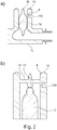
- FIG. 1a shows a schematic (not to scale) plan view of a portion of a single sensor.
- two flat electrical contacts 1 which are arranged side by side, that forms a gap 3 of about ⁇ 50 microns between the contacts 1.
- the gap 3 is covered in a transverse direction by a nanostructural expansion element 2 as a sensor element.
- a nanostructural expansion element 2 as a sensor element.
- two bond pads of the sensor wherein each contact surface 1, each with a bonding pad for connecting the sensor to a processing device is contacted.
- FIG. 1 b) shows an arrangement of a sensor on different examples of an inner wall with different geometries.
- the shape of the direct application surface of the inner wall on which the sensor is arranged plays a minor role, since only a sufficient deflection is required, which may be in the nano- to subnanometer range. To quantify the expected deflection, a variety of measurement techniques or even FEM simulations can be useful. Free-form surfaces as application surfaces are also possible.
- FIG. 1 b) shows a cross section through a planar inner wall 4 in a sensor area.
- the inner wall 3 is formed flat both on a wall area side 6 and on a fluid area side 7.
- an insulating layer 5 is applied.
- FIG. 1c) shows a cross section through a sensor portion of an inner wall 4.
- the inner wall 4 is flat, on a fluid area side 7, the inner wall 4 is concave.
- the sensor is arranged at a location of minimum wall thickness of the inner wall.
- FIG. 1 d) shows a cross section through a sensor portion of an inner wall 4, which is curved as a whole, so that their wall thickness is constant.
- FIG. 1 e shows a cross section through a sensor portion of an inner wall 4, wherein the wall portion side 6 has a complicated geometry and the application surface of the sensor is a free-form surface.
- the fluid area side 7 is concave in shape, and the sensor is advantageously arranged at a location of minimum wall thickness of the inner wall 4 for optimizing the sensor signal.
- a sensor application in a region of the inner wall 4 is possible, in which both the wall area side 6 and the fluid area side 7 have complicated geometries and free-form surfaces.
- FIG. 1 f) shows a cross section through a sensor portion of an inner wall 4, wherein the inner wall was thinned in the sensor area, for example by means of milling, drilling or a chemical process.
- a non-conductive inner wall can be dispensed with an insulating layer.
- the inner wall 4 on the fluid-carrying side 7 does not have any sensor-related material transitions, steps or gaps (such as weld seams or the like) even after embedding the sensor.
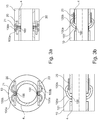
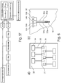
- FIG. 2 shows an inner wall 4 of a blood pump tube 10 with an axial flow blood pump 11 arranged therein.
- the inner wall 4 in the inlet region (optionally additionally in the region of the outlet cannula / diffuser) is located at a thinned position ) of the blood pump tube 10 one or more sensors 100 in a in Figures 1 c) - f ) applied configuration.
- the measured deflection indicates the ventricular pressure, when the normal pressure or, for example, the pressure within the hermetically sealed blood pump tube 10 is available as a reference.
- the pressure within the hermetically sealed blood pump tube 10 can be determined by means of a reference pressure sensor (eg, an absolute pressure sensor) arranged in the blood pump tube 10.
- a reference pressure sensor eg, an absolute pressure sensor
- one or more sensors 100 in an inlet and outlet area of a blood pump tube 10 are located in a blood pump tube 10 Figures 1 c) - f ) applied configuration.
- the instantaneous blood flow can be determined because the ventricular pressure (application 1.) is known.
- FIGS. 1 c) - f ) To detect a stop event in a cardiac assist system having a rotor 12 or a movable blood delivery / delivery element, one or more sensors 100 in the same as in FIGS Figures 1 c) - f ) and FIG. 2 a) and / or b) applied.
- the sensor 100 In FIG. 2 b) the sensor 100 is disposed near a bearing receptacle 13 for the rotor 12.
- FIGS. 1 c) - f the sensor 100 in FIG. 2 a) and / or b) applied.
- the sensor 100 In FIG. 2 b) the sensor 100 is disposed near a bearing receptacle 13 for the rotor 12.
- FIGS. 1 c) - f To detect a stop event in a cardiac assist system having a rotor 12 or a movable blood delivery / delivery element, one or more sensors 100 in the same as in FIGS Figures 1 c) - f )
- a plurality of sensors 100 may be distributed evenly over the entire inner wall 4 of the blood pump tube 10, in an inlet and / or outlet cannula (silicone cannula, plastic tube, metallic tube) and / or in a connector be embedded at the inlet / outlet (metal, plastic). From the deflection pulses occurring at the sensor surface (s) during the event, it is possible to conclude that an undesired impact situation exists and to initiate appropriate measures or signaling.
- a rotor 12 within a mechanically supported cardiac assist system generates an axial force received in a mechanical bearing 13 as blood is delivered as a function of the instantaneous backpressure becomes.
- one or more sensors 100 in the in FIG. 2 b) applied configuration shown.
- the bearing receptacle 13 located in the inlet is designed such that the received bearing force (axial force of the rotor 12) leads to a deflection which is measured either directly on a strut 14 or blood tube wall 4.
- the instantaneous blood flow can be determined because the ventricular pressure (application 1) is known.
- a rotor 12 within a mechanically supported cardiac assist system generates an axial force during delivery that is received in a mechanical bearing 13. If this rotor 12 is installed with a predetermined preload that is presumed to be known (usually required to avoid a gap between the bearing surfaces), a deflection in bearing 13 must be measured (application 4). If abrasion in the bearing 13 reduces the axial extent of the rotor 12, the deflection produced by the preload at the bearing point 13 also decreases as a result. The high-resolution measurement of the sensors 100 thus enables the wear on a bearing 13 to be detected and appropriate measures to be taken if there is a hazardous situation.
- the sensors detect 100 smallest deflections, they are also suitable for monitoring the running characteristics of a cardiac assistive system (measurement of periodic oscillations). Unwanted vibrations or sporadic impulses that occur, for example, when a patient falls, or due to a strong delay in, for example, an accident, can therefore be detected and processed accordingly.
- Implantable rotary blood pumps are i.d.R. from an inner pump tube as inner wall, the inner surface of which leads the blood. Outside the inner pump tube, nearly all blood pumps house the motor or other electronic or electro-mechanical assemblies, e.g. Sensors, active magnetic bearing components. Parts of these sensors can also be implemented as non-encapsulated sensors.
- an outer pump tube or a housing is also welded as an outer wall in almost all rotary blood pumps.
- Within the cavity (wall area) between the inner and outer pump tube or housing are the electrical connection elements.
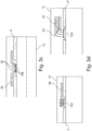
- FIGS. 3 a) - g connecting structures are shown, which make it possible to connect the sensors 100 electrically. It should also be possible to connect more than one sensor 100 at a time. The number is usefully between one and four sensors. In addition, the electrical connection and a signal pre-processing device is shown.
- FIG. 3 a) 1 shows a cross section on the left and on the right a longitudinal section through a pump tube 10.
- a printed circuit board (PCB) or MID accommodates the two bonding wires 100a and 100b, each of a sensor 100 placed on the inner tube 4 of the pump tube 10.
- the bonding wires 100 a, 100 b are applied as a ball by means of wire bonding and are rewired on the printed circuit board 20.
- the (flexible) circuit board 20 is located directly above the sensor 100 and has a hole or lead-through 21 for the bonding wires 100a, 100b.
- FIG. 3 b shows a printed circuit board (PCB) or MID 20 next to the sensor 100.
- the bonding wires are attached to the sensor 100 as ball 101 (left) or wedge 102 (right) and rewired on the board.
- passive or active electrical components 22 may already be accommodated on the printed circuit board 20 as a preprocessing device in order to carry out a first filtering or preprocessing.
- FIG. 3 c shows a 3D-MID circuit board 20 as a connector board. This requires no bonding wires for connection and can be soldered or plugged directly onto the sensor 100.
- electrical components 22 may already be provided as a preprocessing device here.
- FIG. 3 d shows a complete sensor assembly 100, which is electrically connected to either a plugged and soldered board 20 or individually insulated wires 23.
- the insulation 24 can be made, for example, via a Teflon sheath, which has an extremely high dielectric strength at a very small thickness.
- FIG. 3 e the electrical connection of a rewiring board 20 at the sensor 100 to a motherboard or other pump electronics 200 in the pump tube 10 is shown.
- This connection is made by infected or soldered galvanic conductor 201 and transmits the sensor data to the pump electronics 200 for further processing.
- the forwarding can also be carried out via 3D-shaped circuit boards (eg MID circuit boards).
- Another way to transfer the data within the pump tube 10 is a wireless communication interface.
- the pump tube 10 has a bearing stator 13, which is in the flow.
- a sensor 100 in this bearing stator 13 is electrically connected via a channel 16 within the stator structure 17.
- lines 100a, 100b are laid through the channel 16 from the sensor 100 to the evaluation or processing electronics 21.
- the channel 16 is in the simplest case a bore through the stator blades 17, which are connected to the pump tube 10.
- FIG. 3 g can be mounted within the pump tube 10 in addition to the actual pressure-sensitive sensor 100 nor a reference pressure sensor 103.
- This sensor 103 is in the simplest case an IC on an electronic board 22 within the pump housing. By means of this pressure sensor 103, fluctuations in the reference pressure in the hermetically sealed pump housing can be detected. The pressure fluctuations can be used to compensate for measurement errors of the actual sensor 100.
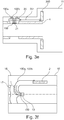
- FIG. 4 shows a simplified representation of the connection of the sensors 100 to a processing device.
- the signals of individual sensors 100 on a pump electronics 300 can be combined and processed via the electrical connections 100a, 100b, 201.
- the rewiring boards 300 may be purely passive or already contain preprocessing.
- the signal from the pressure sensor can be amplified and filtered for signal recording.
- the filters may be mounted in front of and / or behind the amplifier, respectively. Also, the amplifier may be designed as an active filter element.
- the amplified signal can be digitized by an analog-to-digital converter (ADC). After digitization, the waveform can be saved and further filtered as needed. Digital filtering takes up no space in the pump compared to discrete filtering.
- the filters are intended to remove interference from the useful signal. Faults may have their source outside the pump such as EMC or shock. A fault that originates from the pump itself is, for example, the stray magnetic field of the magnet in the pump rotor. Disturbances such as EMC can be filtered via a frequency selection.
- the interference can be filtered out via a correlation filter become.
- the correlation filter can be executed in the flow control or as an active filter element.
- the interference can also be recorded via a dummy pressure sensor.
- the dummy pressure sensor should have the same structure as the pressure sensor, with the difference that it has a different pressure dependence than the pressure sensor. Sensitivity to disturbances should be comparable. By comparing the dummy pressure sensor signal and the pressure sensor signal, the interference can be canceled. The situation is similar with the disturbances caused by the stray field of the pump rotor magnet. Since the position and speed of the rotor magnet is known to the motor driver, this signal can also be deducted.
- FIG. 6 a) shows a plan view of a sensor region 30 with six sensor structures 32, 33, 34th
- FIG. 6 b) shows a schematic representation of a sensor structure 32, 33, 34 consisting of four interconnected to a full bridge sensors.
- the sensors of the sensor structures 32, 33, 34 are arranged in a region 31 of maximum deformation within the sensor region 30.
- four sensors are interconnected to form a full-bridge circuit 32 (measuring bridge) for temperature compensation of the sensors.
- Each full bridge 32 has four bond pads for electrical connection to a processing device.
Abstract
Die vorliegende Erfindung betrifft ein Bauteil zum Führen eines Fluids mit einem Sensor, wobei das Bauteil eine innere und eine äußere Wandung umfasst, wobei die innere Wandung zum Führen des Fluids ausgebildet ist, die äußere Wandung das Bauteil nach außen abschließt und zwischen der inneren und der äußeren Wandung ein Wandbereich ausgebildet ist. Das erfindungsgemäße Bauteil zeichnet sich dadurch aus, dass der Sensor ein elektromechanisches Sensorelement aufweist und im Wandbereich an der inneren Wandung angeordnet ist, wobei der Sensor eingerichtet ist, mittels des Sensorelements einen Grad einer Verformung der inneren Wandung im Bereich des Sensors zu messen und als elektrisches Signal auszugeben, wobei das elektromechanische Sensorelement eine Länge und/oder eine Breite von ≤ 50 µm aufweist.The present invention relates to a component for guiding a fluid with a sensor, wherein the component comprises an inner and an outer wall, wherein the inner wall for guiding the fluid is formed, the outer wall terminates the component to the outside and between the inner and the outer wall is formed a wall portion. The component according to the invention is characterized in that the sensor has an electromechanical sensor element and is arranged in the wall region on the inner wall, wherein the sensor is arranged to measure a degree of deformation of the inner wall in the region of the sensor by means of the sensor element and as electrical Output signal, wherein the electromechanical sensor element has a length and / or a width of ≤ 50 microns.
Description
Die vorliegende Erfindung betrifft ein Bauteil zum Führen eines Fluids mit einem Sensor zur Messung einer Verformung des Bauteils. Weiterhin betrifft die Erfindung ein Verfahren zum Herstellen des Bauteils enthaltend den Sensor. Das betreffende Bauteil kann insbesondere im Bereich von Herzunterstützungssystemen eingesetzt werden.The present invention relates to a component for guiding a fluid with a sensor for measuring a deformation of the component. Furthermore, the invention relates to a method for producing the component containing the sensor. The relevant component can be used in particular in the field of cardiac support systems.
Mit dem heutigen Stand der Technik im Bereich der Herzunterstützungssysteme sind die Anforderungen an die zu integrierende Sensorik gestiegen, die in modernen Herzunterstützungssystemen zunehmend an Bedeutung gewinnen, um einen Patienten sicher und gemäß des individuellen Support-Bedarfs versorgen und unterstützen zu können. Gemeint sind primär jene Anforderungen, die eine blutverträgliche und gleichzeitig zuverlässige Messung verschiedener Kenngrößen zulassen (z.B. Druckmessung, Flussmessung, Materialermüdung, Vibrationsmessung, Anschlagdetektion, Detektion eines Thrombendurchgangs, Detektion und Unterscheidung systematischer und zufälliger Störgrößen).With the current state of the art in the field of cardiac support systems, the demands on integrated sensor technology have increased, which are becoming increasingly important in modern cardiac support systems in order to be able to provide and support a patient safely and according to the individual support needs. These are primarily those requirements that allow a blood compatible and at the same time reliable measurement of different parameters (eg pressure measurement, flow measurement, material fatigue, vibration measurement, impact detection, detection of a Thrombosis, detection and differentiation of systematic and random disturbances).
Gegenwärtig können viele für den Anwender aus technischer als auch klinischer Sicht wichtige Eigenschaften und Zustände eines Herzunterstützungssystems bzw. Patienten aufgrund der verfügbaren Technik nicht erfasst und verarbeitet werden. Das ist zum einen bedingt durch in den Herzunterstützungssystemen angewandte Sensor-Technologie, als auch durch den oftmals kaum verfügbaren Bauraum, der für bestimmte Messgrößen und an verschiedenen Stellen innerhalb eines Herzunterstützungssystems eine sogar oftmals mehrfache Applikation diverser Sensoren erfordert. Des Weiteren müssen häufig strömungstechnische Einbußen oder Einbußen hinsichtlich der hämokompatiblen Blutführung in Kauf genommen werden, da beispielsweise das Einschweißen einer flachen Membran als Aufnahme für die Sensoren erforderlich ist (z.B. Einschränkung der strömungstechnischen Gestaltung, Aktivierung durch Rauheiten einer Schweißnaht/Spalt/Stufe, etc.), oder die geometrische Beschaffenheit der blutführenden Strecke für die Anwendbarkeit der jeweiligen Messapparatur entsprechend angepasst werden muss (z.B. Abflachung der Innenwand, großflächiges ausdünnen einer Rohrwand oder Tangentialkammer, Ausbeulen einer blutführenden Wandung um Bauraum zu schaffen).At present, many technical and clinical features and conditions of a cardiac assist system or patient that are important to the user can not be captured and processed because of the available technology. This is due on the one hand to the sensor technology used in the cardiac support systems, and to the often scarcely available installation space which, for certain measured quantities and at various points within a cardiac support system, requires an often multiple application of various sensors. Furthermore, frequent fluidic losses or losses with regard to the hemocompatible blood guide must be accepted, since, for example, the welding of a flat membrane as a receptacle for the sensors is required (eg restriction of fluidic design, activation by roughness of a weld / gap / step, etc. ), or the geometric nature of the blood-conducting route for the applicability of the respective measuring apparatus must be adjusted accordingly (eg flattening of the inner wall, large thinning a tube wall or Tangentialkammer, bulging a blood-carrying wall to create space).
Zudem muss jedwede Sensorik in dem Einlassbereich oder Auslassbereich einer Blutpumpe elektrisch an das Gesamtsystem angebunden werden. Dazu zählt auch das elektrische Kontaktieren von einzelnen physikalischen Messaufnehmern oder das Verbinden ganzer Baugruppen. Aufgrund enger Platzverhältnisse zwischen Innenwand und Außenwand der Blutpumpe müssen die Sensorelemente und auch die Verdrahtung eine geringe Bauhöhe aufweisen.In addition, any sensors in the inlet area or outlet area of a blood pump must be electrically connected to the overall system. This includes the electrical contacting of individual physical sensors or the connection of entire assemblies. Due to the limited space between the inner wall and the outer wall of the blood pump, the sensor elements and also the wiring must have a low height.
Die Aufgabe der vorliegenden Erfindung ist es, ein Bauteil zum Führen eines Fluids mit einem Sensor, beispielsweise für ein Herzunterstützungssystem, bereitzustellen, welches die oben beschriebenen Probleme löst und wobei der Sensor in das Bauteil derart integriert ist, dass wichtige Zustände eines mit dem Bauteil verbindbaren Fluidsystems, beispielsweise eines Herzunterstützungssystems als auch eines mit dem Herzunterstützungssystem in Wechselwirkung stehenden Patienten, erfasst werden können, die Ausmaße des Bauteils nicht vergrößert werden, der Sensor das Fluid bzw. den Fluidfluss nicht beeinflusst und nicht mit einer Einbauumgebung des Bauteils in Kontakt kommt.The object of the present invention is to provide a component for guiding a fluid with a sensor, for example for a cardiac assist system, which solves the problems described above and wherein the sensor is integrated into the component such that important states of a connectable to the component Fluid system, such as a cardiac assist system as well as a patient interacting with the cardiac assist system, can be detected, the dimensions of the component can not be increased, the sensor does not affect the fluid or the fluid flow and does not come into contact with an installation environment of the component.
Die Aufgabe wird gelöst durch ein Bauteil zum Führen eines Fluids mit einem Sensor nach Anspruch 1 sowie durch ein Verfahren zum Herstellen eines derartigen Bauteils nach Anspruch 12. Vorteilhafte Weiterbildungen des erfindungsgemäßen Bauteils sind in den abhängigen Ansprüchen 2 bis 11 und 13 bis 15 aufgeführt.The object is achieved by a component for guiding a fluid with a sensor according to claim 1 and by a method for producing such a component according to
Das erfindungsgemäße Bauteil zum Führen eines Fluids mit einem Sensor umfasst eine innere und eine äußere Wandung, wobei die innere Wandung zum Führen des Fluids ausgebildet ist, die äußere Wandung das Bauteil nach außen abschließt und zwischen der inneren und der äußeren Wandung ein Wandbereich ausgebildet ist. Das erfindungsgemäße Bauteil zeichnet sich dadurch aus, dass der Sensor ein elektromechanisches Sensorelement aufweist und im Wandbereich an der inneren Wandung angeordnet ist, wobei der Sensor eingerichtet ist, mittels des Sensorelements einen Grad einer Verformung der inneren Wandung im Bereich des Sensors zu messen und als elektrisches Signal auszugeben, wobei das elektromechanische Sensorelement eine Länge und/oder eine Breite von ≤ 50 µm aufweist.The component according to the invention for guiding a fluid with a sensor comprises an inner and an outer wall, wherein the inner wall is designed to guide the fluid, the outer wall terminates the component to the outside and a wall region is formed between the inner and the outer wall. The component according to the invention is characterized in that the sensor has an electromechanical sensor element and is arranged in the wall region on the inner wall, wherein the sensor is arranged to measure a degree of deformation of the inner wall in the region of the sensor by means of the sensor element and as electrical Output signal, wherein the electromechanical sensor element has a length and / or a width of ≤ 50 microns.
Unter einem Sensor wird hier ein Schichtaufbau verstanden, der vorzugsweise in einer ersten Schicht zwei elektrische Kontakte aufweist, die durch einen Spalt voneinander separiert sind. Auf den elektrischen Kontakten kann dann das Sensorelement in einer zweiten Schicht angeordnet sein. Das Sensorelement ist ein elektromechanisches Element, vorzugsweise ein nanostrukturelles Dehnelement, und weist selbst keine weiteren Bauteile, wie z.B. elektrische Leiter, auf. Das Sensorelement erstreckt sich vorzugsweise in einer Querrichtung über den Spalt. Weiterhin kann das Sensorelement im Bereich des Spalts in die erste Schicht hineinragen. Weiterhin umfasst der Sensor vorzugsweise zwei Bond-Pads, wobei jeweils ein Bond-Pad mit einem der elektrischen Kontakte elektrisch kontaktiert ist.A sensor is understood here as a layer structure which preferably has two electrical contacts in a first layer, which are separated from one another by a gap. The sensor element can then be arranged in a second layer on the electrical contacts. The sensor element is an electromechanical element, preferably a nanostructural expansion element, and does not itself comprise any other components, e.g. electrical conductor, up. The sensor element preferably extends across the gap in a transverse direction. Furthermore, the sensor element can protrude into the first layer in the region of the gap. Furthermore, the sensor preferably comprises two bond pads, wherein in each case a bonding pad is electrically contacted with one of the electrical contacts.
Die innere Wandung weist auf der Fluid-führenden Seite auch nach Einbetten des Sensors keine Sensor-bedingten Materialübergänge, Stufen oder Spalte (wie z.B. Schweißnähte o.Ä.) auf.The inner wall has no sensor-related material transitions, steps or gaps (such as welds or the like) on the fluid-leading side even after embedding of the sensor.
Die hier beschriebene Erfindung ist für alle implantierbaren und hämokompatiblen Werkstoffe anwendbar, und ist in der Lage kleinste Auslenkungen (Hübe, Vibrationen, Impulse) ohne invasive Einwirkungen auf ein blutführendes Element zu messen, die mit herkömmlichen Sensoren nicht erfasst werden können (z.B. DMS, Ultraschallsensoren, optische Sensoren), und diese Information auszugeben. Im gleichen Maße verhält es sich mit dem erforderlichen Bauraum, da der angewandte Sensor selbst nur wenige Kubikmikrometer in Anspruch nimmt, somit sehr leicht zu integrieren, und zum Teil in bislang unzugänglichen Strukturen applizierbar ist.The invention described herein is applicable to all implantable and hemocompatible materials, and is capable of measuring minute deflections (strokes, vibrations, pulses) without invasive effects on a blood-carrying element that can not be detected with conventional sensors (eg strain gauges, ultrasonic sensors , optical sensors), and to output this information. To the same extent it behaves with the required space, since the applied sensor itself takes only a few cubic microns, thus very easy to integrate, and can be applied in part in previously inaccessible structures.
In einer vorteilhaften Ausgestaltung der Erfindung kann das Sensorelement ein nanostrukturelles Dehnelement sein, welches stoffschlüssig auf die Kontakte aufgebracht ist, sodass die Kontakte über das Sensorelement elektrisch miteinander kontaktiert sind, wobei die elektrischen Kontakte derart auf die innere Wandung aufgebracht sind, dass sich das Sensorelement bei Verformung der inneren Wandung im Bereich des Sensors mit der inneren Wandung verformt, sodass zwischen den elektrischen Kontakten das elektrische Signal messbar ist.In an advantageous embodiment of the invention, the sensor element may be a nanostructural expansion element, which is cohesively applied to the contacts, so that the contacts are electrically contacted to each other via the sensor element, wherein the electrical contacts are applied to the inner wall, that the sensor element at Deformation of the inner wall in the region of the sensor deformed with the inner wall, so that between the electrical contacts, the electrical signal is measurable.
Weiterhin kann im Wandbereich an der inneren Wandung eine Vielzahl von Sensoren angeordnet sein. Insbesondere können an der inneren Wandung vier Sensoren angeordnet sein, welche vorzugsweise zu einer Voll- oder Halbbrücken-Schaltung miteinander verschaltet sind, um eine Temperaturabhängigkeit der Sensoren zu reduzieren.Furthermore, a plurality of sensors can be arranged in the wall region on the inner wall. In particular, four sensors can be arranged on the inner wall, which are preferably interconnected to form a full or half-bridge circuit, in order to reduce a temperature dependence of the sensors.
Weiterhin kann zwischen der inneren Wandung und den elektrischen Kontakten des Sensors eine elektrische Isolationsschicht angeordnet sein, welche stoffschlüssig mit der inneren Wandung und den elektrischen Kontakten verbunden ist.Furthermore, between the inner wall and the electrical contacts of the sensor, an electrical insulation layer may be arranged, which is materially connected to the inner wall and the electrical contacts.
Das Sensorelement kann insbesondere ein nanokristallines Verbundmaterial (Nanocomposite) aufweisen, welches vorzugsweise mittels Nano-3D-Drucks aufdruckbar ist und dessen Komposition beliebig veränderbar ist. Weiterhin kann das Sensorelement ein Metall und/oder ein Halbleitermaterial aufweisen. Das Sensorelement kann auch ein mit Ladungsträgern dotiertes Metall und/oder ein mit Ladungsträgern dotiertes Halbleitermaterial aufweisen, um eine elektrische Leitfähigkeit und/oder einen elektrischen Widerstand des Sensorelements einzustellen.The sensor element may in particular comprise a nanocrystalline composite material (nanocomposite), which can preferably be imprinted by means of nano-3D printing and whose composition can be changed as desired. Furthermore, the sensor element may comprise a metal and / or a semiconductor material. The sensor element can also have a metal doped with charge carriers and / or a semiconductor material doped with charge carriers in order to to set an electrical conductivity and / or an electrical resistance of the sensor element.
Das elektrische Signal kann insbesondere eine Änderung eines elektrischen Widerstands des Sensors beinhalten.The electrical signal may in particular include a change in an electrical resistance of the sensor.
Vorteilhaft ist es, wenn das Sensorelement eine Länge und/oder eine Breite von ≤ 15µm, insbesondere ≤ 10 µm, insbesondere ≤ 3 µm und/oder eine Dicke von ≤ 50 µm, insbesondere ≤ 15µm, insbesondere ≤ 10 µm, insbesondere ≤ 3 µm aufweist.It is advantageous if the sensor element has a length and / or a width of ≦ 15 μm, in particular ≦ 10 μm, in particular ≦ 3 μm and / or a thickness of ≦ 50 μm, in particular ≦ 15 μm, in particular ≦ 10 μm, in particular ≦ 3 μm having.
Vorzugsweise können die elektrischen Kontakte derart auf die innere Wandung aufgebracht sein, dass zwischen den Kontakten ein Spalt von ≤ 50 µm, insbesondere ≤ 30 µm, insbesondere ≤ 15µm, insbesondere ≤ 10 µm, insbesondere ≤ 3 µm besteht, wobei der Spalt in einer Querrichtung vollständig von dem Sensorelement überdeckt wird.Preferably, the electrical contacts may be applied to the inner wall such that a gap of ≦ 50 μm, in particular ≦ 30 μm, in particular ≦ 15 μm, in particular ≦ 10 μm, in particular ≦ 3 μm, exists between the contacts, the gap being in a transverse direction completely covered by the sensor element.
Weiterhin ist es bevorzugt, wenn der Sensor in einem abgedünnten Bereich der inneren Wandung angeordnet ist. Eine Wandstärke in dem abgedünnten Bereich ist vorzugsweise ≥ 5 µm, insbesondere ≥ 100 µm und/oder ≤ 500 µm, insbesondere ≤ 200 µm.Furthermore, it is preferred if the sensor is arranged in a thinned region of the inner wall. A wall thickness in the thinned region is preferably ≥ 5 μm, in particular ≥ 100 μm and / or ≦ 500 μm, in particular ≦ 200 μm.
Das Bauteil kann insbesondere eine Blutpumpe sein, wobei ein oder mehrere Sensoren im Einlassbereich und/oder im Auslassbereich im Wandbereich an der inneren Wandung der Blutpumpe angeordnet sind, und aus der Verformung der inneren Wandung ein Blutdruck im Einlassbereich und/oder Auslassbereich, eine momentane Durchflussmenge und/oder Laufeigenschaften der Blutpumpe bestimmbar sind.In particular, the component can be a blood pump, wherein one or more sensors in the inlet area and / or outlet area are arranged in the wall area on the inner wall of the blood pump, and from the deformation of the inner wall a blood pressure in the inlet area and / or outlet area, an instantaneous flow rate and / or running properties of the blood pump can be determined.
Das Bauteil kann weiterhin eine Blutpumpe mit einem beweglichen Förderelement sein, wobei ein oder mehrere Sensoren an der inneren Wandung im Wandbereich der Blutpumpe angeordnet sind, und aus der Verformung der inneren Wandung ein Anschlag des Förderelements an der inneren Wandung festellbar ist.The component may further be a blood pump with a movable conveying element, wherein one or more sensors are arranged on the inner wall in the wall region of the blood pump, and from the deformation of the inner wall, a stop of the conveying element on the inner wall can be fixed.
Das Bauteil kann weiterhin eine mechanisch gelagerte Rotationsblutpumpe ist, wobei ein oder mehrere Sensoren im Bereich der Lageraufnahme im Wandbereich an der inneren Wandung angeordnet sind, und aus der Verformung der inneren Wandung eine Lagerkraft und/oder ein Lagerverschleiß bestimmbar ist.The component may further be a mechanically mounted rotary blood pump, wherein one or more sensors are arranged in the region of the bearing receptacle in the wall region on the inner wall, and from the deformation the inner wall, a bearing force and / or a bearing wear can be determined.
Weiterhin kann eine Vielzahl von Sensoren entlang eines Umfangs der inneren Wandung im Wandbereich oder in Bereich der inneren Wandung ähnlicher statischer Druckverhältnisse angeordnet sein. Mithilfe der Vielzahl an Sensoren können Mittelwerte der Messwerte gebildet und so Messungen der Sensoren genauer gestaltet werden.Furthermore, a plurality of sensors can be arranged along a circumference of the inner wall in the wall region or in the region of the inner wall of similar static pressure conditions. With the help of the large number of sensors, averages of the measured values can be formed, thus making measurements of the sensors more accurate.
Gemäß einer weiteren Ausgestaltung der Erfindung können in dem Wandbereich elektrische Verbindungselemente angeordnet sein, über welche der Sensor mit einer Verarbeitungseinrichtung verbunden ist.According to a further embodiment of the invention, electrical connection elements can be arranged in the wall region, via which the sensor is connected to a processing device.
Insbesondere können die Verbindungselemente eine Leiterplatte, wobei ein oder mehrere Sensoren direkt über die elektrischen Kontakte oder über Bonddrähte mit der Leiterplatte verbunden sind, oder einzeln isolierte Leitungen, insbesondere Teflon-isolierte Leitungen, umfassen.In particular, the connecting elements may comprise a printed circuit board, wherein one or more sensors are connected directly to the printed circuit board via the electrical contacts or via bonding wires, or individually insulated wires, in particular Teflon-insulated wires.
Weiterhin können auf der Leiterplatte elektrische Bauelemente zur Vorverarbeitung der elektrischen Signale, insbesondere zur Vorverstärkung angeordnet sein.Furthermore, electrical components for preprocessing the electrical signals, in particular for preamplification, can be arranged on the printed circuit board.
Die vorliegende Erfindung umfasst auch ein Verfahren zur Herstellung eines Bauteils zum Führen eines Fluids mit einem Sensor. Das erfindungsgemäße Verfahren umfasst die folgenden Schritte: Ausbilden einer inneren und einer äußeren Wandung des Bauteils, wobei die innere Wandung zum Führen des Fluids ausgebildet ist und die äußere Wandung ausgebildet ist, das Bauteil nach außen abzuschließen, und die innere und die äußere Wandung derart zusammenfügbar sind, dass sich zwischen der inneren und der äußeren Wandung ein Wandbereich ergibt, Anordnen eines Sensors mit einem elektromechanischen Sensorelement im Wandbereich an der inneren Wandung, wobei der Sensor eingerichtet ist, mittels des Sensorelements einen Grad einer Verformung der inneren Wandung im Bereich des Sensors zu messen und als elektrisches Signal auszugeben, wobei das elektromechanische Sensorelement eine Länge und/oder eine Breite von ≤ 50 µm aufweist, und Zusammenfügen der inneren und äußeren Wandung.The present invention also includes a method for manufacturing a component for guiding a fluid with a sensor. The method according to the invention comprises the following steps: forming an inner and an outer wall of the component, wherein the inner wall is designed to guide the fluid and the outer wall is designed to close the component to the outside, and the inner and the outer wall can be joined together in that a wall region results between the inner and the outer wall, arranging a sensor with an electromechanical sensor element in the wall region on the inner wall, wherein the sensor is arranged, by means of the sensor element to a degree of deformation of the inner wall in the region of the sensor measure and output as an electrical signal, wherein the electromechanical sensor element has a length and / or a width of ≤ 50 microns, and joining the inner and outer wall.
In einer weiteren vorteilhaften Ausgestaltung des erfindungsgemäßen Verfahrens kann vor dem Anordnen des Sensors eine Isolationsschicht im Wandbereich auf die innere Wandung aufgebracht werden. Dies ist insbesondere notwendig, wenn die innere Wandung ein elektrisch leitendes Material aufweist, um einen Kurzschluss zwischen den Kontakten zu verhindern.In a further advantageous embodiment of the method according to the invention, an insulating layer can be applied to the inner wall in the wall region before arranging the sensor. This is particularly necessary if the inner wall has an electrically conductive material to prevent a short circuit between the contacts.
Das Anordnen des Sensors kann insbesondere die folgenden Schritte umfassen: Aufbringen von elektrischen Kontakten auf der inneren Wandung bzw. auf der isolationsschicht zum Abnehmen des elektrischen Signals und Aufbringen eines elektromechanischen Sensorelements auf den elektrischen Kontakten.The arrangement of the sensor may in particular comprise the following steps: application of electrical contacts on the inner wall or on the insulation layer for removing the electrical signal and application of an electromechanical sensor element on the electrical contacts.
Insbesondere kann das Verfahren umfassen, dass vor dem Anordnen des Sensors an der inneren Wandung oder vor dem Aufbringen der Isolationsschicht eine Wandstärke der Wandung im Bereich des Sensors abgedünnt wird, insbesondere auf eine Wandstärke von ≥ 5 µm, insbesondere ≥ 100 µm und/oder ≤ 500 µm, insbesondere ≤ 200 µm abgedünnt wird.In particular, the method may include that prior to arranging the sensor on the inner wall or before applying the insulation layer, a wall thickness of the wall in the region of the sensor is thinned, in particular to a wall thickness of ≥ 5 μm, in particular ≥ 100 μm and / or ≤ 500 microns, in particular ≤ 200 microns is thinned.
Weiterhin kann das Verfahren umfassen, dass das Sensorelement mittels Nano-3D-Drucks, Aufsputterns oder mittels eines Ätzverfahrens auf die Isolationsschicht aufgebracht wird.Furthermore, the method can include that the sensor element is applied to the insulation layer by means of nano-3D printing, sputtering or by means of an etching process.
Weiterhin kann das Verfahren umfassen, dass eine Empfindlichkeit des Sensorelements durch Einbringen einer höheren oder geringeren Anzahl von Ladungsträgern in das Sensorelement eingestellt wird.Furthermore, the method may include that a sensitivity of the sensor element is adjusted by introducing a higher or lower number of charge carriers into the sensor element.
Im Folgenden werden verschiedene Ausführungsbeispiele eines erfindungsgemäßen Bauteils anhand von Figuren detaillierter beschrieben. Dabei werden verschiedene erfindungswesentliche oder auch vorteilhafte weiterbildende Elemente im Rahmen jeweils eines konkreten Beispiels genannt, wobei auch einzelne dieser Elemente als solche zur Weiterbildung der Erfindung - auch herausgelöst aus dem Kontext des jeweiligen Beispiels und weiterer Merkmale des jeweiligen Beispiels - verwendet werden können. Weiterhin werden in den Figuren für gleiche oder ähnliche Elemente gleiche oder ähnliche Bezugszeichen verwendet, und deren Erläuterung daher teilweise weggelassen.In the following, various embodiments of a component according to the invention will be described in more detail with reference to figures. In this case, various essential to the invention or advantageous further education elements are each referred to in the context of a concrete example, and individual of these elements as such for further development of the invention - also removed from the context of the respective example and other features of each example - can be used. Furthermore, the same or similar reference numerals are used in the figures for the same or similar elements, and their explanation is therefore partially omitted.
Es zeigen
- Figur 1
- a) eine Draufsicht auf einen Teil eines Sensors, b) - c) eine Sensorapplikation an verschiedenen Varianten einer inneren Wandung unterschiedlicher Geometrien,
Figur 2- verschiedene Varianten eines Blutpumpenrohres mit Sensoren,
Figur 3- a) - g) verschiedene Varianten zur elektrischen Anbindung eines Sensors in einem Blutpumpenrohr,
Figur 4- eine vereinfachte Darstellung der Anbindung der Sensoren an eine Verarbeitungseinrichtung,
Figur 5- a) - f) verschiedene Varianten von Signalketten von einem oder mehreren Sensoren zu einem Kommunikationsmodul und
Figur 6- a) Draufsicht auf einen Sensorbereich mit sechs Sensorstrukturen, b) schematische Darstellung einer Sensorstruktur bestehend aus vier zu einer Vollbrücke verschalteten Sensoren.
- FIG. 1
- a) a top view of a part of a sensor, b) c) a sensor application on different variants of an inner wall of different geometries,
- FIG. 2
- different variants of a blood pump tube with sensors,
- FIG. 3
- a) - g) different variants for the electrical connection of a sensor in a blood pump tube,
- FIG. 4
- a simplified representation of the connection of the sensors to a processing device,
- FIG. 5
- a) - f) different variants of signal chains of one or more sensors to a communication module and
- FIG. 6
- a) top view of a sensor region with six sensor structures, b) schematic representation of a sensor structure consisting of four interconnected to a full bridge sensors.
Die folgenden Ausführungsbeispiele beziehen sich vorwiegend auf das Gebiet der Blut-führenden Bauteile, wie z.B. der Blutpumpen für Herzunterstützungssysteme. Die Erfindung beschränkt sich jedoch nicht auf dieses Gebiet, sondern ist auf Fluid-führende Bauteile jeglicher Art anwendbar.The following embodiments relate primarily to the field of blood-carrying components, such as e.g. the blood pumps for cardiac support systems. However, the invention is not limited to this field, but is applicable to fluid-conducting components of any kind.
Ein Ziel der vorliegenden Erfindung in Bezug auf Blut-führende Bauteile ist es, kleinste Auslenkungen (Hübe, Vibrationen, Impulse) ohne invasive Einwirkungen auf ein Blut-führendes Element zu messen, und diese Information auszugeben. Hierzu können spezifische Messkonfigurationen bereitgestellt werden, welche die Messung von Signalen ohne negativen Einfluss auf strömungstechnische als auch hämokompatible Performance eines blutführenden und oder blutfördernden Systems ermöglichen.An object of the present invention with respect to blood-bearing components is to measure minute deflections (strokes, vibrations, pulses) without invasive effects on a blood-conducting element, and to output this information. For this purpose, specific measurement configurations can be provided, which enable the measurement of signals without negative influence on fluidic as well as hemocompatible performance of a blood-carrying and or blood-promoting system.
Dieses Ziel wird erreicht, indem eine oder mehrere Nano-, bzw. Mikrostrukturen (Sensorelement) in einem entsprechenden Abstand und Verlauf auf einen hämokompatiblen, oder beschichteten Werkstoff (Bauteil) aufgebracht werden. Da diese Nanostrukturen als Leiterbahnen dienen, bestehen sie aus einem leitfähigem Material welches mit Hilfe von mikrosytemtechnischen Fertigungsverfahren aufgebracht werden kann (z.B. Lithografisch, Mikroätzen, PEVDM, etc.). Eine weitere Voraussetzung ist die elektronisch passive Applikationsfläche, auf der das Sensorelement appliziert wird, was im Falle einer leitfähigen inneren Wandung zusätzlich eine Isolationsschicht erfordert. Zwischen zwei Leiterbahnen (elektrischen Kontakten) wird dann ein Nanostrukturelles Dehnelement aufgebracht, das bei kleinsten Auslenkungen aufgrund der daraus resultierenden Längenänderung des Dehnelements zu einer veränderten Leitfähigkeit im Dehnelement führt, und somit ein Spannungsdelta zwischen den Leiterbahnen messbar macht.This goal is achieved by one or more nano- or microstructures (sensor element) in a corresponding distance and course to a haemocompatible, or coated material (component) can be applied. Since these nanostructures serve as interconnects, they consist of a conductive material which can be applied with the aid of microsytemtechnical manufacturing processes (eg lithographic, microetching, PEVDM, etc.). Another prerequisite is the electronically passive application surface on which the sensor element is applied, which in the case of a conductive inner wall additionally requires an insulation layer. Between two interconnects (electrical contacts), a nanostructural expansion element is then applied, which leads to a change in conductivity in the expansion element at the smallest deflections due to the resulting change in length of the expansion element, and thus makes a voltage delta between the interconnects measurable.
Folgende Integrationsmöglichkeiten für Sensoren innerhalb eines Blutfördernden oder Blut-führenden Systems sind möglich:The following integration possibilities for sensors within a blood-promoting or blood-leading system are possible:
Zur Bestimmung der momentanen Durchflussmenge in einer Blutpumpe werden im Einlass-, und Auslassbereich eines Blutpumpenrohres 10 eine oder mehrere Sensoren 100 in einer in
Zur Erkennung eines Anschlagevents in einem Herzunterstützungssystem, welches einen Rotor 12 oder ein bewegliches Element zur Förderung/Führung von Blut aufweist, werden ein oder mehrere Sensoren 100 in einer wie in den
Ein Rotor 12 innerhalb eines mechanisch gelagerten Herzunterstützungssystems erzeugt beim Fördern von Blut in Abhängigkeit des momentanen Gegendrucks eine axiale Kraft, die in einem mechanischen Lager 13 aufgenommen wird. Zur Bestimmung der Lagerkraft werden ein oder mehrere Sensoren 100 in der in
Ein Rotor 12 innerhalb eines mechanisch gelagerten Herzunterstützungssystems erzeugt beim Fördern eine axiale Kraft, die in einem mechanischen Lager 13 aufgenommen wirkt. Wird dieser Rotor 12 mit einer bestimmten und als bekannt vorausgesetzten Vorspannung eingebaut (ist üblicherweise erforderlich, um eine Spaltbildung zwischen den Lagerflächen zu vermeiden), ist eine Auslenkung im Lager 13 zu messen (Anwendung 4). Wenn durch Abrieb im Lager 13 die axiale Ausdehnung des Rotors 12 reduziert wird, sinkt dadurch auch die durch die Vorspannung erzeugte Auslenkung am Lagerpunkt 13. Durch die hochauflösende Messung der Sensoren 100 kann somit der Verschleiß an einem Lager 13 detektiert, und entsprechende Maßnahmen eingeleitet werden, falls eine gefährdende Situation vorliegt.A
Die in Anwendung 5 beschriebenen Störgrößen lassen gleichermaßen auf eine Materialermüdung am Lager 13 schließen.The disturbances described in
Da die Sensoren 100 kleinste Auslenkungen erfassen, sind sie auch zur Überwachung der Laufeigenschaften eines Herzunterstützungssystems geeignet (Messung periodischer Schwingungen). Ungewollte Vibrationen oder sporadische Impulse, die z.B. beim Fallen eines Patienten, oder durch eine starke Verzögerung bei z.B. einem Unfall auftreten, können daher erkannt und entsprechend verarbeitet werden.Since the sensors detect 100 smallest deflections, they are also suitable for monitoring the running characteristics of a cardiac assistive system (measurement of periodic oscillations). Unwanted vibrations or sporadic impulses that occur, for example, when a patient falls, or due to a strong delay in, for example, an accident, can therefore be detected and processed accordingly.
Logische Verarbeitung der in Anwendung 7 gemessenen Signale.Logical processing of the signals measured in
Bei einem Thrombendurchgang in einer Blutpumpe sind verschiedene Szenarien denkbar, die zu einer mechanischen Schwingung/Impuls führen. Mit einer schwingungssensitiven Blutpumpe könnte daher ein solches Event erkannt und zur Einleitung entsprechender Maßnahmen verwendet werden.In a thrombosis in a blood pump different scenarios are conceivable, leading to a mechanical vibration / pulse. With a vibration-sensitive blood pump, therefore, such an event could be detected and used to initiate appropriate measures.
Zum Betrieb des Sensors 100 im Blutpumpenrohr 10 oder in der Auslasskammer/Auslassrohr 15 ist eine elektrische Anbindung an eine Verarbeitungseinrichtung notwendig. Die elektrische Anbindung kann über zwischen der äußeren Wandung und der inneren Wandung angeordnete elektrische Verbindungselemente erfolgen. Implantierbare Rotationsblutpumpen bestehen i.d.R. aus einem inneren Pumpenrohr als innerer Wandung, dessen innere Oberfläche das Blut führt. Außerhalb des inneren Pumpenrohrs sind bei fast allen Blutpumpen der Motor oder andere elektronische bzw. elektromechanische Baugruppen untergebracht, z.B. Sensoren, aktive Magnetlagerkomponenten. Teile dieser Sensoren können auch als ungekapselte Messaufnehmer implementiert sein. Zur hermetischen Abdeckung dieser Komponenten wird ebenfalls bei fast allen Rotationsblutpumpen ein äußeres Pumpenrohr bzw. ein Gehäuse als äußere Wandung aufgeschweißt. Innerhalb des Hohlraums (Wandbereich) zwischen innerem und äußerem Pumpenrohr bzw. Gehäuse befinden sich die elektrischen Verbindungselemente.To operate the
In den
In
In
In
Das Signal des Drucksensors kann für die Signalaufnahme verstärkt und gefiltert werden. Die Filter können jeweils vor und/oder hinter dem Verstärker angebracht sein. Auch kann der Verstärker als aktives Filterelement ausgeführt sein. Das verstärkte Signal kann von einem Analog-Digital-Wandler (ADC) digitalisiert werden. Nach der Digitalisierung kann der Signalverlauf gespeichert und bei Bedarf weiter gefiltert werden. Eine digitale Filterung beansprucht im Vergleich zur diskreten Filterung keinen Platz in der Pumpe. Die Filter sollen Störungen aus dem Nutzsignal entfernen. Störungen können ihre Quelle außerhalb der Pumpe haben wie Beispielsweise EMV oder Erschütterungen. Eine Störung die von der Pumpe selbst ausgeht ist zum Beispiel das magnetische Streufeld des Magneten im Pumpenrotor. Störungen wie EMV können über eine Frequenzselektion gefiltert werden. Ist mehr über das Störsignal bekannt, dann kann die Störung über ein Korrelationsfilter herausgefiltert werden. Das Korrelationsfilter kann in der Ablaufsteuerung oder als aktives Filterelement ausgeführt werden. Die Störeinflüsse können auch über einen Dummy-Drucksensor aufgenommen werden. Der Dummy-Drucksensor sollte genauso aufgebaut sein wie der Drucksensor, mit dem Unterschied, dass er eine andere Druckabhängigkeit als der Drucksensor aufweist. Die Sensitivität auf Störungen sollte vergleichbar sein. Durch einen Vergleich des Dummy-Drucksensorsignals und des Drucksensorsignals lassen sich die Störeinflüsse aufheben. Vergleichbar verhält es sich mit den Störungen durch das Streufeld des Pumpenrotormagneten. Da die Position und Geschwindigkeit des Rotormagneten dem Motortreiber bekannt ist, kann dieses Signal ebenfalls herausgerechnet werden.The signal from the pressure sensor can be amplified and filtered for signal recording. The filters may be mounted in front of and / or behind the amplifier, respectively. Also, the amplifier may be designed as an active filter element. The amplified signal can be digitized by an analog-to-digital converter (ADC). After digitization, the waveform can be saved and further filtered as needed. Digital filtering takes up no space in the pump compared to discrete filtering. The filters are intended to remove interference from the useful signal. Faults may have their source outside the pump such as EMC or shock. A fault that originates from the pump itself is, for example, the stray magnetic field of the magnet in the pump rotor. Disturbances such as EMC can be filtered via a frequency selection. If more is known about the interference signal, then the interference can be filtered out via a correlation filter become. The correlation filter can be executed in the flow control or as an active filter element. The interference can also be recorded via a dummy pressure sensor. The dummy pressure sensor should have the same structure as the pressure sensor, with the difference that it has a different pressure dependence than the pressure sensor. Sensitivity to disturbances should be comparable. By comparing the dummy pressure sensor signal and the pressure sensor signal, the interference can be canceled. The situation is similar with the disturbances caused by the stray field of the pump rotor magnet. Since the position and speed of the rotor magnet is known to the motor driver, this signal can also be deducted.
Eine weitere Form von Störungen entsteht bei Vibration oder Beschleinigung der Pumpe. Dieser Störeinfluss kann mit einem Beschleunigungssensor, einem Dummy-Drucksensor oder einem differentiellen Drucksensorpaar gemessen und anschließend gefiltert werden. Werden mehrere Drucksensoren aufgenommen, dann können gemeinsame Elemente der Signalkette mittels eines Multiplexers an die verschiedenen Sensoren angeschlossen werden. Die Position des Multiplexers ist hierbei variabel und kann zum Beispiel nach dem ersten Filter sein.
-
Figur 5 a) zeigt eine Signalkette vom Drucksensor ausgehend bestehend aus Drucktransducer, Filter, Verstärker, ADC, Ablaufsteuerung mit Speicher und Kommunikationsmodul. Die Filter können jeweils weggelassen oder mit angrenzenden Modulen, zum Beispiel dem Verstärker, kombiniert werden. -
Figur 5 b) zeigt eine Signalkette ausgehend vom Drucksensor inklusive Abtastung und Filterung der Störeinflüsse. -
Figur 5 c) zeigt eine Signalkette ausgehend vom Drucksensor mit Drucksensor-Dummy zur Störunterdrückung. -
Figur 5 d) zeigt eine Signalkette mit Drucksensor und Beschleunigungssensor zur Unterdrückung von Schock und Vibration. - In
Figur 5 e) kann durch Einsatz eines Multiplexers die Anzahl der Komponenten reduziert werden. Der Multiplexer kann an den Positionen 1bis 5 positioniert werden. -
Figur 5 f) zeigt eine Anregung des Drucksensors mit einem Anregungssignal. Das Anregungssignal kann zusätzlich mit dem Verstärker oder der Ablaufsteuerung verbunden sein. Dies ermöglicht eine sehr selektive Frequenz- oder Korrelationsfilterung.
-
FIG. 5 a) shows a signal chain from the pressure sensor starting consisting of pressure transducer, filter, amplifier, ADC, flow control with memory and communication module. The filters can each be omitted or combined with adjacent modules, for example the amplifier. -
FIG. 5 b) shows a signal chain starting from the pressure sensor including sampling and filtering of the interference. -
FIG. 5c) shows a signal chain starting from the pressure sensor with pressure sensor dummy for interference suppression. -
FIG. 5 d) shows a signal chain with pressure sensor and acceleration sensor to suppress shock and vibration. - In
FIG. 5 e) By using a multiplexer, the number of components can be reduced. The multiplexer can be positioned at positions 1 to 5. -
FIG. 5 f) shows an excitation of the pressure sensor with an excitation signal. The excitation signal may additionally be connected to the amplifier or the sequence controller. This allows very selective frequency or correlation filtering.
Zur Temperaturkompensation der Sensoren werden üblicherweise Brückenschaltungen, insbesondere aus vier Sensoren, angewandt. Dies ist jedoch nur erforderlich wenn die störenden Einflüsse das Auflösungsvermögen oder die gewünschte Langzeitstabilität negativ beeinflussen. Insbesondere kommen Halb- und Vollbrücken-Schaltungen zum Einsatz.
Claims (15)
dadurch gekennzeichnet, dass
der Sensor ein elektromechanisches Sensorelement aufweist und im Wandbereich an der inneren Wandung angeordnet ist, wobei
der Sensor eingerichtet ist, mittels des Sensorelements einen Grad einer Verformung der inneren Wandung im Bereich des Sensors zu messen und als elektrisches Signal auszugeben, wobei
das elektromechanische Sensorelement eine Länge und/oder eine Breite von ≤ 50 µm aufweist.A component for guiding a fluid with a sensor, wherein the component comprises an inner and an outer wall, wherein the inner wall for guiding the fluid is formed, the outer wall terminates the component to the outside and formed between the inner and the outer wall, a wall portion is
characterized in that
the sensor has an electromechanical sensor element and is arranged in the wall region on the inner wall, wherein
the sensor is arranged to measure by means of the sensor element a degree of deformation of the inner wall in the region of the sensor and output as an electrical signal, wherein
the electromechanical sensor element has a length and / or a width of ≦ 50 μm.
Priority Applications (5)
| Application Number | Priority Date | Filing Date | Title |
|---|---|---|---|
| EP18174341.0A EP3572104A1 (en) | 2018-05-25 | 2018-05-25 | Component for conveying a fluid with a sensor |
| PCT/EP2019/063685 WO2019224401A1 (en) | 2018-05-25 | 2019-05-27 | Component for conducting a fluid having a sensor |
| US17/057,049 US20210361931A1 (en) | 2018-05-25 | 2019-05-27 | Component for conducting a fluid having a sensor |
| CN201980047844.2A CN112423833A (en) | 2018-05-25 | 2019-05-27 | Component for guiding a fluid with a sensor |
| DE112019002663.1T DE112019002663A5 (en) | 2018-05-25 | 2019-05-27 | Component for guiding a fluid with a sensor |
Applications Claiming Priority (1)
| Application Number | Priority Date | Filing Date | Title |
|---|---|---|---|
| EP18174341.0A EP3572104A1 (en) | 2018-05-25 | 2018-05-25 | Component for conveying a fluid with a sensor |
Publications (1)
| Publication Number | Publication Date |
|---|---|
| EP3572104A1 true EP3572104A1 (en) | 2019-11-27 |
Family
ID=62630898
Family Applications (1)
| Application Number | Title | Priority Date | Filing Date |
|---|---|---|---|
| EP18174341.0A Withdrawn EP3572104A1 (en) | 2018-05-25 | 2018-05-25 | Component for conveying a fluid with a sensor |
Country Status (5)
| Country | Link |
|---|---|
| US (1) | US20210361931A1 (en) |
| EP (1) | EP3572104A1 (en) |
| CN (1) | CN112423833A (en) |
| DE (1) | DE112019002663A5 (en) |
| WO (1) | WO2019224401A1 (en) |
Families Citing this family (1)
| Publication number | Priority date | Publication date | Assignee | Title |
|---|---|---|---|---|
| CN113476739B (en) * | 2021-06-07 | 2022-11-08 | 浙江迪远医疗器械有限公司 | Blood pump with detection device |
Citations (5)
| Publication number | Priority date | Publication date | Assignee | Title |
|---|---|---|---|---|
| US6367333B1 (en) * | 1999-05-04 | 2002-04-09 | Apex Medical, Inc. | Notch diaphragm pressure sensor |
| US20170112988A1 (en) * | 2012-11-30 | 2017-04-27 | The Penn State Research Foundation | Smart Tip LVAD Inlet Cannula |
| EP3222206A1 (en) * | 2016-03-23 | 2017-09-27 | ETH Zurich | Method for the manufacturing of a carrying device, carrying device, system for detection of a physical parameter and method for detection of a physical parameter |
| US20170348470A1 (en) * | 2016-06-06 | 2017-12-07 | Abiomed, Inc. | Blood pump assembly having a sensor and a sensor shield |
| US20180085505A1 (en) * | 2016-09-23 | 2018-03-29 | Heartware, Inc. | Blood pump with sensors on housing surface |
Family Cites Families (5)
| Publication number | Priority date | Publication date | Assignee | Title |
|---|---|---|---|---|
| CA2922600A1 (en) * | 2013-08-27 | 2015-03-05 | Quantum Biosystems Inc. | Nano-gap electrode and methods for manufacturing same |
| DE102013114407A1 (en) * | 2013-12-18 | 2015-06-18 | Endress + Hauser Gmbh + Co. Kg | pressure sensor |
| US20160000546A1 (en) * | 2014-07-03 | 2016-01-07 | Elwha Llc | Devices, methods, and systems related to expandable implants |
| DE102015216626A1 (en) * | 2015-08-31 | 2017-03-02 | Siemens Aktiengesellschaft | Pressure sensor arrangement and transmitter for process instrumentation with such a pressure sensor arrangement |
| JP2018040776A (en) * | 2016-09-09 | 2018-03-15 | 株式会社NejiLaw | Sensor structure and component having the same |
-
2018
- 2018-05-25 EP EP18174341.0A patent/EP3572104A1/en not_active Withdrawn
-
2019
- 2019-05-27 CN CN201980047844.2A patent/CN112423833A/en active Pending
- 2019-05-27 WO PCT/EP2019/063685 patent/WO2019224401A1/en active Application Filing
- 2019-05-27 US US17/057,049 patent/US20210361931A1/en active Pending
- 2019-05-27 DE DE112019002663.1T patent/DE112019002663A5/en active Pending
Patent Citations (5)
| Publication number | Priority date | Publication date | Assignee | Title |
|---|---|---|---|---|
| US6367333B1 (en) * | 1999-05-04 | 2002-04-09 | Apex Medical, Inc. | Notch diaphragm pressure sensor |
| US20170112988A1 (en) * | 2012-11-30 | 2017-04-27 | The Penn State Research Foundation | Smart Tip LVAD Inlet Cannula |
| EP3222206A1 (en) * | 2016-03-23 | 2017-09-27 | ETH Zurich | Method for the manufacturing of a carrying device, carrying device, system for detection of a physical parameter and method for detection of a physical parameter |
| US20170348470A1 (en) * | 2016-06-06 | 2017-12-07 | Abiomed, Inc. | Blood pump assembly having a sensor and a sensor shield |
| US20180085505A1 (en) * | 2016-09-23 | 2018-03-29 | Heartware, Inc. | Blood pump with sensors on housing surface |
Also Published As
| Publication number | Publication date |
|---|---|
| WO2019224401A1 (en) | 2019-11-28 |
| DE112019002663A5 (en) | 2021-03-11 |
| US20210361931A1 (en) | 2021-11-25 |
| CN112423833A (en) | 2021-02-26 |
Similar Documents
| Publication | Publication Date | Title |
|---|---|---|
| EP2038627B1 (en) | Force sensor and method for detecting at least one force component | |
| WO2013004438A1 (en) | Method for operating an absolute pressure or relative pressure sensor with a capacitive transducer | |
| DE10017572A1 (en) | Rolling bearings with remote-sensing registration units | |
| DE102011083487A1 (en) | Acceleration sensor has detection unit, which is coupled with seismic mass such that amplitude of deflection movement along direction of deflection is greater than amplitude of detecting motion along direction of detection | |
| DE10160794B4 (en) | Signal processing device for a pressure switch od. Like. | |
| EP1382952B1 (en) | Micro mechanical pressure transducer with sensor at the separating diaphragm of the housing | |
| DE3447396A1 (en) | ELECTRIC PRESSURE | |
| DE102010041170A1 (en) | Valve assembly for brake booster of motor vehicle, has pressure transducer with two pressure sensors that produce respective pressure measured values, where sensors are independently operable from one another and receive similar pressure | |
| DE112014001242T5 (en) | Sensor and method for producing a sensor | |
| EP2954867A1 (en) | Planar logic board for ablation catheter with force measurement functionality | |
| EP3220116B1 (en) | Force sensor device | |
| EP3572104A1 (en) | Component for conveying a fluid with a sensor | |
| EP2823274A1 (en) | Micromechanical measuring element | |
| DE102011002884A1 (en) | Force-and/or pressure-and/or temperature measuring electronic circuit for use in force-and/or pressure- and/or temperature sensors in brake device of motor car, has semi-bridge elements whose metallic resistors form potential divider | |
| WO2010066296A1 (en) | Deformation element for a force-moment sensor | |
| DE102018122522A1 (en) | Pressure sensor with improved strain gauge | |
| EP3384263A1 (en) | Pressure sensor asembly and measurement transducer for process instrumentation with such a pressure sensor assembly | |
| DE102007026827A1 (en) | Single-axis force-torque-sensor for robot-supported manipulation and assembling processes, has extension measuring structure for detecting deformation, realized as part of metal lamination of printed circuit board in deformable area | |
| EP3237866B1 (en) | Pressure transducer and method for operating same | |
| WO2011160794A1 (en) | Piezoresistive force sensor | |
| DE102011017462A1 (en) | Device for measuring difference between pressures of measuring elements arranged on measuring chip, has electrodes that are deflected based on results of pressures and independent to common electrode | |
| WO2014090228A1 (en) | Plug/socket test apparatus | |
| DE102006058269B4 (en) | Method for calibrating at least one pressure sensor and corresponding pressure sensor | |
| DE102005038822A1 (en) | Integrated pressure sensor with capacitive measurement principle e.g. for sensing brake pressure, evaluates capacitive change, caused by brake pressure with pressure sensor provided in form of pressure capsule | |
| DE112014002479B4 (en) | Sensor device |
Legal Events
| Date | Code | Title | Description |
|---|---|---|---|
| PUAI | Public reference made under article 153(3) epc to a published international application that has entered the european phase |
Free format text: ORIGINAL CODE: 0009012 |
|
| AK | Designated contracting states |
Kind code of ref document: A1 Designated state(s): AL AT BE BG CH CY CZ DE DK EE ES FI FR GB GR HR HU IE IS IT LI LT LU LV MC MK MT NL NO PL PT RO RS SE SI SK SM TR |
|
| AX | Request for extension of the european patent |
Extension state: BA ME |
|
| STAA | Information on the status of an ep patent application or granted ep patent |
Free format text: STATUS: THE APPLICATION IS DEEMED TO BE WITHDRAWN |
|
| 18D | Application deemed to be withdrawn |
Effective date: 20200603 |