EP3569915B1 - Strömungsstoppwerkzeug für rohrleitungen - Google Patents
Strömungsstoppwerkzeug für rohrleitungen Download PDFInfo
- Publication number
- EP3569915B1 EP3569915B1 EP19175247.6A EP19175247A EP3569915B1 EP 3569915 B1 EP3569915 B1 EP 3569915B1 EP 19175247 A EP19175247 A EP 19175247A EP 3569915 B1 EP3569915 B1 EP 3569915B1
- Authority
- EP
- European Patent Office
- Prior art keywords
- balloon
- pipeline
- flow
- stopping
- shock absorber
- Prior art date
- Legal status (The legal status is an assumption and is not a legal conclusion. Google has not performed a legal analysis and makes no representation as to the accuracy of the status listed.)
- Active
Links
Images


Classifications
-
- F—MECHANICAL ENGINEERING; LIGHTING; HEATING; WEAPONS; BLASTING
- F16—ENGINEERING ELEMENTS AND UNITS; GENERAL MEASURES FOR PRODUCING AND MAINTAINING EFFECTIVE FUNCTIONING OF MACHINES OR INSTALLATIONS; THERMAL INSULATION IN GENERAL
- F16L—PIPES; JOINTS OR FITTINGS FOR PIPES; SUPPORTS FOR PIPES, CABLES OR PROTECTIVE TUBING; MEANS FOR THERMAL INSULATION IN GENERAL
- F16L55/00—Devices or appurtenances for use in, or in connection with, pipes or pipe systems
- F16L55/10—Means for stopping flow in pipes or hoses
- F16L55/12—Means for stopping flow in pipes or hoses by introducing into the pipe a member expandable in situ
- F16L55/124—Means for stopping flow in pipes or hoses by introducing into the pipe a member expandable in situ introduced radially into the pipe or hose
-
- F—MECHANICAL ENGINEERING; LIGHTING; HEATING; WEAPONS; BLASTING
- F16—ENGINEERING ELEMENTS AND UNITS; GENERAL MEASURES FOR PRODUCING AND MAINTAINING EFFECTIVE FUNCTIONING OF MACHINES OR INSTALLATIONS; THERMAL INSULATION IN GENERAL
- F16K—VALVES; TAPS; COCKS; ACTUATING-FLOATS; DEVICES FOR VENTING OR AERATING
- F16K7/00—Diaphragm valves or cut-off apparatus, e.g. with a member deformed, but not moved bodily, to close the passage ; Pinch valves
- F16K7/10—Diaphragm valves or cut-off apparatus, e.g. with a member deformed, but not moved bodily, to close the passage ; Pinch valves with inflatable member
-
- F—MECHANICAL ENGINEERING; LIGHTING; HEATING; WEAPONS; BLASTING
- F16—ENGINEERING ELEMENTS AND UNITS; GENERAL MEASURES FOR PRODUCING AND MAINTAINING EFFECTIVE FUNCTIONING OF MACHINES OR INSTALLATIONS; THERMAL INSULATION IN GENERAL
- F16L—PIPES; JOINTS OR FITTINGS FOR PIPES; SUPPORTS FOR PIPES, CABLES OR PROTECTIVE TUBING; MEANS FOR THERMAL INSULATION IN GENERAL
- F16L55/00—Devices or appurtenances for use in, or in connection with, pipes or pipe systems
- F16L55/10—Means for stopping flow in pipes or hoses
- F16L55/12—Means for stopping flow in pipes or hoses by introducing into the pipe a member expandable in situ
- F16L55/128—Means for stopping flow in pipes or hoses by introducing into the pipe a member expandable in situ introduced axially into the pipe or hose
- F16L55/132—Means for stopping flow in pipes or hoses by introducing into the pipe a member expandable in situ introduced axially into the pipe or hose the closure device being a plug fixed by radially deforming the packing
- F16L55/134—Means for stopping flow in pipes or hoses by introducing into the pipe a member expandable in situ introduced axially into the pipe or hose the closure device being a plug fixed by radially deforming the packing by means of an inflatable packing
Definitions
- the present invention relates to flow stopping tools for live maintenance and new construction operations on pipelines.
- Pipelines are essential for urban and industrial applications.
- pipelines are used for the transportation of liquids or gases below and above the ground or sea.
- These type of pipelines typically have operating pressures larger than 8 bar (120 psi).
- Other type of pipelines are distribution or utility pipelines with typical operating pressures smaller than or equal to 8 bar (120 psi) and are commonly used for the distribution of gasses and liquids to end users such as living quarters and industrial areas.
- Flow stopping tools are typically used for these type of operations as they allow an operator to insert a stopping device such as an inflatable balloon like element into the pipeline. In this way the operator is not prone to a continuous flow of gasses or liquids that escape once the isolated section is cut.
- Known flow stopping tools comprise an external dome that is mounted on a valve which is connected to a pipeline by means of a saddle or welded socket.
- the external dome facilitates a passage in which a hollow lance can be movably inserted.
- the hollow lance also comprises a passage itself, through which a pressure rod with inflatable balloon-like element can be movably inserted.
- the hollow lance further comprises an introducer shoe at its bottom end which can be introduced into the pipeline via the valve.
- the balloon-like element is pushed downwards towards the introducer shoe, while the balloon-like element is in a deflated state.
- the balloon-like element is inflated until it reaches a final inflation stage in which the balloon-like element exerts sufficient pressure on the inner wall of the pipeline such that a flow in the pipeline can be stopped.
- the balloon-like element of known flow stopping tools usually comprises a hose, which has multiple functionalities. Accordingly, the hose is used to inflate the balloon-like element, to align the balloon-like element in the correct position in the pipeline and to secure the balloon-like element in a position while the balloon-like element is brought into the inflated state.
- the balloon-like element and hose end part may experience a large kinetic force resulting from the pipeline flow in case this flow has a high flow speed.
- the hose may get damaged which may result in a leakage of the medium that is used for inflating the balloon-like element.
- the balloon-like element may be completely ruptured from the hose and will get lost in the pipeline.
- German patent application DE 2923880 relates to a flow stopping tool comprising a balloon which is connected to an insertable pressure rod through a hose.
- the hose comprises joints that are surrounded by a coil spring. The construction of joint and springs facilitate insertion of the balloon into a pipeline, but does not strengthen the connection between the pressure rod and the balloon.
- European patent application EP 0 543 458 describes closing plugs comprising a balloon-like element.
- the balloon-like element is provided with reinforcement wires such that, during inflation, the balloon extends in the radial direction but shortens in the axial direction of the balloon.
- the balloon-like element is further provided with an internal guiding shaft having telescopic moving parts and a spring. The guiding shaft is shortened upon inflation in the axial direction. In this way, the balloon only extends in the radial direction. Such an internal guiding shaft does not strengthen the connection between the pressure rod and the balloon.
- One object of the present invention is to provide a balloon like element for use with the flow stopping tool which eliminates the problems inherent to the hose-balloon connection. This and other objects have been attained according to the present invention.
- a flow stopping tool for pipelines wherein the flow stopping tool comprises an inflatable balloon-like element that is adapted for blocking a flow in the pipeline, and wherein the flow stopping tool further comprises a hose for inflating the balloon-like element with a gas or a fluid.
- a part connecting the hose with the inflatable balloon-like element comprises a shock absorber. This part is located outside the balloon-like element.
- the flow stopping tool may further comprise a stopping tower comprising an external dome that is mounted on a valve which is connected to the pipelines by means of a saddle or welded socket, arranged for introducing the balloon-like element into a pressurized pipeline.
- the stopping tower comprises a moveable, internal hollow lance with an insertion shoe, wherein the movable lance can move inside the external dome.
- the flow stopping tool further comprises a pressure rod that can move inside the movable lance, wherein the pressure rod is in connection to the inflatable balloon-like element.
- the hose thereby comprises a coupling element that is in connection to the pressure rod, such as a threaded coupling.
- the inflatable balloon-like element may be made of a natural reinforced rubber, an elastomer or an elastic material which is able to stop the flow in the pipeline after inflation.
- the pressure rod may be further arranged with a device for measuring the inflation pressure of the balloon-like element and a device for measuring the pressure in the pipeline in front of the balloon like element.
- the balloon-like element has a body part made from rubber which is entirely reinforced with a non-elastic fiber extending from one cross cut end to the other cross cut end of the rubber body of the balloon-like element. If such a balloon like element is inflated, the surface of the balloon like element does not increase. Irrelevant from their sizes, such balloon-like elements require the same internal inflation pressure.
- the balloon-like element can resist a flow inside the pipeline of 5 meter per second.
- the balloon-like element is compatible with a pressure of up to 4 bar.
- the balloon-like element preferably is provided with a flap on one or both of the outer ends of the balloon like element.
- the balloon-like element is adapted to close a pipe having a diameter in the range between 200 and 600 millimeter.
- the flow stopping tool being adapted to be connected to the pipeline, comprises an external dome, an internal hollow moveable lance, and inside the movable lance a moveable pressure rod.
- the movable lance comprises an insertion shoe for insertion of the stopper such as a balloon-like element into a pipeline, wherein the insertion shoe is provided with an angled exit through which the balloon-like element can be properly positioned in a pipeline.
- the bottom part of the introducer shoe is shaped parabolic.
- the shock absorber may comprise a first part that is in connection to the hose, and a second part that is in connection to the inflatable balloon-like element. The second part may thereby be received in the first part, or vice versa.
- the first part of the shock absorber may further comprise a secured coupler that connects the first part of the shock absorber with the hose.
- the second part is arranged such that the second part can move in the longitudinal direction with respect to the first part, or vice versa.
- the first part and/or second part may be provided with one or more resilient members, such as helical springs.
- the first part and/or second part may also be provided with one or more sealing rings or O-rings, for providing sealing means of the shock absorber and hose and thereby preventing leaking of the medium that is used to inflate the balloon-like element.
- the first part may comprise a female-type connector which may comprise a housing made from, for example, stainless steel, titanium, carbon steel, aluminum or brass.
- the second part may comprise a rod which is made from, for example, stainless steel, titanium, carbon steel, aluminum or brass.
- the at least one resilient member may be provided in the housing.
- the parts of the shock absorber are arranged such that a passage is facilitated for the passage of medium used for inflating the balloon-like element.
- the parts of the shock absorber form a part that connects the hose with the inflatable balloon-like element.
- the hose forms a connection that connects the pressure rod with the balloon-like element. That is, one end part of the hose is connected to the pressure rod by means of for instance a threaded coupling. The other end part of the hose is connected to the balloon-like element by means of for instance a coupling forming a conical body.
- the shock absorber in that case may for instance be provided around the part of the hose that is connected with inflatable balloon-like element.
- the balloon-like element may be dragged by the flow in the pipeline.
- the rod may thereby move along inside the housing in the direction of the pipeline flow, and may thereby compress or stretch the at least one resilient member, which has a sufficient spring constant and is made from a sufficient strong material to recoil the kinetic forces that are imposed on the hose-balloon connection during inflation of the balloon-like element in the pipeline, and thereby provide for recoiling means.
- the flow stopping tool according to the first aspect of the invention is therefore able to resist a kinetic force of 9 806,65 N (1000 kgf) or more, preferably 19 613,3 N (2000 kgf) or more, even more preferably 29 419,95 N (3000 kgf) or more, and most preferably 39 226,6 N (4000 kgf) or more.
- shock absorber may comprise any other type of resilient member, system or other type of spring such as a resilient beam or a hydraulic system, thereby providing for said recoiling means.
- a shock absorber wherein the shock absorber is compatible for use with a flow stopping tool for pipelines and arranged according to a shock absorber of a flow stopping tool for pipelines according to the first aspect of the invention.
- the first part of the shock absorber may comprise a secured coupler that connects the first part of the shock absorber with the hose.
- This coupler is arranged for receiving the first part of the shock absorber.
- the secured coupler may comprise threads that fit on a threaded profile that is provided on the first part of the shock absorber.
- the secured coupler facilitates connection means of the shock absorber to the hose and thus allows for easy implementation of the shock absorber onto for instance a hose of an existing flow stopping tool.
- a method for stopping a flow in a pipeline comprising the steps of: installing a flow stopping tool according to the first aspect of the present invention; inserting the balloon-like element into the pipeline by moving the pressure rod in the direction of the pipeline; and inflating the balloon-like element for stopping a flow in the pipeline.
- the following steps are performed prior to installation of the flow stopping tool: mounting a ball valve or a gate valve onto a saddle or welded socket that is mounted onto the pipeline; drilling a hole into the pipeline at a location where the ball valve or gate saddle is mounted onto the pipeline.
- a procedure for creating an isolated section free of flow or a section free of flow within a pressurized pipeline with flow comprising the steps of: installing at least one flow stopping tool onto a pipeline by preference installing a second flow stopping tool onto a pipeline; by preference installing a third flow stopping tool onto a pipeline; by preference installing a fourth flow stopping tool onto a pipeline; wherein all four stopping tools each comprise: an external dome with internal hollow moveable lance for inserting a balloon-like element into a pipeline; a balloon-like element for blocking a pipeline flow, wherein the balloon-like element is made of natural reinforced rubber, an elastomer or an elastic material; means to facilitate inflation of the balloon-like element; a pressure rod that is movably arranged within the internal hollow moveable lance, and wherein at least one of the stopping tools is provided with a shock absorber according to the second aspect of the invention, for securing the balloon-like element of said at least one stopping tool; introducing the at least one balloon-like element
- the following steps are performed: mounting up to four ball valves or gate valves onto welded sockets or saddles that are on the pipeline; drilling a hole into the pipeline at a location where the ball valve or gate valve is mounted on the pipeline.
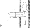
- the flow stopping tool 1 comprises an external dome 2, a moveable lance 3 that can move within external dome 1.
- Movable lance 3 comprises an insertion shoe 4 and a moveable pressure rod 5 with a balloon-like element 6 as closing plug.
- the pressure rod 5 may comprise a device for measuring the inflation pressure of the balloon-like element (not shown). In use, the balloon-like element 6 blocks a flow (F) within a pipeline 7.
- the balloon-like element 6 During insertion of the balloon-like element 6 into the pipeline 7, the balloon-like element 6 is in a deflated state (I). When properly aligned with respect to the pipeline, the balloon-like element 6 is pressurized with a gas or fluid through a hose 8. The balloon-like element 6 is thereby brought into an inflated state (II) such that it closes the passage of the pipeline 7 by providing sufficient pressure on the inner wall of the pipeline 7. During inflation of the balloon-like element 6, the balloon-like element 6 expands and shortens.
- Hose 8 is used to guide compressed air from a pressure source (not shown) into balloon-like element 6.
- Hose 8 comprises an end part 9 that is in connection with the balloon-like element 6.
- the end part 9 functions to secure the balloon-like element 6 in position during the inflation phase. It may appear that the balloon-like element 6 and the hose end part 9 may experience a high initial kinetic force from the pipeline flow (F). For instance, the flow (F) in the pipeline 7 may propagate with a speed of 5 meter per second or higher. As a consequence, the hose end part 9 and/or the balloon-like element 6 may get damaged during the inflation phase, which may result in a leakage of the compressed air. In a worse case, the balloon-like element 6 may be completely ruptured off from the hose 8.
- Flow stopping tool 1 comprises a balloon-like element 6 for blocking a flow (F) in a pipeline 7.
- Pipeline 7 is for instance a gas pipeline or a liquid pipeline.
- An example of a balloon-like element 6 is an inflatable closing plug such as manufactured by the methods according to U.S. Patent US 5,477,886 or according to U.S. Patent Application US 2012/0192983 A1 .
- Flow stopping tool 1 may comprise a balloon-like element 6 according to said referred method.
- Such balloon-like elements are compatible with strong pipeline flows, and are able to resist a back pressure of for example up to 4 bar (58 psi).
- the balloon-like element 6 can be inflated through a hose 8 which is connected to a pressure source (not shown).
- the balloon-like element 6 is inflatable since it is made from an inflatable material, such as an elastic material (e.g. latex or synthetic rubber), and may further comprise a wire or a group of wires 10 (not shown) with low elasticity that extend from one end to the other end of the balloon-like element 6.
- the wire or wires 10 may for instance consist of steel, fiber glass, ultra-high molecular weight polyethylene (e.g. Dyneema®) or aramid (e.g. Twaron® or Kevlar®), which can be spun beforehand to wires, and are adhered to the surface of the balloon.
- Flow stopping tool 1 further comprises an external dome 2 arranged for introducing the balloon-like element 6 into a pipeline 7.
- the external dome 2 may be installed on top of a ball valve or gate valve 11 that is mounted on the pipeline 7.
- the external dome 2 may be provided with a by-pass 12 for bypassing a pipeline flow (F) in pipeline 7.
- the external dome 2 may comprise a moveable internal hollow lance 3 configured to move up and down in the direction as indicated by (T1).
- the moveable lance 3 may comprise a pressure rod 5 configured to move up and down in the direction as indicated by (T2).
- pressure rod 5 is in connection with balloon-like element 6 via a shock absorber 13.
- Pressure rod 5 may be provided with a device for measuring the pressure in front of the of the balloon-like element, comprising for instance a pressure gauge 14. Furthermore, the pressure rod 5 may be connected to the hose 8 via a plate 15 that seals the hollow passage inside the movable lance 3 and prevents leaking of the pipeline flow's medium (F) into the upper part of the movable lance 3.
- a device for measuring the pressure in front of the of the balloon-like element comprising for instance a pressure gauge 14.
- the pressure rod 5 may be connected to the hose 8 via a plate 15 that seals the hollow passage inside the movable lance 3 and prevents leaking of the pipeline flow's medium (F) into the upper part of the movable lance 3.
- the movable lance 3 may comprise an insertion shoe 4 with an exit 16 for facilitating the insertion of the balloon-like element 6 into pipeline 7 through exit 16.
- the bottom part 17 of insertion shoe 8 may be shaped parabolic. This has the advantage that the balloon-like element 6 does not get stuck or damaged during insertion of the balloon-like element 6 into pipeline 7.
- balloon-like element 6 may be provided with a flap 18 which protects the balloon-like element 6 during initial contact with pipeline 7 during inflation. Flap 18 may be made from a rubber material. Balloon-like element 6 may also be provided with a flap 18 at either sides of the balloon-like element 6.
- the balloon-like element 6 is inserted into the pipeline 7 by moving the pressure rod 5 towards the pipeline 7.
- the balloon like element 6 starts in the deflated state (I) and is inserted into the pipeline 7 through movement of the movable lance 3.
- the balloon-like element 6 is thus pushed into the bottom part 17 of the introducer shoe 4 which was inserted into pipeline 7.
- the balloon-like element 6 is further advanced into pipeline 7, which is shown in Figure 2 .
- the balloon-like element 6 may be inserted into the pipeline 7, with the flow (F) or against the flow.
- the balloon-like element is inserted with the flow, as shown in Figure 2 .
- the balloon-like element 6 When properly aligned with respect to the pipeline 7, the balloon-like element 6 is pressurized with a medium like air or a fluid bringing the balloon-like element 6 in the inflated state (II).
- the medium used for inflation may be compressible or incompressible, for example air, nitrogen, hydraulic oil or water.
- the balloon-like element 6 is thereby brought into an inflated state (II) such that the balloon-like element 6 closes the passage of the pipeline 7 by providing sufficient pressure on the inner wall of the pipeline 7.
- the balloon-like element Due to the non-elastic fibers that are embodied in the wall of the rubber body of the balloon like element 6 and the spring mechanism that extends from one end to the other end inside the balloon like element, the balloon-like element shortens while it expands, as the expansion of the internal volume is limited by the applied and embodied fibers onto the rubber wall of the balloon like element 6, the balloon like element can be inflated to a high inflation pressure and will create sufficient shear resistance in order to properly and safely block the pressure and pipeline flow (F).
- FIG. 3A shows the balloon-like element 6, in greater detail.
- the group of wires 10 are visible.
- the hose 8 and a part connecting the hose 8 with the inflatable balloon-like element 6 is visible.
- the hose thereby comprises a coupling element that is in connection to the pressure rod 5, which in this exemplary embodiment is a threaded coupling 19.
- the part connecting the hose 8 with the inflatable balloon-like element 6 comprises a shock absorber 13.
- a plane A-A is indicated, which will be the plane of reference for the Figures 3B-E .
- the shock absorber 13 is provided outside the balloon-like element 6, which is also apparent from Figures 3A-C .
- the shock absorber 13 connects the hose 8 with the balloon-like element 6, such that the shock absorber 13 strengthens the otherwise fragile hose-balloon connection.
- Shock absorber 13 comprises a first part that is in connection to the hose 8, and a second part that is in connection to the inflatable balloon-like element 6.
- the second part may be received in the first part or vice versa.
- the first part comprises a female-type connector 20 comprising a housing 21.
- Housing 21 may be made from, for example, stainless steel, titanium, carbon steel, aluminum or brass.
- Housing 21 receives the second part which is in the present exemplary embodiment a hollow rod 22.
- Rod 22 may be made from, for example, stainless steel, titanium, carbon steel, aluminum or brass.
- the second part of the shock absorber 13 further comprises a conical body 23 which is in direct connection to the balloon-like element 6.
- the first and second part of the shock absorber 13 are arranged such that the first part and second part can move in the longitudinal direction with respect to one another.
- the longitudinal direction is indicated by direction arrow (L).
- the rod 22 can move in housing 21 in the longitudinal direction.
- Housing 21 is provided with at least one resilient member.
- housing 21 is provided with a resilient member which is a helical spring 24.
- a resilient member which is a helical spring 24.
- the balloon-like element 6 is dragged into the direction of the flow (F'), which in this example corresponds to pipeline flow (F).
- rod 22 moves along this direction in housing 21, and thereby compresses helical spring 24.
- Helical spring 24 has a sufficient spring constant and is made from a sufficient strong material to recoil the kinetic forces that are imposed on the hose-balloon connection during inflation of the balloon-like element 6 into the pipeline 7, and thereby provide for a recoiling force.
- shock absorber 13 provides further securing means to secure the balloon-like element 6 into position in the pipeline 7 and prevents the balloon-like element 6 to be ruptured off from the flow stopping tool 1.
- a helical spring is used as resilient member
- other resilient members, systems or other type of springs may be used, for instance a resilient beam or a hydraulic or pneumatic system.
- one ore more helical springs or other type of resilient members may also be located at the other side of housing 21 and may be attached to housing 21 and rod 22. The helical spring thereby may be stretched instead of compressed in case the balloon-like element 6 is introduced in pipeline 7. In this configuration, the at least one helical spring still provides for a recoiling force.
- the shock absorber 13 may comprise a combination of resilient members located at said two locations in housing 21.
- Housing 21 may be further provided with one or more sealing rings or O-rings 25.
- the sealing rings 25 are attached to the end of rod 22. Sealing rings 25 seals the rod 22 in housing 21 and thereby prevent leakage of the medium that is used for inflating the balloon-like element.
- the first part of the shock absorber 13 may comprise a secured coupler 26 that connects the first part of the shock absorber 13 with the hose 6.
- Coupler 26 is arranged for receiving the first part of the shock absorber 13.
- Coupler 26 may for instance have a threaded profile 27.
- Coupler 26 may easily be mounted onto hose 6 and thereby facilitates connection means of the shock absorber 13 to the hose 6. Secured coupler 26 thus allows for easy implementation of the shock absorber 13 onto the hose of existing flow stopping tools.
- secured coupler 26 and the parts of the shock absorber are arranged such that a passage 28 is facilitated for the passage of medium used for inflating the balloon-like element.
- a similar passage may also be used for guiding the hose 8, such that the hose 8 is connected to the balloon-like element 6.
- the hose 8 forms a connection that connects the pressure rod 5 with the balloon-like element 6. That is, one end part of the hose 8 is connected to the pressure rod 5 by means of for instance a threaded coupling. The other end part of the hose 8 is connected to the balloon-like element 6 by means of for instance a coupling forming a conical body 23.
- the shock absorber in that case is then provided around the part of the hose 8 that is connected with inflatable balloon-like element 6.
- Figure 3D shows the unstressed starting position (G) of shock absorber 13.
- the energy stored in shock absorber 13 as a result of the potential kinetic force onto the balloon is minimum, corresponding for instance to an unstretched or uncompressed helical spring 24.
- the balloon-like element is in rest. Shock absorber 13 is brought into a stressed state (E) once the balloon-like element starts to experience a force, from instance from the flow (F) in pipeline 7.
- the helical spring 24 is compressed in this state in the shock absorber 13.
- energy will be stored in the shock absorber 13, thereby absorbing the energy from flow (F) in pipeline 7. Said gained potential energy is subsequently used for recoiling balloon-like element 6 in pipeline 7.
- shock absorber 13 allows the balloon-like element 6 to absorb higher kinetic forces and energy, generated by the flow, than conventional flow stopping tools.
- a flow stopping tool for a pipe diameter of 300 mm provided with said shock absorber can resist a force generated by a pressure of 4 bar and a flow speed of 5 meter per second.
- the flow stopping tool according to the present invention can withstand such a force, whereas conventional flow stopping tools in which the balloon-like element is merely secured by a hose are not compatible with said strong flows.
- the balloon-like element 6 with shock absorber 13 is suitable for resisting a kinetic force of 9 806,65 N (1000 kgf) or more, preferably 19 613,3 N (2000 kgf) or more, even more preferably 29 419,95 N (3000 kgf) or more, and most preferably 39 226,6 N (4000 kgf) or more.
- the present invention is of particular advantage for flow stopping tools comprising relatively large balloon-like elements, for example, balloon-like elements having a diameter when inflated of about 250 mm or higher, like for example in the range between 250 and 600 millimeter, and adapted to close pipes in the range between 250 and 600 mm.
- a flow stopping tool 1 may be performed as follows: a gate valve or ball valve 11 may be mounted onto the pipeline 7. Subsequently, a hole may be drilled into the pipeline 7 at the location on the pipeline 7 where a gate valve or ball valve 11 is mounted.
- Figure 4 shows four flow stopping tools 1a, 1b, 1c and 1d that are used to create an isolated section 29 with no flow within a pipeline 7. Isolated section 29 may be created for several different reasons, e.g. isolated section 29 requires maintenance.
- Prior to installation of the flow stop tool branched saddles or welded sockets 11a, 11b, 11c and 11d may be mounted onto the pipeline 7. Alternatively gate or ball valves may be mounted onto the saddles.
- a hole may be drilled into the pipeline 7 at each location on the pipeline 7 where a gate valve or ball valve is mounted.
- External domes 2a, 2b, 2c, 2d are installed onto the gate valves 11a, 11b, 11c and 11d respectively.
- Each external dome 11a, 11b, 11c and 11d is arranged for the insertion and passage of a pressure rod 5a, 5b, 5c and 5d with a balloon-like element 6a, 6b, 6c and 6d respectively connected to pressure rods 5a, 5b, 5c and 5d.
- Each external dome 2a, 2b, 2c and 2d may comprise a device for measuring the pressure inside the balloon-like element, comprising for instance a pressure gauge 14a, 14b, 14c, 14d which are respectively in connection with the pressure rod 5a, 5b, 5c and 5d.
- Each external dome may further be provided with a by-pass 12a, 12b, 12c and 12d for bypassing a pipeline flow (F) in pipeline 7, purging nitrogen gas or flare gas from isolated section 29.
- At least one of the stopping towers may be a stopping tower according to the present invention. That is, at least one of the stopping towers, for example stopping tower 1a, comprises a shock absorber 13, connecting the pressure rod with the balloon-like element.
- stopping towers 1a, 1b, 1c and 1d may be provided with a shock absorber 13.
- the other stopping towers for instance stopping towers 1b, 1c and 1d, have a balloon-like element that is in connection to the pressure rod merely via a hose 8b, 8c, and 8d respectively.
- a first balloon-like element 6a, 6b, 6c or 6d of one of the flow stopping tools 1a, 1b, 1c or 1d is inserted into pipeline 7, with the flow or into the direction of the flow and is subsequently brought into the inflated state.
- this stopping tower is provided with a shock absorber 13.
- the remaining balloon-like elements can be introduced into pipeline 7. Placement of these remaining balloon-like elements 6b, 6c and 6d may be performed simultaneously or one after the other, and may be performed with the flow or into the direction of the flow.
- the isolated section 29 is free of flow whereby the medium can be removed from the isolated section 29 such that the isolated section 29 can be opened and approached.
- the balloon-like elements 6a, 6b, 6c and 6d may be deflated and retracted from the pipeline 7.
- each stopping tower such as stopping towers 1a, 1b, 1c and 1d, may be located at any desired distance with respect to one another, depending on the circumstances such as the available space in the trench.
Landscapes
- Engineering & Computer Science (AREA)
- General Engineering & Computer Science (AREA)
- Mechanical Engineering (AREA)
- Pipe Accessories (AREA)
Claims (13)
- Strömungsstoppwerkzeug (1) für Rohrleitungen, das Folgendes umfasst:- ein aufblasbares ballonartiges Element (6), das zum Blockieren einer Strömung (F) in einer Rohrleitung (7) angepasst ist;- einen Stoppturm, der zum Einführen des ballonartigen Elements in die Rohrleitung angeordnet ist; eine Druckstange (5), die innerhalb des Stoppturms beweglich angeordnet ist;- einen Schlauch (8) zum Aufblasen des ballonartigen Elements mit einem Gas oder einem Fluid, wobei ein erstes Ende des Schlauches mit der Druckstange in Verbindung steht, dadurch gekennzeichnet, dass ein zweites Ende des Schlauches mit einem Stoßdämpfer (13) in Verbindung steht, wobei der Stoßdämpfer mit dem ballonartigen Element in Verbindung steht und zwischen dem zweiten Ende des Schlauches und dem ballonartigen Element bereitgestellt ist.
- Strömungsstoppwerkzeug nach Anspruch 1, wobei der Stoßdämpfer Folgendes umfasst:- einen ersten Teil (20), der mit dem zweiten Ende des Schlauches in Verbindung steht;- einen zweiten Teil (22), der mit dem aufblasbaren ballonartigen Element in Verbindung steht; wobei der zweite Teil in dem ersten Teil aufgenommen wird oder umgekehrt, und wobei der erste und der zweite Teil angeordnet sind, um sich in der Längsrichtung relativ zueinander zu bewegen.
- Strömungsstoppwerkzeug nach Anspruch 2, wobei der erste Teil und/oder der zweite Teil mit einem oder mehreren elastischen Bauteilen (24) versehen sind.
- Strömungsstoppwerkzeug nach Anspruch 3, wobei wenigstens ein elastisches Bauteil eine Schraubenfeder (24) ist.
- Strömungsstoppwerkzeug nach einem der Ansprüche 2-4, wobei der erste und/oder der zweite Teil mit einem oder mehreren Dichtringen (25) versehen sind.
- Strömungsstoppwerkzeug nach einem der Ansprüche 2-5, wobei der erste Teil des Stoßdämpfers ein Gehäuse (21) umfasst und wobei der zweite Teil des Stoßdämpfers eine Stange (22) umfasst.
- Strömungsstoppwerkzeug nach einem der Ansprüche 2-6, wobei das Strömungsstoppwerkzeug ferner einen gesicherten Koppler (26) umfasst, der den ersten Teil des Stoßdämpfers mit dem zweiten Ende des Schlauches verbindet.
- Strömungsstoppwerkzeug nach einem der vorhergehenden Ansprüche, wobei das ballonartige Element zum Standhalten einer kinetischen Kraft von wenigstens 9 806,65 N (1000 kgf), bevorzugt wenigstens 19 613,3 N (2000 kgf), noch stärker bevorzugt wenigstens 29 419,95 N (3000 kgf) und am stärksten bevorzugt wenigstens 39 226,6 N (4000 kgf) geeignet ist.
- Strömungsstoppwerkzeug nach einem der vorhergehenden Ansprüche, wobei das ballonartige Element angepasst ist, um ein Rohr, das einen Durchmesser in dem Bereich zwischen 250 und 600 Millimeter aufweist, zu schließen.
- Strömungsstoppwerkzeug nach einem der vorhergehenden Ansprüche, wobei der Stoppturm Folgendes umfasst:- eine bewegliche Innenlanze (3), wobei die bewegliche Innenlanze einen Durchgang für eine Einsetzung der Druckstange umfasst und wobei die bewegliche Lanze ferner einen Einsetzungsschuh (4) mit einem Ausgang (16) für die Einführung des ballonartigen Elements in die Rohrleitung umfasst;- eine externe Kuppel, die angepasst ist, um in fester Verbindung mit der Rohrleitung zu stehen, wobei die externe Kuppel einen Durchgang für die Einsetzung der beweglichen Innenlanze umfasst.
- Verfahren zum Stoppen eine Strömung in einer Rohrleitung, das die folgenden Schritte umfasst:- Installieren eines Strömungsstoppwerkzeugs (1) nach einem der Ansprüche 1-10 an einer Rohrleitung (7);- Einführen des ballonartigen Elements in die Rohrleitung; Aufblasen des ballonartigen Elements zum Stoppen einer Strömung (F) in der Rohrleitung.
- Vorgehensweise zum Erstellen eines isolierten Abschnitts in einer strömungsfreien Rohrleitung, die die folgenden Schritte umfasst:- Installieren eines ersten Strömungsstoppwerkzeugs (1a) an einer Rohrleitung (7); Installieren eines zweiten Strömungsstoppwerkzeugs (1b) an der Rohrleitung; Installieren eines dritten Strömungsstoppwerkzeugs (1c) an der Rohrleitung;- Installieren eines vierten Strömungsstoppwerkzeugs (1d) an der Rohrleitung; wobei alle vier Stoppwerkzeuge jeweils Folgendes umfassen: ein aufblasbares ballonartiges Element (6a, 6b, 6c, 6d) zum Blockieren einer Strömung (F) in der Rohrleitung;- einen Stoppturm, der zum Einführen des ballonartigen Elements in die Rohrleitung angeordnet ist;- eine Druckstange (5a, 5b, 5c, 5d), die innerhalb des Stoppturms beweglich angeordnet ist;- einen Schlauch (8b, 8c, 8d) zum Aufblasen des ballonartigen Elements mit einem Gas oder einem Fluid; und wobei wenigstens eines der Strömungsstoppwerkzeuge nach einem der Ansprüche 1-10 angeordnet ist;- Einführen des ballonartigen Elements des wenigstens einen Stoppwerkzeugs mit dem Stoßdämpfer (13) als erstes aufzublasendes ballonartiges Element in die Rohrleitung;- Aufblasen des wenigstens einen ballonartigen Elements, um die Strömung in der Rohrleitung zu stoppen.
- Vorgehensweise nach Anspruch 12, wobei vor der Installation der vier Strömungsstoppwerkzeuge die folgenden Schritte durchgeführt werden:- Montieren von vier Kugelhähnen oder Absperrschiebern (11a, 11b, 11c, 11d) auf einer Sattel- oder Schweißmuffe (11a, 11b, 11c, 11d), die an der Rohrleitung befestigt sind;- Bohren eines Lochs in die Rohrleitung an jeder Stelle, an der ein Kugelhahn oder Absperrschieber an der Rohrleitung montiert ist.
Priority Applications (1)
| Application Number | Priority Date | Filing Date | Title |
|---|---|---|---|
| PL19175247T PL3569915T3 (pl) | 2018-05-18 | 2019-05-17 | Narzędzie zatrzymujące przepływ do rurociągów |
Applications Claiming Priority (1)
| Application Number | Priority Date | Filing Date | Title |
|---|---|---|---|
| NL2020957A NL2020957B1 (en) | 2018-05-18 | 2018-05-18 | A flow stopping tool for pipelines |
Publications (2)
| Publication Number | Publication Date |
|---|---|
| EP3569915A1 EP3569915A1 (de) | 2019-11-20 |
| EP3569915B1 true EP3569915B1 (de) | 2021-10-27 |
Family
ID=63080430
Family Applications (1)
| Application Number | Title | Priority Date | Filing Date |
|---|---|---|---|
| EP19175247.6A Active EP3569915B1 (de) | 2018-05-18 | 2019-05-17 | Strömungsstoppwerkzeug für rohrleitungen |
Country Status (7)
| Country | Link |
|---|---|
| US (1) | US11268644B2 (de) |
| EP (1) | EP3569915B1 (de) |
| CA (1) | CA3043705A1 (de) |
| ES (1) | ES2903382T3 (de) |
| HU (1) | HUE057229T2 (de) |
| NL (1) | NL2020957B1 (de) |
| PL (1) | PL3569915T3 (de) |
Families Citing this family (4)
| Publication number | Priority date | Publication date | Assignee | Title |
|---|---|---|---|---|
| CN111806623B (zh) * | 2020-08-07 | 2024-12-20 | 刘洁 | 一种平衡式侧推孔封堵装置及封堵方法 |
| CN112082035B (zh) * | 2020-09-10 | 2021-03-26 | 无锡市正丰建设工程有限公司 | 一种管道应急管堵气囊装置及管道不停产维修方法 |
| CN116269999B (zh) * | 2023-02-28 | 2024-01-05 | 北京大学深圳医院 | 治疗仪控制风速流量的管道装置、系统及控制方法 |
| TWI873895B (zh) * | 2023-10-04 | 2025-02-21 | 祥泰水電股份有限公司 | 不斷水氣球止水系統 |
Family Cites Families (19)
| Publication number | Priority date | Publication date | Assignee | Title |
|---|---|---|---|---|
| US1747933A (en) * | 1928-06-22 | 1930-02-18 | Goodman | Expansion plug for pipes |
| US2811985A (en) * | 1953-11-06 | 1957-11-05 | Jewell W Wells | Pipe line stoppers |
| US3607361A (en) * | 1968-11-15 | 1971-09-21 | Bonded Products Inc | Balloon backing for pipe lining |
| US3842864A (en) * | 1971-10-29 | 1974-10-22 | American Gas Ass | Stopping apparatus for pipe lines |
| DE2712952A1 (de) * | 1977-03-24 | 1978-09-28 | Versorgungs Unternehmen Avu Ag | Vorrichtung zum einfuehren von aufblasbaren absperrblasen in versorgungsleitungen |
| US4458721A (en) * | 1979-02-28 | 1984-07-10 | Brooklyn Union Gas Company | Pipeline flow restrictor |
| DE2923880A1 (de) * | 1979-06-13 | 1980-12-18 | Immanuel Jeschke | Abdichtvorrichtung fuergastransportleitungen |
| US4417598A (en) * | 1983-02-02 | 1983-11-29 | Depirro Mario | Pneumatic valve |
| NL9101900A (nl) * | 1991-11-14 | 1993-06-01 | Beugen J Van Beheer Bv | Werkwijze voor het vervaardigen van een opblaasbare afsluitplug voor leidingen. |
| SE501374C2 (sv) * | 1993-05-07 | 1995-01-30 | Anne Wikengaard Heed | Anordning för blockering av ett flöde i en rörledning |
| US5778919A (en) * | 1993-12-30 | 1998-07-14 | Custom Service Laboratories Of N.J., Inc. | Pipeline flow stopper with dual shafts |
| US5462077A (en) * | 1994-03-31 | 1995-10-31 | Brooklyn Union Gas Co. | Apparatus and method for shutting off fluid flow in a pipe main |
| AUPN581595A0 (en) * | 1995-10-05 | 1995-10-26 | Water Corporation, The | Linestopper |
| NL1009970C2 (nl) * | 1998-08-31 | 2000-03-02 | Beugen Beheer B V Van | Afsluitinrichting voor een leiding. |
| US5996632A (en) * | 1998-12-14 | 1999-12-07 | Aeroquip Corporation | Pressure relief adapter |
| NZ536269A (en) * | 2004-11-01 | 2007-05-31 | Richard Ord | Blocking assembly with inflatable bladder typically for blocking drains and cesspits in event of chemical spills |
| GB0912866D0 (en) | 2009-07-23 | 2009-08-26 | Beugen J Van Beheer Bv | Inflatable closing plug for pipes |
| US9261222B2 (en) * | 2011-11-30 | 2016-02-16 | Swan Holdings, Llc | Anti-kinking device for garden or water hose |
| NL2020958B1 (en) * | 2018-05-18 | 2019-11-25 | Beugen J Van Beheer Bv | A flow stopping tool for pipelines |
-
2018
- 2018-05-18 NL NL2020957A patent/NL2020957B1/en active
-
2019
- 2019-05-17 HU HUE19175247A patent/HUE057229T2/hu unknown
- 2019-05-17 PL PL19175247T patent/PL3569915T3/pl unknown
- 2019-05-17 ES ES19175247T patent/ES2903382T3/es active Active
- 2019-05-17 CA CA3043705A patent/CA3043705A1/en active Pending
- 2019-05-17 US US16/415,078 patent/US11268644B2/en active Active
- 2019-05-17 EP EP19175247.6A patent/EP3569915B1/de active Active
Also Published As
| Publication number | Publication date |
|---|---|
| EP3569915A1 (de) | 2019-11-20 |
| CA3043705A1 (en) | 2019-11-18 |
| ES2903382T3 (es) | 2022-04-01 |
| PL3569915T3 (pl) | 2022-02-21 |
| HUE057229T2 (hu) | 2022-04-28 |
| NL2020957B1 (en) | 2019-11-25 |
| US11268644B2 (en) | 2022-03-08 |
| US20190353292A1 (en) | 2019-11-21 |
Similar Documents
| Publication | Publication Date | Title |
|---|---|---|
| EP3569915B1 (de) | Strömungsstoppwerkzeug für rohrleitungen | |
| US4458721A (en) | Pipeline flow restrictor | |
| NL2020958B1 (en) | A flow stopping tool for pipelines | |
| US6899138B2 (en) | Flexible emergency gas pipeline plug | |
| US6138718A (en) | Apparatus and method for repairing pressure pipes | |
| US7455077B2 (en) | Inflatable plug with flange | |
| US4077435A (en) | Pipeline plugging apparatus | |
| US8936045B2 (en) | Dual inflatable plug assembly | |
| US20090114302A1 (en) | Double Block and Bleed Plug | |
| US8091640B2 (en) | Method and device for cementing a well or a pipe | |
| US6959734B2 (en) | Flow-through inflatable plug | |
| EP0273960B1 (de) | Anordnung mit ventilfunktion | |
| US11719590B2 (en) | Weld test plugs and methods of use | |
| WO2011121330A1 (en) | Improvements in and relating to pipeline repair | |
| WO2020212472A1 (en) | Bi-directional pig for installing a cable in a conduit | |
| RU2730132C2 (ru) | Устройство для герметичного перекрытия внутренней полости нефтепродуктопровода или нефтепровода | |
| CN208546661U (zh) | 一种天然气输送管道用机械抢修装置 | |
| CA3147780C (en) | Weld test plugs and methods of use | |
| US12092256B2 (en) | Pressurized push rod system and device |
Legal Events
| Date | Code | Title | Description |
|---|---|---|---|
| PUAI | Public reference made under article 153(3) epc to a published international application that has entered the european phase |
Free format text: ORIGINAL CODE: 0009012 |
|
| STAA | Information on the status of an ep patent application or granted ep patent |
Free format text: STATUS: THE APPLICATION HAS BEEN PUBLISHED |
|
| AK | Designated contracting states |
Kind code of ref document: A1 Designated state(s): AL AT BE BG CH CY CZ DE DK EE ES FI FR GB GR HR HU IE IS IT LI LT LU LV MC MK MT NL NO PL PT RO RS SE SI SK SM TR |
|
| AX | Request for extension of the european patent |
Extension state: BA ME |
|
| STAA | Information on the status of an ep patent application or granted ep patent |
Free format text: STATUS: REQUEST FOR EXAMINATION WAS MADE |
|
| 17P | Request for examination filed |
Effective date: 20200518 |
|
| RBV | Designated contracting states (corrected) |
Designated state(s): AL AT BE BG CH CY CZ DE DK EE ES FI FR GB GR HR HU IE IS IT LI LT LU LV MC MK MT NL NO PL PT RO RS SE SI SK SM TR |
|
| GRAP | Despatch of communication of intention to grant a patent |
Free format text: ORIGINAL CODE: EPIDOSNIGR1 |
|
| STAA | Information on the status of an ep patent application or granted ep patent |
Free format text: STATUS: GRANT OF PATENT IS INTENDED |
|
| INTG | Intention to grant announced |
Effective date: 20210521 |
|
| GRAS | Grant fee paid |
Free format text: ORIGINAL CODE: EPIDOSNIGR3 |
|
| GRAA | (expected) grant |
Free format text: ORIGINAL CODE: 0009210 |
|
| STAA | Information on the status of an ep patent application or granted ep patent |
Free format text: STATUS: THE PATENT HAS BEEN GRANTED |
|
| AK | Designated contracting states |
Kind code of ref document: B1 Designated state(s): AL AT BE BG CH CY CZ DE DK EE ES FI FR GB GR HR HU IE IS IT LI LT LU LV MC MK MT NL NO PL PT RO RS SE SI SK SM TR |
|
| REG | Reference to a national code |
Ref country code: GB Ref legal event code: FG4D |
|
| REG | Reference to a national code |
Ref country code: CH Ref legal event code: EP |
|
| REG | Reference to a national code |
Ref country code: AT Ref legal event code: REF Ref document number: 1442090 Country of ref document: AT Kind code of ref document: T Effective date: 20211115 |
|
| REG | Reference to a national code |
Ref country code: DE Ref legal event code: R096 Ref document number: 602019008610 Country of ref document: DE |
|
| REG | Reference to a national code |
Ref country code: IE Ref legal event code: FG4D |
|
| REG | Reference to a national code |
Ref country code: NL Ref legal event code: FP |
|
| REG | Reference to a national code |
Ref country code: LT Ref legal event code: MG9D |
|
| REG | Reference to a national code |
Ref country code: ES Ref legal event code: FG2A Ref document number: 2903382 Country of ref document: ES Kind code of ref document: T3 Effective date: 20220401 |
|
| REG | Reference to a national code |
Ref country code: HU Ref legal event code: AG4A Ref document number: E057229 Country of ref document: HU |
|
| PG25 | Lapsed in a contracting state [announced via postgrant information from national office to epo] |
Ref country code: RS Free format text: LAPSE BECAUSE OF FAILURE TO SUBMIT A TRANSLATION OF THE DESCRIPTION OR TO PAY THE FEE WITHIN THE PRESCRIBED TIME-LIMIT Effective date: 20211027 Ref country code: LT Free format text: LAPSE BECAUSE OF FAILURE TO SUBMIT A TRANSLATION OF THE DESCRIPTION OR TO PAY THE FEE WITHIN THE PRESCRIBED TIME-LIMIT Effective date: 20211027 Ref country code: FI Free format text: LAPSE BECAUSE OF FAILURE TO SUBMIT A TRANSLATION OF THE DESCRIPTION OR TO PAY THE FEE WITHIN THE PRESCRIBED TIME-LIMIT Effective date: 20211027 Ref country code: BG Free format text: LAPSE BECAUSE OF FAILURE TO SUBMIT A TRANSLATION OF THE DESCRIPTION OR TO PAY THE FEE WITHIN THE PRESCRIBED TIME-LIMIT Effective date: 20220127 |
|
| REG | Reference to a national code |
Ref country code: SK Ref legal event code: T3 Ref document number: E 39123 Country of ref document: SK |
|
| PG25 | Lapsed in a contracting state [announced via postgrant information from national office to epo] |
Ref country code: IS Free format text: LAPSE BECAUSE OF FAILURE TO SUBMIT A TRANSLATION OF THE DESCRIPTION OR TO PAY THE FEE WITHIN THE PRESCRIBED TIME-LIMIT Effective date: 20220227 Ref country code: SE Free format text: LAPSE BECAUSE OF FAILURE TO SUBMIT A TRANSLATION OF THE DESCRIPTION OR TO PAY THE FEE WITHIN THE PRESCRIBED TIME-LIMIT Effective date: 20211027 Ref country code: PT Free format text: LAPSE BECAUSE OF FAILURE TO SUBMIT A TRANSLATION OF THE DESCRIPTION OR TO PAY THE FEE WITHIN THE PRESCRIBED TIME-LIMIT Effective date: 20220228 Ref country code: NO Free format text: LAPSE BECAUSE OF FAILURE TO SUBMIT A TRANSLATION OF THE DESCRIPTION OR TO PAY THE FEE WITHIN THE PRESCRIBED TIME-LIMIT Effective date: 20220127 Ref country code: LV Free format text: LAPSE BECAUSE OF FAILURE TO SUBMIT A TRANSLATION OF THE DESCRIPTION OR TO PAY THE FEE WITHIN THE PRESCRIBED TIME-LIMIT Effective date: 20211027 Ref country code: HR Free format text: LAPSE BECAUSE OF FAILURE TO SUBMIT A TRANSLATION OF THE DESCRIPTION OR TO PAY THE FEE WITHIN THE PRESCRIBED TIME-LIMIT Effective date: 20211027 Ref country code: GR Free format text: LAPSE BECAUSE OF FAILURE TO SUBMIT A TRANSLATION OF THE DESCRIPTION OR TO PAY THE FEE WITHIN THE PRESCRIBED TIME-LIMIT Effective date: 20220128 |
|
| REG | Reference to a national code |
Ref country code: DE Ref legal event code: R097 Ref document number: 602019008610 Country of ref document: DE |
|
| PG25 | Lapsed in a contracting state [announced via postgrant information from national office to epo] |
Ref country code: SM Free format text: LAPSE BECAUSE OF FAILURE TO SUBMIT A TRANSLATION OF THE DESCRIPTION OR TO PAY THE FEE WITHIN THE PRESCRIBED TIME-LIMIT Effective date: 20211027 Ref country code: EE Free format text: LAPSE BECAUSE OF FAILURE TO SUBMIT A TRANSLATION OF THE DESCRIPTION OR TO PAY THE FEE WITHIN THE PRESCRIBED TIME-LIMIT Effective date: 20211027 Ref country code: DK Free format text: LAPSE BECAUSE OF FAILURE TO SUBMIT A TRANSLATION OF THE DESCRIPTION OR TO PAY THE FEE WITHIN THE PRESCRIBED TIME-LIMIT Effective date: 20211027 |
|
| PLBE | No opposition filed within time limit |
Free format text: ORIGINAL CODE: 0009261 |
|
| STAA | Information on the status of an ep patent application or granted ep patent |
Free format text: STATUS: NO OPPOSITION FILED WITHIN TIME LIMIT |
|
| 26N | No opposition filed |
Effective date: 20220728 |
|
| PG25 | Lapsed in a contracting state [announced via postgrant information from national office to epo] |
Ref country code: AL Free format text: LAPSE BECAUSE OF FAILURE TO SUBMIT A TRANSLATION OF THE DESCRIPTION OR TO PAY THE FEE WITHIN THE PRESCRIBED TIME-LIMIT Effective date: 20211027 |
|
| PG25 | Lapsed in a contracting state [announced via postgrant information from national office to epo] |
Ref country code: SI Free format text: LAPSE BECAUSE OF FAILURE TO SUBMIT A TRANSLATION OF THE DESCRIPTION OR TO PAY THE FEE WITHIN THE PRESCRIBED TIME-LIMIT Effective date: 20211027 |
|
| PG25 | Lapsed in a contracting state [announced via postgrant information from national office to epo] |
Ref country code: MC Free format text: LAPSE BECAUSE OF FAILURE TO SUBMIT A TRANSLATION OF THE DESCRIPTION OR TO PAY THE FEE WITHIN THE PRESCRIBED TIME-LIMIT Effective date: 20211027 Ref country code: LU Free format text: LAPSE BECAUSE OF NON-PAYMENT OF DUE FEES Effective date: 20220517 |
|
| PG25 | Lapsed in a contracting state [announced via postgrant information from national office to epo] |
Ref country code: IE Free format text: LAPSE BECAUSE OF NON-PAYMENT OF DUE FEES Effective date: 20220517 |
|
| P01 | Opt-out of the competence of the unified patent court (upc) registered |
Effective date: 20230518 |
|
| PG25 | Lapsed in a contracting state [announced via postgrant information from national office to epo] |
Ref country code: MK Free format text: LAPSE BECAUSE OF FAILURE TO SUBMIT A TRANSLATION OF THE DESCRIPTION OR TO PAY THE FEE WITHIN THE PRESCRIBED TIME-LIMIT Effective date: 20211027 Ref country code: CY Free format text: LAPSE BECAUSE OF FAILURE TO SUBMIT A TRANSLATION OF THE DESCRIPTION OR TO PAY THE FEE WITHIN THE PRESCRIBED TIME-LIMIT Effective date: 20211027 |
|
| PG25 | Lapsed in a contracting state [announced via postgrant information from national office to epo] |
Ref country code: TR Free format text: LAPSE BECAUSE OF FAILURE TO SUBMIT A TRANSLATION OF THE DESCRIPTION OR TO PAY THE FEE WITHIN THE PRESCRIBED TIME-LIMIT Effective date: 20211027 |
|
| PG25 | Lapsed in a contracting state [announced via postgrant information from national office to epo] |
Ref country code: MT Free format text: LAPSE BECAUSE OF FAILURE TO SUBMIT A TRANSLATION OF THE DESCRIPTION OR TO PAY THE FEE WITHIN THE PRESCRIBED TIME-LIMIT Effective date: 20211027 |
|
| PGFP | Annual fee paid to national office [announced via postgrant information from national office to epo] |
Ref country code: NL Payment date: 20250526 Year of fee payment: 7 |
|
| PGFP | Annual fee paid to national office [announced via postgrant information from national office to epo] |
Ref country code: PL Payment date: 20250507 Year of fee payment: 7 Ref country code: DE Payment date: 20250529 Year of fee payment: 7 |
|
| PGFP | Annual fee paid to national office [announced via postgrant information from national office to epo] |
Ref country code: ES Payment date: 20250602 Year of fee payment: 7 Ref country code: GB Payment date: 20250527 Year of fee payment: 7 |
|
| PGFP | Annual fee paid to national office [announced via postgrant information from national office to epo] |
Ref country code: HU Payment date: 20250515 Year of fee payment: 7 |
|
| PGFP | Annual fee paid to national office [announced via postgrant information from national office to epo] |
Ref country code: IT Payment date: 20250521 Year of fee payment: 7 Ref country code: BE Payment date: 20250527 Year of fee payment: 7 |
|
| PGFP | Annual fee paid to national office [announced via postgrant information from national office to epo] |
Ref country code: FR Payment date: 20250526 Year of fee payment: 7 |
|
| PGFP | Annual fee paid to national office [announced via postgrant information from national office to epo] |
Ref country code: CH Payment date: 20250601 Year of fee payment: 7 |
|
| PGFP | Annual fee paid to national office [announced via postgrant information from national office to epo] |
Ref country code: AT Payment date: 20250505 Year of fee payment: 7 Ref country code: RO Payment date: 20250506 Year of fee payment: 7 |
|
| PGFP | Annual fee paid to national office [announced via postgrant information from national office to epo] |
Ref country code: SK Payment date: 20250505 Year of fee payment: 7 |
|
| PGFP | Annual fee paid to national office [announced via postgrant information from national office to epo] |
Ref country code: CZ Payment date: 20250507 Year of fee payment: 7 |
|
| REG | Reference to a national code |
Ref country code: HU Ref legal event code: HC9C Owner name: J. VAN BEUGEN BEHEER B.V., NL |
|
| REG | Reference to a national code |
Ref country code: AT Ref legal event code: UEP Ref document number: 1442090 Country of ref document: AT Kind code of ref document: T Effective date: 20211027 |