EP0273960B1 - Anordnung mit ventilfunktion - Google Patents
Anordnung mit ventilfunktion Download PDFInfo
- Publication number
- EP0273960B1 EP0273960B1 EP87904572A EP87904572A EP0273960B1 EP 0273960 B1 EP0273960 B1 EP 0273960B1 EP 87904572 A EP87904572 A EP 87904572A EP 87904572 A EP87904572 A EP 87904572A EP 0273960 B1 EP0273960 B1 EP 0273960B1
- Authority
- EP
- European Patent Office
- Prior art keywords
- pipeline
- valve
- shaft
- parking brake
- pressure
- Prior art date
- Legal status (The legal status is an assumption and is not a legal conclusion. Google has not performed a legal analysis and makes no representation as to the accuracy of the status listed.)
- Expired - Lifetime
Links
- 239000012530 fluid Substances 0.000 claims abstract description 14
- 230000008878 coupling Effects 0.000 claims description 12
- 238000010168 coupling process Methods 0.000 claims description 12
- 238000005859 coupling reaction Methods 0.000 claims description 12
- 229920001971 elastomer Polymers 0.000 claims description 12
- 239000000806 elastomer Substances 0.000 claims description 12
- 238000012856 packing Methods 0.000 claims description 8
- 238000004891 communication Methods 0.000 claims description 6
- 230000006854 communication Effects 0.000 claims description 6
- 230000008602 contraction Effects 0.000 claims description 2
- 239000012190 activator Substances 0.000 claims 2
- 230000032258 transport Effects 0.000 description 9
- 230000000903 blocking effect Effects 0.000 description 5
- 230000002787 reinforcement Effects 0.000 description 3
- 238000007789 sealing Methods 0.000 description 2
- 238000004873 anchoring Methods 0.000 description 1
- 238000010276 construction Methods 0.000 description 1
- 230000001419 dependent effect Effects 0.000 description 1
- 238000004519 manufacturing process Methods 0.000 description 1
- 239000002184 metal Substances 0.000 description 1
- 230000008439 repair process Effects 0.000 description 1
- 230000006641 stabilisation Effects 0.000 description 1
- 238000011105 stabilization Methods 0.000 description 1
- 229920002994 synthetic fiber Polymers 0.000 description 1
- 238000004073 vulcanization Methods 0.000 description 1
Images
Classifications
-
- F—MECHANICAL ENGINEERING; LIGHTING; HEATING; WEAPONS; BLASTING
- F16—ENGINEERING ELEMENTS AND UNITS; GENERAL MEASURES FOR PRODUCING AND MAINTAINING EFFECTIVE FUNCTIONING OF MACHINES OR INSTALLATIONS; THERMAL INSULATION IN GENERAL
- F16L—PIPES; JOINTS OR FITTINGS FOR PIPES; SUPPORTS FOR PIPES, CABLES OR PROTECTIVE TUBING; MEANS FOR THERMAL INSULATION IN GENERAL
- F16L55/00—Devices or appurtenances for use in, or in connection with, pipes or pipe systems
- F16L55/10—Means for stopping flow in pipes or hoses
- F16L55/12—Means for stopping flow in pipes or hoses by introducing into the pipe a member expandable in situ
- F16L55/128—Means for stopping flow in pipes or hoses by introducing into the pipe a member expandable in situ introduced axially into the pipe or hose
- F16L55/1283—Plugging pig
-
- Y—GENERAL TAGGING OF NEW TECHNOLOGICAL DEVELOPMENTS; GENERAL TAGGING OF CROSS-SECTIONAL TECHNOLOGIES SPANNING OVER SEVERAL SECTIONS OF THE IPC; TECHNICAL SUBJECTS COVERED BY FORMER USPC CROSS-REFERENCE ART COLLECTIONS [XRACs] AND DIGESTS
- Y10—TECHNICAL SUBJECTS COVERED BY FORMER USPC
- Y10T—TECHNICAL SUBJECTS COVERED BY FORMER US CLASSIFICATION
- Y10T137/00—Fluid handling
- Y10T137/7722—Line condition change responsive valves
- Y10T137/7837—Direct response valves [i.e., check valve type]
- Y10T137/7869—Biased open
Definitions
- the present invention relates to a device with a valve function which can be brought into and out of a pipeline.
- a pig with an axial valve system where the pig can be anchored in a pipeline by means of pins which are inserted through the pipeline walls from the outside and against which the pig is secured.
- the pig according to the patent document shall primarily be used for shut-off of the fluid flow during brief periods of pipeline repairs etc., and can not be permanently installed.
- a blocking pig which features parking brakes and sealing devices for temporary shutoff of a pipeline at a predetermined point.
- the blocking pig however, lacks a separate valve function, and consequently cannot be permanently installed in a pipeline either.
- an internal blocking device for a pipeline which comprises two flanges and a cylinder connecting these.
- an elastic tube has been installed, consisting of a rubber-type, synthetic material, which is reinforced with several layers of metal sheathing.
- an inflatable bellow is mounted which receives pressure medium from pressure bottles located inside the cylinder.
- the tube and the inflatable bellow have a double function in that both shall seal off fluid which flows into the pipeline and anchor the blocking device in the pipeline.
- the blocking device does not feature a separate valve function, and must therefore be inserted into the pipeline each time the pipeline is to be blocked.
- EP-A-0087867 shows a pipeline inflation anchor for sealing a pipeline bore. It comprises a parking brake and seal, a cylindrical wire anchor and a remote controlled valve. When the valve is closed, back pressure in the pipeline first urges the brake/seal against the pipeline inner wall, and subsequently forces the wire anchor into contact.
- An object of the present invention is to provide a device with a valve function which can be brought into and out of an already existing pipeline without having to modify the pipeline, and which can be parked at the desired point and can remain there also during normal operation over an extended period. Moreover, the force exerted by the device on the pipeline during normal operation must be limited, in order to avoid local over-loading at the same time as the device must be safely anchored when the valve is closed and there is a great drop in pressure over the device. Another object is to provide a device comprising a valve which closes automatically and instantly at a given pressure difference and which can also be opened/closed at a signal.
- a device of which the diameter is adapted to a pregiven internal diameter of a pipeline having a valve function which can be brought into and out of the pipeline, and parked within the pipeline comprising a channel for throughflowing fluid, a valve, a parking brake/packer seal unit, and a cylindrical wire anchor with an external diameter which is slightly less than the internal diameter of the pipeline which can be brought to pressure contact with the pipeline as a result of differential fluid pressure caused by closing the valve, characterised in that the valve is medium and/or remote controlled and in that the parking brake/packer seal unit is actuable separately from the valve to exert a limited force on the pipeline.
- Another object is to provide a device of a simple design and low weight which is cheap in production. This can be obtained by locating the valve and parking brake in separate sections with the cylindrical wire anchor in between to connect these and with a spring shaft located in contact with the sections to keep these at a given distance from each other.
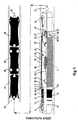
- the figure gives an example of a device according to the invention which is coupled together with a transport vehicle.
- the said transport vehicle is divided into three and consists of a driving carriage 42 and an energy and generator carriage 43.
- the energy and generator carriage 43 features a coupling ball for possible coupling up with a stand-by pig.
- the motor and driving wheels 45 bear against the internal wall of the pipeline and can be driven in both directions. Instead of wheels 45, belts and other driving devices can also be utilized.
- the coupling and communication carriage 41 of the transport vehicle is coupled to the device according to the invention. All couplings between the carriages 41, 42, 43 and between the transport vehicle and the device consist of freely pivotal universal couplings 23, 44.
- the coupling and communication carriage 41 and energy and generater carriage 43 are preferably equipped with freely rotatable guide wheels 16, 24, which run against the internal wall of the pipeline.
- the device is shaped as an extended unit and features a throughflowing fluid channel internally, which is connected with a valve 20.
- the valve 20 is designed to permit opening and closing of the valve in two independent ways. According to the first way, the valve 20 closes automatically if the drop in pressure over the valve 20 exceeds a given limit, and below this limit, it will be open. According to the second way, the valve can be forced open or closed by means of a remote control. Instead of being fluid-operated, the valve 20 can be motor-operated.
- the valve 20 is preferably located in a first section and consists of a valve seat 19 installed as a part of and on the lower side of the enclosing edge of the section and coaxially with the fluid channel, a valve body 25 with contact surface adapted to the valve seat 19, a valve spindle 26, a guiding device 27 on the valve spindle 26, several centring springs 22 and an actuator 21.
- the valve body 25 is attached to the valve spindle 26 so that it can be moved a limited distance in the axial direction of the device.
- the centring springs 22 are located on both sides of the guiding device 27 and arranged to keep the valve in open position when the drop in pressure over the device is within the given limits.
- a communication unit which is connected to the actuator of the valve 20 is located in the first section and makes it possible to open/close the valve 20 by means of an external wireless control. An energy source which is sufficient for the execution of the desired number of closing/opening operations is connected to the valve 20 and the communication unit.
- the device will be secured to the internal wall of the pipeline at the desired point by means of a combined parking brake and a packer seal unit 9 installed in a second section.
- a soft core consisting of an approximately circular elastomer hose 10 which is enclosed by a somewhat more rigid annular seal packing 12.
- the approximately circular room enclosed by the elastomer hose 10 is connected with the throughflowing fluid channel through an aperture 11.
- the annular, preferably reinforced, packer seal unit which encloses the soft core is rigid and will permit passing of welds and other protrusions on the pipeline surface, and will also allow the extremely great tolerances which such a seal packing must satisfy.
- the combined parking brake and packer seal unit 9, hereafter called the parking brake 9, will during normal parking and operation get its holding pressure from an actuator 13. This is accomplished by the parking brake 9 being pressed together in axial direction by the actuator 13, whereby it due to its special composition will expand radially outward to bear firmly against the inner side of the transport pipeline. When the pressure difference over the device increases, the aperture 11 will lead to increasing contact pressure between the parking brake 9 and the pipeline wall.
- the parking brake 9 is installed to keep the entire device parked at a desired place during normal operation with the valve in open position. The parking brake 9 works with limited, given force against the pipeline wall so that this shall not be under heavy stress over a long period of time.
- a separate cylindrical wire anchor 1 has therefore been installed which has the same or a somewhat smaller diameter than the pipeline's internal diameter in the parking zone.
- the wire anchor 1 consists of one or several layers of high-grade wire 2 which is/are attached to clamping rings 3, 4 with conical wedges 7 mounted inside the wires.
- an elastomer 5 which constitutes the elastic core and seal element in the wire anchor 1 will vulcanize the wires 2 and wedges 7 to the clamping rings 3, 4.
- the vulcanization of the elastomer will also enter into the clamping rings 3, 4 and establish a good contact.
- reinforcement in the elastomer 5 will also be relevant. In that case, also the reinforcement will be enclosed by the clamping rings 3, 4.
- the clamping rings 3, 4 will be divided into two to provide for improved anchorage in clamping slots.
- the clamping ring elements 3, 4 will then appropriately clamp the elastomer 5 with reinforcement in each clamping slot.
- Cylindrical roller bearings 24 have been installed on the largest diameter of the clamping rings. The roller bearings 24 prevent the device from jamming when passing tight bends.
- Corresponding roller bearings 8 are also located on the two other tops to prevent jamming in the bends.
- the wire anchor 1 is preferably installed between the two abovementioned sections, connecting these.
- a spring shaft 15 is installed which is preferably located centrally in the device, and is fastened by means of rigid stays 32 in each end which are connected to the clamping rings 3, 4 of the section.
- the spring shaft 15 preferably consists of two tubes 28, 29 and a spring 30 clamped between these.
- a sleeve 31 encloses the shaft elements 15 so that they can only be moved in relation to each other in axial direction. With the shaft 15 in mounted position, the spring 15 exerts a pre-stressing force against the tube ends 28, 29. Elastomers have been installed between the shaft ends 15 and the stays 32.
- the shaft 15 is mounted with spring action in axial direction to compensate for the contraction which must necessarily be present during full differential pressure to provide for sufficient contact between the wire anchor and the pipeline.
- a communication unit has been installed in the hollow shaft 15, which can be wireless-controlled and is in contact with the actuator 13, 14 of the parking brake 9, and can activate this. Also the energy source of the actuator 13, 14 may then be stored in the hollow shaft 15.
- the device is transported to parking position in the pipeline by being coupled together with the transport vehicle by means of a coupling ball, and is brought by this to the desired position.
- the device features several stabilization wheels 16 in the front and back.
- energy is supplied from the transport vehicle to the actuator 13, 14, unless energy is stored in the hollow room of the spring shaft 15.
- the transport vehicle is disconnected and removed.
- the device preferably features coupling balls 23 in both ends so that it can be removed again in any direction. Centrically in the couplings 23, there are connections which enables the vehicle to activate or partly activate the valve 20 and parking brake 9 respectively.
Landscapes
- Engineering & Computer Science (AREA)
- General Engineering & Computer Science (AREA)
- Mechanical Engineering (AREA)
- Transmission Of Braking Force In Braking Systems (AREA)
- Valves And Accessory Devices For Braking Systems (AREA)
- Pipe Accessories (AREA)
- Catching Or Destruction (AREA)
- Fluid-Driven Valves (AREA)
Claims (14)
Applications Claiming Priority (2)
| Application Number | Priority Date | Filing Date | Title |
|---|---|---|---|
| NO862775A NO174785C (no) | 1986-07-09 | 1986-07-09 | Anordning med ventilfunksjon |
| NO862775 | 1986-07-09 |
Publications (2)
| Publication Number | Publication Date |
|---|---|
| EP0273960A1 EP0273960A1 (de) | 1988-07-13 |
| EP0273960B1 true EP0273960B1 (de) | 1991-02-27 |
Family
ID=19889056
Family Applications (1)
| Application Number | Title | Priority Date | Filing Date |
|---|---|---|---|
| EP87904572A Expired - Lifetime EP0273960B1 (de) | 1986-07-09 | 1987-07-08 | Anordnung mit ventilfunktion |
Country Status (7)
| Country | Link |
|---|---|
| US (1) | US4941511A (de) |
| EP (1) | EP0273960B1 (de) |
| JP (1) | JPH0726713B2 (de) |
| DE (1) | DE3768236D1 (de) |
| DK (1) | DK123688A (de) |
| NO (1) | NO174785C (de) |
| WO (1) | WO1988000313A1 (de) |
Families Citing this family (19)
| Publication number | Priority date | Publication date | Assignee | Title |
|---|---|---|---|---|
| DE3612498A1 (de) * | 1986-04-14 | 1987-10-29 | Norske Stats Oljeselskap | Selbstfahrendes fahrzeug fuer rohrleitungen |
| US5219244A (en) * | 1991-02-13 | 1993-06-15 | Fmc Corporation | Subsea pipeline pig launching system |
| US5267466A (en) * | 1991-09-26 | 1993-12-07 | Ford Motor Co. | Apparatus and method for calibrating a suspension control module |
| US5327963A (en) * | 1991-10-30 | 1994-07-12 | The Gates Rubber Company | Tubular coupling device |
| NO178276C (no) * | 1992-12-01 | 1996-02-21 | Ole Molaug | Rörtraktor |
| DE4312942C1 (de) * | 1993-04-21 | 1994-11-17 | Bbc Reaktor Gmbh | Einrichtung zum Prüfen und/oder Bearbeiten einer Rohrleitung von innen |
| US5660202A (en) * | 1993-12-15 | 1997-08-26 | Institute Of Gas Technology | Process and apparatus for insertion of robots in gas distribution systems |
| EP1010406B1 (de) | 1994-06-08 | 2005-02-02 | Cardiovascular Concepts, Inc. | Endoluminales Transplantat |
| GB2301187B (en) * | 1995-05-22 | 1999-04-21 | British Gas Plc | Method of and apparatus for locating an anomaly in a duct |
| NO304357B1 (no) * | 1997-01-21 | 1998-12-07 | Akva Process As | Anordning ved en plugg |
| US6820653B1 (en) * | 1999-04-12 | 2004-11-23 | Carnegie Mellon University | Pipe inspection and repair system |
| CA2440344C (en) * | 2001-03-07 | 2007-06-26 | Carnegie Mellon University | Gas main robotic inspection system |
| NO319632B1 (no) * | 2003-12-17 | 2005-09-05 | Plugging Specialists Int Asa | Pluggtog |
| US7434627B2 (en) * | 2005-06-14 | 2008-10-14 | Weatherford/Lamb, Inc. | Method and apparatus for friction reduction in a downhole tool |
| US7690436B2 (en) * | 2007-05-01 | 2010-04-06 | Weatherford/Lamb Inc. | Pressure isolation plug for horizontal wellbore and associated methods |
| JP2010249227A (ja) * | 2009-04-15 | 2010-11-04 | Nippon Steel Corp | 配管遮断装置および配管遮断方法 |
| GB2498978B (en) * | 2012-02-01 | 2017-03-29 | Stats (Uk) Ltd | Pipeline isolation check plug |
| US8402911B1 (en) * | 2012-07-19 | 2013-03-26 | Quest Inspar, LLC | Multi-segmented apparatus for lining pipe with multiple convoluted bends and varied orientations with a structural membrane |
| US11255148B2 (en) * | 2017-04-27 | 2022-02-22 | Halliburton Energy Services, Inc. | Expandable elastomeric sealing layer for a rigid sealing device |
Family Cites Families (20)
| Publication number | Priority date | Publication date | Assignee | Title |
|---|---|---|---|---|
| US3456725A (en) * | 1967-02-13 | 1969-07-22 | Completion Tools Inc | Apparatus for selectively completing an oil well |
| US3460624A (en) * | 1967-04-14 | 1969-08-12 | Schlumberger Technology Corp | Thru-tubing bridge plug |
| US3750451A (en) * | 1970-04-15 | 1973-08-07 | Brown & Root | Internal tensioning system for laying pipeline |
| US3746026A (en) * | 1972-06-05 | 1973-07-17 | J Herring | Pipeline plugging pig |
| IT983823B (it) * | 1973-04-13 | 1974-11-11 | Saipem Spa | Apparecchiatura denominata tappo autobloccante per la chiusura ermetica ed il ricupero di tuba zioni posate su alti fondali |
| FR2242657B1 (de) * | 1973-08-27 | 1976-05-07 | Petroles Cie Francaise | |
| US4026329A (en) * | 1973-12-26 | 1977-05-31 | Texas Pipe Line Company | Method and apparatus for remotely and releasably sealing a pipeline |
| US4260164A (en) * | 1979-06-15 | 1981-04-07 | Halliburton Company | Inflatable packer assembly with control valve |
| US4299397A (en) * | 1979-06-15 | 1981-11-10 | Halliburton Services | Inflatable packer assembly with control valve |
| US4332277A (en) * | 1980-09-03 | 1982-06-01 | Hughes Undersea Coupling, Inc. | Pipeline pigging plug |
| NL178188C (nl) * | 1980-10-29 | 1986-02-03 | Petroles Cie Francaise | Afsluiter. |
| US4398601A (en) * | 1981-01-27 | 1983-08-16 | Otis Engineering Corporation | Parking tool for pumpdown well completion system |
| US4465104A (en) * | 1981-02-27 | 1984-08-14 | Hughes Tool Company | Pressure energized pipeline plug |
| US4422477A (en) * | 1981-02-27 | 1983-12-27 | Hughes Tool Company | Pressure energized pipeline plug |
| US4365649A (en) * | 1981-04-10 | 1982-12-28 | Jones Thomas E | Sewer pipe plug |
| US4390043A (en) * | 1981-06-30 | 1983-06-28 | Shell Oil Company | Internal pipeline plug for deep subsea operations |
| US4413653A (en) * | 1981-10-08 | 1983-11-08 | Halliburton Company | Inflation anchor |
| US4424861A (en) * | 1981-10-08 | 1984-01-10 | Halliburton Company | Inflatable anchor element and packer employing same |
| US4423754A (en) * | 1982-02-22 | 1984-01-03 | Halliburton Company | Cup type pipeline inflation anchor |
| US4429720A (en) * | 1982-09-23 | 1984-02-07 | Beck Richard D | Apparatus for seeking out and repairing leaks in pipes |
-
1986
- 1986-07-09 NO NO862775A patent/NO174785C/no unknown
-
1987
- 1987-07-08 US US07/170,386 patent/US4941511A/en not_active Expired - Fee Related
- 1987-07-08 EP EP87904572A patent/EP0273960B1/de not_active Expired - Lifetime
- 1987-07-08 WO PCT/NO1987/000054 patent/WO1988000313A1/en not_active Ceased
- 1987-07-08 DE DE8787904572T patent/DE3768236D1/de not_active Expired - Lifetime
- 1987-07-08 JP JP62504204A patent/JPH0726713B2/ja not_active Expired - Lifetime
-
1988
- 1988-03-08 DK DK123688A patent/DK123688A/da not_active IP Right Cessation
Also Published As
| Publication number | Publication date |
|---|---|
| JPH0726713B2 (ja) | 1995-03-29 |
| NO174785B (no) | 1994-03-28 |
| JPH01500922A (ja) | 1989-03-30 |
| DK123688D0 (da) | 1988-03-08 |
| NO174785C (no) | 1994-07-06 |
| NO862775D0 (no) | 1986-07-09 |
| NO862775L (no) | 1988-01-11 |
| US4941511A (en) | 1990-07-17 |
| EP0273960A1 (de) | 1988-07-13 |
| WO1988000313A1 (en) | 1988-01-14 |
| DE3768236D1 (de) | 1991-04-04 |
| DK123688A (da) | 1988-03-08 |
Similar Documents
| Publication | Publication Date | Title |
|---|---|---|
| EP0273960B1 (de) | Anordnung mit ventilfunktion | |
| US6752175B1 (en) | Auxiliary device for repairing a pipeline | |
| US4423754A (en) | Cup type pipeline inflation anchor | |
| US5029614A (en) | Tandem seal system for testing pipelines | |
| US4465104A (en) | Pressure energized pipeline plug | |
| US4422477A (en) | Pressure energized pipeline plug | |
| US4077435A (en) | Pipeline plugging apparatus | |
| US3023995A (en) | Sealing and coupling structures | |
| US4413653A (en) | Inflation anchor | |
| CA2740868C (en) | Improved double block and bleed plug | |
| US5924454A (en) | Isolation tool | |
| US5609439A (en) | Method of and apparatus for repairing and sealing junctions between mains and branch pipes | |
| US4350321A (en) | Quick coupling device for pressurized fluid conduits | |
| US4429720A (en) | Apparatus for seeking out and repairing leaks in pipes | |
| US10605397B2 (en) | Tool for working on the wall of a pipe and related method | |
| EP2343470B1 (de) | Rohrleitungswerkzeug | |
| IL145936A (en) | Pressure controlled three-way valve device for transport vehicle tires and remote pressure control method | |
| EP3569915B1 (de) | Strömungsstoppwerkzeug für rohrleitungen | |
| US6328072B1 (en) | Universal safety device and process for protecting a pipeline | |
| WO1996017356A1 (en) | Coolant pipe blocking device for use in a nuclear power plant | |
| US4852614A (en) | Shut-off device which can be inserted into a pipeline | |
| US10837563B2 (en) | Flow stopping tool for pipelines | |
| WO1999019650A1 (en) | 3-way control valve | |
| JPS63158385A (ja) | 管路に装入できる閉塞装置 | |
| US6050789A (en) | Pump-in-pipe |
Legal Events
| Date | Code | Title | Description |
|---|---|---|---|
| PUAI | Public reference made under article 153(3) epc to a published international application that has entered the european phase |
Free format text: ORIGINAL CODE: 0009012 |
|
| AK | Designated contracting states |
Kind code of ref document: A1 Designated state(s): DE FR GB NL SE |
|
| 17P | Request for examination filed |
Effective date: 19880629 |
|
| 17Q | First examination report despatched |
Effective date: 19890615 |
|
| GRAA | (expected) grant |
Free format text: ORIGINAL CODE: 0009210 |
|
| AK | Designated contracting states |
Kind code of ref document: B1 Designated state(s): DE FR GB NL SE |
|
| PG25 | Lapsed in a contracting state [announced via postgrant information from national office to epo] |
Ref country code: SE Effective date: 19910227 Ref country code: NL Effective date: 19910227 Ref country code: FR Effective date: 19910227 |
|
| REF | Corresponds to: |
Ref document number: 3768236 Country of ref document: DE Date of ref document: 19910404 |
|
| NLV1 | Nl: lapsed or annulled due to failure to fulfill the requirements of art. 29p and 29m of the patents act | ||
| EN | Fr: translation not filed | ||
| PLBE | No opposition filed within time limit |
Free format text: ORIGINAL CODE: 0009261 |
|
| STAA | Information on the status of an ep patent application or granted ep patent |
Free format text: STATUS: NO OPPOSITION FILED WITHIN TIME LIMIT |
|
| 26N | No opposition filed | ||
| PGFP | Annual fee paid to national office [announced via postgrant information from national office to epo] |
Ref country code: DE Payment date: 19950710 Year of fee payment: 9 |
|
| PG25 | Lapsed in a contracting state [announced via postgrant information from national office to epo] |
Ref country code: DE Effective date: 19970402 |
|
| REG | Reference to a national code |
Ref country code: GB Ref legal event code: IF02 |
|
| PGFP | Annual fee paid to national office [announced via postgrant information from national office to epo] |
Ref country code: GB Payment date: 20020703 Year of fee payment: 16 |
|
| PG25 | Lapsed in a contracting state [announced via postgrant information from national office to epo] |
Ref country code: GB Free format text: LAPSE BECAUSE OF NON-PAYMENT OF DUE FEES Effective date: 20030708 |
|
| GBPC | Gb: european patent ceased through non-payment of renewal fee |
Effective date: 20030708 |