EP3569586B1 - Verfahren zur umsetzung von anaerobem digestat aus biogaskraftwerken in bio-düngemittel und substrat - Google Patents
Verfahren zur umsetzung von anaerobem digestat aus biogaskraftwerken in bio-düngemittel und substrat Download PDFInfo
- Publication number
- EP3569586B1 EP3569586B1 EP19174354.1A EP19174354A EP3569586B1 EP 3569586 B1 EP3569586 B1 EP 3569586B1 EP 19174354 A EP19174354 A EP 19174354A EP 3569586 B1 EP3569586 B1 EP 3569586B1
- Authority
- EP
- European Patent Office
- Prior art keywords
- digestate
- fraction
- solid
- ammonia
- liquid fraction
- Prior art date
- Legal status (The legal status is an assumption and is not a legal conclusion. Google has not performed a legal analysis and makes no representation as to the accuracy of the status listed.)
- Active
Links
Images
Classifications
-
- C—CHEMISTRY; METALLURGY
- C05—FERTILISERS; MANUFACTURE THEREOF
- C05F—ORGANIC FERTILISERS NOT COVERED BY SUBCLASSES C05B, C05C, e.g. FERTILISERS FROM WASTE OR REFUSE
- C05F17/00—Preparation of fertilisers characterised by biological or biochemical treatment steps, e.g. composting or fermentation
- C05F17/40—Treatment of liquids or slurries
-
- C—CHEMISTRY; METALLURGY
- C05—FERTILISERS; MANUFACTURE THEREOF
- C05F—ORGANIC FERTILISERS NOT COVERED BY SUBCLASSES C05B, C05C, e.g. FERTILISERS FROM WASTE OR REFUSE
- C05F17/00—Preparation of fertilisers characterised by biological or biochemical treatment steps, e.g. composting or fermentation
- C05F17/50—Treatments combining two or more different biological or biochemical treatments, e.g. anaerobic and aerobic treatment or vermicomposting and aerobic treatment
-
- Y—GENERAL TAGGING OF NEW TECHNOLOGICAL DEVELOPMENTS; GENERAL TAGGING OF CROSS-SECTIONAL TECHNOLOGIES SPANNING OVER SEVERAL SECTIONS OF THE IPC; TECHNICAL SUBJECTS COVERED BY FORMER USPC CROSS-REFERENCE ART COLLECTIONS [XRACs] AND DIGESTS
- Y02—TECHNOLOGIES OR APPLICATIONS FOR MITIGATION OR ADAPTATION AGAINST CLIMATE CHANGE
- Y02E—REDUCTION OF GREENHOUSE GAS [GHG] EMISSIONS, RELATED TO ENERGY GENERATION, TRANSMISSION OR DISTRIBUTION
- Y02E50/00—Technologies for the production of fuel of non-fossil origin
- Y02E50/30—Fuel from waste, e.g. synthetic alcohol or diesel
-
- Y—GENERAL TAGGING OF NEW TECHNOLOGICAL DEVELOPMENTS; GENERAL TAGGING OF CROSS-SECTIONAL TECHNOLOGIES SPANNING OVER SEVERAL SECTIONS OF THE IPC; TECHNICAL SUBJECTS COVERED BY FORMER USPC CROSS-REFERENCE ART COLLECTIONS [XRACs] AND DIGESTS
- Y02—TECHNOLOGIES OR APPLICATIONS FOR MITIGATION OR ADAPTATION AGAINST CLIMATE CHANGE
- Y02P—CLIMATE CHANGE MITIGATION TECHNOLOGIES IN THE PRODUCTION OR PROCESSING OF GOODS
- Y02P20/00—Technologies relating to chemical industry
- Y02P20/141—Feedstock
- Y02P20/145—Feedstock the feedstock being materials of biological origin
-
- Y—GENERAL TAGGING OF NEW TECHNOLOGICAL DEVELOPMENTS; GENERAL TAGGING OF CROSS-SECTIONAL TECHNOLOGIES SPANNING OVER SEVERAL SECTIONS OF THE IPC; TECHNICAL SUBJECTS COVERED BY FORMER USPC CROSS-REFERENCE ART COLLECTIONS [XRACs] AND DIGESTS
- Y02—TECHNOLOGIES OR APPLICATIONS FOR MITIGATION OR ADAPTATION AGAINST CLIMATE CHANGE
- Y02W—CLIMATE CHANGE MITIGATION TECHNOLOGIES RELATED TO WASTEWATER TREATMENT OR WASTE MANAGEMENT
- Y02W30/00—Technologies for solid waste management
- Y02W30/40—Bio-organic fraction processing; Production of fertilisers from the organic fraction of waste or refuse
Definitions
- This invention relates to a process and a plant for the exploitation of anaerobic digestate leaving a biogas energy production plant.
- the invention relates to the treatment of the liquid and solid fractions of the digestate obtained from the anaerobic digesters, respectively for the production of sterilised liquid fertilisers with a reduced content of ammonium nitrate and pasteurised solid fertilisers rich in nitrogen, as well as new matrices to be used anaerobically for the production of energy.
- Anaerobic digestion is a degradation process actuated by a microbial consortium which, operating in the absence of oxygen inside a biodigester, determines the degradation of the organic substance with the production of gaseous mixture rich in methane, which is generically called biogas, and a liquid effluent rich in nutrients, such as nitrogen and phosphorous and micro-elements called digestate.
- biogas gaseous mixture rich in methane
- digestate a liquid effluent rich in nutrients, such as nitrogen and phosphorous and micro-elements
- the biogas is used for the production of electricity through a cogenerator, that is, an internal combustion engine powered with biogas which rotates a generator for the production of electricity.
- the cogenerator produces: electrical energy; low temperature thermal energy (approx. 80°C) in the form of hot water, usually used for pre-heating the biodigester as well as the other users connected; and high temperature thermal energy (more than 300°C) in the form of exhaust fumes coming from the engine, which are normally introduced a such into the atmosphere.
- the digestate leaving the biogas plant represents a by-product of the production of energy by anaerobic digestion and its treatment represents one of the most significant running costs, due both to the quantity (substantially the same as material entering) and the means of treatment, since:
- the digestate is mostly reused for agricultural purposes by spreading on the farmland, which as well as being very costly, can result in serious pollution phenomena, in particular, but not only, linked to the exceeding of the content of nitrates which bacterial flora and the cultivations active on the land can support, leading to nitrates in the groundwater. Therefore, at the moment, the plants for treatment of digestate try substantially to reduce the nitrogen content, in order to reduce the surface areas necessary for the spreading (and the relative costs) imposed by the regulations on the agronomical reuse of the digestate.
- a further drawback of the above-mentioned systems, and in particular of the systems for treatment of livestock effluents and agro-industrial by-products, is represented by the fact that the digestates of animal origin cannot be used in fourth range farming production, where leaves in contact with the soil are eaten which could contain bacteria of an animal origin, which could be potentially pathogenic (for example, Escherichia coli or Salmonella).
- the digestates of animal origin are characterised by the presence of nutrients (for example, nitrogen, phosphorous and potassium), microelements (for example, calcium, magnesium, iron, zinc) and humic compounds, which would render the digestates particular precious, if they could be used in intensive farming practices, such as, for example, cultivation in greenhouses.
- the digestates are rich in lignocellulosic compounds, carbon-based molecules, which cannot be degraded by means of anaerobic digestion and which, therefore, are found exactly the same at the outlet of the biodigester. These molecules constitute a potential source of carbon, which could be used by the anaerobic microorganisms in the biodigester.
- US2012/074058 A1 which concerns a solid-liquid separation method for bio-waste material treatment
- US6299774 B1 which concerns a process involving the anaerobic digestion of feedstocks
- US7014768 B2 which concerns a process for removal and recovery of nutrients and recycling of water from digested manure or other organic wastes
- US2013/047852 A1 which concerns a method for removing ammonia or reducing ammonium from biogas plant fermentation liquids or biogas plant fermentation residues.
- the aim of the invention is to have zero emissions, reusing completely the materials entering the system, including the exhaust gases of the engine, in such a way that it is bio-sustainable, with the reuse and the exploitation of the matrices which currently represent a cost, not merely in economic terms but also environmentally.
- the proposed invention falls within this context, with the aim of providing a process method, as well as the relative technological plant, aimed at treatment of the digestate in order to obtain fertilisers, both solid and liquid, characterised by a high content of carbon, nutrients (nitrogen and phosphorous) micro-nutrients and micro-elements, and further organic substrate for the production of biogas, which can be reused inside the biodigester, thereby reducing the matrices at the inlet and the matrices at the outlet, and the related costs.
- the plant according to this disclosure comprises a separator designed to separate the anaerobic digestate into a liquid fraction and a solid fraction and is characterised in that it comprises a tower for stripping the ammonia and a biofiltering bed, preferably contained inside a container.
- Said biofiltering bed comprises the solid fraction of the digestate, preferably suitably ground, through which it is possible to carry out a process bio-filtration and bio-absorption of the ammonium nitrate which is fixed on the solid matrix in the form of nitric nitrogen.
- the heart of the plant therefore comprises a stripping tower, in which are conveyed and circulated the high temperature exhaust fumes produced by a cogenerator, which flow inside the stripping tower in counter-current mode with respect to the liquid fraction of the digestate.
- the hot fumes are preferably sent directly from the cogenerator towards said stripping tower, without being cooled upstream of the tower by heat exchangers.
- said stripping tower can be connected to a dedicated boiler.
- This reuse of the liquid fraction of the digestate in the biodigester has the further advantage of returning into the digester the heat contained in it, in order to heat the biodigester, with evident savings in the thermal energy produced in the plant.
- the aim of the invention is to enrich with nitrogen the dry or solid fraction of the digestate, reinserting the ammonium nitrate stripped from the liquid fraction in a biofiltering bed made with the solid separate digestate, to obtain a high quality solid fertiliser, as well as reducing practically to zero the losses of ammonia into the atmosphere.
- said solid fraction can be ground so that it has a grain size such as to have a quantity of total surface area of material which is adequate to favour the bio-absorption of the ammonium nitrate insufflated in it.
- the times of residence of the insufflated gas being inversely proportional to the grain size of the biofiltering bed can be calculated on the basis of the requirements.
- this dry fraction can be further enriched by inserting structuring organic matrices and acids in order to improve the capacity of linking the nitrogen introduced with the vapours at the inlet.
- the solid fraction of the digestate is sterilised by this process and by the subsequent aerobic digestion, as this is subjected for a sufficiently long period to a high temperature (duration and temperature to reach are inversely proportional), in order to destroy any pathogenic germs contained in it.
- This process does not therefore determine any removal of nitrogen from the digestate in absolute terms, just a movement from the liquid fraction (which has too much ammonia) to the solid fraction, both in quantitative and qualitative terms, that is, the nitrogen will change from the ammonium form (volatile) of the liquid digestate to the organic form in the solid phase, obtaining an organic and biological fertiliser with a slower release of nitrogen.
- the aim of the invention is therefore to provide a process and a plant for the exploitation of anaerobic digestate leaving a biogas energy production plant; in particular, the digestate leaving changes from a waste to be disposed of to a fertiliser which can be sold and a new organic matrix which can be reused for feeding the biodigester.
- a further aim of the invention is that the process and the plant can determine a substantial reduction in the running costs of the biodigester by means of:
- Yet another aim of the invention is to provide a process and a plant which are substantially simple, safe and reliable.
- a specific object of the invention is therefore a process for the exploitation of the anaerobic digestate leaving biogas energy production plants, said biogas energy production plants comprising a biodigester designed to treat an organic matrix and to produce biogas and a digestate and a cogenerator, fed by the biogas coming from said biodigester and designed to produce energy and exhaust gases; said process comprising the following steps:
- Said liquid fraction obtained from said separating step of the digestate can comprises solid residue, which can comprise, for example, lignocellulosic residue, and said solid fraction can contain a certain percentage of moisture or a residual aqueous fraction.
- said process can further comprises the following steps:
- said grinding step can be step for grinding the solid fraction, prior to the insufflating step, and/or a step for grinding the digestate, preferably prior to the separating step.
- the grinding step can occur inside said separator; moreover, said grinding step is preferably performed by means of grinder pumps.
- the mechanical treatment step can produce a solid fraction with an average grain size of between approximately 100 ⁇ m and approximately 5mm.
- This grain size is in fact designed to guarantee low permeability and therefore high times of residence of the gases in the bed, thereby maximising the bio-absorption of the ammonia inside the solid matrix.
- said stripping step can comprise the following sub-steps:
- said stripping step can occur at temperatures of between 260°C and 460°C, preferably equal to approximately 320°C.
- said step of insufflating the solid fraction can occur at a temperature of between 75°C and 80°C.
- said stripping step occurs without the use of pH correctors, such as, for example, NaOH.
- said stripping step can occur with counter-current flow, respectively, of said exhaust fumes and of said liquid fraction.
- biogas energy production plants comprising a biodigester designed to treat an organic matrix and to produce biogas and a digestate and a cogenerator, fed by the biogas coming from said biodigester and designed to produce energy and exhaust gases; said plant being characterised in that it comprises:
- said grinding means can comprise at least one grinder pump located upstream of said separator and/or downstream of the separator and upstream of said biofiltering bed, said grinder pump being designed to grind the digestate and/or said solid fraction, or said separators can comprise grinding means for said solid fraction, for example being a screw separator.
- the average grain size of said solid fraction inside said biofiltering bed is between approximately 100 ⁇ m and approximately 5mm.
- said stripping tower can comprise a tank, a pump and spray nozzles, said tank can be located preferably at the bottom of said stripping tower; said tank being connected to said separator in such a way as to receive said liquid fraction; said pump being designed to send said liquid fraction from said tank to said spray nozzles positioned at the top of said stripping tower, said tank being designed to collect said liquid fraction returning from said spray nozzles for recirculating said liquid fraction towards said spray nozzles by means of said pump, said tank being further connected to an outlet of said stripping tower.
- said pump connected to said tank can be a grinder pump.
- said outlet of said stripping tower can be connected to a hopper for the collection of a portion of said liquid fraction as liquid fertiliser and can be connected to said biodigester for the reuse of a remaining portion of said liquid fraction treated inside said biodigester, advantageously allowing the recirculation of said liquid fraction towards the digester.
- said plant can comprise at least one valve, preferably a dosing and pressure control valve, located at least at one pipe which conveys said gas coming from said stripping tower towards said biofiltering bed, in particular said at least one pipe can convey the gas coming from said stripping tower towards perforated pipes present on the bottom of said biofiltering bed; said at least one valve being designed to introduce air into said at least one pipe, in such a way that said gas coming from said stripping tower, mixing with the air, reaches a temperature of between 60°C and 80°C before reaching said biofiltering bed.
- a dosing and pressure control valve located at least at one pipe which conveys said gas coming from said stripping tower towards said biofiltering bed, in particular said at least one pipe can convey the gas coming from said stripping tower towards perforated pipes present on the bottom of said biofiltering bed; said at least one valve being designed to introduce air into said at least one pipe, in such a way that said gas coming from said stripping tower, mixing with the air, reaches a temperature of between 60°C and 80
- an aspect which is not part of the invention is a process for the exploitation of the anaerobic digestate leaving biogas energy production plants, said biogas energy production plants comprising a biodigester designed to treat an organic matrix and to produce biogas and a digestate and a cogenerator (or alternatively a boiler), fed by the biogas coming from said biodigester and designed to produce energy and exhaust gases; said process comprising the following steps:
- a second aspect which is not part of the invention is a plant for the exploitation of the anaerobic digestate leaving biogas energy production plants, said biogas energy production plants comprising a biodigester designed to treat an organic matrix and to produce biogas and a digestate and a cogenerator (or alternatively a boiler), fed by the biogas coming from said biodigester and designed to produce energy and exhaust gases; said plant being characterised in that it comprises:
- said stripping tower comprises a tank, for collecting the liquid fraction coming from said separator, from which said liquid fraction is sent to the top of said stripping tower and to which said liquid fraction returns after having passed through said stripping tower and from which said liquid fraction is again sent to the top of said stripping tower or part to said hopper and part to said biodigester.
- said liquid fraction from said tank is sent to the top of said stripping tower by means of a pump, also designed to grind any solid residue present in the liquid fraction coming from said separator.
- the gas coming from said stripping tower and sent to said container is mixed with air, to control the temperature.
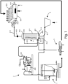
- a plant for the exploitation of the anaerobic digestate leaving a plant for the production of energy from biogas comprises: a biodigester 1, connected to a cogenerator 2, and to which the biodigester 1 sends the biogas produced, said biodigester 1 processing an organic matrix and being further connected to a separator 3 to which the biodigester 1 sends the outgoing digestate.
- Said separator 3 separates the digestate received into liquid fraction and solid fraction and sends them, respectively, to a stripping tower 4 and to a biofiltering bed 5.
- the digestate and/or the solid separate fraction can be treated in advance by mechanical grinding, for example by means of a grinder pump or grinding means included inside said separator 3.
- Said biofiltering bed 5 collects the solid fraction of digestate and allows the solid fraction to be processed in such a way as to obtain a fertiliser enriched with nitrogen and pasteurised, at the outlet from said biofiltering bed 5.
- Said stripping tower 4 comprises a lower portion 401 or bottom 401, an upper portion 402 or head 402, and side walls 413.
- said lower portion 401 receives, by means of a hydraulic connection, the liquid fraction of the digestate from the separator 3, and receives the exhaust fumes directly from the cogenerator 2.
- said lower portion 401 is connected hydraulically with a hopper 6 fro which leaves the processed part of the liquid fraction of digestate as liquid fertiliser 7.
- said lower portion 401 is also connected with the biodigester 1 to which it can send a part of the liquid fraction of processed digestate for feeding the biodigester 1.
- Said cogenerator 2 comprises an internal combustion engine 202, which produces high temperature exhaust fumes, and a telescopic pipe 201 which conveys, in a direct manner, said high temperature exhaust fumes towards said lower portion 401 of the stripping tower 4, and which is able, as required, to uncouple the cogenerator system 2 from the stripping tower 4 when the latter is stopped or undergoing maintenance.
- Said internal combustion engine 202 è preferably located close to the bottom 401 of said stripping tower 4.
- the fumes have an average temperature at the outlet from the internal combustion engine 202 of the cogenerator 2 of between 280°C and 480°C, which reduces during the path inside the telescopic pipe 201, until reaching an average temperature of between 260°C and 460°C at the inlet of the stripping tower 4.
- Said fumes are drawn to the upper portion 402 of the stripping tower 4 by the action of a blower 403 located downstream of said stripping tower 4 with respect to the direction of flow of said exhaust fumes.
- said stripping tower 4 can be put in a slight negative pressure together with all the circuit for connection to the cogenerator 2, in order not to suffocate the internal combustion engine 202 of the cogenerator 2, causing it to switch off.
- the stripping tower 4 comprises a tank 409, positioned in the lower portion 401, where the liquid digestate coming from the separator 3 is collected up to a predetermined threshold value, said tank 409 being fitted with level sensors 414 which control the quantity di digestate collected so that the liquid coming from the separator 3 does not exceed this threshold value.
- Said stripping tower 4 also comprises a pump 404, preferably a grinder pump 404, which, after the filling of the tank 409, sends the liquid fraction of the digestate from the tank 409 towards the spray nozzles 406 located in the upper portion 402 of stripping tower 4. In particular, said liquid fraction is sent towards said spray nozzles 406 through pipes 405.
- Said spray nozzles 406 spray the liquid digestate towards the chutes located inside the stripping tower 4, which allow an increase in the time of contact of the fluid film which flows on a plurality of plates of said stripping tower 4 with the hot fumes of the cogenerator. Flowing on the chutes the digestate will reach the tank 409 to be again sent to the sprays.
- the hydraulic retention time of said liquid fraction inside said stripping tower 4 is a function both of the quantity of heat available and of the process efficiency to be achieved, on the basis of the characteristics of the digestate to be treated.
- the contact between said hot fumes with said liquid fraction, in particular with said liquid fraction in a nebulised form, advantageously allows the NO x to react with the ammonia and the urea contained in said liquid fraction, with consequent reduction of the emissions of NO x into the atmosphere.
- the reaction is particularly efficient since said fumes flow in a counter-current fashion with respect to said nebulised liquid fraction.
- a first portion 411 of the liquid digestate processed in the stripping tower 4, from which has been removed the ammonia is sent towards the hopper 6 from which is collected the liquid fertiliser 7, for example by means of a special valve; a second portion 412 of the digestate processed in the stripping tower 4 can be conveyed towards the biodigester 1.
- said liquid fertiliser 7 has a pH of between 7 and 8, which is advantageously compatible with high quality farming.
- said liquid fertiliser 7 is advantageously compatible with farming which, currently, only allows chemically synthesised or chemical fertilisers, for example intensive farming or fourth range farming production, in which fertilisers containing potential pathogenic germs are not permitted.
- said liquid fertiliser 7 since it has been obtained by reducing the ammonia fraction of said liquid fraction of digestate, advantageously eliminates the risk of dispersion of ammonia into the atmosphere during the use of said fertiliser.
- the stripping tower 4 also comprises, at the upper part of the tank 409, a suitable system of valves for the entrance of ambient air, which is able to guarantee the operation of the system at atmospheric pressure.
- Said pump 404 inside the stripping tower 4 is able to:
- the spray nozzles 406 uniformly diffuse the liquid fraction of digestate on the plates of the tower present in the upper portion 402 of the stripping tower 4 favouring the formation of a fluid film which results in the following phenomena:
- the mechanical treatment of the liquid fraction aimed at reducing the grain size of the solid residue or particulates contained in it allows the heat exchange to be further maximised between liquid fraction and fumes, further favouring the hydrolysis of the lignocellulosic compounds.
- a material is obtained which can be processed inside said biodigester 1.
- the obtaining of the new material, which has new bio-chemical potential, is particularly advantageous, since it is material contained in the digestate which usually remains unused.
- the liquid fraction portion which can be sent to said biodigester 1 is depleted in terms of ammonia, thereby improving the ratio between carbon and nitrogen inside said digester 1.
- the sending of part of the liquid fraction inside said biodigester advantageously allows the recirculation of heat and therefore thermal power inside the plant, optimising in the best way the energy balance of the plant itself.
- Said second portion 412 of digestate processed by the stripping tower 4 reaches the biodigester 1 by means of the same main grinder pump with a suitable system of pneumatic valves which avoid the contact of said second portion 412 with other organic matrices before entry inside the biodigester 1, since the heat contained in the liquid treated could develop the anaerobic bacterial reaction also outside the biodigester 1 with consequent loss of biogas.
- said solid fraction is treated to obtain said solid fertiliser 8 by means of the following process.
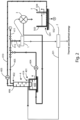
- Said biofiltering bed 5 receives said solid fraction coming from said separator.
- said biofiltering bed 5 is located beneath said separator 3 or beneath said mechanical means for its grinding, and receives a daily flow of solid fraction of digestate of between 10% and 40% of the matrices entering the biodigester 1.
- Said solid fraction can in fact be pre-treated mechanically by grinding in such a way as to have an optimum grain size, preferably between approximately 100 ⁇ m and approximately 5mm.
- said biofiltering bed 5 comprises: a lower portion 501, an upper portion 503, side walls 504 and a movable hatch 505, also called an openable hatch 505.
- Said biofiltering bed 5 is designed to contain the solid material leaving the biodigester for a predetermined number of days to be enriched with ammonia and pasteurised by the insufflating of the mixture of ammonia and vapour transported by the pipe 410 coming from the stripping tower 4 towards perforated pipes 502 which are connected to the blower 403.
- the optimum grain size of said solid fraction guarantees the low permeability of it to said mixture of ammonia and vapour, with consequent long times of residence of the gases, in order to maximise the bio-absorption of the ammonia in the solid.
- the bed of filter material comprising said solid fraction, or biofiltering bed has high values of carbon, designed to maximise the bio-absorption of the ammonium nitrate.
- the temperature of the gas rich in ammonia and water vapour coming from the stripping tower 4 is between 80°C and 150°C, and is lowered by addition of ambient air until reaching a temperature of between 60°C and 90°C, preferably equal to approximately 80°C.
- said stripping tower 4 has at said upper portion 402 a dosing and pressure control valve.
- Said dosing valve provides the correct quantity of oxygen to the hot air at the outlet from said stripping tower, so as to favour said bio-absorption process, and allow the adjustment of the relative temperature, in such a way as to reach said range of temperatures between 60°C and 90°C, preferably between 60°C and 80°C, in order to optimise the biological processes which occur in the biofiltering bed.
- said dosing and pressure control valve is designed to avoid, after a malfunction of the blower 403, that said stripping tower 4 can enter into pressure (or negative pressure).
- the ambient air is also added in order to provide the oxygen to activate and feed the aerobic digestion of the pile of solid digestate falling from the separator 3.
- the aerobic reaction is exothermal and helps to maintain a temperature in the pile of approximately 70°C, which is a temperature at which the enrichment in nitrogen and nutrients and the pasteurisation process of the solid separate occurs.
- the pile of solid digestate broken up falling from the separator has a height of between 1 and 5 metres. In this way, the pile itself constitutes a biofiltering bed rich in carbon, in which the bacteria, by means of the aerobic process, transform the ammonium nitrite into nitric nitrogen allowing the entrapment inside the solid matrix.
- said biofiltering bed dries the vapours arriving from the blower 403.
- the solid separate is insufflated for a period of time varying between 1 and 5 days, at the end of which it is rich with an organic fraction and all the micro and macro elements necessary for the fertilisation, it has been enriched with the excess of nitrogen eliminated from the liquid fraction, it is pasteurised, and it is stabilised thanks to the aerobic reaction forced by the continuous insufflating of oxygen and hot vapours.
- a solid fertiliser is created usually starting from the elements included inside the bio-digestate, without the addition of external chemical additives.
- the openable hatch 505 allows the extraction and the collection of the solid fertiliser 8 (that is to say, nitrogen fertiliser) obtained.
- said biofiltering bed can be renewed in a continuous manner starting from said solid fraction of the bio-digestate, in order to guarantee the maximum efficiency of said bio-absorption process and the removal of the emissions of ammonia into the atmosphere.
- Said fertiliser 8 also has said optimum pH values, that is, pH values between 7 and 8.
- Example 1 250 kW electrical plants
- the fumes produced by the internal combustion engine of the cogenerator contain a quantity of heat substantially equal to 300 kW/h and have an average temperature at the outlet of the engine of approximately 400°C, which reduces along the path towards the stripping tower until reaching an average temperature of 320°C at the inlet of the stripping tower.
- the fumes inside the stripping tower are drawn upwards using a large capacity fan to form a negative pressure inside the towers of just a few mbar and a pressure below the biofiltering bed of 200 mbar
- the stripping tower, all the pipes and the components in contact with the material to be treated are made of stainless steel, in order to withstand the high thermal stresses, the corrosive nature of the material to be treated, which are rich in metals, and the high corrosive power of the engine gases.
- the plant also comprises a screw separator, overlying the biofiltering bed made of concrete 5m x 5m x 5m with a stainless steel side which can be opened for treating the fraction which can be shovelled.
- a hopper may be added to the stripping tower which is able to feed the line for bottling concentrated liquid fertiliser coming from the tower.
- the pump for movement of the liquid must be a grinder pump and be able to work at high operating temperatures of the liquid to be treated (at least 70°C).
- the liquid digestate falls into the tank located in the lower portion of the stripping tower, which is filled up to a volume of 1m 3 .
- the pump draws liquid from the bottom 401 and returns it to the top of the stripping tower for a period of time to ensure the zeroing of the pathogenic bacterial loads as well as continuously moving the bottom 401 to avoid deposits and stagnation.
- the plant also comprises a series of pneumatic valves controlled by a programmable logic controller (PLC) connected to various level and temperature sensors installed in the stripping tower.
- PLC programmable logic controller
- the control system uses the same pump firstly for recycling, then for emptying and then for washing the tower.
- the stripping tower treats at the inlet, daily, approximately 30 m 3 /d of liquid fraction of the digestate coming from the separator.
- the quantity of liquid fertiliser and organic matrix obtained per day coming from the stripping tower is approximately 23.04 m 3 /d.
- the daily quantity coming from the stripping tower towards the biodigester of the fraction for re-use of the digestate treated and rich in cellulose was approximately 10 m 3 /d.
- the time required for loading and unloading the stripping tower is substantially equal to 8 minutes, whilst the time for recirculation of the liquid fraction inside the stripping tower is substantially equal to 32 minutes.
- the separator produced a quantity of solid separate digestate substantially equal to 18m 3 /d and it was loaded with substantially 70 m 3 /d, equal to approximately 70000 kg of digestate per day.
- the solid separate has been accumulated in the biofiltering bed, comprising a container made of concrete and stainless steel located above the separator and able to contain at least 4 days of solid material coming from the biodigester.
- the container is accessible from the outside through the stainless steel door which opens once the cycle has finished and it allows it to be emptied by mechanical means.
- the mixture of ammonia and vapour coming from the stripping tower has been blown in the perforated pipes present on the bottom of the biofiltering bed with a flow rate of approximately 1160 m 3 /h.
- the temperature of the flow of gas which is rich in ammonia and water vapour at the outlet from the stripping tower is equal to 75-80°C, and adding ambient air, maintains the temperature in the pile always greater than 70°C.
- the pile of solid digestate broken up falling from the separator has been kept at a height varying between 1 and 5 m during the 5 days of treatment.
- the solid separate has been treated for the period of operation of the cycle, at the end of which it is rich with an organic fraction and all the micro and macro elements necessary for the fertilisation, it has been enriched with the excess of nitrogen eliminated from the liquid fraction, it is pasteurised, and it is stabilised thanks to the aerobic reaction forced by the continuous insufflating of oxygen and hot vapours. It is then extracted and packaged ready for sale.
- the fertilisers obtained in this way have been tested in greenhouses, obtaining increases in productivity per m2 varying between 30% and 70% depending on the conditions di fertility of the fertilised soil. Moreover, the fertilisers obtained have been able to reconstruct the necessary layer of fertile organic substance where the chemical fertilisation had rendered the greenhouses inert.
- the solid fraction was lastly used with success for growing worms, obtaining high quality fertilisers, rich in humic and fulvic acids which are able to improve, in some cases by even more than 100%, the productivity of the fertilised land.
Landscapes
- Chemical & Material Sciences (AREA)
- Molecular Biology (AREA)
- Life Sciences & Earth Sciences (AREA)
- Health & Medical Sciences (AREA)
- Engineering & Computer Science (AREA)
- Biotechnology (AREA)
- Chemical Kinetics & Catalysis (AREA)
- General Chemical & Material Sciences (AREA)
- Microbiology (AREA)
- Biochemistry (AREA)
- Organic Chemistry (AREA)
- Physical Water Treatments (AREA)
- Fertilizers (AREA)
- Treatment Of Sludge (AREA)
Claims (7)
- Verfahren zur Verwertung von anaeroben Gärresten, die aus Anlagen zur Erzeugung von Energie aus Biogas stammen, wobei die Anlagen zur Erzeugung von Energie aus Biogas einen Biokocher (1), der zur Behandlung einer organischen Matrix und zur Erzeugung von Biogas und Gärresten bestimmt ist, und einen Kogenerator (2) umfassen, der durch das aus dem Biokocher (1) stammende Biogas gespeist wird und zur Erzeugung von Energie und Abgasen bestimmt ist; wobei das Verfahren die folgenden Schritte umfasst:- trennen des aus dem Bioklärer (1) stammenden Gärrestes, um eine flüssige Fraktion, die gegebenenfalls feste Rückstände enthält, und eine feste Fraktion zu erhalten;- gleichzeitig mit und/oder vor und/oder nach dem Trennungsschritt, Zerkleinern des Gärrückstands und/oder der festen Fraktion;- strippen von Ammoniak aus der in dem Trennschritt erhaltenen flüssigen Fraktion mit Hilfe der Abgase, die von dem Kogenerator (2) kommen, um ein an Ammoniak und Wasserdampf reiches Gas und eine sterilisierte und an Ammoniak verarmte flüssige Fraktion zu erhalten, die zur Verwendung als Flüssigdünger bestimmt ist; und- einblasen der in der Trennstufe erhaltenen festen Fraktion mit Hilfe des in der Abstreifstufe erhaltenen Gases, um eine mit Ammoniak angereicherte und pasteurisierte feste Fraktion zu erhalten, wobei das in die feste Fraktion eingeblasene Gas mit Luft vorgemischt wird;wobei das Verfahren dadurch gekennzeichnet ist, dass das in die feste Fraktion eingeblasene und mit Luft vorgemischte Gas eine Temperatur zwischen 60°C und 80°C aufweist.
- Verfahren nach Anspruch 1, dadurch gekennzeichnet, dass es die folgenden Schritte umfasst:- entnahme eines ersten Teils der flüssigen Fraktion, die durch den Schritt des Strippens von Ammoniak abgereichert wurde; und- zuführen eines restlichen Teils der flüssigen Fraktion, die in der Abtrennungsstufe erhalten wurde und an Ammoniak verarmt ist, zu dem Biodigestor (1).
- Verfahren nach einem der vorhergehenden Ansprüche, dadurch gekennzeichnet, dass die flüssige Fraktion feste Rückstände enthält und der Schritt zum Strippen von Ammoniak die folgenden Teilschritte umfasst:- zerkleinern der festen Rückstände der flüssigen Fraktion unter Verwendung von Zerkleinerungsmitteln (404);- zerstäuben der flüssigen Fraktion, die zerkleinerte feste Rückstände enthält; und- strömenlassen der vernebelten flüssigen Fraktion im Gegenstrom zu den Abgasen.
- Verfahren nach Anspruch 3, dadurch gekennzeichnet, dass die Teilschritte des Strippens wiederholt werden.
- Verfahren nach einem der vorhergehenden Ansprüche, dadurch gekennzeichnet, dass die während des Strippschrittes verwendeten Gase eine Temperatur zwischen 260°C und 460°C, vorzugsweise gleich etwa 320°C, aufweisen.
- Verfahren nach einem der vorangehenden Ansprüche, dadurch gekennzeichnet, dass das in die feste Fraktion eingeblasene Gas eine Temperatur zwischen 75°C und 80°C hat.
- Verfahren nach einem der vorhergehenden Ansprüche, dadurch gekennzeichnet, dass der Strippschritt ohne Verwendung von pH-Korrekturmitteln erfolgt.
Applications Claiming Priority (1)
| Application Number | Priority Date | Filing Date | Title |
|---|---|---|---|
| IT102018000005357A IT201800005357A1 (it) | 2018-05-14 | 2018-05-14 | Processo e impianto per la valorizzazione del digestato anaerobico in uscita dagli impianti di produzione di energia da biogas volto alla produzione di bio-concimi e nuovo substrato biodisponibile. |
Publications (3)
| Publication Number | Publication Date |
|---|---|
| EP3569586A1 EP3569586A1 (de) | 2019-11-20 |
| EP3569586B1 true EP3569586B1 (de) | 2025-02-12 |
| EP3569586C0 EP3569586C0 (de) | 2025-02-12 |
Family
ID=63080333
Family Applications (1)
| Application Number | Title | Priority Date | Filing Date |
|---|---|---|---|
| EP19174354.1A Active EP3569586B1 (de) | 2018-05-14 | 2019-05-14 | Verfahren zur umsetzung von anaerobem digestat aus biogaskraftwerken in bio-düngemittel und substrat |
Country Status (2)
| Country | Link |
|---|---|
| EP (1) | EP3569586B1 (de) |
| IT (1) | IT201800005357A1 (de) |
Families Citing this family (2)
| Publication number | Priority date | Publication date | Assignee | Title |
|---|---|---|---|---|
| EP4471120A1 (de) * | 2023-06-01 | 2024-12-04 | Kanadevia Inova AG | Biogaserzeugungssystem und betriebssteuerungsverfahren |
| WO2024246243A1 (en) * | 2023-06-01 | 2024-12-05 | Kanadevia Inova Ag | Method and system for the hygienization of a digestate in the production of biogas |
Family Cites Families (4)
| Publication number | Priority date | Publication date | Assignee | Title |
|---|---|---|---|---|
| US6299774B1 (en) * | 2000-06-26 | 2001-10-09 | Jack L. Ainsworth | Anaerobic digester system |
| CA2416690C (en) * | 2003-01-20 | 2008-08-12 | Alberta Research Council Inc. | Process for removal and recovery of nutrients from digested manure or other organic wastes |
| AT509318B8 (de) * | 2010-05-03 | 2011-09-15 | Rudolf Grossfurtner Gmbh | Abtrennverfahren |
| BR112013007682A2 (pt) * | 2010-09-29 | 2016-08-09 | Himark Biogas Inc | método de recuperação de nutrientes e usos do mesmo |
-
2018
- 2018-05-14 IT IT102018000005357A patent/IT201800005357A1/it unknown
-
2019
- 2019-05-14 EP EP19174354.1A patent/EP3569586B1/de active Active
Also Published As
| Publication number | Publication date |
|---|---|
| IT201800005357A1 (it) | 2019-11-14 |
| EP3569586A1 (de) | 2019-11-20 |
| EP3569586C0 (de) | 2025-02-12 |
Similar Documents
| Publication | Publication Date | Title |
|---|---|---|
| US10239776B2 (en) | Organics and nutrient recovery from anaerobic digester residues | |
| EP2675770B1 (de) | Gewinnung von organischen stoffen und nährstoffen aus anaeroben faulanlagerückständen | |
| KR20090053020A (ko) | 축분의 유기질 비료화 제조방법 | |
| KR101807632B1 (ko) | 배출가스 순환형 고효율 축분 퇴비화장치 및 이를 이용한 고효율 축분 퇴비화방법 | |
| CN101637778A (zh) | 一种有机废弃物综合处理工艺 | |
| EP3569586B1 (de) | Verfahren zur umsetzung von anaerobem digestat aus biogaskraftwerken in bio-düngemittel und substrat | |
| CN115286091A (zh) | 处理有机废物的可控湿式催化氧化推流式管式反应系统 | |
| CN106116734A (zh) | 有机固体废弃物的好氧堆肥装置和好氧堆肥方法 | |
| CN116157363A (zh) | 处理有机废物的方法和装置,包括其厌氧消化和消化物的堆肥 | |
| JP4527610B2 (ja) | 生ゴミ等の肥料化方法及び肥料化装置 | |
| KR101595184B1 (ko) | 유기성 폐기물의 퇴비화방법 | |
| KR101183744B1 (ko) | 원통형 또는 다각형 밀폐형 발효조에 축사 깔짚을 포함한 축사폐기물을 수분조절제로 가축분뇨 폐수 무 방류, 속성발효로 퇴, 액비를 제조하는 방법과 장치. | |
| KR100723066B1 (ko) | 가축분뇨 비료화 방법 및 그 장치 | |
| RU2399184C1 (ru) | Биогазовый комплекс | |
| KR20060111419A (ko) | 유기물을 함유한 폐기물 및 배설물을 자원화 하는 방법과장치 | |
| CN110104898A (zh) | 一种垃圾厌氧、好氧堆肥、废水净化的处理系统 | |
| CN205774176U (zh) | 一种有机固体废弃物的好氧堆肥装置 | |
| CN111153715A (zh) | 亚临界水技术处理畜禽粪污的设备及工艺 | |
| CN112898056A (zh) | 一种城市生活污泥资源化利用的先进技术 | |
| CN112358350A (zh) | 一种养殖废弃物无害处理方法 | |
| CN222744203U (zh) | 一种畜禽粪污资源化处理系统 | |
| CN216460815U (zh) | 水热腐殖化工业反应系统 | |
| DE102011012285B4 (de) | Hybrid Fermentation | |
| EP2977440A1 (de) | Verfahren und system zur wiederverwertung in der landwirtschaft von nährstoffen aus der nahrungskette | |
| Gayfullin et al. | Results of experimental studies of a small-volume biogas plant |
Legal Events
| Date | Code | Title | Description |
|---|---|---|---|
| PUAI | Public reference made under article 153(3) epc to a published international application that has entered the european phase |
Free format text: ORIGINAL CODE: 0009012 |
|
| STAA | Information on the status of an ep patent application or granted ep patent |
Free format text: STATUS: THE APPLICATION HAS BEEN PUBLISHED |
|
| AK | Designated contracting states |
Kind code of ref document: A1 Designated state(s): AL AT BE BG CH CY CZ DE DK EE ES FI FR GB GR HR HU IE IS IT LI LT LU LV MC MK MT NL NO PL PT RO RS SE SI SK SM TR |
|
| AX | Request for extension of the european patent |
Extension state: BA ME |
|
| STAA | Information on the status of an ep patent application or granted ep patent |
Free format text: STATUS: REQUEST FOR EXAMINATION WAS MADE |
|
| 17P | Request for examination filed |
Effective date: 20200520 |
|
| RBV | Designated contracting states (corrected) |
Designated state(s): AL AT BE BG CH CY CZ DE DK EE ES FI FR GB GR HR HU IE IS IT LI LT LU LV MC MK MT NL NO PL PT RO RS SE SI SK SM TR |
|
| RIN1 | Information on inventor provided before grant (corrected) |
Inventor name: CATTANEO, GIANCARLO Inventor name: FRUNZO, LUIGI |
|
| STAA | Information on the status of an ep patent application or granted ep patent |
Free format text: STATUS: EXAMINATION IS IN PROGRESS |
|
| 17Q | First examination report despatched |
Effective date: 20221107 |
|
| GRAP | Despatch of communication of intention to grant a patent |
Free format text: ORIGINAL CODE: EPIDOSNIGR1 |
|
| STAA | Information on the status of an ep patent application or granted ep patent |
Free format text: STATUS: GRANT OF PATENT IS INTENDED |
|
| RIC1 | Information provided on ipc code assigned before grant |
Ipc: C05F 17/40 20200101ALI20240925BHEP Ipc: C05F 17/50 20200101ALI20240925BHEP Ipc: C05F 17/00 20060101AFI20240925BHEP |
|
| INTG | Intention to grant announced |
Effective date: 20241028 |
|
| GRAS | Grant fee paid |
Free format text: ORIGINAL CODE: EPIDOSNIGR3 |
|
| GRAA | (expected) grant |
Free format text: ORIGINAL CODE: 0009210 |
|
| STAA | Information on the status of an ep patent application or granted ep patent |
Free format text: STATUS: THE PATENT HAS BEEN GRANTED |
|
| RIN1 | Information on inventor provided before grant (corrected) |
Inventor name: FRUNZO, LUIGI Inventor name: CATTANEO, GIANCARLO |
|
| AK | Designated contracting states |
Kind code of ref document: B1 Designated state(s): AL AT BE BG CH CY CZ DE DK EE ES FI FR GB GR HR HU IE IS IT LI LT LU LV MC MK MT NL NO PL PT RO RS SE SI SK SM TR |
|
| REG | Reference to a national code |
Ref country code: GB Ref legal event code: FG4D |
|
| REG | Reference to a national code |
Ref country code: CH Ref legal event code: EP |
|
| REG | Reference to a national code |
Ref country code: DE Ref legal event code: R096 Ref document number: 602019065687 Country of ref document: DE |
|
| REG | Reference to a national code |
Ref country code: IE Ref legal event code: FG4D |
|
| U01 | Request for unitary effect filed |
Effective date: 20250305 |
|
| U07 | Unitary effect registered |
Designated state(s): AT BE BG DE DK EE FI FR IT LT LU LV MT NL PT RO SE SI Effective date: 20250312 |
|
| U20 | Renewal fee for the european patent with unitary effect paid |
Year of fee payment: 7 Effective date: 20250328 |
|
| PG25 | Lapsed in a contracting state [announced via postgrant information from national office to epo] |
Ref country code: RS Free format text: LAPSE BECAUSE OF FAILURE TO SUBMIT A TRANSLATION OF THE DESCRIPTION OR TO PAY THE FEE WITHIN THE PRESCRIBED TIME-LIMIT Effective date: 20250512 |
|
| PG25 | Lapsed in a contracting state [announced via postgrant information from national office to epo] |
Ref country code: PL Free format text: LAPSE BECAUSE OF FAILURE TO SUBMIT A TRANSLATION OF THE DESCRIPTION OR TO PAY THE FEE WITHIN THE PRESCRIBED TIME-LIMIT Effective date: 20250212 |
|
| PG25 | Lapsed in a contracting state [announced via postgrant information from national office to epo] |
Ref country code: ES Free format text: LAPSE BECAUSE OF FAILURE TO SUBMIT A TRANSLATION OF THE DESCRIPTION OR TO PAY THE FEE WITHIN THE PRESCRIBED TIME-LIMIT Effective date: 20250212 |
|
| PG25 | Lapsed in a contracting state [announced via postgrant information from national office to epo] |
Ref country code: NO Free format text: LAPSE BECAUSE OF FAILURE TO SUBMIT A TRANSLATION OF THE DESCRIPTION OR TO PAY THE FEE WITHIN THE PRESCRIBED TIME-LIMIT Effective date: 20250512 Ref country code: IS Free format text: LAPSE BECAUSE OF FAILURE TO SUBMIT A TRANSLATION OF THE DESCRIPTION OR TO PAY THE FEE WITHIN THE PRESCRIBED TIME-LIMIT Effective date: 20250612 |
|
| PG25 | Lapsed in a contracting state [announced via postgrant information from national office to epo] |
Ref country code: HR Free format text: LAPSE BECAUSE OF FAILURE TO SUBMIT A TRANSLATION OF THE DESCRIPTION OR TO PAY THE FEE WITHIN THE PRESCRIBED TIME-LIMIT Effective date: 20250212 |
|
| PG25 | Lapsed in a contracting state [announced via postgrant information from national office to epo] |
Ref country code: GR Free format text: LAPSE BECAUSE OF FAILURE TO SUBMIT A TRANSLATION OF THE DESCRIPTION OR TO PAY THE FEE WITHIN THE PRESCRIBED TIME-LIMIT Effective date: 20250513 |
|
| PG25 | Lapsed in a contracting state [announced via postgrant information from national office to epo] |
Ref country code: SM Free format text: LAPSE BECAUSE OF FAILURE TO SUBMIT A TRANSLATION OF THE DESCRIPTION OR TO PAY THE FEE WITHIN THE PRESCRIBED TIME-LIMIT Effective date: 20250212 |
|
| PG25 | Lapsed in a contracting state [announced via postgrant information from national office to epo] |
Ref country code: CZ Free format text: LAPSE BECAUSE OF FAILURE TO SUBMIT A TRANSLATION OF THE DESCRIPTION OR TO PAY THE FEE WITHIN THE PRESCRIBED TIME-LIMIT Effective date: 20250212 |
|
| PG25 | Lapsed in a contracting state [announced via postgrant information from national office to epo] |
Ref country code: SK Free format text: LAPSE BECAUSE OF FAILURE TO SUBMIT A TRANSLATION OF THE DESCRIPTION OR TO PAY THE FEE WITHIN THE PRESCRIBED TIME-LIMIT Effective date: 20250212 |
|
| PLBE | No opposition filed within time limit |
Free format text: ORIGINAL CODE: 0009261 |
|
| STAA | Information on the status of an ep patent application or granted ep patent |
Free format text: STATUS: NO OPPOSITION FILED WITHIN TIME LIMIT |
|
| REG | Reference to a national code |
Ref country code: CH Ref legal event code: H13 Free format text: ST27 STATUS EVENT CODE: U-0-0-H10-H13 (AS PROVIDED BY THE NATIONAL OFFICE) Effective date: 20251223 |
|
| REG | Reference to a national code |
Ref country code: CH Ref legal event code: L10 Free format text: ST27 STATUS EVENT CODE: U-0-0-L10-L00 (AS PROVIDED BY THE NATIONAL OFFICE) Effective date: 20251224 |
|
| PG25 | Lapsed in a contracting state [announced via postgrant information from national office to epo] |
Ref country code: CH Free format text: LAPSE BECAUSE OF NON-PAYMENT OF DUE FEES Effective date: 20250531 |
|
| 26N | No opposition filed |
Effective date: 20251113 |
|
| GBPC | Gb: european patent ceased through non-payment of renewal fee |
Effective date: 20250514 |
|
| PG25 | Lapsed in a contracting state [announced via postgrant information from national office to epo] |
Ref country code: MC Free format text: LAPSE BECAUSE OF FAILURE TO SUBMIT A TRANSLATION OF THE DESCRIPTION OR TO PAY THE FEE WITHIN THE PRESCRIBED TIME-LIMIT Effective date: 20250212 |
|
| U20 | Renewal fee for the european patent with unitary effect paid |
Year of fee payment: 8 Effective date: 20260303 |
|
| PG25 | Lapsed in a contracting state [announced via postgrant information from national office to epo] |
Ref country code: GB Free format text: LAPSE BECAUSE OF NON-PAYMENT OF DUE FEES Effective date: 20250514 |
|
| PG25 | Lapsed in a contracting state [announced via postgrant information from national office to epo] |
Ref country code: IE Free format text: LAPSE BECAUSE OF NON-PAYMENT OF DUE FEES Effective date: 20250514 |