EP3569443B1 - Fahrzeugsitz mit einer federeinrichtung - Google Patents
Fahrzeugsitz mit einer federeinrichtung Download PDFInfo
- Publication number
- EP3569443B1 EP3569443B1 EP19174147.9A EP19174147A EP3569443B1 EP 3569443 B1 EP3569443 B1 EP 3569443B1 EP 19174147 A EP19174147 A EP 19174147A EP 3569443 B1 EP3569443 B1 EP 3569443B1
- Authority
- EP
- European Patent Office
- Prior art keywords
- vehicle seat
- pivot axis
- spring rod
- rocker
- connecting part
- Prior art date
- Legal status (The legal status is an assumption and is not a legal conclusion. Google has not performed a legal analysis and makes no representation as to the accuracy of the status listed.)
- Active
Links
Images



Classifications
-
- B—PERFORMING OPERATIONS; TRANSPORTING
- B60—VEHICLES IN GENERAL
- B60N—SEATS SPECIALLY ADAPTED FOR VEHICLES; VEHICLE PASSENGER ACCOMMODATION NOT OTHERWISE PROVIDED FOR
- B60N2/00—Seats specially adapted for vehicles; Arrangement or mounting of seats in vehicles
- B60N2/24—Seats specially adapted for vehicles; Arrangement or mounting of seats in vehicles for particular purposes or particular vehicles
- B60N2/38—Seats specially adapted for vehicles; Arrangement or mounting of seats in vehicles for particular purposes or particular vehicles specially constructed for use on tractors or like off-road vehicles
- B60N2/39—Seats tiltable to compensate for roll inclination of vehicles
-
- B—PERFORMING OPERATIONS; TRANSPORTING
- B60—VEHICLES IN GENERAL
- B60N—SEATS SPECIALLY ADAPTED FOR VEHICLES; VEHICLE PASSENGER ACCOMMODATION NOT OTHERWISE PROVIDED FOR
- B60N2/00—Seats specially adapted for vehicles; Arrangement or mounting of seats in vehicles
- B60N2/50—Seat suspension devices
- B60N2/502—Seat suspension devices attached to the base of the seat
-
- B—PERFORMING OPERATIONS; TRANSPORTING
- B60—VEHICLES IN GENERAL
- B60N—SEATS SPECIALLY ADAPTED FOR VEHICLES; VEHICLE PASSENGER ACCOMMODATION NOT OTHERWISE PROVIDED FOR
- B60N2/00—Seats specially adapted for vehicles; Arrangement or mounting of seats in vehicles
- B60N2/50—Seat suspension devices
- B60N2/54—Seat suspension devices using mechanical springs
-
- B—PERFORMING OPERATIONS; TRANSPORTING
- B60—VEHICLES IN GENERAL
- B60N—SEATS SPECIALLY ADAPTED FOR VEHICLES; VEHICLE PASSENGER ACCOMMODATION NOT OTHERWISE PROVIDED FOR
- B60N2/00—Seats specially adapted for vehicles; Arrangement or mounting of seats in vehicles
- B60N2/50—Seat suspension devices
- B60N2/54—Seat suspension devices using mechanical springs
- B60N2/546—Leaf- or flexion springs
-
- B—PERFORMING OPERATIONS; TRANSPORTING
- B60—VEHICLES IN GENERAL
- B60N—SEATS SPECIALLY ADAPTED FOR VEHICLES; VEHICLE PASSENGER ACCOMMODATION NOT OTHERWISE PROVIDED FOR
- B60N2/00—Seats specially adapted for vehicles; Arrangement or mounting of seats in vehicles
- B60N2/02—Seats specially adapted for vehicles; Arrangement or mounting of seats in vehicles the seat or part thereof being movable, e.g. adjustable
- B60N2002/0204—Seats specially adapted for vehicles; Arrangement or mounting of seats in vehicles the seat or part thereof being movable, e.g. adjustable characterised by the seat or seat part turning about or moving along a non-standard, particular axis, i.e. an axis different from the axis characterising the conventional movement
- B60N2002/0212—Seats specially adapted for vehicles; Arrangement or mounting of seats in vehicles the seat or part thereof being movable, e.g. adjustable characterised by the seat or seat part turning about or moving along a non-standard, particular axis, i.e. an axis different from the axis characterising the conventional movement the seat or seat part turning about or moving along a longitudinal axis
-
- B—PERFORMING OPERATIONS; TRANSPORTING
- B60—VEHICLES IN GENERAL
- B60N—SEATS SPECIALLY ADAPTED FOR VEHICLES; VEHICLE PASSENGER ACCOMMODATION NOT OTHERWISE PROVIDED FOR
- B60N2/00—Seats specially adapted for vehicles; Arrangement or mounting of seats in vehicles
- B60N2/02—Seats specially adapted for vehicles; Arrangement or mounting of seats in vehicles the seat or part thereof being movable, e.g. adjustable
- B60N2002/0204—Seats specially adapted for vehicles; Arrangement or mounting of seats in vehicles the seat or part thereof being movable, e.g. adjustable characterised by the seat or seat part turning about or moving along a non-standard, particular axis, i.e. an axis different from the axis characterising the conventional movement
- B60N2002/0216—Seats specially adapted for vehicles; Arrangement or mounting of seats in vehicles the seat or part thereof being movable, e.g. adjustable characterised by the seat or seat part turning about or moving along a non-standard, particular axis, i.e. an axis different from the axis characterising the conventional movement the seat or seat part turning about or moving along a transversal axis
Definitions
- the invention relates to a vehicle seat with a spring device for springing pivoting movements of an upper part of the vehicle seat with respect to a lower part of the vehicle seat about a pivot axis extending in a vehicle seat longitudinal direction or vehicle seat width direction.
- Such vehicle seats are known from the prior art, for example from WO 2014/176130 A1 .
- a vehicle seat can be seen which can be pivoted about a pivot axis and is mounted with respect to the body by means of spring or damping devices.
- the arrangement of the suspension or damping is very space-consuming.
- the core idea of the invention is to provide a vehicle seat with a spring device for springing pivoting movements of an upper part of the vehicle seat relative to a lower part of the vehicle seat about a pivot axis extending in a vehicle seat longitudinal direction or vehicle seat width direction, with a first spring rod elastically deformable in the transverse direction and the pivot axis preferably in a common level are arranged, and a connecting part pivotable about the pivot axis connects the first spring rod and the pivot axis in order to deform the first spring rod when the upper part is pivoted.
- the first spring rod and the connecting part are part of the spring device.
- the common plane in which the pivot axis and the first spring bar can be arranged is the plane that is formed by the longitudinal direction of the vehicle seat and a width direction of the vehicle seat.
- a spring bar is to be understood here as a bar which has resilient properties and, in particular, is elastically deformable in its transverse direction.
- the spring rod When the rod is loaded, caused by the elastic deformation, the spring rod is deformed for a limited period of time, as a result of which return forces are generated which return the spring rod to its initial state when the load is removed.
- Alternative formulations to the transverse direction can also be understood to mean the formulations “direction transverse to a longitudinal axis of the spring rod” or “radial direction of the spring rod”.
- the connecting part is designed and provided to connect the first spring bar and the pivot axis to one another.
- the connecting part is particularly preferably in operative connection with the upper part, that is to say that when the upper part is pivoted relative to the lower part, the connecting part is also pivoted about the pivot axis. Because the connecting part connects the pivot axis and the first spring bar, the first spring bar is deformed or deformed when the upper part is pivoted and the connecting part is pivoted about the pivot axis, and the upper part is accordingly resilient.
- the first spring rod, the connecting unit and the pivot axis are furthermore preferably arranged between the upper part and the lower part, viewed in a vehicle seat height direction. This enables a further reduction in space.
- the pivot axis is preferably designed as a bearing axis and the pivot axis has a first end and a second end, the first end and the second end of the bearing axis not being rotatably connected to the lower suspension part.
- pivot axis is designed as a bearing shaft, that is, in particular, is rotatably mounted in a plane.
- a first bearing block and a second bearing block are provided, which are each rigidly connected to the lower part and the first bearing block supports the first end of the pivot axis and the second bearing block rotatably or non-rotatably supports the second end of the pivot axis, depending on whether the pivot axis is Bearing axis or is designed as a bearing shaft.
- the first spring rod has a first end and a second end, the first end of the first spring rod and the second end of the spring rod being connected to the lower suspension part, in particular being rigidly connected. This means that a significantly higher rigidity can be achieved. A rigid connection also prevents undesired rotary movements of the first spring rod from occurring when the first spring rod is deformed and this can lead to undesirable effects with regard to the spring properties.
- first end of the first spring bar is connected to the first bearing block and the second end of the first spring bar is connected to the second bearing block.
- connection part is connected to the pivot axis in such a way that when the pivot axis is rotated, the connection part can be displaced along the pivot axis.
- the pivot axis or the bearing shaft is designed as a rotary spindle and the connecting part is designed correspondingly complementary.
- the connecting part is displaced along the rotary spindle, in particular displaced in a translatory manner.
- the connecting part can be displaced in the direction of the pivot axis by applying a train or pressure, for example by using appropriate pneumatic cylinders, Bowden cables, or the like.
- the connecting part can therefore also be referred to as a trolley.
- the suspension properties of the spring device can be changed by adapting the position of the connecting part on the pivot axis.
- the spring device has a second spring bar which is elastically deformable in the transverse direction and which has a first end and a second end, the first end of the second spring bar and the second end of the second spring bar being connected to the lower spring part and the connecting part connects the second spring rod and the pivot axis.
- the statements relating to the first spring bar can also apply to the second spring bar.
- the second spring bar is also in the common plane.
- the suspension properties of the spring device can be set even better.
- the spring rate of the spring device also changes.
- first end of the first spring rod and the first end of the second spring rod have a first distance from one another and the second end of the first spring rod and the second end of the second spring rod have a second distance from one another, the first distance being smaller than the second distance.
- At least one spring bar is arranged at an angle to the pivot axis.
- the first spring bar and the second spring bar are each arranged at an angle to the pivot axis; in particular, the first and the second spring bar can be arranged symmetrically to the pivot axis.
- the connecting part has a first passage and optionally a second passage through which the first spring rod and optionally the second spring rod run.
- the spring device When driving over very uneven terrain, the spring device is exposed to strong alternating loads. It may well be that the passages of the connecting part deflect over time and there is undesirable play in the suspension.
- the ends of the spring bars are arranged at different distances from one another, so the spring bars run wedge-shaped to one another but the passage spacing in the connecting part is constant, the spring bars run essentially parallel up to the connecting part and not parallel after the connecting part. As a result, the spring bars exert a lateral force on the passages of the connecting part, so that any play that occurs is not noticeable.
- the connecting part has a rocker-like structure, a first rocker element being arranged at a first end of the rocker-like structure and a second rocker element being arranged at the second end of the rocker-like structure, at least the first rocker element and the second rocker element with the upper part are in operative contact.
- This rocker-like configuration of the connecting part allows the connecting part to follow the pivoting movement particularly well.
- the connecting part with a rocker-like structure has a rocker point which, viewed in the vertical direction, is arranged perpendicularly below the pivot axis and is in operative connection with the lower part. Due to the rocker point, which is in operative connection with the lower part, the connecting part is accordingly in operative contact with both the upper part and the lower part, whereby the connecting part can follow the pivoting movement of the upper part relative to the lower part particularly well.
- first rocker element and the second rocker element each have a first area, which is trapezoidal in cross section, and a second area, which is rectangular in cross section.
- the first area is advantageously arranged below the second area, viewed in the height direction.
- An end stop of the connecting part is defined by the trapezoidal design, in that when the connecting part is pivoted about the pivot axis so far that a side which has the rocker point as the corner point is connected to the lower part.
- the sides of the trapezoid which run parallel to one another preferably run in the vertical direction.
- the vehicle seat comprises a horizontal suspension, with the horizontal suspension below the spring device viewed in the height direction is arranged.
- the horizontal suspension can be a horizontal suspension which acts in the longitudinal direction of the vehicle seat or in the width direction of the vehicle seat.
- the vehicle seat has a damping device with at least one damper, which is pivotably connected with a first end to the lower part and with a second end to the upper part.
- a first lever element is provided, which is pivotably connected to the lower part with a first end and pivotably connected to the second end of the damper with a second end, and a second lever element is provided which is pivotably connected to the first lever element.
- damping force acting on the upper part can be influenced by the geometry of the lever elements.
- the coupling gear consisting of the first and second lever element enables the damper properties to be adapted as required.
- a vehicle seat 1 according to the invention can be seen which is mounted in a cabin of a vehicle 33.
- the vehicle 33 and, accordingly, the vehicle seat 1 are in a normal operating state 34, that is, the vehicle 33 and the vehicle seat 1 are not deflected.
- the vehicle seat 1 of the Figure 1A can be seen, the vehicle 33 or the vehicle seat 1 being in a deflected operating state 35 here.
- the vehicle 33 is only deflected on one side, in the present case the right side.
- the Figure 2A shows a suspension device 2 according to the invention of a vehicle seat 1 according to a preferred embodiment in a top view.
- a connecting part 8 which has a first passage 36 and a second passage 37, a first spring rod 6 extending through the first passage 36 and a second spring rod 14 extending through the second passage 37.
- the passages 36, 37 here extend in a vehicle seat longitudinal direction L.
- a third passage 40 can also be seen through which the pivot axis 5 extends, the pivot axis 5 being in operative connection with the connecting part 8. It is also conceivable that the passages 36, 37 are arranged to run in the vehicle seat width direction B.
- the connecting part 8 is furthermore with a rocker-like structure 21 comprising a first rocker element 19 and a second rocker element 20, which are connected to one another by a central element 41.
- the middle element 41 has passages 36, 37, 40.
- the suspension device 2 also has a rotary knob 39 which is connected to the pivot axis 5.
- the pivot axis 5 By operating the rotary knob 39, that is to say by turning the rotary knob, the pivot axis 5 is also rotated about its own axis.
- the connecting part 8 By rotating the pivot axis 5, the connecting part 8 is displaced backwards or forwards in the longitudinal direction L of the vehicle seat, whereby the spring properties of the spring device 2 can be adjusted.
- a first stop element 38 and a second stop element 42 are provided, which limit the displacement of the connecting part 8 in the vehicle seat longitudinal direction L or vehicle seat width direction B.
- the first stop element 38 is arranged such that the connecting element 8 is positioned in a central position when it reaches the first stop element 38, that is to say that the connecting part 8 is symmetrical to the center of the upper part 3, the center in the longitudinal direction L of the vehicle seat being meant.
- a damping device 27 is also shown in FIG Figure 2A can be seen, with a damper 30, several dampers 30 being provided here.
- FIG. 11 shows a front view of FIG Figure 2A .
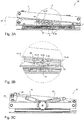
- FIG. 2B A cross-section through the connecting part 8 is shown, and the connecting part 8 has a rocker-like structure 21, with a first end 22 and a second end 23.
- a first rocker element 19 is located at the first end 22 of the structure 21 and at the second end 23 a second rocker element 20 is arranged in the structure.
- Each rocker element 19, 20 has a trapezoidal area 24 and a rectangular area 25, this configuration (trapezoid, rectangle) relating to the cross section shown.
- the rectangular area 25 is arranged above the trapezoidal area 24, viewed in the vehicle seat height direction H, and is in operative contact with the upper part 3.
- the middle element 41 has the first passage 36, the second passage 37 and the third passage 40, the first spring rod 6 passing through the first passage 36, the second spring rod 14 passing through the second passage and the pivot axis 5 passing through the third passage 40 extends.
- the middle element also comprises a rocker point 43, by means of which the connecting part 8 is operatively connected to the lower part 4.
- the central element 41 is not in operative contact with the upper part 3, but only the first rocker element 19 and the second rocker element 20, in particular the rectangular area 25.
- the rectangular area 25 can be made of different materials, for example from a material with poor suspension and damping properties.
- the material is particularly preferably a slidable material.
- the Figure 2D shows a front view of the spring device 2, wherein a damping device is provided with a first damper 30 with a first end 31 and a second end 32, the first end 31 being pivotably connected to the lower part 4 by means of a first pivot axis 44 and the second end 32 is connected to a first lever element 28, the first lever element 28 being pivotably connected to the lower part 4 by means of a second pivot axis 45 and a second lever element 29 being provided which is pivotable by means of a third pivot axis 46 with the first lever element 28 and pivotable by means of a fourth pivot axis 47 is connected to the upper part 3.
- a damping device is provided with a first damper 30 with a first end 31 and a second end 32, the first end 31 being pivotably connected to the lower part 4 by means of a first pivot axis 44 and the second end 32 is connected to a first lever element 28, the first lever element 28 being pivotably connected to the lower part 4 by means of a second pivot axis 45 and a second lever
- the Figure 3A shows the spring device 2 in a deflected operating state 35, that is to say that the upper part 3 performs a pivoting movement with respect to the lower part 4. Since here the connecting part 8 is in operative contact on the one hand with the upper part 3, the connecting part 8 is also pivoted about the pivot axis 5. This has the consequence that the passages 36, 37 are also pivoted about the pivot axis 5 and consequently also the first spring rod 6 and the second spring rod 14; sometimes the spring bars 6, 14 are elastically deformed. Likewise, the connecting part 8 is in operative contact with the lower part 4 by means of the rocker point 43, so that the connecting part 8 is pivoted about this rocker point 43.
- the upper part 3 and the lower part 4 were arranged essentially parallel to one another in the normal operating state 34, the upper part 3 and the lower part 4 now enclose an angle 49 in the deflected operating state 35 and the first spring bar 6 and the second spring bar 14 are now around one The value of a deflection 48 in the vehicle seat height direction H shifted to one another.
- the Figure 3B shows an enlargement of the area B of FIG Figure 3A .
- the pivot axis 5 is not changed in its position or location by the pivoting movement.
- a side 50 of the trapezoidal area 24 of the first rocker element 19 can also be seen, which includes the rocker point 43 and which can function as a limitation of the pivoting movement of the upper part 3. If the side 50 is in contact with the lower part 4, further pivoting of the upper part 3 relative to the lower part 4 in this direction is no longer possible. The same naturally applies to the further trapezoidal area 24 of the second rocker element 20.
- the Figure 3C shows just like the Figure 2D a front view of the spring device 2, but in the deflected operating state 35.
- the Figure 3C the movement of the first lever element 28 and the second lever element 29 can be seen particularly well.
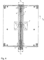
- the Figure 4 shows a particularly preferred embodiment of the spring device 2, the first end 12 of the first spring rod 6 and the first end 15 of the second spring rod 14 at a first distance 17 and the second end 13 of the first spring rod 6 and the second end 16 of the second spring rod 14 are arranged at a second distance 18 from one another.
- the respective distance 17, 18 is measured in the vehicle seat width direction B or the vehicle seat longitudinal direction L.
- the respective distance 17, 18 from the most distant points of the spring bars 6, 14 measured.
- the first distance 17 is smaller than the second distance 18, that is to say in particular that the spring bars 6, 14 do not run parallel to one another, but at an angle to one another.
- the Figures 5A and 5B show the connecting part 8 in the central position 51 and in a displaced position 52, the displaced position 52 being shown in dotted lines.
- the Figure 5A Fig. 3 is a perspective view showing Figure 5B a top view.
- the central position 51 and the displaced position 52 are the maximum positions of the connecting part 8, that is to say that the connecting part 8 can only assume positions between the central position 51 and the displaced position 52, in particular continuously.
- the displacement of the connecting part 8 is limited by a first stop element 38 and a second stop element 42.
Landscapes
- Engineering & Computer Science (AREA)
- Aviation & Aerospace Engineering (AREA)
- Transportation (AREA)
- Mechanical Engineering (AREA)
- Seats For Vehicles (AREA)
- Fluid-Damping Devices (AREA)
- Vehicle Body Suspensions (AREA)
Description
- Die Erfindung betrifft einen Fahrzeugsitz mit einer Federeinrichtung zum Federn von Schwenkbewegungen eines Oberteils des Fahrzeugsitzes gegenüber einem Unterteil des Fahrzeugsitzes um eine in einer Fahrzeugsitzlängsrichtung oder Fahrzeugsitzbreitenrichtung verlaufend angeordneten Schwenkachse.
- Derartige Fahrzeugsitze sind aus dem Stand der Technik bekannt, beispielsweise aus
WO 2014/176130 A1 . Hierbei ist ein Fahrzeugsitz erkennbar, welcher um eine Schwenkachse verschwenkbar ist und mittels Feder- bzw. Dämpfungseinrichtungen gegenüber der Karosserie gefedert bzw. gedämpft gelagert ist. Die Anordnung der Federung bzw. Dämpfung ist allerdings sehr platzintensiv. - Es ist demzufolge Aufgabe der vorliegenden Erfindung, die Nachteile des Standes der Technik zu überkommen und einen Fahrzeugsitz zu präsentieren, welcher eine platzsparende sowie konstruktiv und funktional verbesserte Federung gegenüber dem Stand der Technik aufweist.
- Diese Aufgabe wird gemäß den Merkmalen des Patentanspruches 1 gelöst. Vorteilhafte Ausgestaltungen der Erfindung finden sich in den abhängigen Patentansprüchen.
- Kerngedanke der Erfindung ist es, einen Fahrzeugsitz mit einer Federeinrichtung zum Federn von Schwenkbewegungen eines Oberteils des Fahrzeugsitzes gegenüber einem Unterteil des Fahrzeugsitzes um eine in einer Fahrzeugsitzlängsrichtung oder Fahrzeugsitzbreitenrichtung verlaufend angeordnete Schwenkachse, wobei ein erster in transversaler Richtung elastisch verformbarer Federstab und die Schwenkachse vorzugsweise in einer gemeinsamen Ebene angeordnet sind, und ein um die Schwenkachse verschwenkbares Verbindungsteil den ersten Federstab und die Schwenkachse verbindet, um bei einer Verschwenkung des Oberteils den ersten Federstab zu verformen.
- Insbesondere sind der erste Federstab und das Verbindungsteil Teil der Federeinrichtung.
- Besonders bevorzugt ist die gemeinsame Ebene, in welcher die Schwenkachse sowie der erste Federstab angeordnet sein können, die Ebene, die durch die Fahrzeugsitzlängsrichtung sowie einer Fahrzeugsitzbreitenrichtung gebildet wird.
- Unter einem Federstab ist hierbei ein Stab zu verstehen, welcher federnde Eigenschaften aufweist und insbesondere in seiner transversalen Richtung elastisch verformbar ist. Durch eine Belastung des Stabes, hervorgerufen durch die elastische Verformung, wird der Federstab zeitlich begrenzt verformt, wodurch Rückführkräfte erzeugt werden, welche den Federstab bei einer Entlastung in seinen Ausgangszustand zurückversetzen. Alternative Formulierungen zu der transversalen Richtung können auch die Formulierungen "Richtung quer zu einer Längsachse des Federstabs" oder "radiale Richtung des Federstabs" verstanden werden.
- Erfindungsgemäß ist das Verbindungsteil derart ausgebildet und vorgesehen, den ersten Federstab und die Schwenkachse miteinander zu verbinden. Besonders bevorzugt steht hierbei das Verbindungsteil mit dem Oberteil in Wirkverbindung, das heißt, dass bei einer Schwenkbewegung des Oberteils gegenüber dem Unterteil das Verbindungsteil ebenso um die Schwenkachse verschwenkt wird. Dadurch, dass das Verbindungsteil die Schwenkachse und den ersten Federstab miteinander verbindet, wird bei einer Verschwenkung des Oberteils und einer damit einhergehenden Verschwenkung des Verbindungsteils um die Schwenkachse der erste Federstab deformiert bzw. verformt und entsprechend eine Federung des Oberteils hervorgerufen.
- Weiter bevorzugt sind der erste Federstab, die Verbindungseinheit und die Schwenkachse in einer Fahrzeugsitzhöhenrichtung gesehen zwischen dem Oberteil und dem Unterteil angeordnet. Hierdurch kann eine weitere Platzreduzierung vorgenommen werden.
- Gemäß einer bevorzugten Ausführungsform ist die Schwenkachse vorzugsweise als eine Lagerachse ausgebildet und die Schwenkachse weist ein erstes Ende und ein zweites Ende auf, wobei das erste Ende und das zweite Ende der Lagerachse mit dem Federungsunterteil nicht drehbar verbunden sind.
- Es ist ebenso denkbar, dass die Schwenkachse als eine Lagerwelle ausgebildet ist, das heißt, insbesondere eben drehbar gelagert ist.
- Weiter vorzugsweise sind ein erster Lagerbock und ein zweiter Lagerbock vorgesehen, welche jeweils mit dem Unterteil starr verbunden sind und der erste Lagerbock das erste Ende der Schwenkachse und der zweite Lagerbock das zweite Ende der Schwenkachse drehbar oder nicht drehbar lagert, je nachdem ob die Schwenkachse als Lagerachse oder als Lagerwelle ausgebildet ist.
- Gemäß einer weiteren bevorzugten Ausführungsform weist der erste Federstab ein erstes Ende und ein zweites Ende auf, wobei das erste Ende des ersten Federstabs und das zweite Ende des Federstabs mit dem Federungsunterteil verbunden sind, insbesondere starr verbunden sind. Dadurch kann eine wesentlich höhere Steifigkeit erreicht werden. Ebenso wird durch eine starre Verbindung auch ausgeschlossen, dass bei einer Verformung des ersten Federstabs unerwünschte Drehbewegungen des ersten Federstabs auftreten können und zu unerwünschten Effekten hinsichtlich der Federeigenschaften führen.
- Weiter bevorzugt ist das erste Ende des ersten Federstabs mit dem ersten Lagerbock und das zweite Ende des ersten Federstabs mit dem zweiten Lagerbock verbunden.
- Gemäß einer weiteren bevorzugten Ausführungsform ist das Verbindungsteil mit der Schwenkachse derart verbunden, dass bei einer Drehung der Schwenkachse das Verbindungsteil entlang der Schwenkachse verschiebbar ist.
- Denkbar ist hierbei beispielsweise, dass die Schwenkachse bzw. die Lagerwelle als eine Drehspindel ausgebildet ist und das Verbindungsteil entsprechend zugehörig komplementär ausgebildet ist. Durch Drehung der Drehspindel wird das Verbindungsteil entlang der Drehspindel verlagert, insbesondere translatorisch verlagert.
- Alternativ kann das Verbindungsteil durch Beaufschlagung eines Zugs oder Drucks in Richtung der Schwenkachse verschoben werden, beispielsweise durch Verwendung von entsprechenden pneumatischen Zylindern, Bowdenzügen, oder dergleichen.
- Alternativ kann daher das Verbindungsteil auch als eine Laufkatze bezeichnet werden.
- Durch die Verschiebung des Verbindungsteils bzw. der Laufkatze wird auf einer Seite der Abstand des Verbindungsteils zu einem Ende der Schwenkachse bzw. zu einem Lagerbock kleiner, wodurch die Federungseigenschaften des ersten Federstabs sich verändern. Insgesamt kann also durch Anpassung der Position des Verbindungsteils auf der Schwenkachse die Federungseigenschaften der Federeinrichtung verändert werden.
- Gemäß einer besonders bevorzugten Ausführungsform weist die Federeinrichtung einen zweiten in transversaler Richtung elastisch verformbaren Federstab auf, welcher ein erstes Ende und ein zweites Ende aufweist, wobei das erste Ende des zweiten Federstabs und das zweite Ende des zweiten Federstabs mit dem Federungsunterteil verbunden sind und das Verbindungsteil den zweiten Federstab und die Schwenkachse verbindet.
- Die Ausführungen, betreffend den ersten Federstab, können ebenso auf den zweiten Federstab zutreffen. Insbesondere liegt der zweite Federstab ebenso in der gemeinsamen Ebene.
- Dadurch, dass ein erster Federstab und ein zweiter Federstab vorgesehen sein können, können die Federungseigenschaften der Federeinrichtung noch besser eingestellt werden. Ebenso ändert sich die Federrate der Federeinrichtung.
- Gemäß einer weiteren bevorzugten Ausführungsform weisen das erste Ende des ersten Federstabs und das erste Ende des zweiten Federstabs einen ersten Abstand zueinander und das zweite Ende des ersten Federstabs und das zweite Ende des zweiten Federstabs einen zweiten Abstand zueinander auf, wobei der erste Abstand kleiner ist als der zweite Abstand.
- Dies hat insbesondere zur Folge, dass zumindest ein Federstab in einem Winkel zu der Schwenkachse angeordnet ist. Es kann jedoch auch sein, dass der erste Federstab und der zweite Federstab jeweils in einem Winkel zu der Schwenkachse angeordnet sind, insbesondere können der erste und der zweite Federstab symmetrisch zu der Schwenkachse angeordnet sein.
- Gemäß einer weiteren bevorzugten Ausführungsform weist das Verbindungsteil einen ersten Durchgang und gegebenenfalls einen zweiten Durchgang auf, durch welche der erste Federstab und gegebenenfalls der zweite Federstab verlaufen. Bei einer Fahrt über sehr unebenes Terrain wird die Federeinrichtung starken Wechselbelastungen ausgesetzt. Dabei kann es durchaus sein, dass die Durchgänge des Verbindungsteils mit der Zeit ausschlagen und es zu einem unerwünschten Spiel in der Federung kommt. Dadurch, dass die Enden der Federstäbe in verschiedenen Abständen zueinander angeordnet sind, also die Federstäbe keilförmig zueinander verlaufen jedoch der Durchgangsabstand in dem Verbindungsteil konstant ist, verlaufen die Federungsstäbe bis zu dem Verbindungsteil im Wesentlichen parallel und nach dem Verbindungsteil nicht parallel. Hierdurch üben die Federstäbe eine seitliche Kraft auf die Durchgänge des Verbindungsteils aus, so dass entstehendes Spiel nicht bemerkbar ist.
- Gemäß einer weiteren bevorzugten Ausführungsform weist das Verbindungsteil eine wippenähnliche Struktur auf, wobei an einem ersten Ende der wippenähnlichen Struktur ein erstes Wippenelement und an dem zweiten Ende der wippenähnlichen Struktur ein zweites Wippenelement angeordnet ist, wobei zumindest das erste Wippenelement und das zweite Wippenelement mit dem Oberteil in Wirkkontakt stehen.
- Durch diese wippenähnliche Ausgestaltung des Verbindungsteils kann das Verbindungsteil der Schwenkbewegung besonders gut folgen.
- Insbesondere ist es vorteilhaft, wenn das Verbindungsteil mit wippenähnlicher Struktur einen Wippenpunkt aufweist, welcher in Höhenrichtung gesehen senkrecht unterhalb der Schwenkachse angeordnet ist und mit dem Unterteil in Wirkverbindung steht. Durch den Wippenpunkt, welcher mit dem Unterteil in Wirkverbindung steht, ist demnach das Verbindungsteil sowohl mit dem Oberteil als auch dem Unterteil in Wirkkontakt, wodurch das Verbindungsteil besonders gut der Schwenkbewegung des Oberteils gegenüber dem Unterteil folgen kann.
- Gemäß einer weiteren bevorzugten Ausführungsform weisen das erste Wippenelement und das zweite Wippenelement jeweils einen ersten Bereich, welcher im Querschnitt trapezförmig ausgebildet ist, und einen zweiten Bereich, welcher im Querschnitt rechteckig ausgebildet ist, auf. Vorteilhaft ist der erste Bereich in Höhenrichtung gesehen unterhalb des zweiten Bereichs angeordnet.
- Durch die trapezförmige Ausgestaltung wird ein Endanschlag des Verbindungsteils definiert, dadurch, dass wenn das Verbindungsteil so weit um die Schwenkachse verschwenkt wird, dass eine Seite, welche als Eckpunkt den Wippenpunkt aufweist, mit dem Unterteil in Verbindung steht. Vorzugsweise verlaufen die zueinander parallel verlaufenden Seiten des Trapezes in Höhenrichtung.
- Gemäß einer weiteren bevorzugten Ausführungsform umfasst der Fahrzeugsitz eine Horizontalfederung, wobei in der Höhenrichtung gesehen die Horizontalfederung unterhalb der Federeinrichtung angeordnet ist. Bei der Horizontalfederung kann es sich um eine Horizontalfederung handeln, welche in Fahrzeugsitzlängsrichtung oder in Fahrzeugsitzbreitenrichtung wirkt.
- Denn wenn die Horizontalfederung oberhalb der Federeinrichtung angeordnet wäre, könnte es passieren, dass sich der Schwerpunkt zu weit nach außen verlagert und hierdurch die Federeinrichtung, insbesondere die jeweiligen Elemente der Federeinrichtung, zu stark belastet werden würden.
- Gemäß einer weiteren bevorzugten Ausführungsform weist der Fahrzeugsitz eine Dämpfungseinrichtung mit mindestens einem Dämpfer auf, welcher mit einem ersten Ende mit dem Unterteil und mit einem zweiten Ende mit dem Oberteil schwenkbar verbunden ist.
- Hierdurch ist es zusätzlich zu der Federung der Schwenkbewegungen des Oberteils möglich, auch eine Dämpfung der Schwenkbewegungen zu erreichen.
- Besonders bevorzugt ist ein erstes Hebelelement vorgesehen, welches mit einem ersten Ende schwenkbar mit dem Unterteil und mit einem zweiten Ende schwenkbar mit dem zweiten Ende des Dämpfers verbunden ist, und dass ein zweites Hebelelement vorgesehen ist, welches mit dem ersten Hebelelement schwenkbar verbunden ist.
- Durch eine derartige Anordnung kann der Platzbedarf der Dämpfungseinrichtung ebenfalls weiter gesenkt werden. Außerdem kann durch die Geometrie der Hebelelemente die auf das Oberteil wirkende Dämpfungskraft beeinflusst werden. Insbesondere ermöglicht das aus dem ersten und zweiten Hebelelement bestehende Koppelgetriebe eine bedarfsgerechte Anpassung der Dämpfereigenschaften.
- Weitere vorteilhafte Ausführungsformen ergeben sich aus den Unteransprüchen.
- Weitere Ziele, Vorteile und Zweckmäßigkeiten der vorliegenden Erfindung sind der nachfolgenden von der Beschreibung in Verbindung mit der Zeichnung zu entnehmen. Hierbei zeigen:
- Fig. 1A
- Fahrzeugsitz gemäß einer bevorzugten Ausführungsform in einem normalen Betriebszustand;
- Fig. 1B
- Fahrzeugsitz gemäß
Figur 1A in einem ausgelenkten Betriebszustand; - Fig. 2A
- Federungseinrichtung des Fahrzeugsitzes in dem normalen Betriebszustand in einer Draufsicht;
- Fig. 2B
- Federungseinrichtung gemäß
Figur 2A gemäß Schnitt A - A; - Fig. 2C
- Ausschnittvergrößerung B der
Figur 2B ; - Fig. 2D
- Federungseinrichtung gemäß
Figur 2A in einer Vorderansicht; - Fig. 3A
- Federungseinrichtung gemäß
Figur 2A in einem ausgelenkten Betriebszustand; - Fig. 3B
- Ausschnittvergrößerung D der
Figur 3A ; - Fig. 3C
- Federungseinrichtung gemäß
Figur 3A in einer Vorderansicht; - Fig. 4
- Federungseinrichtung in einer weiteren Draufsicht;
- Fig. 5A
- Federungseinrichtung mit verschiebbarem Verbindungsteil in einer perspektivischen Ansicht;
- Fig. 5B
- Federungsvorrichtung gemäß
Figur 5A in einer Draufsicht. - In der
Figur 1A ist ein erfindungsgemäßer Fahrzeugsitz 1 zu erkennen, welcher in einer Kabine eines Fahrzeugs 33 montiert ist. Das Fahrzeug 33 und entsprechend der Fahrzeugsitz 1 sind in einem normalen Betriebszustand 34, das heißt, das Fahrzeug 33 bzw. der Fahrzeugsitz 1 sind nicht ausgelenkt. - In der
Figur 1B ist der Fahrzeugsitz 1 derFigur 1A zu erkennen, wobei hier das Fahrzeug 33 bzw. der Fahrzeugsitz 1 sich in einem ausgelenkten Betriebszustand 35 befinden. Insbesondere wird das Fahrzeug 33 lediglich auf einer Seite ausgelenkt, vorliegend betrachtet die rechte Seite. - Die
Figur 2A zeigt dabei eine erfindungsgemäße Federungsvorrichtung 2 eines Fahrzeugsitzes 1 gemäß einer bevorzugten Ausführungsform in einer Draufsicht. - Es ist ein Verbindungsteil 8 vorgesehen, welches einen ersten Durchgang 36 und einen zweiten Durchgang 37 aufweist, wobei sich ein erster Federstab 6 durch den ersten Durchgang 36 und ein zweiter Federstab 14 sich durch den zweiten Durchgang 37 erstreckt. Die Durchgänge 36, 37 erstrecken sich hierbei in einer Fahrzeugsitzlängsrichtung L. Weiter ist ein dritter Durchgang 40 zu erkennen, durch welchen sich die Schwenkachse 5 erstreckt, wobei die Schwenkachse 5 mit dem Verbindungsteil 8 in Wirkverbindung steht. Es ist dabei auch denkbar, dass die Durchgänge 36, 37 in Fahrzeugsitzbreitenrichtung B verlaufend angeordnet sind.
- Weiter ist das Verbindungsteil 8 mit einer wippenähnlichen Struktur 21 umfassend ein erstes Wippenelement 19 und ein zweites Wippenelement 20, welche durch ein Mittelelement 41 miteinander verbunden sind. Insbesondere weist das Mittelelement 41 Durchgänge 36, 37, 40 auf.
- Weiter weist die Federungsvorrichtung 2 einen Drehknopf 39 auf, welcher mit der Schwenkachse 5 verbunden ist. Durch Betätigung des Drehknopfes 39, das heißt durch Drehung des Drehknopfes wird ebenso die Schwenkachse 5 um ihre eigene Achse gedreht. Durch Drehung der Schwenkachse 5 wird dabei das Verbindungsteil 8 in Fahrzeugsitzlängsrichtung L nach hinten oder nach vorne verlagert, wodurch die Federeigenschaften der Federeinrichtung 2 einstellbar sind.
- Bezüglich dieser Verlagerung des Verbindungsteils 8 in Fahrzeugsitzlängsrichtung L oder Fahrzeugsitzbreitenrichtung B sind ein erstes Stoppelement 38 und ein zweites Stoppelement 42 vorgesehen, welche die Verlagerung des Verbindungsteils 8 in Fahrzeugsitzlängsrichtung L oder Fahrzeugsitzbreitenrichtung B begrenzen.
- Insbesondere ist das erste Stoppelement 38 derart angeordnet, so dass das Verbindungselement 8 beim Erreichen des ersten Stoppelements 38 in einer Mittellage positioniert ist, das heißt, dass das Verbindungsteil 8 symmetrisch der Mitte des Oberteils 3 ist, wobei die Mitte in Fahrzeugsitzlängsrichtung L gemeint ist.
- Weiter ist eine Dämpfungseinrichtung 27 der
Figur 2A zu entnehmen, mit einem Dämpfer 30, wobei hier mehrere Dämpfer 30 vorgesehen sind. - Die
Figur 2B zeigt den Schnitt A-A, welcher in derFigur 2A eingezeichnet ist. DieFigur 2C zeigt einen Ausschnitt B derFigur 2B in einer Vergrößerung.Figur 2D zeigt eine Vorderansicht derFigur 2A . - Näher eingehend auf die
Figur 2B ist ein Querschnitt durch das Verbindungsteil 8 dargestellt, und wobei das Verbindungsteil 8 eine wippenähnliche Struktur 21 aufweist, mit einem ersten Ende 22 und einem zweiten Ende 23. An dem ersten Ende 22 der Struktur 21 ist ein erstes Wippenelement 19 und an dem zweiten Ende 23 der Struktur ein zweites Wippenelement 20 angeordnet. Jedes Wippenelement 19, 20 weist einen trapezförmigen Bereich 24 und einen rechteckigen Bereich 25 auf, wobei sich diese Ausgestaltung (Trapez, Rechteck) auf den dargestellten Querschnitt bezieht. Darüber hinaus ist der rechteckige Bereich 25 jeweils in Fahrzeugsitzhöhenrichtung H gesehen über dem trapezförmigen Bereich 24 angeordnet und steht mit dem Oberteil 3 in Wirkkontakt. - Das Mittelelement 41 weist den ersten Durchgang 36, den zweiten Durchgang 37 sowie den dritten Durchgang 40 auf, wobei der erste Federstab 6 sich durch den ersten Durchgang 36, der zweite Federstab 14 sich durch den zweiten Durchgang und die Schwenkachse 5 sich durch den dritten Durchgang 40 erstreckt.
- Das Mittelelement umfasst auch einen Wippenpunkt 43, mittels welchem das Verbindungsteil 8 mit dem Unterteil 4 wirkverbunden ist.
- In der Ausschnittsvergrößerung B der
Figur 2B , dargestellt in derFigur 2C , ist zu sehen, dass das Mittelelement 41 mit dem Oberteil 3 nicht in Wirkkontakt steht, sondern lediglich das erste Wippenelement 19 und das zweite Wippenelement 20, insbesondere der rechteckige Bereich 25. Der rechteckige Bereich 25 kann dabei aus verschiedenen Materialien gefertigt sein, beispielsweise aus einem Material mit geringen Federungs- und Dämpfungseigenschaften. Besonders bevorzugt handelt es sich bei dem Material um ein gleitfähiges Material. - Die
Figur 2D zeigt eine Vorderansicht der Federeinrichtung 2, wobei eine Dämpfungseinrichtung vorgesehen ist mit einem ersten Dämpfer 30 mit einem ersten Ende 31 und einem zweiten Ende 32 umfasst, wobei das erste Ende 31 schwenkbar mittels einer ersten Schwenkachse 44 mit dem Unterteil 4 verbunden ist und das zweite Ende 32 mit einem ersten Hebelelement 28 verbunden ist, wobei das erste Hebelelement 28 schwenkbar mittels einer zweiten Schwenkachse 45 mit dem Unterteil 4 verbunden ist und ein zweites Hebelelement 29 vorgesehen ist, welches schwenkbar mittels einer dritten Schwenkachse 46 mit dem ersten Hebelelement 28 und schwenkbar mittels einer vierten Schwenkachse 47 mit dem Oberteil 3 verbunden ist. - Die
Figur 3A zeigt die Federeinrichtung 2 in einem ausgelenkten Betriebszustand 35, das heißt, dass das Oberteil 3 eine Schwenkbewegung gegenüber dem Unterteil 4 durchführt. Da hierbei das Verbindungsteil 8 in Wirkkontakt einerseits mit dem Oberteil 3 steht, wird ebenso das Verbindungsteil 8 um die Schwenkachse 5 verschwenkt. Dies hat zur Folge, dass ebenso die Durchgänge 36, 37 um die Schwenkachse 5 verschwenkt werden und konsequenterweise auch der erste Federstab 6 und der zweite Federstab 14; mitunter werden die Federstäbe 6, 14 hierbei elastisch deformiert. Ebenso steht das Verbindungsteil 8 mittels dem Wippenpunkt 43 mit dem Unterteil 4 in Wirkkontakt, so dass das Verbindungsteil 8 um diesen Wippenpunkt 43 geschwenkt wird. - Waren im normalen Betriebszustand 34 das Oberteil 3 und das Unterteil 4 im Wesentlichen parallel zueinander angeordnet, so schließen das Oberteil 3 und das Unterteil 4 im ausgelenkten Betriebszustand 35 nun einen Winkel 49 ein und der erste Federstab 6 und der zweite Federstab 14 sind nun um einen Wert einer Auslenkung 48 in Fahrzeugsitzhöhenrichtung H zueinander verschoben.
- Die
Figur 3B zeigt eine Vergrößerung des Bereiches B derFigur 3A . Insbesondere die Auslenkung des ersten Federstabs 6 zu dem zweiten Federstab 14 ist hierbei noch besser zu erkennen. Die Schwenkachse 5 wird in ihrer Position bzw. Lage nicht verändert durch die Schwenkbewegung. - Weiter ist eine Seite 50 des trapezförmigen Bereichs 24 des ersten Wippenelements 19 zu erkennen, welche den Wippenpunkt 43 umfasst und welche als Begrenzung der Schwenkbewegung des Oberteils 3 fungieren kann. Steht die Seite 50 mit dem Unterteil 4 in Kontakt, so ist ein weiteres Verschwenken des Oberteils 3 gegenüber dem Unterteil 4 in diese Richtung nicht mehr möglich. Gleiches gilt natürlich für den weiteren trapezförmigen Bereich 24 des zweiten Wippenelements 20.
- Die
Figur 3C zeigt ebenso wie dieFigur 2D eine Vorderansicht der Federeinrichtung 2, jedoch in dem ausgelenkten Betriebszustand 35. DerFigur 3C ist dabei insbesondere gut die Bewegung des ersten Hebelelements 28 und des zweiten Hebelelements 29 zu erkennen. - Die
Figur 4 zeigt eine besonders bevorzugte Ausgestaltungsmöglichkeit der Federeinrichtung 2, wobei das erste Ende 12 des ersten Federstabs 6 und das erste Ende 15 des zweiten Federstabs 14 in einem ersten Abstand 17 und das zweite Ende 13 des ersten Federstabs 6 und das zweite Ende 16 des zweiten Federstabs 14 in einem zweiten Abstand 18 zueinander angeordnet sind. Der jeweilige Abstand 17, 18 wird hierbei in Fahrzeugsitzbreitenrichtung B oder Fahrzeugsitzlängsrichtung L angesetzt gemessen. Außerdem wird der jeweilige Abstand 17, 18 von den am weitesten voneinander entfernten Punkten der Federstäbe 6, 14 gemessen. Der erste Abstand 17 ist kleiner als der zweite Abstand 18, das heißt insbesondere, dass die Federstäbe 6, 14 nicht parallel zueinander verlaufen, sondern in einem Winkel zueinander. - Die
Figuren 5A und 5B zeigen das Verbindungsteil 8 in der Mittellage 51 und in einer verschobenen Lage 52, wobei die verschobene Lage 52 gepunktet dargestellt ist. DieFigur 5A ist eine perspektivische Ansicht, dieFigur 5B eine Draufsicht. - Die Mittellage 51 sowie die verschobene Lage 52 sind die Maximallagen des Verbindungsteils 8, das heißt, dass das Verbindungsteil 8 nur noch Positionen zwischen der Mittellage 51 und der verschobenen Lage 52 einnehmen kann, insbesondere stufenlos. Begrenzt wird die Verlagerung des Verbindungsteils 8 durch ein erstes Stoppelement 38 und ein zweites Stoppelement 42.
- Sämtliche in den Anmeldungsunterlagen offenbarten Merkmale werden als erfindungswesentlich beansprucht, sofern sie einzeln oder in Kombination gegenüber dem Stand der Technik neu sind.
-
- 1
- Fahrzeugsitz
- 2
- Federeinrichtung
- 3
- Oberteil
- 4
- Unterteil
- 5
- Schwenkachse
- 6
- erster Federstab
- 7
- Ebene
- 8
- Verbindungsteil
- 9
- Lagerwelle
- 10
- erstes Ende der Schwenkachse
- 11
- zweites Ende der Schwenkachse
- 12
- erstes Ende des ersten Federstabs
- 13
- zweites Ende des ersten Federstabs
- 14
- zweiter Federstab
- 15
- erstes Ende des zweiten Federstabs
- 16
- zweites Ende des zweiten Federstabs
- 17
- erster Abstand
- 18
- zweiter Abstand
- 19
- erstes Wippenelement
- 20
- zweites Wippenelement
- 21
- wippenähnliche Struktur
- 22
- erstes Ende der wippenähnlichen Struktur
- 23
- zweites Ende der wippenähnlichen Struktur
- 24
- trapezförmiger Bereich
- 25
- rechteckiger Bereich
- 26
- Horizontalfederung
- 27
- Dämpfungseinrichtung
- 28
- erstes Hebelelement
- 29
- zweites Hebelelement
- 30
- Dämpfer
- 31
- erstes Ende des Dämpfers
- 32
- zweites Ende des Dämpfers
- 33
- Fahrzeug
- 34
- normaler Betriebszustand
- 35
- ausgelenkter Betriebszustand
- 36
- erster Durchgang
- 37
- zweiter Durchgang
- 38
- erstes Stoppelement
- 39
- Drehknopf
- 40
- dritter Durchgang
- 41
- Mittelelement
- 42
- zweites Stoppelement
- 43
- Wippenpunkt
- 44
- erste Schwenkachse
- 45
- zweite Schwenkachse
- 46
- dritte Schwenkachse
- 47
- vierte Schwenkachse
- 48
- Auslenkung
- 49
- Winkel
- 50
- Seite
- 51
- Mittellage
- 52
- verschobene Lage
Claims (12)
- Fahrzeugsitz (1) mit einer Federeinrichtung (2) zum Federn von Schwenkbewegungen eines Oberteils (3) des Fahrzeugsitzes (1) gegenüber einem Unterteil (4) des Fahrzeugsitzes (2) um eine in einer Fahrzeugsitzlängsrichtung (L) oder Fahrzeugsitzbreitenrichtung (B) verlaufend angeordnete Schwenkachse (5),
dadurch gekennzeichnet, dass
die Federeinrichtung (2) einen ersten in transversaler Richtung elastisch verformbaren Federstab (6) aufweist und ein um die Schwenkachse (5) verschwenkbares Verbindungsteil (8) den ersten Federstab (6) und die Schwenkachse (5) verbindet, um bei einer Verschwenkung des Oberteils (3) den ersten Federstab (6) elastisch zu verformen. - Fahrzeugsitz (1) nach Anspruch 1,
dadurch gekennzeichnet, dass
die Schwenkachse (5) vorzugsweise als eine Lagerachse ausgebildet ist und die Schwenkachse (5) ein erstes Ende (10) und ein zweites Ende (11) aufweist, wobei das erste Ende (10) und das zweite Ende (11) mit dem Federungsunterteil (4) drehbar verbunden sind. - Fahrzeugsitz (1) nach Anspruch 1 oder 2,
dadurch gekennzeichnet, dass
der erste Federstab (6) ein erstes Ende (12) und ein zweites Ende (13) aufweist, wobei das erste Ende (12) und das zweite Ende (13) mit dem Federungsunterteil (4) verbunden sind. - Fahrzeugsitz (1) nach einem der Ansprüche 1-3,
dadurch gekennzeichnet, dass
das Verbindungsteil (8) mit der Schwenkachse (5) derart verbunden ist, dass bei einer Drehung der Schwenkachse (5) das Verbindungsteil (8) entlang der Schwenkachse (5) verlagerbar ist. - Fahrzeugsitz (1) nach einem der Ansprüche 1-4,
dadurch gekennzeichnet, dass
die Federungseinrichtung (2) einen zweiten in transversaler Richtung verformbaren Federstab (14) umfasst, welcher ein erstes Ende (15) und ein zweites Ende (16) aufweist, wobei das erste Ende (15) und das zweite Ende (16) mit dem Federungsunterteil (4) verbunden sind und das Verbindungsteil (8) den zweiten Federstab (14) und die Schwenkachse (5) verbindet. - Fahrzeugsitz (1) nach Anspruch 5,
dadurch gekennzeichnet, dass
das erste Ende (13) des ersten Federstabs (6) und das erste Ende (13) des zweiten Federstabs (14) einen ersten Abstand (17) zueinander und das zweite Ende des ersten Federstabs (13) und das zweite Ende (16) des zweiten Federstabs (14) einen zweiten Abstand (18) zueinander aufweisen, wobei der erste Abstand (17) kleiner als der zweite Abstand (18) ist. - Fahrzeugsitz (1) nach einem der Ansprüche 1-6,
dadurch gekennzeichnet, dass
das Verbindungsteil (8) eine wippenähnliche Struktur (21) aufweist, wobei an einem ersten Ende (22) der wippenähnlichen Struktur (21) ein erstes Wippenelement (19) und an einem zweiten Ende (23) der wippenähnlichen Struktur (21) ein zweites Wippenelement (20) angeordnet sind, wobei das erste Wippenelement (19) und das zweite Wippenelement (20) mit dem Oberteil (3) in Wirkkontakt stehen. - Fahrzeugsitz (1) nach Anspruch 7,
dadurch gekennzeichnet, dass
das erste Wippenelement (19) und das zweite Wippenelement (20) jeweils einen ersten Bereich (24), welcher im Querschnitt trapezförmig ausgebildet ist, und einen zweiten Bereich (25), welcher im Querschnitt rechteckig ausgebildet ist, aufweisen. - Fahrzeugsitz (1) nach einem der Ansprüche 1-8,
dadurch gekennzeichnet, dass
der Fahrzeugsitz (1) eine Längshorizontalfederung (26) umfasst, wobei in einer Fahrzeugsitzhöhenrichtung (H) gesehen die Längshorizontalfederung (26) unterhalb der Federeinrichtung (2) angeordnet ist. - Fahrzeugsitz (1) nach einem der Ansprüche 1-9,
dadurch gekennzeichnet, dass
der Fahrzeugsitz (1) eine Dämpfungseinrichtung (27) mit mindestens einen Dämpfer (30) aufweist, welcher mit einem ersten Ende (31) mit dem Unterteil (4) und mit einem zweiten Ende (32) mit dem Oberteil (3) schwenkbar verbunden ist. - Fahrzeugsitz (1) nach Anspruch 10,
dadurch gekennzeichnet, dass
mindestens ein erstes Hebelelement (28) vorgesehen ist, welches mit einem ersten Ende schwenkbar mit dem Unterteil (4) und mit einem zweiten Ende schwenkbar mit dem zweiten Ende des Dämpfers (32) verbunden ist, und dass mindestens ein zweites Hebelelement (29) vorgesehen ist, welches mit dem ersten Hebelelement (28) schwenkbar verbunden ist. - Fahrzeugsitz (1) nach einem der vorhergehenden Ansprüche,
dadurch gekennzeichnet, dass
der erste Federstab (6) und die Schwenkachse (5) in einer gemeinsamen Ebene (7) angeordnet sind.
Applications Claiming Priority (1)
| Application Number | Priority Date | Filing Date | Title |
|---|---|---|---|
| DE102018112004.4A DE102018112004B4 (de) | 2018-05-18 | 2018-05-18 | Fahrzeugsitz mit einer Federeinrichtung |
Publications (2)
| Publication Number | Publication Date |
|---|---|
| EP3569443A1 EP3569443A1 (de) | 2019-11-20 |
| EP3569443B1 true EP3569443B1 (de) | 2020-08-26 |
Family
ID=66529899
Family Applications (1)
| Application Number | Title | Priority Date | Filing Date |
|---|---|---|---|
| EP19174147.9A Active EP3569443B1 (de) | 2018-05-18 | 2019-05-13 | Fahrzeugsitz mit einer federeinrichtung |
Country Status (3)
| Country | Link |
|---|---|
| EP (1) | EP3569443B1 (de) |
| CN (1) | CN110497827B (de) |
| DE (1) | DE102018112004B4 (de) |
Families Citing this family (5)
| Publication number | Priority date | Publication date | Assignee | Title |
|---|---|---|---|---|
| DE102019134237B4 (de) | 2019-12-13 | 2024-05-29 | Grammer Aktiengesellschaft | Fahrzeugsitz mit einer Federeinheit zum Federn von Wank- und Vertikalfederbewegungen |
| DE102019134244B4 (de) | 2019-12-13 | 2024-08-01 | Grammer Aktiengesellschaft | Fahrzeugsitz mit Scherengestellanordnung |
| DE102019134233A1 (de) | 2019-12-13 | 2021-06-17 | Grammer Aktiengesellschaft | Fahrzeugsitz mit einer Federeinheit zum Federn von Wank- und Vertikalfederbewegungen |
| DE102019134234B4 (de) * | 2019-12-13 | 2024-05-29 | Grammer Aktiengesellschaft | Fahrzeugsitz mit einer Federeinheit zum Federn von Wank- und Vertikalfederbewegungen |
| DE102019134238B4 (de) | 2019-12-13 | 2023-09-14 | Grammer Aktiengesellschaft | Fahrzeugsitz mit Scherengestellanordnung |
Family Cites Families (19)
| Publication number | Priority date | Publication date | Assignee | Title |
|---|---|---|---|---|
| DE499488C (de) * | 1929-02-20 | 1930-06-06 | Max Naumann | Federnder Sitz fuer Fahrzeuge, insbesondere fuer Kraftfahrzeuge |
| US3098676A (en) * | 1961-04-20 | 1963-07-23 | Bostrom Corp | Seat suspension system |
| FR1543275A (fr) * | 1967-07-31 | 1968-10-25 | Peugeot | Nouvel agencement, à absorption d'énergie, d'un siège sur un véhicule |
| US3632076A (en) * | 1970-02-09 | 1972-01-04 | Thomas J Rogers Jr | Self-leveling seat structure |
| JPH0764239B2 (ja) * | 1987-03-11 | 1995-07-12 | ウォリン,ジャン | 自動水平化装置 |
| CN2309244Y (zh) * | 1998-01-24 | 1999-03-03 | 巢凯年 | 车辆坐椅减振架 |
| DE10040535C1 (de) * | 2000-08-18 | 2001-10-18 | Grammer Ag | Gefederter Fahrzeugsitz |
| JP4159477B2 (ja) * | 2002-03-22 | 2008-10-01 | ミルスコ マニュファクシャーリング、ア ユニット オブ ジェーソン インコポレーテッド | 座席用サスペンション |
| US6793284B1 (en) * | 2003-03-19 | 2004-09-21 | L & P Property Management Company | Steel spring with dwell for chairs |
| JP2004291940A (ja) * | 2003-03-28 | 2004-10-21 | T S Tec Kk | 車両用シート |
| CA2646948A1 (en) * | 2006-03-24 | 2007-10-04 | Herman Miller Inc. | Piece of furniture |
| US7490903B2 (en) * | 2006-05-23 | 2009-02-17 | Ruppe Fredy L | Tiltable seat mounting apparatus |
| DE102007009170B4 (de) * | 2007-02-21 | 2014-10-30 | Johnson Controls Components Gmbh & Co. Kg | Fahrzeugsitz, insbesondere Nutzfahrzeugsitz |
| CN201914134U (zh) * | 2010-11-25 | 2011-08-03 | 朱斯忠 | 车载平衡座椅 |
| DE102011009543B4 (de) * | 2011-01-27 | 2014-06-26 | Isringhausen Gmbh & Co. Kg | Horizontalschwingsystem eines Fahrersitzes |
| CN202147608U (zh) * | 2011-06-30 | 2012-02-22 | 杨银芝 | 一种自动调节坐架 |
| US10046677B2 (en) | 2013-04-23 | 2018-08-14 | Clearmotion Acquisition I Llc | Seat system for a vehicle |
| DE102015121764B4 (de) * | 2015-12-14 | 2023-08-31 | Grammer Aktiengesellschaft | Fahrzeugschwingungsvorrichtung |
| CN107399254B (zh) * | 2017-06-22 | 2019-05-31 | 江苏大学 | 一种履带式谷物联合收割机浮筏式驾驶座椅结构 |
-
2018
- 2018-05-18 DE DE102018112004.4A patent/DE102018112004B4/de active Active
-
2019
- 2019-05-13 EP EP19174147.9A patent/EP3569443B1/de active Active
- 2019-05-17 CN CN201910411959.7A patent/CN110497827B/zh active Active
Non-Patent Citations (1)
| Title |
|---|
| None * |
Also Published As
| Publication number | Publication date |
|---|---|
| DE102018112004A1 (de) | 2019-11-21 |
| CN110497827A (zh) | 2019-11-26 |
| DE102018112004B4 (de) | 2021-08-05 |
| CN110497827B (zh) | 2022-02-22 |
| EP3569443A1 (de) | 2019-11-20 |
Similar Documents
| Publication | Publication Date | Title |
|---|---|---|
| EP3569443B1 (de) | Fahrzeugsitz mit einer federeinrichtung | |
| EP3572275B1 (de) | Fahrzeugsitz | |
| EP3680129B1 (de) | Fahrzeugsitz | |
| DE3500529C2 (de) | ||
| EP3428009B1 (de) | Fahrzeugsitz mit einstellbarem dämpfer | |
| DE102018124507B4 (de) | Fahrzeugsitz mit Nickfedereinheit | |
| EP3178691B1 (de) | Federungsvorrichtung | |
| DE3042604A1 (de) | Gefederter fahrersitz mit einem scherengestell | |
| EP3263397B1 (de) | Federungsvorrichtung | |
| EP3486112B1 (de) | Fahrzeugsitz mit führungseinrichtung | |
| EP3835123B1 (de) | Fahrzeugsitz mit einer federeinheit zum federn von wank- und vertikalfederbewegung | |
| EP3181397B1 (de) | Fahrzeugschwingungsvorrichtung | |
| EP3835121B1 (de) | Fahrzeugsitz mit einer federeinheit zum federn von wank- und vertikalfederbewegung | |
| DE102020110757B3 (de) | Fahrzeugsitz | |
| EP3501889A1 (de) | Fahrzeugsitz und längshorizontalfederung | |
| EP3964387B1 (de) | Federelement und fahrzeugsitz mit federelement | |
| DE102015108229A1 (de) | Zuggabel für ein Anhängerfahrzeug | |
| EP3335929B1 (de) | Fahrzeugsitz mit federung | |
| EP3572274B1 (de) | Fahrzeugsitz mit einer federeinrichtung | |
| AT517147B1 (de) | Ausleger für ein Nutzfahrzeug | |
| EP3569444B1 (de) | Fahrzeugsitz mit einer dämpfungseinrichtung | |
| DE7130366U (de) | Fahrersitz |
Legal Events
| Date | Code | Title | Description |
|---|---|---|---|
| PUAI | Public reference made under article 153(3) epc to a published international application that has entered the european phase |
Free format text: ORIGINAL CODE: 0009012 |
|
| STAA | Information on the status of an ep patent application or granted ep patent |
Free format text: STATUS: REQUEST FOR EXAMINATION WAS MADE |
|
| 17P | Request for examination filed |
Effective date: 20190829 |
|
| AK | Designated contracting states |
Kind code of ref document: A1 Designated state(s): AL AT BE BG CH CY CZ DE DK EE ES FI FR GB GR HR HU IE IS IT LI LT LU LV MC MK MT NL NO PL PT RO RS SE SI SK SM TR |
|
| AX | Request for extension of the european patent |
Extension state: BA ME |
|
| GRAJ | Information related to disapproval of communication of intention to grant by the applicant or resumption of examination proceedings by the epo deleted |
Free format text: ORIGINAL CODE: EPIDOSDIGR1 |
|
| GRAP | Despatch of communication of intention to grant a patent |
Free format text: ORIGINAL CODE: EPIDOSNIGR1 |
|
| REG | Reference to a national code |
Ref country code: DE Ref legal event code: R079 Ref document number: 502019000170 Country of ref document: DE Free format text: PREVIOUS MAIN CLASS: B60N0002390000 Ipc: B60N0002540000 |
|
| GRAP | Despatch of communication of intention to grant a patent |
Free format text: ORIGINAL CODE: EPIDOSNIGR1 |
|
| STAA | Information on the status of an ep patent application or granted ep patent |
Free format text: STATUS: GRANT OF PATENT IS INTENDED |
|
| RIC1 | Information provided on ipc code assigned before grant |
Ipc: B60N 2/50 20060101ALI20200424BHEP Ipc: B60N 2/39 20060101AFI20200424BHEP Ipc: B60N 2/02 20060101ALI20200424BHEP |
|
| INTG | Intention to grant announced |
Effective date: 20200515 |
|
| RIN1 | Information on inventor provided before grant (corrected) |
Inventor name: IRRGANG, ANDREAS Inventor name: HALLER, ERWIN Inventor name: KRIVENKOV, KONSTANTIN |
|
| INTC | Intention to grant announced (deleted) | ||
| RIC1 | Information provided on ipc code assigned before grant |
Ipc: B60N 2/39 20060101ALI20200514BHEP Ipc: B60N 2/54 20060101AFI20200514BHEP Ipc: B60N 2/02 20060101ALI20200514BHEP Ipc: B60N 2/50 20060101ALI20200514BHEP |
|
| INTG | Intention to grant announced |
Effective date: 20200528 |
|
| GRAS | Grant fee paid |
Free format text: ORIGINAL CODE: EPIDOSNIGR3 |
|
| GRAA | (expected) grant |
Free format text: ORIGINAL CODE: 0009210 |
|
| STAA | Information on the status of an ep patent application or granted ep patent |
Free format text: STATUS: THE PATENT HAS BEEN GRANTED |
|
| AK | Designated contracting states |
Kind code of ref document: B1 Designated state(s): AL AT BE BG CH CY CZ DE DK EE ES FI FR GB GR HR HU IE IS IT LI LT LU LV MC MK MT NL NO PL PT RO RS SE SI SK SM TR |
|
| REG | Reference to a national code |
Ref country code: GB Ref legal event code: FG4D Free format text: NOT ENGLISH |
|
| REG | Reference to a national code |
Ref country code: CH Ref legal event code: EP |
|
| REG | Reference to a national code |
Ref country code: AT Ref legal event code: REF Ref document number: 1306061 Country of ref document: AT Kind code of ref document: T Effective date: 20200915 |
|
| REG | Reference to a national code |
Ref country code: IE Ref legal event code: FG4D Free format text: LANGUAGE OF EP DOCUMENT: GERMAN |
|
| REG | Reference to a national code |
Ref country code: DE Ref legal event code: R096 Ref document number: 502019000170 Country of ref document: DE |
|
| RAP2 | Party data changed (patent owner data changed or rights of a patent transferred) |
Owner name: GRAMMER AG |
|
| REG | Reference to a national code |
Ref country code: SE Ref legal event code: TRGR |
|
| REG | Reference to a national code |
Ref country code: LT Ref legal event code: MG4D |
|
| PG25 | Lapsed in a contracting state [announced via postgrant information from national office to epo] |
Ref country code: NO Free format text: LAPSE BECAUSE OF FAILURE TO SUBMIT A TRANSLATION OF THE DESCRIPTION OR TO PAY THE FEE WITHIN THE PRESCRIBED TIME-LIMIT Effective date: 20201126 Ref country code: BG Free format text: LAPSE BECAUSE OF FAILURE TO SUBMIT A TRANSLATION OF THE DESCRIPTION OR TO PAY THE FEE WITHIN THE PRESCRIBED TIME-LIMIT Effective date: 20201126 Ref country code: GR Free format text: LAPSE BECAUSE OF FAILURE TO SUBMIT A TRANSLATION OF THE DESCRIPTION OR TO PAY THE FEE WITHIN THE PRESCRIBED TIME-LIMIT Effective date: 20201127 Ref country code: LT Free format text: LAPSE BECAUSE OF FAILURE TO SUBMIT A TRANSLATION OF THE DESCRIPTION OR TO PAY THE FEE WITHIN THE PRESCRIBED TIME-LIMIT Effective date: 20200826 Ref country code: FI Free format text: LAPSE BECAUSE OF FAILURE TO SUBMIT A TRANSLATION OF THE DESCRIPTION OR TO PAY THE FEE WITHIN THE PRESCRIBED TIME-LIMIT Effective date: 20200826 Ref country code: HR Free format text: LAPSE BECAUSE OF FAILURE TO SUBMIT A TRANSLATION OF THE DESCRIPTION OR TO PAY THE FEE WITHIN THE PRESCRIBED TIME-LIMIT Effective date: 20200826 Ref country code: PT Free format text: LAPSE BECAUSE OF FAILURE TO SUBMIT A TRANSLATION OF THE DESCRIPTION OR TO PAY THE FEE WITHIN THE PRESCRIBED TIME-LIMIT Effective date: 20201228 |
|
| REG | Reference to a national code |
Ref country code: NL Ref legal event code: MP Effective date: 20200826 |
|
| PG25 | Lapsed in a contracting state [announced via postgrant information from national office to epo] |
Ref country code: RS Free format text: LAPSE BECAUSE OF FAILURE TO SUBMIT A TRANSLATION OF THE DESCRIPTION OR TO PAY THE FEE WITHIN THE PRESCRIBED TIME-LIMIT Effective date: 20200826 Ref country code: LV Free format text: LAPSE BECAUSE OF FAILURE TO SUBMIT A TRANSLATION OF THE DESCRIPTION OR TO PAY THE FEE WITHIN THE PRESCRIBED TIME-LIMIT Effective date: 20200826 Ref country code: PL Free format text: LAPSE BECAUSE OF FAILURE TO SUBMIT A TRANSLATION OF THE DESCRIPTION OR TO PAY THE FEE WITHIN THE PRESCRIBED TIME-LIMIT Effective date: 20200826 Ref country code: NL Free format text: LAPSE BECAUSE OF FAILURE TO SUBMIT A TRANSLATION OF THE DESCRIPTION OR TO PAY THE FEE WITHIN THE PRESCRIBED TIME-LIMIT Effective date: 20200826 Ref country code: IS Free format text: LAPSE BECAUSE OF FAILURE TO SUBMIT A TRANSLATION OF THE DESCRIPTION OR TO PAY THE FEE WITHIN THE PRESCRIBED TIME-LIMIT Effective date: 20201226 |
|
| PG25 | Lapsed in a contracting state [announced via postgrant information from national office to epo] |
Ref country code: SM Free format text: LAPSE BECAUSE OF FAILURE TO SUBMIT A TRANSLATION OF THE DESCRIPTION OR TO PAY THE FEE WITHIN THE PRESCRIBED TIME-LIMIT Effective date: 20200826 Ref country code: RO Free format text: LAPSE BECAUSE OF FAILURE TO SUBMIT A TRANSLATION OF THE DESCRIPTION OR TO PAY THE FEE WITHIN THE PRESCRIBED TIME-LIMIT Effective date: 20200826 Ref country code: DK Free format text: LAPSE BECAUSE OF FAILURE TO SUBMIT A TRANSLATION OF THE DESCRIPTION OR TO PAY THE FEE WITHIN THE PRESCRIBED TIME-LIMIT Effective date: 20200826 Ref country code: CZ Free format text: LAPSE BECAUSE OF FAILURE TO SUBMIT A TRANSLATION OF THE DESCRIPTION OR TO PAY THE FEE WITHIN THE PRESCRIBED TIME-LIMIT Effective date: 20200826 Ref country code: EE Free format text: LAPSE BECAUSE OF FAILURE TO SUBMIT A TRANSLATION OF THE DESCRIPTION OR TO PAY THE FEE WITHIN THE PRESCRIBED TIME-LIMIT Effective date: 20200826 |
|
| REG | Reference to a national code |
Ref country code: DE Ref legal event code: R097 Ref document number: 502019000170 Country of ref document: DE |
|
| PG25 | Lapsed in a contracting state [announced via postgrant information from national office to epo] |
Ref country code: ES Free format text: LAPSE BECAUSE OF FAILURE TO SUBMIT A TRANSLATION OF THE DESCRIPTION OR TO PAY THE FEE WITHIN THE PRESCRIBED TIME-LIMIT Effective date: 20200826 Ref country code: AL Free format text: LAPSE BECAUSE OF FAILURE TO SUBMIT A TRANSLATION OF THE DESCRIPTION OR TO PAY THE FEE WITHIN THE PRESCRIBED TIME-LIMIT Effective date: 20200826 |
|
| PG25 | Lapsed in a contracting state [announced via postgrant information from national office to epo] |
Ref country code: SK Free format text: LAPSE BECAUSE OF FAILURE TO SUBMIT A TRANSLATION OF THE DESCRIPTION OR TO PAY THE FEE WITHIN THE PRESCRIBED TIME-LIMIT Effective date: 20200826 |
|
| PLBE | No opposition filed within time limit |
Free format text: ORIGINAL CODE: 0009261 |
|
| STAA | Information on the status of an ep patent application or granted ep patent |
Free format text: STATUS: NO OPPOSITION FILED WITHIN TIME LIMIT |
|
| PG25 | Lapsed in a contracting state [announced via postgrant information from national office to epo] |
Ref country code: IT Free format text: LAPSE BECAUSE OF FAILURE TO SUBMIT A TRANSLATION OF THE DESCRIPTION OR TO PAY THE FEE WITHIN THE PRESCRIBED TIME-LIMIT Effective date: 20200826 |
|
| 26N | No opposition filed |
Effective date: 20210527 |
|
| REG | Reference to a national code |
Ref country code: SE Ref legal event code: RPOT |
|
| PG25 | Lapsed in a contracting state [announced via postgrant information from national office to epo] |
Ref country code: LU Free format text: LAPSE BECAUSE OF NON-PAYMENT OF DUE FEES Effective date: 20210513 Ref country code: MC Free format text: LAPSE BECAUSE OF FAILURE TO SUBMIT A TRANSLATION OF THE DESCRIPTION OR TO PAY THE FEE WITHIN THE PRESCRIBED TIME-LIMIT Effective date: 20200826 |
|
| REG | Reference to a national code |
Ref country code: BE Ref legal event code: MM Effective date: 20210531 |
|
| PG25 | Lapsed in a contracting state [announced via postgrant information from national office to epo] |
Ref country code: IE Free format text: LAPSE BECAUSE OF NON-PAYMENT OF DUE FEES Effective date: 20210513 |
|
| PG25 | Lapsed in a contracting state [announced via postgrant information from national office to epo] |
Ref country code: FR Free format text: LAPSE BECAUSE OF NON-PAYMENT OF DUE FEES Effective date: 20210531 |
|
| PG25 | Lapsed in a contracting state [announced via postgrant information from national office to epo] |
Ref country code: BE Free format text: LAPSE BECAUSE OF NON-PAYMENT OF DUE FEES Effective date: 20210531 |
|
| REG | Reference to a national code |
Ref country code: CH Ref legal event code: PL |
|
| PG25 | Lapsed in a contracting state [announced via postgrant information from national office to epo] |
Ref country code: LI Free format text: LAPSE BECAUSE OF NON-PAYMENT OF DUE FEES Effective date: 20220531 Ref country code: CH Free format text: LAPSE BECAUSE OF NON-PAYMENT OF DUE FEES Effective date: 20220531 |
|
| PG25 | Lapsed in a contracting state [announced via postgrant information from national office to epo] |
Ref country code: CY Free format text: LAPSE BECAUSE OF FAILURE TO SUBMIT A TRANSLATION OF THE DESCRIPTION OR TO PAY THE FEE WITHIN THE PRESCRIBED TIME-LIMIT Effective date: 20200826 |
|
| PG25 | Lapsed in a contracting state [announced via postgrant information from national office to epo] |
Ref country code: HU Free format text: LAPSE BECAUSE OF FAILURE TO SUBMIT A TRANSLATION OF THE DESCRIPTION OR TO PAY THE FEE WITHIN THE PRESCRIBED TIME-LIMIT; INVALID AB INITIO Effective date: 20190513 |
|
| PG25 | Lapsed in a contracting state [announced via postgrant information from national office to epo] |
Ref country code: SI Free format text: LAPSE BECAUSE OF FAILURE TO SUBMIT A TRANSLATION OF THE DESCRIPTION OR TO PAY THE FEE WITHIN THE PRESCRIBED TIME-LIMIT Effective date: 20200826 |
|
| GBPC | Gb: european patent ceased through non-payment of renewal fee |
Effective date: 20230513 |
|
| PG25 | Lapsed in a contracting state [announced via postgrant information from national office to epo] |
Ref country code: MK Free format text: LAPSE BECAUSE OF FAILURE TO SUBMIT A TRANSLATION OF THE DESCRIPTION OR TO PAY THE FEE WITHIN THE PRESCRIBED TIME-LIMIT Effective date: 20200826 Ref country code: GB Free format text: LAPSE BECAUSE OF NON-PAYMENT OF DUE FEES Effective date: 20230513 |
|
| PG25 | Lapsed in a contracting state [announced via postgrant information from national office to epo] |
Ref country code: MT Free format text: LAPSE BECAUSE OF FAILURE TO SUBMIT A TRANSLATION OF THE DESCRIPTION OR TO PAY THE FEE WITHIN THE PRESCRIBED TIME-LIMIT Effective date: 20200826 |
|
| PGFP | Annual fee paid to national office [announced via postgrant information from national office to epo] |
Ref country code: DE Payment date: 20250519 Year of fee payment: 7 |
|
| REG | Reference to a national code |
Ref country code: AT Ref legal event code: MM01 Ref document number: 1306061 Country of ref document: AT Kind code of ref document: T Effective date: 20240513 |
|
| PG25 | Lapsed in a contracting state [announced via postgrant information from national office to epo] |
Ref country code: AT Free format text: LAPSE BECAUSE OF NON-PAYMENT OF DUE FEES Effective date: 20240513 |
|
| PGFP | Annual fee paid to national office [announced via postgrant information from national office to epo] |
Ref country code: TR Payment date: 20250506 Year of fee payment: 7 |
|
| PGFP | Annual fee paid to national office [announced via postgrant information from national office to epo] |
Ref country code: SE Payment date: 20250522 Year of fee payment: 7 |
|
| PGFP | Annual fee paid to national office [announced via postgrant information from national office to epo] |
Ref country code: AT Payment date: 20260410 Year of fee payment: 5 |