EP3569443B1 - Siège de véhicule doté d'un dispositif à ressort - Google Patents
Siège de véhicule doté d'un dispositif à ressort Download PDFInfo
- Publication number
- EP3569443B1 EP3569443B1 EP19174147.9A EP19174147A EP3569443B1 EP 3569443 B1 EP3569443 B1 EP 3569443B1 EP 19174147 A EP19174147 A EP 19174147A EP 3569443 B1 EP3569443 B1 EP 3569443B1
- Authority
- EP
- European Patent Office
- Prior art keywords
- vehicle seat
- pivot axis
- spring rod
- rocker
- connecting part
- Prior art date
- Legal status (The legal status is an assumption and is not a legal conclusion. Google has not performed a legal analysis and makes no representation as to the accuracy of the status listed.)
- Active
Links
- 239000000725 suspension Substances 0.000 claims description 35
- 238000013016 damping Methods 0.000 claims description 11
- 239000000463 material Substances 0.000 description 4
- 238000006073 displacement reaction Methods 0.000 description 3
- 238000009472 formulation Methods 0.000 description 2
- 239000000203 mixture Substances 0.000 description 2
- 230000000295 complement effect Effects 0.000 description 1
- 230000008878 coupling Effects 0.000 description 1
- 238000010168 coupling process Methods 0.000 description 1
- 238000005859 coupling reaction Methods 0.000 description 1
- 230000001419 dependent effect Effects 0.000 description 1
- 230000000694 effects Effects 0.000 description 1
- 230000005489 elastic deformation Effects 0.000 description 1
- 230000005484 gravity Effects 0.000 description 1
Images


Classifications
-
- B—PERFORMING OPERATIONS; TRANSPORTING
- B60—VEHICLES IN GENERAL
- B60N—SEATS SPECIALLY ADAPTED FOR VEHICLES; VEHICLE PASSENGER ACCOMMODATION NOT OTHERWISE PROVIDED FOR
- B60N2/00—Seats specially adapted for vehicles; Arrangement or mounting of seats in vehicles
- B60N2/24—Seats specially adapted for vehicles; Arrangement or mounting of seats in vehicles for particular purposes or particular vehicles
- B60N2/38—Seats specially adapted for vehicles; Arrangement or mounting of seats in vehicles for particular purposes or particular vehicles specially constructed for use on tractors or like off-road vehicles
- B60N2/39—Seats tiltable to compensate for roll inclination of vehicles
-
- B—PERFORMING OPERATIONS; TRANSPORTING
- B60—VEHICLES IN GENERAL
- B60N—SEATS SPECIALLY ADAPTED FOR VEHICLES; VEHICLE PASSENGER ACCOMMODATION NOT OTHERWISE PROVIDED FOR
- B60N2/00—Seats specially adapted for vehicles; Arrangement or mounting of seats in vehicles
- B60N2/50—Seat suspension devices
- B60N2/502—Seat suspension devices attached to the base of the seat
-
- B—PERFORMING OPERATIONS; TRANSPORTING
- B60—VEHICLES IN GENERAL
- B60N—SEATS SPECIALLY ADAPTED FOR VEHICLES; VEHICLE PASSENGER ACCOMMODATION NOT OTHERWISE PROVIDED FOR
- B60N2/00—Seats specially adapted for vehicles; Arrangement or mounting of seats in vehicles
- B60N2/50—Seat suspension devices
- B60N2/54—Seat suspension devices using mechanical springs
- B60N2/546—Leaf- or flexion springs
-
- B—PERFORMING OPERATIONS; TRANSPORTING
- B60—VEHICLES IN GENERAL
- B60N—SEATS SPECIALLY ADAPTED FOR VEHICLES; VEHICLE PASSENGER ACCOMMODATION NOT OTHERWISE PROVIDED FOR
- B60N2/00—Seats specially adapted for vehicles; Arrangement or mounting of seats in vehicles
- B60N2/02—Seats specially adapted for vehicles; Arrangement or mounting of seats in vehicles the seat or part thereof being movable, e.g. adjustable
- B60N2002/0204—Seats specially adapted for vehicles; Arrangement or mounting of seats in vehicles the seat or part thereof being movable, e.g. adjustable characterised by the seat or seat part turning about or moving along a non-standard, particular axis, i.e. an axis different from the axis characterising the conventional movement
- B60N2002/0212—Seats specially adapted for vehicles; Arrangement or mounting of seats in vehicles the seat or part thereof being movable, e.g. adjustable characterised by the seat or seat part turning about or moving along a non-standard, particular axis, i.e. an axis different from the axis characterising the conventional movement the seat or seat part turning about or moving along a longitudinal axis
-
- B—PERFORMING OPERATIONS; TRANSPORTING
- B60—VEHICLES IN GENERAL
- B60N—SEATS SPECIALLY ADAPTED FOR VEHICLES; VEHICLE PASSENGER ACCOMMODATION NOT OTHERWISE PROVIDED FOR
- B60N2/00—Seats specially adapted for vehicles; Arrangement or mounting of seats in vehicles
- B60N2/02—Seats specially adapted for vehicles; Arrangement or mounting of seats in vehicles the seat or part thereof being movable, e.g. adjustable
- B60N2002/0204—Seats specially adapted for vehicles; Arrangement or mounting of seats in vehicles the seat or part thereof being movable, e.g. adjustable characterised by the seat or seat part turning about or moving along a non-standard, particular axis, i.e. an axis different from the axis characterising the conventional movement
- B60N2002/0216—Seats specially adapted for vehicles; Arrangement or mounting of seats in vehicles the seat or part thereof being movable, e.g. adjustable characterised by the seat or seat part turning about or moving along a non-standard, particular axis, i.e. an axis different from the axis characterising the conventional movement the seat or seat part turning about or moving along a transversal axis
Definitions
- the invention relates to a vehicle seat with a spring device for springing pivoting movements of an upper part of the vehicle seat with respect to a lower part of the vehicle seat about a pivot axis extending in a vehicle seat longitudinal direction or vehicle seat width direction.
- Such vehicle seats are known from the prior art, for example from WO 2014/176130 A1 .
- a vehicle seat can be seen which can be pivoted about a pivot axis and is mounted with respect to the body by means of spring or damping devices.
- the arrangement of the suspension or damping is very space-consuming.
- the core idea of the invention is to provide a vehicle seat with a spring device for springing pivoting movements of an upper part of the vehicle seat relative to a lower part of the vehicle seat about a pivot axis extending in a vehicle seat longitudinal direction or vehicle seat width direction, with a first spring rod elastically deformable in the transverse direction and the pivot axis preferably in a common level are arranged, and a connecting part pivotable about the pivot axis connects the first spring rod and the pivot axis in order to deform the first spring rod when the upper part is pivoted.
- the first spring rod and the connecting part are part of the spring device.
- the common plane in which the pivot axis and the first spring bar can be arranged is the plane that is formed by the longitudinal direction of the vehicle seat and a width direction of the vehicle seat.
- a spring bar is to be understood here as a bar which has resilient properties and, in particular, is elastically deformable in its transverse direction.
- the spring rod When the rod is loaded, caused by the elastic deformation, the spring rod is deformed for a limited period of time, as a result of which return forces are generated which return the spring rod to its initial state when the load is removed.
- Alternative formulations to the transverse direction can also be understood to mean the formulations “direction transverse to a longitudinal axis of the spring rod” or “radial direction of the spring rod”.
- the connecting part is designed and provided to connect the first spring bar and the pivot axis to one another.
- the connecting part is particularly preferably in operative connection with the upper part, that is to say that when the upper part is pivoted relative to the lower part, the connecting part is also pivoted about the pivot axis. Because the connecting part connects the pivot axis and the first spring bar, the first spring bar is deformed or deformed when the upper part is pivoted and the connecting part is pivoted about the pivot axis, and the upper part is accordingly resilient.
- the first spring rod, the connecting unit and the pivot axis are furthermore preferably arranged between the upper part and the lower part, viewed in a vehicle seat height direction. This enables a further reduction in space.
- the pivot axis is preferably designed as a bearing axis and the pivot axis has a first end and a second end, the first end and the second end of the bearing axis not being rotatably connected to the lower suspension part.
- pivot axis is designed as a bearing shaft, that is, in particular, is rotatably mounted in a plane.
- a first bearing block and a second bearing block are provided, which are each rigidly connected to the lower part and the first bearing block supports the first end of the pivot axis and the second bearing block rotatably or non-rotatably supports the second end of the pivot axis, depending on whether the pivot axis is Bearing axis or is designed as a bearing shaft.
- the first spring rod has a first end and a second end, the first end of the first spring rod and the second end of the spring rod being connected to the lower suspension part, in particular being rigidly connected. This means that a significantly higher rigidity can be achieved. A rigid connection also prevents undesired rotary movements of the first spring rod from occurring when the first spring rod is deformed and this can lead to undesirable effects with regard to the spring properties.
- first end of the first spring bar is connected to the first bearing block and the second end of the first spring bar is connected to the second bearing block.
- connection part is connected to the pivot axis in such a way that when the pivot axis is rotated, the connection part can be displaced along the pivot axis.
- the pivot axis or the bearing shaft is designed as a rotary spindle and the connecting part is designed correspondingly complementary.
- the connecting part is displaced along the rotary spindle, in particular displaced in a translatory manner.
- the connecting part can be displaced in the direction of the pivot axis by applying a train or pressure, for example by using appropriate pneumatic cylinders, Bowden cables, or the like.
- the connecting part can therefore also be referred to as a trolley.
- the suspension properties of the spring device can be changed by adapting the position of the connecting part on the pivot axis.
- the spring device has a second spring bar which is elastically deformable in the transverse direction and which has a first end and a second end, the first end of the second spring bar and the second end of the second spring bar being connected to the lower spring part and the connecting part connects the second spring rod and the pivot axis.
- the statements relating to the first spring bar can also apply to the second spring bar.
- the second spring bar is also in the common plane.
- the suspension properties of the spring device can be set even better.
- the spring rate of the spring device also changes.
- first end of the first spring rod and the first end of the second spring rod have a first distance from one another and the second end of the first spring rod and the second end of the second spring rod have a second distance from one another, the first distance being smaller than the second distance.
- At least one spring bar is arranged at an angle to the pivot axis.
- the first spring bar and the second spring bar are each arranged at an angle to the pivot axis; in particular, the first and the second spring bar can be arranged symmetrically to the pivot axis.
- the connecting part has a first passage and optionally a second passage through which the first spring rod and optionally the second spring rod run.
- the spring device When driving over very uneven terrain, the spring device is exposed to strong alternating loads. It may well be that the passages of the connecting part deflect over time and there is undesirable play in the suspension.
- the ends of the spring bars are arranged at different distances from one another, so the spring bars run wedge-shaped to one another but the passage spacing in the connecting part is constant, the spring bars run essentially parallel up to the connecting part and not parallel after the connecting part. As a result, the spring bars exert a lateral force on the passages of the connecting part, so that any play that occurs is not noticeable.
- the connecting part has a rocker-like structure, a first rocker element being arranged at a first end of the rocker-like structure and a second rocker element being arranged at the second end of the rocker-like structure, at least the first rocker element and the second rocker element with the upper part are in operative contact.
- This rocker-like configuration of the connecting part allows the connecting part to follow the pivoting movement particularly well.
- the connecting part with a rocker-like structure has a rocker point which, viewed in the vertical direction, is arranged perpendicularly below the pivot axis and is in operative connection with the lower part. Due to the rocker point, which is in operative connection with the lower part, the connecting part is accordingly in operative contact with both the upper part and the lower part, whereby the connecting part can follow the pivoting movement of the upper part relative to the lower part particularly well.
- first rocker element and the second rocker element each have a first area, which is trapezoidal in cross section, and a second area, which is rectangular in cross section.
- the first area is advantageously arranged below the second area, viewed in the height direction.
- An end stop of the connecting part is defined by the trapezoidal design, in that when the connecting part is pivoted about the pivot axis so far that a side which has the rocker point as the corner point is connected to the lower part.
- the sides of the trapezoid which run parallel to one another preferably run in the vertical direction.
- the vehicle seat comprises a horizontal suspension, with the horizontal suspension below the spring device viewed in the height direction is arranged.
- the horizontal suspension can be a horizontal suspension which acts in the longitudinal direction of the vehicle seat or in the width direction of the vehicle seat.
- the vehicle seat has a damping device with at least one damper, which is pivotably connected with a first end to the lower part and with a second end to the upper part.
- a first lever element is provided, which is pivotably connected to the lower part with a first end and pivotably connected to the second end of the damper with a second end, and a second lever element is provided which is pivotably connected to the first lever element.
- damping force acting on the upper part can be influenced by the geometry of the lever elements.
- the coupling gear consisting of the first and second lever element enables the damper properties to be adapted as required.
- a vehicle seat 1 according to the invention can be seen which is mounted in a cabin of a vehicle 33.
- the vehicle 33 and, accordingly, the vehicle seat 1 are in a normal operating state 34, that is, the vehicle 33 and the vehicle seat 1 are not deflected.
- the vehicle seat 1 of the Figure 1A can be seen, the vehicle 33 or the vehicle seat 1 being in a deflected operating state 35 here.
- the vehicle 33 is only deflected on one side, in the present case the right side.
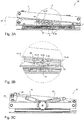
- the Figure 2A shows a suspension device 2 according to the invention of a vehicle seat 1 according to a preferred embodiment in a top view.
- a connecting part 8 which has a first passage 36 and a second passage 37, a first spring rod 6 extending through the first passage 36 and a second spring rod 14 extending through the second passage 37.
- the passages 36, 37 here extend in a vehicle seat longitudinal direction L.
- a third passage 40 can also be seen through which the pivot axis 5 extends, the pivot axis 5 being in operative connection with the connecting part 8. It is also conceivable that the passages 36, 37 are arranged to run in the vehicle seat width direction B.
- the connecting part 8 is furthermore with a rocker-like structure 21 comprising a first rocker element 19 and a second rocker element 20, which are connected to one another by a central element 41.
- the middle element 41 has passages 36, 37, 40.
- the suspension device 2 also has a rotary knob 39 which is connected to the pivot axis 5.
- the pivot axis 5 By operating the rotary knob 39, that is to say by turning the rotary knob, the pivot axis 5 is also rotated about its own axis.
- the connecting part 8 By rotating the pivot axis 5, the connecting part 8 is displaced backwards or forwards in the longitudinal direction L of the vehicle seat, whereby the spring properties of the spring device 2 can be adjusted.
- a first stop element 38 and a second stop element 42 are provided, which limit the displacement of the connecting part 8 in the vehicle seat longitudinal direction L or vehicle seat width direction B.
- the first stop element 38 is arranged such that the connecting element 8 is positioned in a central position when it reaches the first stop element 38, that is to say that the connecting part 8 is symmetrical to the center of the upper part 3, the center in the longitudinal direction L of the vehicle seat being meant.
- a damping device 27 is also shown in FIG Figure 2A can be seen, with a damper 30, several dampers 30 being provided here.
- FIG. 11 shows a front view of FIG Figure 2A .
- FIG. 2B A cross-section through the connecting part 8 is shown, and the connecting part 8 has a rocker-like structure 21, with a first end 22 and a second end 23.
- a first rocker element 19 is located at the first end 22 of the structure 21 and at the second end 23 a second rocker element 20 is arranged in the structure.
- Each rocker element 19, 20 has a trapezoidal area 24 and a rectangular area 25, this configuration (trapezoid, rectangle) relating to the cross section shown.
- the rectangular area 25 is arranged above the trapezoidal area 24, viewed in the vehicle seat height direction H, and is in operative contact with the upper part 3.
- the middle element 41 has the first passage 36, the second passage 37 and the third passage 40, the first spring rod 6 passing through the first passage 36, the second spring rod 14 passing through the second passage and the pivot axis 5 passing through the third passage 40 extends.
- the middle element also comprises a rocker point 43, by means of which the connecting part 8 is operatively connected to the lower part 4.
- the central element 41 is not in operative contact with the upper part 3, but only the first rocker element 19 and the second rocker element 20, in particular the rectangular area 25.
- the rectangular area 25 can be made of different materials, for example from a material with poor suspension and damping properties.
- the material is particularly preferably a slidable material.
- the Figure 2D shows a front view of the spring device 2, wherein a damping device is provided with a first damper 30 with a first end 31 and a second end 32, the first end 31 being pivotably connected to the lower part 4 by means of a first pivot axis 44 and the second end 32 is connected to a first lever element 28, the first lever element 28 being pivotably connected to the lower part 4 by means of a second pivot axis 45 and a second lever element 29 being provided which is pivotable by means of a third pivot axis 46 with the first lever element 28 and pivotable by means of a fourth pivot axis 47 is connected to the upper part 3.
- a damping device is provided with a first damper 30 with a first end 31 and a second end 32, the first end 31 being pivotably connected to the lower part 4 by means of a first pivot axis 44 and the second end 32 is connected to a first lever element 28, the first lever element 28 being pivotably connected to the lower part 4 by means of a second pivot axis 45 and a second lever
- the Figure 3A shows the spring device 2 in a deflected operating state 35, that is to say that the upper part 3 performs a pivoting movement with respect to the lower part 4. Since here the connecting part 8 is in operative contact on the one hand with the upper part 3, the connecting part 8 is also pivoted about the pivot axis 5. This has the consequence that the passages 36, 37 are also pivoted about the pivot axis 5 and consequently also the first spring rod 6 and the second spring rod 14; sometimes the spring bars 6, 14 are elastically deformed. Likewise, the connecting part 8 is in operative contact with the lower part 4 by means of the rocker point 43, so that the connecting part 8 is pivoted about this rocker point 43.
- the upper part 3 and the lower part 4 were arranged essentially parallel to one another in the normal operating state 34, the upper part 3 and the lower part 4 now enclose an angle 49 in the deflected operating state 35 and the first spring bar 6 and the second spring bar 14 are now around one The value of a deflection 48 in the vehicle seat height direction H shifted to one another.
- the Figure 3B shows an enlargement of the area B of FIG Figure 3A .
- the pivot axis 5 is not changed in its position or location by the pivoting movement.
- a side 50 of the trapezoidal area 24 of the first rocker element 19 can also be seen, which includes the rocker point 43 and which can function as a limitation of the pivoting movement of the upper part 3. If the side 50 is in contact with the lower part 4, further pivoting of the upper part 3 relative to the lower part 4 in this direction is no longer possible. The same naturally applies to the further trapezoidal area 24 of the second rocker element 20.
- the Figure 3C shows just like the Figure 2D a front view of the spring device 2, but in the deflected operating state 35.
- the Figure 3C the movement of the first lever element 28 and the second lever element 29 can be seen particularly well.
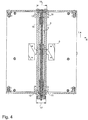
- the Figure 4 shows a particularly preferred embodiment of the spring device 2, the first end 12 of the first spring rod 6 and the first end 15 of the second spring rod 14 at a first distance 17 and the second end 13 of the first spring rod 6 and the second end 16 of the second spring rod 14 are arranged at a second distance 18 from one another.
- the respective distance 17, 18 is measured in the vehicle seat width direction B or the vehicle seat longitudinal direction L.
- the respective distance 17, 18 from the most distant points of the spring bars 6, 14 measured.
- the first distance 17 is smaller than the second distance 18, that is to say in particular that the spring bars 6, 14 do not run parallel to one another, but at an angle to one another.
- the Figures 5A and 5B show the connecting part 8 in the central position 51 and in a displaced position 52, the displaced position 52 being shown in dotted lines.
- the Figure 5A Fig. 3 is a perspective view showing Figure 5B a top view.
- the central position 51 and the displaced position 52 are the maximum positions of the connecting part 8, that is to say that the connecting part 8 can only assume positions between the central position 51 and the displaced position 52, in particular continuously.
- the displacement of the connecting part 8 is limited by a first stop element 38 and a second stop element 42.
Landscapes
- Engineering & Computer Science (AREA)
- Aviation & Aerospace Engineering (AREA)
- Transportation (AREA)
- Mechanical Engineering (AREA)
- Seats For Vehicles (AREA)
- Fluid-Damping Devices (AREA)
- Vehicle Body Suspensions (AREA)
Claims (12)
- Siège de véhicule (1) comportant un dispositif à ressort (2) pour l'amortissement de mouvements de pivotement d'une partie supérieure (3) du siège de véhicule (1) par rapport à une partie inférieure (4) du siège de véhicule (1) autour d'un axe de pivotement (5) disposé s'étendant dans une direction longitudinale (L) du siège de véhicule ou une direction de la largeur (B) du siège de véhicule,
caractérisé par le fait que
le dispositif à ressort (2) présente une première tige à ressort (6) élastiquement déformable en direction transversale et une partie de liaison (8) apte à pivoter autour de l'axe de pivotement (5) relie la première tige à ressort (6) et l'axe de pivotement (5) afin de déformer élastiquement la première tige à ressort (6) lors d'un pivotement de la partie supérieure (3). - Siège de véhicule (1) selon la revendication 1,
caractérisé par le fait que
l'axe de pivotement (5) est, de préférence, conçu en tant qu'axe de palier et l'axe de pivotement (5) présente une première extrémité (10) et une seconde extrémité (11), la première extrémité (10) et la seconde extrémité (11) étant reliées de façon pivotante à la partie inférieure (4) du siège de véhicule. - Siège de véhicule (1) selon l'une des revendications 1 ou 2,
caractérisé par le fait que
la première tige à ressort (6) présente une première extrémité (12) et une seconde extrémité (13), la première extrémité (12) et la seconde extrémité (13) étant reliées à la partie inférieure (4) du siège de véhicule. - Siège de véhicule (1) selon l'une des revendications 1 à 3,
caractérisé par le fait que
la partie de liaison (8) est reliée à l'axe de pivotement (5) de telle sorte que, lors d'une rotation de l'axe de pivotement (5), la partie de liaison (8) est déplaçable le long de l'axe de pivotement (5). - Siège de véhicule (1) selon l'une des revendications 1 à 4,
caractérisé par le fait que
le dispositif à ressort (2) comporte une seconde tige à ressort (14) déformable en direction transversale, laquelle présente une première extrémité (15) et une seconde extrémité (16), la première extrémité (15) et la seconde extrémité (16) étant reliées à la partie inférieure (4) du siège de véhicule et la partie de liaison (8) reliant la seconde tige à ressort (14) et l'axe de pivotement (5). - Siège de véhicule (1) selon la revendication 5,
caractérisé par le fait que
la première extrémité (13) de la première tige à ressort (6) et la première extrémité (13) de la seconde tige à ressort (14) présentent une première distance (17) l'une par rapport à l'autre et la seconde extrémité de la première tige à ressort (13) et la seconde extrémité (16) de la seconde tige à ressort (14) présentent une seconde distance (18) l'une par rapport à l'autre, la première distance (17) étant plus petite que la seconde distance (18). - Siège de véhicule (1) selon l'une des revendications 1 à 6,
caractérisé par le fait que
la partie de liaison (8) présente une structure (21) de type à bascule, un premier élément basculant (19) étant disposé à une première extrémité (22) de la structure (21) de type à bascule et un second élément basculant (20) étant disposé à une seconde extrémité (23) de la structure (21) de type à bascule, le premier élément basculant (19) et le second élément basculant (20) étant en contact fonctionnel avec la partie supérieure (3). - Siège de véhicule (1) selon la revendication 7,
caractérisé par le fait que
le premier élément basculant (19) et le second élément basculant (20) présentent chacun une première région (24), laquelle est conçue de forme trapézoïdale en section transversale, et une seconde région (25), laquelle est conçue rectangulaire en section transversale. - Siège de véhicule (1) selon l'une des revendications 1 à 8,
caractérisé par le fait que
le siège de véhicule (1) comporte une suspension horizontale longitudinale (26), la suspension horizontale longitudinale (26) étant disposée au-dessous du dispositif à ressort (2) lorsqu'elle est vue dans une direction de la hauteur (H) du siège de véhicule. - Siège de véhicule (1) selon l'une des revendications 1 à 9,
caractérisé par le fait que
le siège de véhicule (1) présente un dispositif d'amortissement (27) ayant au moins un amortisseur (30), lequel est relié de façon pivotante à la partie inférieure (4) par une première extrémité (31) et à la partie supérieure (3) par une seconde extrémité (32). - Siège de véhicule (1) selon la revendication 10,
caractérisé par le fait qu'
au moins un premier élément levier (28) est prévu, lequel est relié par une première extrémité de façon pivotante à la partie inférieure (4) et par une seconde extrémité de façon pivotante à la seconde extrémité de l'amortisseur (32), et par le fait qu'au moins un deuxième élément levier (29) est prévu, lequel est relié de façon pivotante au premier élément levier (28). - Siège de véhicule (1) selon l'une des revendications précédentes,
caractérisé par le fait que
la première tige à ressort (6) et l'axe de pivotement (5) sont disposés dans un plan commun (7).
Applications Claiming Priority (1)
| Application Number | Priority Date | Filing Date | Title |
|---|---|---|---|
| DE102018112004.4A DE102018112004B4 (de) | 2018-05-18 | 2018-05-18 | Fahrzeugsitz mit einer Federeinrichtung |
Publications (2)
| Publication Number | Publication Date |
|---|---|
| EP3569443A1 EP3569443A1 (fr) | 2019-11-20 |
| EP3569443B1 true EP3569443B1 (fr) | 2020-08-26 |
Family
ID=66529899
Family Applications (1)
| Application Number | Title | Priority Date | Filing Date |
|---|---|---|---|
| EP19174147.9A Active EP3569443B1 (fr) | 2018-05-18 | 2019-05-13 | Siège de véhicule doté d'un dispositif à ressort |
Country Status (3)
| Country | Link |
|---|---|
| EP (1) | EP3569443B1 (fr) |
| CN (1) | CN110497827B (fr) |
| DE (1) | DE102018112004B4 (fr) |
Families Citing this family (5)
| Publication number | Priority date | Publication date | Assignee | Title |
|---|---|---|---|---|
| DE102019134238B4 (de) | 2019-12-13 | 2023-09-14 | Grammer Aktiengesellschaft | Fahrzeugsitz mit Scherengestellanordnung |
| DE102019134233A1 (de) | 2019-12-13 | 2021-06-17 | Grammer Aktiengesellschaft | Fahrzeugsitz mit einer Federeinheit zum Federn von Wank- und Vertikalfederbewegungen |
| DE102019134244B4 (de) | 2019-12-13 | 2024-08-01 | Grammer Aktiengesellschaft | Fahrzeugsitz mit Scherengestellanordnung |
| DE102019134237B4 (de) | 2019-12-13 | 2024-05-29 | Grammer Aktiengesellschaft | Fahrzeugsitz mit einer Federeinheit zum Federn von Wank- und Vertikalfederbewegungen |
| DE102019134234B4 (de) * | 2019-12-13 | 2024-05-29 | Grammer Aktiengesellschaft | Fahrzeugsitz mit einer Federeinheit zum Federn von Wank- und Vertikalfederbewegungen |
Family Cites Families (19)
| Publication number | Priority date | Publication date | Assignee | Title |
|---|---|---|---|---|
| DE499488C (de) * | 1929-02-20 | 1930-06-06 | Max Naumann | Federnder Sitz fuer Fahrzeuge, insbesondere fuer Kraftfahrzeuge |
| US3098676A (en) * | 1961-04-20 | 1963-07-23 | Bostrom Corp | Seat suspension system |
| FR1543275A (fr) * | 1967-07-31 | 1968-10-25 | Peugeot | Nouvel agencement, à absorption d'énergie, d'un siège sur un véhicule |
| US3632076A (en) * | 1970-02-09 | 1972-01-04 | Thomas J Rogers Jr | Self-leveling seat structure |
| EP0352256B1 (fr) * | 1987-03-11 | 1993-06-02 | WALLIN, Jan | Dispositif automatique de mise a niveau |
| CN2309244Y (zh) * | 1998-01-24 | 1999-03-03 | 巢凯年 | 车辆坐椅减振架 |
| DE10040535C1 (de) * | 2000-08-18 | 2001-10-18 | Grammer Ag | Gefederter Fahrzeugsitz |
| ATE296216T1 (de) * | 2002-03-22 | 2005-06-15 | Milsco Mfg A Unit Of Jason Inc | Sitzaufhängung |
| US6793284B1 (en) * | 2003-03-19 | 2004-09-21 | L & P Property Management Company | Steel spring with dwell for chairs |
| JP2004291940A (ja) * | 2003-03-28 | 2004-10-21 | T S Tec Kk | 車両用シート |
| CN101495012A (zh) * | 2006-03-24 | 2009-07-29 | 赫尔曼米勒有限公司 | 家具件 |
| US7490903B2 (en) * | 2006-05-23 | 2009-02-17 | Ruppe Fredy L | Tiltable seat mounting apparatus |
| DE102007009170B4 (de) * | 2007-02-21 | 2014-10-30 | Johnson Controls Components Gmbh & Co. Kg | Fahrzeugsitz, insbesondere Nutzfahrzeugsitz |
| CN201914134U (zh) * | 2010-11-25 | 2011-08-03 | 朱斯忠 | 车载平衡座椅 |
| DE102011009543B4 (de) * | 2011-01-27 | 2014-06-26 | Isringhausen Gmbh & Co. Kg | Horizontalschwingsystem eines Fahrersitzes |
| CN202147608U (zh) * | 2011-06-30 | 2012-02-22 | 杨银芝 | 一种自动调节坐架 |
| US10046677B2 (en) | 2013-04-23 | 2018-08-14 | Clearmotion Acquisition I Llc | Seat system for a vehicle |
| DE102015121764B4 (de) * | 2015-12-14 | 2023-08-31 | Grammer Aktiengesellschaft | Fahrzeugschwingungsvorrichtung |
| CN107399254B (zh) * | 2017-06-22 | 2019-05-31 | 江苏大学 | 一种履带式谷物联合收割机浮筏式驾驶座椅结构 |
-
2018
- 2018-05-18 DE DE102018112004.4A patent/DE102018112004B4/de active Active
-
2019
- 2019-05-13 EP EP19174147.9A patent/EP3569443B1/fr active Active
- 2019-05-17 CN CN201910411959.7A patent/CN110497827B/zh active Active
Non-Patent Citations (1)
| Title |
|---|
| None * |
Also Published As
| Publication number | Publication date |
|---|---|
| DE102018112004A1 (de) | 2019-11-21 |
| CN110497827A (zh) | 2019-11-26 |
| EP3569443A1 (fr) | 2019-11-20 |
| DE102018112004B4 (de) | 2021-08-05 |
| CN110497827B (zh) | 2022-02-22 |
Similar Documents
| Publication | Publication Date | Title |
|---|---|---|
| EP3569443B1 (fr) | Siège de véhicule doté d'un dispositif à ressort | |
| EP3680129B1 (fr) | Siège de véhicule | |
| EP3572275B1 (fr) | Siège de véhicule | |
| EP3428009B1 (fr) | Siège de véhicule doté d'un amortisseur réglable | |
| DE3500529C2 (fr) | ||
| DE102018124507B4 (de) | Fahrzeugsitz mit Nickfedereinheit | |
| EP3178691B1 (fr) | Système de suspension | |
| EP3409531A1 (fr) | Guidage à rouleaux | |
| DE3042604A1 (de) | Gefederter fahrersitz mit einem scherengestell | |
| EP3263397B1 (fr) | Système de suspension | |
| EP3181397B1 (fr) | Dispositif de vibration de véhicule | |
| EP3835123B1 (fr) | Siège de véhicule doté d'unité de ressort permettant de faire ressort du mouvement de ressort vertical et de roulis | |
| EP3501889A1 (fr) | Siège de véhicule et suspension horizontale longitudinale | |
| EP3335929B1 (fr) | Siège de véhicule doté de suspension | |
| EP3835121B1 (fr) | Siège de véhicule doté d'une unité de ressort permettant de faire ressort du mouvement de roulis et de ressort vertical | |
| AT517147B1 (de) | Ausleger für ein Nutzfahrzeug | |
| EP3569444B1 (fr) | Siège de véhicule doté d'un dispositif d'amortissement | |
| DE102020123061B4 (de) | Federelement und Fahrzeugsitz mit Federelement | |
| DE102018112027B4 (de) | Fahrzeugsitz mit einer Federeinrichtung | |
| DE102015108229A1 (de) | Zuggabel für ein Anhängerfahrzeug | |
| WO2021213925A1 (fr) | Siège de véhicule | |
| DE7130366U (de) | Fahrersitz |
Legal Events
| Date | Code | Title | Description |
|---|---|---|---|
| PUAI | Public reference made under article 153(3) epc to a published international application that has entered the european phase |
Free format text: ORIGINAL CODE: 0009012 |
|
| STAA | Information on the status of an ep patent application or granted ep patent |
Free format text: STATUS: REQUEST FOR EXAMINATION WAS MADE |
|
| 17P | Request for examination filed |
Effective date: 20190829 |
|
| AK | Designated contracting states |
Kind code of ref document: A1 Designated state(s): AL AT BE BG CH CY CZ DE DK EE ES FI FR GB GR HR HU IE IS IT LI LT LU LV MC MK MT NL NO PL PT RO RS SE SI SK SM TR |
|
| AX | Request for extension of the european patent |
Extension state: BA ME |
|
| GRAJ | Information related to disapproval of communication of intention to grant by the applicant or resumption of examination proceedings by the epo deleted |
Free format text: ORIGINAL CODE: EPIDOSDIGR1 |
|
| GRAP | Despatch of communication of intention to grant a patent |
Free format text: ORIGINAL CODE: EPIDOSNIGR1 |
|
| REG | Reference to a national code |
Ref country code: DE Ref legal event code: R079 Ref document number: 502019000170 Country of ref document: DE Free format text: PREVIOUS MAIN CLASS: B60N0002390000 Ipc: B60N0002540000 |
|
| GRAP | Despatch of communication of intention to grant a patent |
Free format text: ORIGINAL CODE: EPIDOSNIGR1 |
|
| STAA | Information on the status of an ep patent application or granted ep patent |
Free format text: STATUS: GRANT OF PATENT IS INTENDED |
|
| RIC1 | Information provided on ipc code assigned before grant |
Ipc: B60N 2/50 20060101ALI20200424BHEP Ipc: B60N 2/39 20060101AFI20200424BHEP Ipc: B60N 2/02 20060101ALI20200424BHEP |
|
| INTG | Intention to grant announced |
Effective date: 20200515 |
|
| RIN1 | Information on inventor provided before grant (corrected) |
Inventor name: IRRGANG, ANDREAS Inventor name: HALLER, ERWIN Inventor name: KRIVENKOV, KONSTANTIN |
|
| INTC | Intention to grant announced (deleted) | ||
| RIC1 | Information provided on ipc code assigned before grant |
Ipc: B60N 2/39 20060101ALI20200514BHEP Ipc: B60N 2/54 20060101AFI20200514BHEP Ipc: B60N 2/02 20060101ALI20200514BHEP Ipc: B60N 2/50 20060101ALI20200514BHEP |
|
| INTG | Intention to grant announced |
Effective date: 20200528 |
|
| GRAS | Grant fee paid |
Free format text: ORIGINAL CODE: EPIDOSNIGR3 |
|
| GRAA | (expected) grant |
Free format text: ORIGINAL CODE: 0009210 |
|
| STAA | Information on the status of an ep patent application or granted ep patent |
Free format text: STATUS: THE PATENT HAS BEEN GRANTED |
|
| AK | Designated contracting states |
Kind code of ref document: B1 Designated state(s): AL AT BE BG CH CY CZ DE DK EE ES FI FR GB GR HR HU IE IS IT LI LT LU LV MC MK MT NL NO PL PT RO RS SE SI SK SM TR |
|
| REG | Reference to a national code |
Ref country code: GB Ref legal event code: FG4D Free format text: NOT ENGLISH |
|
| REG | Reference to a national code |
Ref country code: CH Ref legal event code: EP |
|
| REG | Reference to a national code |
Ref country code: AT Ref legal event code: REF Ref document number: 1306061 Country of ref document: AT Kind code of ref document: T Effective date: 20200915 |
|
| REG | Reference to a national code |
Ref country code: IE Ref legal event code: FG4D Free format text: LANGUAGE OF EP DOCUMENT: GERMAN |
|
| REG | Reference to a national code |
Ref country code: DE Ref legal event code: R096 Ref document number: 502019000170 Country of ref document: DE |
|
| RAP2 | Party data changed (patent owner data changed or rights of a patent transferred) |
Owner name: GRAMMER AG |
|
| REG | Reference to a national code |
Ref country code: SE Ref legal event code: TRGR |
|
| REG | Reference to a national code |
Ref country code: LT Ref legal event code: MG4D |
|
| PG25 | Lapsed in a contracting state [announced via postgrant information from national office to epo] |
Ref country code: NO Free format text: LAPSE BECAUSE OF FAILURE TO SUBMIT A TRANSLATION OF THE DESCRIPTION OR TO PAY THE FEE WITHIN THE PRESCRIBED TIME-LIMIT Effective date: 20201126 Ref country code: BG Free format text: LAPSE BECAUSE OF FAILURE TO SUBMIT A TRANSLATION OF THE DESCRIPTION OR TO PAY THE FEE WITHIN THE PRESCRIBED TIME-LIMIT Effective date: 20201126 Ref country code: GR Free format text: LAPSE BECAUSE OF FAILURE TO SUBMIT A TRANSLATION OF THE DESCRIPTION OR TO PAY THE FEE WITHIN THE PRESCRIBED TIME-LIMIT Effective date: 20201127 Ref country code: LT Free format text: LAPSE BECAUSE OF FAILURE TO SUBMIT A TRANSLATION OF THE DESCRIPTION OR TO PAY THE FEE WITHIN THE PRESCRIBED TIME-LIMIT Effective date: 20200826 Ref country code: FI Free format text: LAPSE BECAUSE OF FAILURE TO SUBMIT A TRANSLATION OF THE DESCRIPTION OR TO PAY THE FEE WITHIN THE PRESCRIBED TIME-LIMIT Effective date: 20200826 Ref country code: HR Free format text: LAPSE BECAUSE OF FAILURE TO SUBMIT A TRANSLATION OF THE DESCRIPTION OR TO PAY THE FEE WITHIN THE PRESCRIBED TIME-LIMIT Effective date: 20200826 Ref country code: PT Free format text: LAPSE BECAUSE OF FAILURE TO SUBMIT A TRANSLATION OF THE DESCRIPTION OR TO PAY THE FEE WITHIN THE PRESCRIBED TIME-LIMIT Effective date: 20201228 |
|
| REG | Reference to a national code |
Ref country code: NL Ref legal event code: MP Effective date: 20200826 |
|
| PG25 | Lapsed in a contracting state [announced via postgrant information from national office to epo] |
Ref country code: RS Free format text: LAPSE BECAUSE OF FAILURE TO SUBMIT A TRANSLATION OF THE DESCRIPTION OR TO PAY THE FEE WITHIN THE PRESCRIBED TIME-LIMIT Effective date: 20200826 Ref country code: LV Free format text: LAPSE BECAUSE OF FAILURE TO SUBMIT A TRANSLATION OF THE DESCRIPTION OR TO PAY THE FEE WITHIN THE PRESCRIBED TIME-LIMIT Effective date: 20200826 Ref country code: PL Free format text: LAPSE BECAUSE OF FAILURE TO SUBMIT A TRANSLATION OF THE DESCRIPTION OR TO PAY THE FEE WITHIN THE PRESCRIBED TIME-LIMIT Effective date: 20200826 Ref country code: NL Free format text: LAPSE BECAUSE OF FAILURE TO SUBMIT A TRANSLATION OF THE DESCRIPTION OR TO PAY THE FEE WITHIN THE PRESCRIBED TIME-LIMIT Effective date: 20200826 Ref country code: IS Free format text: LAPSE BECAUSE OF FAILURE TO SUBMIT A TRANSLATION OF THE DESCRIPTION OR TO PAY THE FEE WITHIN THE PRESCRIBED TIME-LIMIT Effective date: 20201226 |
|
| PG25 | Lapsed in a contracting state [announced via postgrant information from national office to epo] |
Ref country code: SM Free format text: LAPSE BECAUSE OF FAILURE TO SUBMIT A TRANSLATION OF THE DESCRIPTION OR TO PAY THE FEE WITHIN THE PRESCRIBED TIME-LIMIT Effective date: 20200826 Ref country code: RO Free format text: LAPSE BECAUSE OF FAILURE TO SUBMIT A TRANSLATION OF THE DESCRIPTION OR TO PAY THE FEE WITHIN THE PRESCRIBED TIME-LIMIT Effective date: 20200826 Ref country code: DK Free format text: LAPSE BECAUSE OF FAILURE TO SUBMIT A TRANSLATION OF THE DESCRIPTION OR TO PAY THE FEE WITHIN THE PRESCRIBED TIME-LIMIT Effective date: 20200826 Ref country code: CZ Free format text: LAPSE BECAUSE OF FAILURE TO SUBMIT A TRANSLATION OF THE DESCRIPTION OR TO PAY THE FEE WITHIN THE PRESCRIBED TIME-LIMIT Effective date: 20200826 Ref country code: EE Free format text: LAPSE BECAUSE OF FAILURE TO SUBMIT A TRANSLATION OF THE DESCRIPTION OR TO PAY THE FEE WITHIN THE PRESCRIBED TIME-LIMIT Effective date: 20200826 |
|
| REG | Reference to a national code |
Ref country code: DE Ref legal event code: R097 Ref document number: 502019000170 Country of ref document: DE |
|
| PG25 | Lapsed in a contracting state [announced via postgrant information from national office to epo] |
Ref country code: ES Free format text: LAPSE BECAUSE OF FAILURE TO SUBMIT A TRANSLATION OF THE DESCRIPTION OR TO PAY THE FEE WITHIN THE PRESCRIBED TIME-LIMIT Effective date: 20200826 Ref country code: AL Free format text: LAPSE BECAUSE OF FAILURE TO SUBMIT A TRANSLATION OF THE DESCRIPTION OR TO PAY THE FEE WITHIN THE PRESCRIBED TIME-LIMIT Effective date: 20200826 |
|
| PG25 | Lapsed in a contracting state [announced via postgrant information from national office to epo] |
Ref country code: SK Free format text: LAPSE BECAUSE OF FAILURE TO SUBMIT A TRANSLATION OF THE DESCRIPTION OR TO PAY THE FEE WITHIN THE PRESCRIBED TIME-LIMIT Effective date: 20200826 |
|
| PLBE | No opposition filed within time limit |
Free format text: ORIGINAL CODE: 0009261 |
|
| STAA | Information on the status of an ep patent application or granted ep patent |
Free format text: STATUS: NO OPPOSITION FILED WITHIN TIME LIMIT |
|
| PG25 | Lapsed in a contracting state [announced via postgrant information from national office to epo] |
Ref country code: IT Free format text: LAPSE BECAUSE OF FAILURE TO SUBMIT A TRANSLATION OF THE DESCRIPTION OR TO PAY THE FEE WITHIN THE PRESCRIBED TIME-LIMIT Effective date: 20200826 |
|
| 26N | No opposition filed |
Effective date: 20210527 |
|
| REG | Reference to a national code |
Ref country code: SE Ref legal event code: RPOT |
|
| PG25 | Lapsed in a contracting state [announced via postgrant information from national office to epo] |
Ref country code: LU Free format text: LAPSE BECAUSE OF NON-PAYMENT OF DUE FEES Effective date: 20210513 Ref country code: MC Free format text: LAPSE BECAUSE OF FAILURE TO SUBMIT A TRANSLATION OF THE DESCRIPTION OR TO PAY THE FEE WITHIN THE PRESCRIBED TIME-LIMIT Effective date: 20200826 |
|
| REG | Reference to a national code |
Ref country code: BE Ref legal event code: MM Effective date: 20210531 |
|
| PG25 | Lapsed in a contracting state [announced via postgrant information from national office to epo] |
Ref country code: IE Free format text: LAPSE BECAUSE OF NON-PAYMENT OF DUE FEES Effective date: 20210513 |
|
| PG25 | Lapsed in a contracting state [announced via postgrant information from national office to epo] |
Ref country code: FR Free format text: LAPSE BECAUSE OF NON-PAYMENT OF DUE FEES Effective date: 20210531 |
|
| PG25 | Lapsed in a contracting state [announced via postgrant information from national office to epo] |
Ref country code: BE Free format text: LAPSE BECAUSE OF NON-PAYMENT OF DUE FEES Effective date: 20210531 |
|
| REG | Reference to a national code |
Ref country code: CH Ref legal event code: PL |
|
| PG25 | Lapsed in a contracting state [announced via postgrant information from national office to epo] |
Ref country code: LI Free format text: LAPSE BECAUSE OF NON-PAYMENT OF DUE FEES Effective date: 20220531 Ref country code: CH Free format text: LAPSE BECAUSE OF NON-PAYMENT OF DUE FEES Effective date: 20220531 |
|
| PG25 | Lapsed in a contracting state [announced via postgrant information from national office to epo] |
Ref country code: CY Free format text: LAPSE BECAUSE OF FAILURE TO SUBMIT A TRANSLATION OF THE DESCRIPTION OR TO PAY THE FEE WITHIN THE PRESCRIBED TIME-LIMIT Effective date: 20200826 |
|
| PG25 | Lapsed in a contracting state [announced via postgrant information from national office to epo] |
Ref country code: HU Free format text: LAPSE BECAUSE OF FAILURE TO SUBMIT A TRANSLATION OF THE DESCRIPTION OR TO PAY THE FEE WITHIN THE PRESCRIBED TIME-LIMIT; INVALID AB INITIO Effective date: 20190513 |
|
| PG25 | Lapsed in a contracting state [announced via postgrant information from national office to epo] |
Ref country code: SI Free format text: LAPSE BECAUSE OF FAILURE TO SUBMIT A TRANSLATION OF THE DESCRIPTION OR TO PAY THE FEE WITHIN THE PRESCRIBED TIME-LIMIT Effective date: 20200826 |
|
| GBPC | Gb: european patent ceased through non-payment of renewal fee |
Effective date: 20230513 |
|
| PG25 | Lapsed in a contracting state [announced via postgrant information from national office to epo] |
Ref country code: MK Free format text: LAPSE BECAUSE OF FAILURE TO SUBMIT A TRANSLATION OF THE DESCRIPTION OR TO PAY THE FEE WITHIN THE PRESCRIBED TIME-LIMIT Effective date: 20200826 Ref country code: GB Free format text: LAPSE BECAUSE OF NON-PAYMENT OF DUE FEES Effective date: 20230513 |
|
| PGFP | Annual fee paid to national office [announced via postgrant information from national office to epo] |
Ref country code: DE Payment date: 20240517 Year of fee payment: 6 |
|
| PGFP | Annual fee paid to national office [announced via postgrant information from national office to epo] |
Ref country code: TR Payment date: 20240502 Year of fee payment: 6 Ref country code: SE Payment date: 20240522 Year of fee payment: 6 |