EP3569320A1 - Device and method for applying adhesive to printed material - Google Patents
Device and method for applying adhesive to printed material Download PDFInfo
- Publication number
- EP3569320A1 EP3569320A1 EP18172483.2A EP18172483A EP3569320A1 EP 3569320 A1 EP3569320 A1 EP 3569320A1 EP 18172483 A EP18172483 A EP 18172483A EP 3569320 A1 EP3569320 A1 EP 3569320A1
- Authority
- EP
- European Patent Office
- Prior art keywords
- nozzle
- adhesive
- application
- slot
- closure
- Prior art date
- Legal status (The legal status is an assumption and is not a legal conclusion. Google has not performed a legal analysis and makes no representation as to the accuracy of the status listed.)
- Withdrawn
Links
Images
Classifications
-
- B—PERFORMING OPERATIONS; TRANSPORTING
- B05—SPRAYING OR ATOMISING IN GENERAL; APPLYING FLUENT MATERIALS TO SURFACES, IN GENERAL
- B05C—APPARATUS FOR APPLYING FLUENT MATERIALS TO SURFACES, IN GENERAL
- B05C5/00—Apparatus in which liquid or other fluent material is projected, poured or allowed to flow on to the surface of the work
- B05C5/02—Apparatus in which liquid or other fluent material is projected, poured or allowed to flow on to the surface of the work the liquid or other fluent material being discharged through an outlet orifice by pressure, e.g. from an outlet device in contact or almost in contact, with the work
- B05C5/0254—Coating heads with slot-shaped outlet
- B05C5/0262—Coating heads with slot-shaped outlet adjustable in width, i.e. having lips movable relative to each other in order to modify the slot width, e.g. to close it
-
- B—PERFORMING OPERATIONS; TRANSPORTING
- B05—SPRAYING OR ATOMISING IN GENERAL; APPLYING FLUENT MATERIALS TO SURFACES, IN GENERAL
- B05C—APPARATUS FOR APPLYING FLUENT MATERIALS TO SURFACES, IN GENERAL
- B05C5/00—Apparatus in which liquid or other fluent material is projected, poured or allowed to flow on to the surface of the work
- B05C5/02—Apparatus in which liquid or other fluent material is projected, poured or allowed to flow on to the surface of the work the liquid or other fluent material being discharged through an outlet orifice by pressure, e.g. from an outlet device in contact or almost in contact, with the work
- B05C5/0204—Apparatus in which liquid or other fluent material is projected, poured or allowed to flow on to the surface of the work the liquid or other fluent material being discharged through an outlet orifice by pressure, e.g. from an outlet device in contact or almost in contact, with the work for applying liquid or other fluent material to the edges of essentially flat articles
-
- B—PERFORMING OPERATIONS; TRANSPORTING
- B05—SPRAYING OR ATOMISING IN GENERAL; APPLYING FLUENT MATERIALS TO SURFACES, IN GENERAL
- B05C—APPARATUS FOR APPLYING FLUENT MATERIALS TO SURFACES, IN GENERAL
- B05C5/00—Apparatus in which liquid or other fluent material is projected, poured or allowed to flow on to the surface of the work
- B05C5/02—Apparatus in which liquid or other fluent material is projected, poured or allowed to flow on to the surface of the work the liquid or other fluent material being discharged through an outlet orifice by pressure, e.g. from an outlet device in contact or almost in contact, with the work
- B05C5/0254—Coating heads with slot-shaped outlet
- B05C5/0266—Coating heads with slot-shaped outlet adjustable in length, e.g. for coating webs of different width
-
- B—PERFORMING OPERATIONS; TRANSPORTING
- B42—BOOKBINDING; ALBUMS; FILES; SPECIAL PRINTED MATTER
- B42C—BOOKBINDING
- B42C9/00—Applying glue or adhesive peculiar to bookbinding
- B42C9/0006—Applying glue or adhesive peculiar to bookbinding by applying adhesive to a stack of sheets
Definitions
- the invention relates to a device for applying adhesive to printed products, in particular to a book block back, with an application nozzle for surface adhesive application to the printed product and an adhesive supply for applying the application nozzle with adhesive.
- the invention further relates to a method that can be carried out with such a device.
- the object of the invention is to further improve the devices and methods known in the prior art and to enable an extended use of adhesive with reduced complexity.
- the invention is based on the idea of creating an application nozzle with a closable cross-section directly at the outlet or at the application site for cold glue. Accordingly, the invention proposes that the adhesive to be applied is formed by a cold glue, and that the application nozzle has a movable to release a nozzle slot nozzle closure, the nozzle closure in an open position forms a longitudinal edge of the nozzle slot and closes or shuts off the nozzle slot in a closed position.
- a specifically controllable application form is created via a slot nozzle, in which no pre-metering of the required amount of glue is required, so that moving parts in the volume flow or upstream valves in front of the outlet cross-section are dispensable.
- cold glue which per se has a higher viscosity, feasible in practice.
- Cold glue is generally a cold processable glue composition to understand.
- Cold glue is usually formed from an artificial or natural resin dispersion in water. This makes it possible to dispense with external heat sources and environmentally harmful solvents. In the closed position of the nozzle closure no adhesive can escape and mechanical parts stick together unintentionally. In addition, it is then prevented that the adhesive or cold glue comes into contact with ambient air.
- the nozzle closure is in its closed position against a nozzle slot limiting fixed sealing edge of the applicator nozzle sealingly. This ensures that the outlet cross-section can be closed quickly and also optionally to adapt the slot width of the nozzle slot, for example, to different required amounts of adhesive or viscosities or variable.
- a further advantageous embodiment provides that the nozzle closure can be moved back and forth between the closed position and the open position by a drive unit, so that an automatically controllable application process is made possible.
- the drive unit has a pneumatic cylinder or an electromagnetically operating drive coil for moving the nozzle closure.
- the drive unit has a lever linkage for transmitting a drive movement to the nozzle closure.
- a further improvement in terms of equipment can be achieved in that the nozzle closure in a linear guide is in particular slidably guided.
- a centric adaptation to the width of the printed product or book block takes place in that the application nozzle has two limiting jaws, which are adjustable relative to one another at the same distance from the longitudinal center of the nozzle slot, for laterally delimiting the nozzle slot.
- the nozzle closure In order to reduce the surface of the closing contour, it is expedient for the nozzle closure to have a run-on slope for the adhesive which reduces the flow cross-section in the direction of the nozzle slot.
- the adhesive supply device is designed for a gravity-driven adhesive transport to the application nozzle.
- a further improvement in this direction provides that the adhesive supply device has a flexible storage container for adhesive and a weight piece which can be placed on the storage container. For such a reservoir, transport bags for adhesive can be used to avoid transferring.
- the adhesive supply device has an adhesive line which terminates at the application nozzle and is kept free of shut-off devices or valves.
- the application nozzle has a feed chamber for adhesive which is arranged upstream of the nozzle slot and is integrated in a nozzle block.
- a large-area application of glue by means of the slot nozzle can be achieved in that the printed products are guided past the application nozzle arranged underneath by means of a transport device along a transport path.
- the movement of the nozzle closure is controlled by a control unit in accordance with an operative position of the application nozzle relative to the printed product.
- the adhesive application in the operative position takes place without direct physical contact (“non-contact") at a small distance from the applicator nozzle to the book block spine, as it were, via an adhesive column.
- the above-mentioned object is achieved in that an adhesive is applied by means of an application nozzle surface on the printed product, wherein the application nozzle is fed via an adhesive feeder with adhesive, wherein the application nozzle opened in operative or operative position relative to the printed product and otherwise (Without operative relationship) is closed, and wherein a cold glue is used as an adhesive.
- a particularly advantageous measure provides that the printed product is guided past the application nozzle along a transport path, and that the application nozzle is raised after closing to the transport path through a lifting drive. This makes it possible, at the end of the glue application process to avoid re-drawing of the glue (so-called "tailing") and leave no glue residue on the application nozzle, but to apply all the material on the book block.
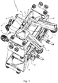
- nozzle application system for cold glue comprises a nozzle device 10 with an application nozzle 12 for surface application of cold glue on the back of a binding book block 14, a Kaltleimzu slaughtering 16 for valve-free supply of cold glue 18 to the application nozzle 12, a control unit 20 for actuating the nozzle device 10 and a transport device 22 for passing the book block 14 at the Application nozzle 12.
- Fig. 1 shows the nozzle device 10 in a perspective view with the nozzle slot 24 pointing upwards in the open position.
- the nozzle slot 24 is oriented with its longitudinal direction transversely to the paper edges of the book block 14 forming sheet stack, so that the cold glue 18 is applied to the passing book block back surface.
- the application nozzle 12 has a nozzle closure 26 which is movable between an open position and a closed position. In the closed position, the nozzle closure 26 abuts against a nozzle slot 24 bounding fixed sealing edge 28 sealingly. The nozzle slot 24 is covered or closed. In the open position, the nozzle closure 26 forms a longitudinal edge of the rectangular nozzle slot 24.
- the nozzle closure 26 is movable by means of a drive unit 30 in a linear guide 32 back and forth.
- pneumatic cylinders 34 or electromagnetic drives can be controlled by means of the control unit 20.
- the drive movement is transmitted via a lever linkage 38 to the nozzle closure 26. It is also possible to adjust the slot width of the nozzle slot 24 via adjusting means 40.
- the application nozzle 12 has two limiting jaws 42, which are mutually adjustable at the same distance from the longitudinal center of the nozzle slot 24. Their mutual distance is automatically adapted to the book block width by an engaging book block 14 on the book block pliers 44.
- the nozzle closure 26 has a flow area in the direction of the nozzle slot 24 toward decreasing run-on slope 46 for the adhesive.
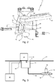
- the nozzle slot 24 is preceded by a cylindrical feed chamber 48, which is integrated or incorporated into a nozzle block 50 located below the nozzle closure 46.
- Fig. 3 illustrates a flexible glue supply bag 52 that is compressed under the weight of an attached weight piece 54 and thereby feeds a cold glue line 56 to the cold glue 18.
- the Kaltleim Arthur 56 opens into the feed chamber 48 and is kept free of shut-off valves or valves or similar fittings, so that a functional impairment and sticking of movable fittings parts is avoided.
- the above-described nozzle application system operates as follows: The cold glue application and correspondingly the opening of the nozzle slot 24 takes place intermittently in the passage of successive book blocks 14. A book block 14 entering the book block tongs 44 is detected by means of a sensor 58. The control unit 20 then controls the nozzle closure 26 from its closed position to its open position, in which cold glue 18 is applied through the nozzle slot 24 as an outlet or mouth cross section to the book block spine. In accordance with this operative relationship, the surface cold glue coating of the complete book block spine takes place until it leaves the application nozzle 12, in which case the nozzle closure 26 is closed again. The order quantity can be adjusted by adjusting the slot width of the Nozzle slot 24 depending on the passage speed of the book block 14 can be adjusted.
Abstract
Die Erfindung betrifft eine Vorrichtung und ein damit ausführbares Verfahren zum Auftragen von Klebstoff auf Druckereierzeugnisse, insbesondere auf einen Buchblockrücken, mit einer Auftragsdüse (12) zum flächigen Klebstoffauftrag auf das Druckereierzeugnis (14) und einer Klebstoffzuführeinrichtung (16) zum Beaufschlagen der Auftragsdüse (12) mit Klebstoff. Erfindungsgemäß wird vorgeschlagen, dass der aufzutragende Klebstoff durch einen Kaltleim (18) gebildet ist, und dass die Auftragsdüse (12) einen zur Freigabe eines Düsenschlitzes (24) beweglichen Düsenverschluss (26) aufweist, wobei der Düsenverschluss (26) in einer Offenstellung einen Längsrand des Düsenschlitzes (24) bildet und in einer Schließstellung den Düsenschlitz (24) verschließt.

Description
Die Erfindung betrifft eine Vorrichtung zum Auftragen von Klebstoff auf Druckereierzeugnisse, insbesondere auf einen Buchblockrücken, mit einer Auftragsdüse zum flächigen Klebstoffauftrag auf das Druckereierzeugnis und einer Klebstoffzuführeinrichtung zum Beaufschlagen der Auftragsdüse mit Klebstoff. Die Erfindung betrifft weiter ein mit einer solchen Vorrichtung durchführbares Verfahren.The invention relates to a device for applying adhesive to printed products, in particular to a book block back, with an application nozzle for surface adhesive application to the printed product and an adhesive supply for applying the application nozzle with adhesive. The invention further relates to a method that can be carried out with such a device.
In der
Ausgehend hiervon liegt der Erfindung die Aufgabe zugrunde, die im Stand der Technik bekannten Vorrichtungen und Verfahren weiter zu verbessern und einen erweiterten Klebstoffeinsatz bei reduzierter Komplexität zu ermöglichen.Proceeding from this, the object of the invention is to further improve the devices and methods known in the prior art and to enable an extended use of adhesive with reduced complexity.
Zur Lösung dieser Aufgabe wird die im Patentanspruch 1 bzw. 14 angegebene Merkmalskombination vorgeschlagen. Vorteilhafte Ausgestaltungen und Weiterbildungen der Erfindung ergeben sich aus den abhängigen Ansprüchen.To solve this problem, the combination of features specified in
Der Erfindung liegt der Gedanke zugrunde, eine Auftragsdüse mit verschließbarem Querschnitt unmittelbar am Austritt bzw. an der Applikationsstelle für Kaltleim zu schaffen. Dementsprechend wird erfindungsgemäß vorgeschlagen, dass der aufzutragende Klebstoff durch einen Kaltleim gebildet ist, und dass die Auftragsdüse einen zur Freigabe eines Düsenschlitzes beweglichen Düsenverschluss aufweist, wobei der Düsenverschluss in einer Offenstellung einen Längsrand des Düsenschlitzes bildet und in einer Schließstellung den Düsenschlitz verschließt bzw. absperrt. Dadurch wird eine gezielt steuerbare Applikationsform über eine Schlitzdüse geschaffen, bei der keine Vordosierung der benötigten Leimmenge erforderlich ist, so dass bewegliche Teile im Volumenstrom bzw. vorgeschaltete Ventile vor dem Austrittsquerschnitt entbehrlich sind. Dadurch ist auch der Auftrag von Kaltleim, der per se eine höhere Viskosität aufweist, in der Praxis realisierbar. Unter Kaltleim ist generell eine kalt verarbeitbare Leimkomposition zu verstehen. Kaltleim ist meist aus einer Kunst- oder Naturharz-Dispersion in Wasser gebildet. Dadurch kann auf externe Heizquellen und umweltschädliche Lösungsmittel verzichtet werden. In der Schließstellung des Düsenverschlusses kann kein Klebstoff austreten und mechanische Teile ungewollt verkleben. Außerdem wird dann verhindert, dass der Klebstoff bzw. Kaltleim mit Umgebungsluft in Berührung kommt.The invention is based on the idea of creating an application nozzle with a closable cross-section directly at the outlet or at the application site for cold glue. Accordingly, the invention proposes that the adhesive to be applied is formed by a cold glue, and that the application nozzle has a movable to release a nozzle slot nozzle closure, the nozzle closure in an open position forms a longitudinal edge of the nozzle slot and closes or shuts off the nozzle slot in a closed position. As a result, a specifically controllable application form is created via a slot nozzle, in which no pre-metering of the required amount of glue is required, so that moving parts in the volume flow or upstream valves in front of the outlet cross-section are dispensable. This is also true the application of cold glue, which per se has a higher viscosity, feasible in practice. Under cold glue is generally a cold processable glue composition to understand. Cold glue is usually formed from an artificial or natural resin dispersion in water. This makes it possible to dispense with external heat sources and environmentally harmful solvents. In the closed position of the nozzle closure no adhesive can escape and mechanical parts stick together unintentionally. In addition, it is then prevented that the adhesive or cold glue comes into contact with ambient air.
Vorteilhafterweise liegt der Düsenverschluss in seiner Schließstellung gegen eine die Düsenschlitz begrenzende feststehende Dichtkante der Auftragsdüse abdichtend an. Dadurch wird erreicht, dass der Austrittsquerschnitt rasch geschlossen werden kann und auch wahlweise zur Anpassung der Schlitzweite des Düsenschlitzes beispielsweise an unterschiedliche benötigte Klebstoffmengen oder Viskositäten oder veränderlich ist.Advantageously, the nozzle closure is in its closed position against a nozzle slot limiting fixed sealing edge of the applicator nozzle sealingly. This ensures that the outlet cross-section can be closed quickly and also optionally to adapt the slot width of the nozzle slot, for example, to different required amounts of adhesive or viscosities or variable.
Eine weitere vorteilhafte Ausführung sieht vor, dass der Düsenverschluss durch eine Antriebseinheit zwischen der Schließstellung und der Offenstellung hin und her beweglich ist, so dass ein automatisch steuerbarer Applikationsprozess ermöglicht wird.A further advantageous embodiment provides that the nozzle closure can be moved back and forth between the closed position and the open position by a drive unit, so that an automatically controllable application process is made possible.
In diesem Zusammenhang ist es auch günstig, wenn die Antriebseinheit einen Pneumatikzylinder oder eine elektromagnetisch arbeitende Antriebsspule zur Bewegung des Düsenverschlusses aufweist.In this context, it is also advantageous if the drive unit has a pneumatic cylinder or an electromagnetically operating drive coil for moving the nozzle closure.
Um den Antrieb räumlich getrennt positionieren zu können, ist es von Vorteil, wenn die Antriebseinheit ein Hebelgestänge zur Übertragung einer Antriebsbewegung auf den Düsenverschluss aufweist.In order to position the drive spatially separated, it is advantageous if the drive unit has a lever linkage for transmitting a drive movement to the nozzle closure.
Eine weitere apparative Verbesserung lässt sich dadurch erreichen, dass der Düsenverschluss in einer Linearführung insbesondere gleitend geführt ist.A further improvement in terms of equipment can be achieved in that the nozzle closure in a linear guide is in particular slidably guided.
Vorteilhafterweise erfolgt eine zentrische Anpassung an die Breite des Druckereierzeugnisses bzw. Buchblocks dadurch, dass die Auftragsdüse zwei in gleichem Abstand zur Längsmitte des Düsenschlitzes gegeneinander verstellbare Begrenzungsbacken zur seitlichen Begrenzung des Düsenschlitzes aufweist.Advantageously, a centric adaptation to the width of the printed product or book block takes place in that the application nozzle has two limiting jaws, which are adjustable relative to one another at the same distance from the longitudinal center of the nozzle slot, for laterally delimiting the nozzle slot.
Für eine einfache mechanische Einstellung ist es günstig, wenn der gegenseitige Abstand der Abdeckbacken durch eine beidseitig an dem Druckereierzeugnis angreifende, insbesondere als Buchblockzange ausgebildete Verstellmechanik selbsttätig einstellbar ist.For a simple mechanical adjustment, it is advantageous if the mutual distance of the cover jaws is automatically adjustable by an attacking on both sides of the printed matter, in particular designed as a book block tongs adjustment.
Um die Fläche der Schließkontur zu reduzieren, ist es günstig, wenn der Düsenverschluss eine den Durchflussquerschnitt in Richtung zu dem Düsenschlitz hin verringernde Anlaufschräge für den Klebstoff aufweist.In order to reduce the surface of the closing contour, it is expedient for the nozzle closure to have a run-on slope for the adhesive which reduces the flow cross-section in the direction of the nozzle slot.
Zur apparativen Vereinfachung ist die Klebstoffzuführeinrichtung für einen schwerkraftgetriebenen Klebstofftransport zu der Auftragsdüse ausgeführt.For simplifying the apparatus, the adhesive supply device is designed for a gravity-driven adhesive transport to the application nozzle.
Eine weitere Verbesserung in dieser Richtung sieht vor, dass die Klebstoffzuführeinrichtung einen flexiblen Vorratsbehälter für Klebstoff und ein auf den Vorratsbehälter aufsetzbares Gewichtsstück aufweist. Für einen solchen Vorratsbehälter lassen sich Transportbeutel für Klebstoff einsetzen, um das Umfüllen zu vermeiden.A further improvement in this direction provides that the adhesive supply device has a flexible storage container for adhesive and a weight piece which can be placed on the storage container. For such a reservoir, transport bags for adhesive can be used to avoid transferring.
Um das Klebstoffsystem nicht zu beeinträchtigen und ein Blockieren mechanischer Teile zu vermeiden, ist es vorteilhaft, wenn die Klebstoffzuführeinrichtung eine an der Auftragsdüse endende, von Absperrorganen oder Ventilen freigehaltene Klebstoffleitung aufweist.In order not to impair the adhesive system and to avoid blocking of mechanical parts, it is advantageous if the adhesive supply device has an adhesive line which terminates at the application nozzle and is kept free of shut-off devices or valves.
Für eine gleichmäßige Klebstoffzufuhr und ein gleichmäßiges Auftragsbild ist es auch von Vorteil, wenn die Auftragsdüse eine dem Düsenschlitz vorgeordnete, in einem Düsenblock integrierte Zuführkammer für Klebstoff aufweist.For a uniform adhesive supply and a uniform application image, it is also advantageous if the application nozzle has a feed chamber for adhesive which is arranged upstream of the nozzle slot and is integrated in a nozzle block.
Ein großflächiger Leimauftrag mittels der Schlitzdüse lässt sich dadurch erreichen, dass die Druckereierzeugnisse mittels einer Transporteinrichtung entlang einer Transportbahn an der darunter angeordneten Auftragsdüse vorbeigeführt sind.A large-area application of glue by means of the slot nozzle can be achieved in that the printed products are guided past the application nozzle arranged underneath by means of a transport device along a transport path.
Zur Verarbeitung großer Stückzahlen ist es vorteilhaft, wenn die Bewegung des Düsenverschlusses durch eine Steuereinheit nach Maßgabe einer Wirkposition der Auftragsdüse relativ zu dem Druckereierzeugnis gesteuert ist. Der Klebstoffauftrag in der Wirkposition erfolgt ohne unmittelbaren körperlichen Kontakt ("non-contact") in einem geringen Abstand der Auftragsdüse zu dem Buchblockrücken gleichsam über eine Klebstoffsäule.For processing large numbers, it is advantageous if the movement of the nozzle closure is controlled by a control unit in accordance with an operative position of the application nozzle relative to the printed product. The adhesive application in the operative position takes place without direct physical contact ("non-contact") at a small distance from the applicator nozzle to the book block spine, as it were, via an adhesive column.
In verfahrensmäßiger Hinsicht wird die eingangs genannte Aufgabe dadurch gelöst, dass ein Klebstoff mittels einer Auftragsdüse flächig auf das Druckereierzeugnis aufgetragen wird, wobei die Auftragsdüse über eine Klebstoffzuführeinrichtung mit Klebstoff gespeist wird, wobei die Auftragsdüse in Wirkbeziehung bzw. Wirkposition relativ zu dem Druckereierzeugnis geöffnet und andernfalls (ohne Wirkbeziehung) geschlossen wird, und wobei ein Kaltleim als Klebstoff eingesetzt wird. Dadurch werden die in Verbindung mit einer erfindungsgemäßen Vorrichtung oben beschriebenen Vorteile gleichermaßen erreicht.In procedural terms, the above-mentioned object is achieved in that an adhesive is applied by means of an application nozzle surface on the printed product, wherein the application nozzle is fed via an adhesive feeder with adhesive, wherein the application nozzle opened in operative or operative position relative to the printed product and otherwise (Without operative relationship) is closed, and wherein a cold glue is used as an adhesive. Thereby, the advantages described above in connection with a device according to the invention are achieved equally.
Eine besonders vorteilhafte Maßnahme sieht vor, dass das Druckereierzeugnis entlang einer Transportbahn an der Auftragsdüse vorbeigeführt wird, und dass die Auftragsdüse nach dem Schließen zu der Transportbahn hin durch einen Hubantrieb angehoben wird. Dadurch ist es möglich, zum Abschluss des Leimauftragsvorgangs ein Nachziehen des Leims (sog. "Tailing") zu vermeiden und keine Klebstoffreste auf der Auftragsdüse zurückzulassen, sondern sämtliches Material auf den Buchblock aufzutragen.A particularly advantageous measure provides that the printed product is guided past the application nozzle along a transport path, and that the application nozzle is raised after closing to the transport path through a lifting drive. This makes it possible, at the end of the glue application process to avoid re-drawing of the glue (so-called "tailing") and leave no glue residue on the application nozzle, but to apply all the material on the book block.
Im Folgenden wird die Erfindung anhand des in der Zeichnung schematisch dargestellten Ausführungsbeispiels näher erläutert. Es zeigen:
- Fig. 1
- eine Düsenvorrichtung zum Auftragen von Kaltleim auf Buchblockrücken in perspektivischer Ansicht;
- Fig. 2
- die Düsenvorrichtung im Bereich einer Auftragsdüse in teils geschnittener perspektivischer Ansicht;
- Fig. 3
- ein Blockschaltbild eines die Düsenvorrichtung enthaltenden Düsenauftragssystems.
- Fig. 1
- a nozzle device for applying cold glue on book block back in perspective view;
- Fig. 2
- the nozzle device in the region of an application nozzle in a partially sectioned perspective view;
- Fig. 3
- a block diagram of a nozzle assembly containing the nozzle application system.
Das in
Um ein ungewolltes Austreten oder Aushärten des Kaltleims zu verhindern, weist die Auftragsdüse 12 einen zwischen einer Offenstellung und einer Schließstellung beweglichen Düsenverschluss 26 auf. In der Schließstellung liegt der Düsenverschluss 26 gegen eine den Düsenschlitz 24 begrenzende feststehende Dichtkante 28 abdichtend an. Der Düsenschlitz 24 wird dabei überdeckt bzw. geschlossen. In der Offenstellung bildet der Düsenverschluss 26 einen Längsrand des rechteckförmigen Düsenschlitzes 24.In order to prevent unintentional leakage or hardening of the cold glue, the
Der Düsenverschluss 26 ist mittels einer Antriebseinheit 30 in einer Linearführung 32 hin und her beweglich. Hierfür können Pneumatikzylinder 34 oder elektromagnetische Antriebe mittels der Steuereinheit 20 angesteuert werden. Die Antriebsbewegung wird dabei über ein Hebelgestänge 38 auf den Düsenverschluss 26 übertragen. Dabei ist es auch möglich, die Schlitzweite des Düsenschlitzes 24 über Stellmittel 40 zu justieren.The
Zur seitlichen Begrenzung des Düsenschlitzes 24 weist die Auftragsdüse 12 zwei in gleichem Abstand zur Längsmitte des Düsenschlitzes 24 gegeneinander verstellbare Begrenzungsbacken 42 auf. Deren gegenseitiger Abstand ist durch eine an dem einlaufenden Buchblock 14 angreifende Buchblockzange 44 selbsttätig an die Buchblockbreite anpassbar.For lateral delimitation of the
Wie am besten aus
Für die Produktion klebegebundener Druckereierzeugnisse arbeitet das vorstehend beschriebene Düsenauftragssystem wie folgt:
Der Kaltleimauftrag und entsprechend die Öffnung des Düsenschlitzes 24 erfolgt intermittierend im Durchlauf aufeinanderfolgender Buchblöcke 14. Ein in die Buchblockzange 44 einlaufender Buchblock 14 wird mittels Sensor 58 erfasst. Die Steuereinheit 20 steuert sodann den Düsenverschluss 26 aus seiner Schließstellung in seine Offenstellung, in welcher Kaltleim 18 durch den Düsenschlitz 24 als Austritts- bzw. Mündungsquerschnitt hindurch auf den Buchblockrücken appliziert wird. Nach Maßgabe dieser Wirkbeziehung erfolgt die flächige Kaltleimbeschichtung des kompletten Buchblockrückens bis zu dessen Verlassen der Auftragsdüse 12, wobei dann der Düsenverschluss 26 wieder geschlossen wird. Die Auftragsmenge kann durch Einstellung der Schlitzweite des Düsenschlitzes 24 abhängig von der Durchlaufgeschwindigkeit des Buchblocks 14 angepasst werden.For the production of adhesive bound printed products, the above-described nozzle application system operates as follows:
The cold glue application and correspondingly the opening of the
Claims (15)
Priority Applications (3)
| Application Number | Priority Date | Filing Date | Title |
|---|---|---|---|
| EP18172483.2A EP3569320A1 (en) | 2018-05-15 | 2018-05-15 | Device and method for applying adhesive to printed material |
| DE112019002472.8T DE112019002472A5 (en) | 2018-05-15 | 2019-05-15 | Device and method for applying adhesive to printed matter |
| PCT/EP2019/062477 WO2019219745A1 (en) | 2018-05-15 | 2019-05-15 | Device and method for applying adhesive onto printed products |
Applications Claiming Priority (1)
| Application Number | Priority Date | Filing Date | Title |
|---|---|---|---|
| EP18172483.2A EP3569320A1 (en) | 2018-05-15 | 2018-05-15 | Device and method for applying adhesive to printed material |
Publications (1)
| Publication Number | Publication Date |
|---|---|
| EP3569320A1 true EP3569320A1 (en) | 2019-11-20 |
Family
ID=62186286
Family Applications (1)
| Application Number | Title | Priority Date | Filing Date |
|---|---|---|---|
| EP18172483.2A Withdrawn EP3569320A1 (en) | 2018-05-15 | 2018-05-15 | Device and method for applying adhesive to printed material |
Country Status (3)
| Country | Link |
|---|---|
| EP (1) | EP3569320A1 (en) |
| DE (1) | DE112019002472A5 (en) |
| WO (1) | WO2019219745A1 (en) |
Citations (6)
| Publication number | Priority date | Publication date | Assignee | Title |
|---|---|---|---|---|
| FR788274A (en) * | 1934-04-03 | 1935-10-07 | Hoe & Co R | New glue feeder |
| DE9305377U1 (en) * | 1993-04-08 | 1993-09-16 | Friz Maschinenbau Gmbh | Device for applying adhesive with sealing device |
| US20020002943A1 (en) * | 2000-07-04 | 2002-01-10 | Konica Corporation | Gluing device, bookbinding apparatus with the gluing device and image forming apparatus with bookbinding apparatus |
| US6695031B1 (en) * | 1999-03-01 | 2004-02-24 | Sogno Ag | Adhesive application station for printed products |
| EP2127897A1 (en) * | 2008-05-28 | 2009-12-02 | Balti AG | Adhesive application station and method for releasing adhesive |
| DE102012014974A1 (en) | 2012-07-10 | 2014-01-16 | Heidelberger Druckmaschinen Aktiengesellschaft | Apparatus for applying adhesive and method for operating such a device |
-
2018
- 2018-05-15 EP EP18172483.2A patent/EP3569320A1/en not_active Withdrawn
-
2019
- 2019-05-15 WO PCT/EP2019/062477 patent/WO2019219745A1/en active Application Filing
- 2019-05-15 DE DE112019002472.8T patent/DE112019002472A5/en active Pending
Patent Citations (6)
| Publication number | Priority date | Publication date | Assignee | Title |
|---|---|---|---|---|
| FR788274A (en) * | 1934-04-03 | 1935-10-07 | Hoe & Co R | New glue feeder |
| DE9305377U1 (en) * | 1993-04-08 | 1993-09-16 | Friz Maschinenbau Gmbh | Device for applying adhesive with sealing device |
| US6695031B1 (en) * | 1999-03-01 | 2004-02-24 | Sogno Ag | Adhesive application station for printed products |
| US20020002943A1 (en) * | 2000-07-04 | 2002-01-10 | Konica Corporation | Gluing device, bookbinding apparatus with the gluing device and image forming apparatus with bookbinding apparatus |
| EP2127897A1 (en) * | 2008-05-28 | 2009-12-02 | Balti AG | Adhesive application station and method for releasing adhesive |
| DE102012014974A1 (en) | 2012-07-10 | 2014-01-16 | Heidelberger Druckmaschinen Aktiengesellschaft | Apparatus for applying adhesive and method for operating such a device |
Also Published As
| Publication number | Publication date |
|---|---|
| WO2019219745A1 (en) | 2019-11-21 |
| DE112019002472A5 (en) | 2021-01-28 |
Similar Documents
| Publication | Publication Date | Title |
|---|---|---|
| DE2736532A1 (en) | AUTOMATIC SPRAY DEVICE | |
| DE102014119391B3 (en) | Device and method for labeling individual packages | |
| EP0313039A2 (en) | Method and device for folding a paper web | |
| DE102017207851A1 (en) | Device for applying liquid adhesive | |
| DE2640828B2 (en) | Device for applying glue | |
| DE1430724A1 (en) | Hydraulic steering system | |
| EP1897625A1 (en) | Device for distributing viscous or pasty material | |
| DE4113445A1 (en) | Drip-free fluid dosing valve - esp. for dispensing adhesive, paint or lacquer onto paper etc. is easy to mfr. and maintain | |
| EP3569320A1 (en) | Device and method for applying adhesive to printed material | |
| DE202015005290U1 (en) | nozzle assembly | |
| DE2809511A1 (en) | METHOD AND APPARATUS FOR DISPENSING VISCOSE FLUID | |
| DE2351895C3 (en) | Device for applying marking lines made of thermoplastic marking material | |
| DE4211370A1 (en) | Device for conveying or dosing viscous masses | |
| DE10031852A1 (en) | Device for spraying workpieces applies heating current, whose mean value is lower than switch-on current, to spray head magnetic valves between successive spray periods | |
| DE3830758C2 (en) | ||
| DE2204901A1 (en) | Device for attaching bookmarks to books | |
| DE2422528C3 (en) | Method and apparatus for applying molten thermoplastic material | |
| DE3929503C2 (en) | ||
| DE1820842U (en) | PRINTING DEVICE FOR POWDERING OF PRINTED SHEETS ON PRINTING MACHINES. | |
| DE2159157C2 (en) | Air valve fitted to plastics bag - by punching and welding head opposite support plate on which bag rests | |
| DE202010015980U1 (en) | Device for the metered application and distribution of highly viscous substances | |
| DE293315C (en) | ||
| DE731387C (en) | Gluing device on folders | |
| DE609108C (en) | Fixed rail lubrication device | |
| DE534451C (en) | Closing device for metal band tires on boxes, bales, etc. like |
Legal Events
| Date | Code | Title | Description |
|---|---|---|---|
| PUAI | Public reference made under article 153(3) epc to a published international application that has entered the european phase |
Free format text: ORIGINAL CODE: 0009012 |
|
| AK | Designated contracting states |
Kind code of ref document: A1 Designated state(s): AL AT BE BG CH CY CZ DE DK EE ES FI FR GB GR HR HU IE IS IT LI LT LU LV MC MK MT NL NO PL PT RO RS SE SI SK SM TR |
|
| AX | Request for extension of the european patent |
Extension state: BA ME |
|
| STAA | Information on the status of an ep patent application or granted ep patent |
Free format text: STATUS: THE APPLICATION IS DEEMED TO BE WITHDRAWN |
|
| 18D | Application deemed to be withdrawn |
Effective date: 20200603 |