EP3569101B1 - Regalträger zum einbringen in eine hinterschneidung eines regalpfostens - Google Patents
Regalträger zum einbringen in eine hinterschneidung eines regalpfostens Download PDFInfo
- Publication number
- EP3569101B1 EP3569101B1 EP19171603.4A EP19171603A EP3569101B1 EP 3569101 B1 EP3569101 B1 EP 3569101B1 EP 19171603 A EP19171603 A EP 19171603A EP 3569101 B1 EP3569101 B1 EP 3569101B1
- Authority
- EP
- European Patent Office
- Prior art keywords
- shelf
- post
- shelf support
- support
- undercut
- Prior art date
- Legal status (The legal status is an assumption and is not a legal conclusion. Google has not performed a legal analysis and makes no representation as to the accuracy of the status listed.)
- Active
Links
Images


Classifications
-
- A—HUMAN NECESSITIES
- A47—FURNITURE; DOMESTIC ARTICLES OR APPLIANCES; COFFEE MILLS; SPICE MILLS; SUCTION CLEANERS IN GENERAL
- A47B—TABLES; DESKS; OFFICE FURNITURE; CABINETS; DRAWERS; GENERAL DETAILS OF FURNITURE
- A47B96/00—Details of cabinets, racks or shelf units not covered by a single one of groups A47B43/00 - A47B95/00; General details of furniture
- A47B96/06—Brackets or similar supporting means for cabinets, racks or shelves
- A47B96/068—Very short brackets, quickly attachable or detachable to a vertical support surface
-
- A—HUMAN NECESSITIES
- A47—FURNITURE; DOMESTIC ARTICLES OR APPLIANCES; COFFEE MILLS; SPICE MILLS; SUCTION CLEANERS IN GENERAL
- A47B—TABLES; DESKS; OFFICE FURNITURE; CABINETS; DRAWERS; GENERAL DETAILS OF FURNITURE
- A47B57/00—Cabinets, racks or shelf units, characterised by features for adjusting shelves or partitions
- A47B57/30—Cabinets, racks or shelf units, characterised by features for adjusting shelves or partitions with means for adjusting the height of detachable shelf supports
- A47B57/32—Cabinets, racks or shelf units, characterised by features for adjusting shelves or partitions with means for adjusting the height of detachable shelf supports consisting of grooved or notched ledges, uprights or side walls
- A47B57/34—Cabinets, racks or shelf units, characterised by features for adjusting shelves or partitions with means for adjusting the height of detachable shelf supports consisting of grooved or notched ledges, uprights or side walls the grooved or notched parts being the side walls or uprights themselves
-
- A—HUMAN NECESSITIES
- A47—FURNITURE; DOMESTIC ARTICLES OR APPLIANCES; COFFEE MILLS; SPICE MILLS; SUCTION CLEANERS IN GENERAL
- A47B—TABLES; DESKS; OFFICE FURNITURE; CABINETS; DRAWERS; GENERAL DETAILS OF FURNITURE
- A47B57/00—Cabinets, racks or shelf units, characterised by features for adjusting shelves or partitions
- A47B57/30—Cabinets, racks or shelf units, characterised by features for adjusting shelves or partitions with means for adjusting the height of detachable shelf supports
- A47B57/48—Cabinets, racks or shelf units, characterised by features for adjusting shelves or partitions with means for adjusting the height of detachable shelf supports consisting of tongues, pins or similar projecting means coacting with openings
- A47B57/485—Straight pins
Definitions
- the invention relates to a shelf support for introduction into an undercut of a shelf post, which is designed according to the preamble of claim 1.
- Shelf supports are known for fastening shelves or containers to a shelf post, for example from the publications DE 93 12 721 U1 and EP 2 084 990 B1 that are connected to the rack post via screw or plug connections.
- shelves or containers can be attached to the support or connecting elements of the shelf support attached to the post.
- the position of the shelf support on the shelf post is to be adjusted depending on the intended equipping of the shelf. When changing the equipment on the shelf, it is often necessary to change the position of the shelf supports.
- Carrier elements for connecting elements to a post the carrier elements being introduced into the post, in particular into an undercut of the post or of a profile, go, for example, from the German patent application DE 10 2008 019 671 A1 emerged.
- slot nuts for connecting a first profile to an object are disclosed, which are introduced into the profile and positioned there.
- the sliding block In order to facilitate the positioning of the sliding block and to prevent the sliding block from slipping before it is fixed, the sliding block has a spring element which acts against the profile and which biases the sliding block against the profile.
- a change in position of the only pre-tensioned and not fixed slot nuts is included possible with little effort.
- the load-bearing fixation of the sliding block takes place by screwing the object to be attached to a threaded hole in the sliding block, with the side cheeks that form the undercut of the profile being clamped.
- the disadvantage of this embodiment is that the fixation of the carrier element in the form of the slot nut takes place via the screw connection with the object to be attached outside the profile.
- the object of the invention is to provide a shelf support which can be introduced into a shelf post and which enables the shelf support to be easily positioned and securely fixed.
- the invention achieves the object by means of a shelf support for introduction into an undercut of a shelf post with the features of claim 1.
- Appropriate configurations and advantageous developments of the invention are specified in the subclaims.
- the above-mentioned shelf support for insertion into an undercut of a shelf post, with a spring element arranged on the rear side facing the shelf post, against the action of which the shelf support can be fixed in the undercut, has on the front side facing away from the shelf post at least one latching element which, under the Effect of the spring element, can be locked with a complementary locking element of the shelf post. From the The latching of the latching elements described results in a resilient attachment of the shelf support to the shelf post. An additional fixation, in particular an additional screw connection of the shelf support to the shelf post, is not absolutely necessary. By applying a force directed against the spring, the locking elements are unlocked, which makes it possible to change the position of the shelf support within the shelf post. Without the force applied against the action of the spring element, the shelf support is locked again with the shelf post.
- the shelf support further comprises at least one bore, the at least one bore having a thread.
- the thread is formed by a screw nut introduced into the bore.
- the bore in particular the bore provided with a thread, enables an additional fixation of the shelf support or the fixation of an insert part, for example a container, on the shelf post. This is particularly advantageous when the shelf support or the insert part is subjected to high loads, for example when a shelf or a container is loaded with heavy loads.
- the or each bore of the shelf support latched in the shelf post can preferably be arranged when the shelf post is opened.
- the shelf support can have at least one support for an insert part.
- the support is arranged on the front of the shelf support.
- shelves or containers or other objects to be arranged on the shelf posts can be attached to this support.
- the support can also have further connecting elements, in particular elevations or latching lugs, which engage, for example, in a recess in a shelf or in the bottom of a container.
- the or each latching element of the shelf support can be a knob and the complementary latching element of the shelf post can be an opening.
- the design of the locking element of the shelf support as a knob that engages in the opening of the shelf post enables simple and efficient locking and unlocking under the Effect of the spring element.
- the openings of the shelf post are advantageously arranged in a regular pattern on two side walls that form the undercut of the shelf post.
- the side walls expediently include a large number of openings which enable the shelf support to be positioned in the undercut of the shelf post.
- the shelf support can be positioned within the shelf post as required, in particular as a function of the intended equipping of the shelf.
- the spring element can be made of plastic.
- spring elements made of a different material are also conceivable, for example a steel spring, which are attached to the shelf support.
- the spring element of the shelf support can preferably act against a stop element of the shelf post.
- the stop element can be designed in particular to guide the spring element.
- the shelf support can be made of plastic. This enables a simple and inexpensive production of the plastic shelf support, for example by a 3D printing or an injection molding process.
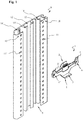
- Fig. 1 shows an exemplary embodiment of the shelf support 1 according to the invention and a corresponding, vertically standing shelf post 8, the shelf support 1 not yet being introduced into the shelf post 8.
- the shelf post 8 has a vertically running undercut 9 which is formed by two side walls 10, 10 '.
- the side cheeks 10, 10 ' include a plurality of openings 11, 11', which, along the vertical axis of the shelf post 8, regularly extending Have arrangement pattern.
- the shelf post 8 comprises a number of webs 13, 13', 14, 14 ', in particular a vertically extending stop element 12, which is arranged as an inner undercut, arranged within the shelf post 8, with two guide webs 13, 13 ', is formed.
- the shelf support 1, which is in the Figs. 2 to 4 is shown from different perspectives comprises, on the side facing the shelf post 8, the back of the shelf support 1, a spring element 2 in the center. On the side facing away from the shelf post 8, the front of the shelf support 1, a support 4 is formed.
- the support 4 has an elevation 5 which is used to grip into a corresponding recess of an object to be attached to it, in particular a shelf or a container.
- the distance between the knobs 3, 3 ' corresponds to the distance between two openings 11, 11' arranged at the same height, the complementary locking elements, of the shelf post 8.
- the shelf support 1 each has a bore 6, 6' .
- the distance between a knob 3, 3 'and the bore 6, 6' arranged below it corresponds to the distance between two adjacent openings 11, 11 'of a side wall 10, 10'.
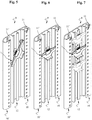
- FIG Fig. 5 The introduction of the shelf support 1 into the undercut 9 of the shelf support 8 formed by the side walls 10, 10 'is shown in FIG Fig. 5 shown.
- the shelf support 1 is inserted into the undercut 9 through an inclined position in relation to the vertically arranged shelf post 8, the spring element 2 being pressed against the stop element 12.
- the shelf support 1 is then inserted into the in Fig. 6 shown holding position rotated. Due to the action of the spring element 2 against the stop element 12, the shelf support 1 is pressed against the side walls 10, 10 'of the undercut 9, the knobs 3, 3' arranged on the front of the shelf support latching with the openings 11, 11 '.
- the shelf support 1 is removed from the undercut 9 of the shelf post 8 in the reverse order.
- FIG Fig. 7 The change in position of the shelf support 1 introduced into the shelf post 8 is shown in FIG Fig. 7 shown.
- the shelf support 1 is pressed against the stop element 12 by applying an external force, as a result of which the knobs 3, 3 'that are locked into the openings 11, 11' are released. While maintaining the external force, the position of the shelf support 1, as in the dashed representations of the Fig. 7 shown can be changed. Without the applied external force, the knobs 3, 3 'are locked again with the openings 11, 11'.
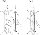
- the Figures 8 and 9 show a cross section through the shelf support 1 and the shelf post 8 and a cross section of the shelf support 1 introduced into the shelf post 8.
- the stop element 12 is limited by the two guide webs 13, 13 'in which the spring element 2 is guided.
- the spring element 2 In order to enable the rotation of the spring element 2 within the guide webs 13, 13 ', which is required for the described insertion and removal of the shelf support 1, the spring element 2 has rounded corners at two opposite corners, as is the case with the upper edge of the spring element 2 Fig. 2 is evident.
- the shelf post 8, as in FIG Fig. 9 is shown, two guide webs 14, 14 ', which are arranged in the region of the bores 6, 6' of the shelf support 1 introduced into the undercut 9.
- the guide webs 14, 14 ' serve to support the shelf support 1 in the area of the bores 6, 6' while screws are being inserted into the screw nuts arranged therein 7, 7 '.
- the distance between the guide webs 14, 14 'and a shelf support 1 introduced into the undercut 9 is selected so that the unlatching of the knobs 3, 3' that have snapped into the openings 11, 11 'and thus the insertion and removal of the shelf support 1 into the undercut 9 and the shifting of the shelf support 1 by the application of an external force is possible.
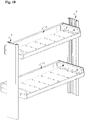
- FIG. 10 shows the attachment of insert parts in the form of containers 15 to shelf posts 8, via the shelf supports 1, which are not visible, is shown in FIG Fig. 10 and Fig. 11 shown.
- Fig. 10 shows the attachment of the container 15 to a shelf post 8.
- Two screws 16, 16 'are shown which are screwed through openings 11, 11' of the shelf post 8 into the screw nuts 7, 7 'of the shelf support 1.
- the screws 16, 16 ′ serve to additionally fix the container 15 to the shelf post 8.
Landscapes
- Warehouses Or Storage Devices (AREA)
- Passenger Equipment (AREA)
Description
- Die Erfindung betrifft einen Regalträger zum Einbringen in eine Hinterschneidung eines Regalpfostens, der nach dem Oberbegriff des Anspruchs 1 ausgebildet ist.
- Für die Befestigung von Regalböden oder Behältern an einem Regalpfosten sind Regalträger bekannt, wie beispielsweise aus den Druckschriften
DE 93 12 721 U1 undEP 2 084 990 B1 , die mit dem Regalpfosten über Schraub- oder Steckverbindungen verbunden sind. An Auflage- oder Verbindungselementen des am Pfosten befestigten Regalträgers können beispielsweise Regalböden oder Behälter angebracht werden. Die Position des Regalträgers am Regalpfosten ist dabei in Abhängigkeit von der vorgesehenen Bestückung des Regals einzustellen. Bei einer Änderung der Bestückung des Regals ist es oftmals erforderlich die Position der Regalträger zu ändern. - Für zahlreiche Anwendungsbereiche, beispielsweise für Regalsysteme die in ein Fahrzeug eingebracht werden, ist es vorteilhaft, den Regalträger in eine Hinterschneidung des Regalpfostens einzubringen und dort zu führen. Die Positionierung, insbesondere die Positionsänderung und Fixierung der Regalträger an dem Regalpfosten, ist dabei oftmals aufwendig, insbesondere bei Regalträgern die mit dem Regalpfosten verschraubt werden müssen. Trägerelemente zum Verbinden von Elementen mit einem Pfosten, wobei die Trägerelemente in den Pfosten, insbesondere in eine Hinterschneidung des Pfostens bzw. eines Profils, eingebracht werden, gehen beispielsweise aus der deutschen Patentanmeldung
DE 10 2008 019 671 A1 hervor. Hierbei werden Nutensteine zum Verbinden eines ersten Profils mit einem Gegenstand offenbart, die in das Profil eingebracht und dort positioniert werden. Um die Positionierung des Nutensteins zu erleichtern und ein Verrutschen des Nutensteins vor der Fixierung zu unterbinden, weist der Nutenstein ein gegen das Profil wirkendes Federelement auf, das den Nutenstein gegen das Profil vorspannt. Eine Positionsänderung der lediglich vorgespannten und nicht fixierten Nutensteine ist dabei unter geringem Kraftaufwand möglich. Die lasttragende Fixierung des Nutensteins erfolgt über das Verschrauben des anzubringenden Gegenstands mit einer Gewindebohrung des Nutensteins, wobei eine Klemmung der Seitenwangen, die die Hinterschneidung des Profils bilden, erfolgt. Nachteilig bei dieser Ausgestaltung ist, dass die Fixierung des Trägerelements in Form des Nutensteins über die Verschraubung mit dem außerhalb des Profils anzubringenden Gegenstand erfolgt. - Aus den Druckschriften
US 5 154 385 A1 ,US 10 130 178 B1 US 2 737 268 A sind in eine Hinterschneidung eines Regalpfostens einbringbare Trägerelemente mit einem auf der Rückseite angeordneten Federelement sowie auf der Vorderseite angeordneten Rastelementen zum Verrasten mit einem komplementären Rastelement des Regalpfostens bekannt. - Weitere Regalträger zum Einbringen in einen Regalpfosten gehen aus dem deutschen Patent
DE 43 02 147 C2 , der europäischen PatentanmeldungEP 1 665 954 A1 und der französischen PatentanmeldungFR 1 264 653 A - Aufgabe der Erfindung ist es, einen in einen Regalpfosten einbringbaren Regalträger bereitzustellen, der eine einfache Positionierung und sichere Fixierung des Regalträgers ermöglicht.
- Die Erfindung löst die Aufgabe durch einen Regalträger zum Einbringen in eine Hinterschneidung eines Regalpfostens mit den Merkmalen des Anspruchs 1. Zweckmäßige Ausgestaltungen und vorteilhafte Weiterbildungen der Erfindung sind in den Unteransprüchen angegeben.
- Der eingangs genannte Regalträger zum Einbringen in eine Hinterschneidung eines Regalpfostens, mit einem auf der dem Regalpfosten zugewandten Rückseite angeordneten Federelement, gegen dessen Wirkung der Regalträger in der Hinterschneidung festlegbar ist, weist auf der dem Regalpfosten abgewandten Vorderseite mindestens ein Rastelement auf, das, unter der Wirkung des Federelements, mit einem komplementären Rastelement des Regalpfostens verrastbar ist. Aus der beschriebenen Verrastung der Rastelemente resultiert eine belastbare Befestigung des Regalträgers am Regalpfosten. Eine zusätzliche Fixierung, insbesondere eine zusätzliche Verschraubung des Regalträgers mit dem Regalpfosten, ist dabei nicht zwingend erforderlich. Durch Aufbringen einer gegen die Feder gerichteten Kraft erfolgt dabei ein Entrasten der Rastelemente, wodurch die Änderung der Position des Regalträgers innerhalb des Regalpfostens möglich ist. Ohne die gegen die Wirkung des Federelements aufgebrachte Kraft erfolgt ein erneutes Verrasten des Regalträgers mit dem Regalpfosten.
- Weiter umfasst der Regalträger mindestens eine Bohrung, wobei die mindestens eine Bohrung dabei ein Gewinde aufweist. Um die Herstellung zu vereinfachen und eine stabile Befestigungsmöglichkeit zu schaffen, ist das Gewinde dabei durch eine in die Bohrung eingebrachte Schraubenmutter gebildet. Die Bohrung, insbesondere die mit einem Gewinde versehene Bohrung, ermöglicht eine zusätzliche Fixierung des Regalträgers oder die Fixierung eines Einsatzteils, beispielsweise eines Behälters, an dem Regalpfosten. Dies ist insbesondere bei einer hohen Belastung des Regalträgers oder des Einsatzteils, beispielsweise bei einer Beladung eines Regalbodens oder eines Behälters durch schwere Lasten, vorteilhaft. Bevorzugt ist die oder jede Bohrung des im Regalpfosten verrasteten Regalträgers bei einer Öffnung des Regalpfostens anordenbar.
- In einer vorteilhaften Ausgestaltung kann der Regalträger mindestens eine Auflage für ein Einsatzteil aufweisen. Die Auflage ist dabei auf der Vorderseite des Regalträgers angeordnet. Auf dieser Auflage können insbesondere Regalböden oder Behälter oder weitere, an dem Regalpfosten anzuordnende Gegenstände, angebracht werden. Dabei kann die Auflage auch weitere Verbindungselemente, insbesondere Erhöhungen oder Rastnasen aufweisen, die beispielsweise in eine Aussparung eines Regalbodens oder in den Boden eines Behälters eingreifen.
- Weiter kann das oder jedes Rastelement des Regalträgers eine Noppe und das komplementäre Rastelement des Regalpfostens eine Öffnung sein. Die Ausgestaltung des Rastelements des Regalträgers als Noppe, das in die Öffnung des Regalpfostens, eingreift, ermöglicht ein einfaches und effizientes Verrasten und Entrasten unter der Wirkung des Federelements. Die Öffnungen des Regalpfostens sind dabei vorteilhaft in einem regelmäßigen Muster an zwei Seitenwangen, die die Hinterschneidung des Regalpfostens bilden, angeordnet. Zweckmäßig umfassen die Seitenwangen dabei eine Vielzahl an Öffnungen, die die Positionierung des Regalträgers in der Hinterschneidung des Regalpfostens ermöglichen. Dadurch kann der Regalträger je nach Bedarf, insbesondere in Abhängigkeit von der vorgesehenen Bestückung des Regals, innerhalb des Regalpfostens positioniert werden.
- In einer vorteilhaften Ausgestaltung des Regalträgers kann das Federelement aus Kunststoff ausgebildet sein. Allerdings sind auch Federelemente aus einem anderen Material denkbar, beispielsweise eine Stahlfeder, die an dem Regalträger angebracht werden.
- Bevorzugt kann das Federelement des Regalträgers gegen ein Anschlagelement des Regalpfostens wirken. Das Anschlagelement kann dabei insbesondere zur Führung des Federelements ausgebildet sein.
- In einer bevorzugten Ausgestaltung kann der Regalträger aus Kunststoff ausgebildet sein. Dies ermöglicht eine einfache und kostengünstige Herstellung des Kunststoff-Regalträgers, beispielsweise durch ein 3D-Druck- oder ein Spritzgußverfahren.
- Die Erfindung wird nachfolgend anhand von Ausführungsbeispielen mit Bezug auf die begleitenden Zeichnungen detailliert beschrieben. Diese zeigen:
- Fig. 1
- eine Darstellung eines Regalträgers und eines Regalpfostens
- Fig. 2
- eine Darstellung des Regalträgers aus
Fig. 1 - Fig. 3
- eine Seitenansicht des Regalträgers aus
Fig. 1 - Fig. 4
- eine Draufsicht auf den Regalträger aus
Fig. 1 - Fig. 5
- das Einbringen des in
Fig. 1 gezeigten Regalträgers in den Regalpfosten - Fig. 6
- der in den Regalpfosten eingebrachte Regalträger aus
Fig. 5 - Fig. 7
- das Verschieben des in den Regalpfosten eingebrachten Regalträgers aus
Fig. 6 - Fig. 8
- einen Querschnitt durch den Regalträger und den Regalpfosten aus
Fig. 1 - Fig. 9
- einen Querschnitt durch den in den Regalpfosten eingebrachten Regalträger aus
Fig. 1 - Fig. 10
- zwei an Regalpfosten angebrachte Behälter
- Fig. 11
- eine Befestigung eines auf einem Regalträger angebrachten Behälter aus
Fig. 10 -
Fig. 1 zeigt ein Ausführungsbeispiel des erfindungsgemäßen Regalträgers 1 und eines dazu entsprechenden, vertikal stehenden Regalpfostens 8, wobei der Regalträger 1 noch nicht in den Regalpfosten 8 eingebracht ist. Der Regalpfosten 8 weist dabei eine vertikal verlaufende Hinterschneidung 9 auf, die durch zwei Seitenwangen 10, 10' gebildet wird. Die Seitenwangen 10, 10' umfassen dabei eine Vielzahl an Öffnungen 11, 11', die ein, entlang der vertikalen Achse des Regalpfostens 8, regelmäßig verlaufendes Anordnungsmuster aufweisen. Neben den Seitenwangen 10, 10' umfasst der Regalpfosten 8 eine Reihe von Stegen 13, 13', 14, 14', insbesondere ein vertikal verlaufendes Anschlagelement 12, das als eine, innerhalb des Regalpfostens 8 angeordnete, innere Hinterschneidung, mit zwei Führungsstegen 13, 13', ausgebildet ist. - Der Regalträger 1, der in den
Fig. 2 bis 4 aus verschiedenen Perspektiven dargestellt ist, umfasst, auf der dem Regalpfosten 8 zugewandten Seite, der Rückseite des Regalträgers 1, mittig ein Federelement 2. Auf der dem Regalpfosten 8 abgewandten Seite, der Vorderseite des Regalträgers 1, ist eine Auflage 4 ausgebildet. Die Auflage 4 weist dabei eine Erhöhung 5 auf, die dazu dient, in eine entsprechende Aussparung eines daran anzubringenden Gegenstands, insbesondere eines Regalbodens oder eines Behälters, zu greifen. - Auf der Vorderseite des Regalträgers 1 sind dabei, nahe der jeweiligen Querseite des Regalträgers 1, ein erstes Rastelement sowie ein zweites Rastelement, in Form einer kreuzförmigen Noppe 3, 3' angeordnet. Der Abstand der Noppen 3, 3' entspricht dabei dem Abstand zweier auf gleicher Höhe angeordneten Öffnungen 11, 11', den komplementären Rastelementen, des Regalpfostens 8. Unterhalb der Noppen 3, 3' weist der Regalträger 1 je eine Bohrung 6, 6'auf. Der Abstand einer Noppe 3, 3' und der darunter angeordneten Bohrung 6, 6' entspricht dabei dem Abstand zweier benachbarter Öffnungen 11, 11' einer Seitenwange 10, 10'. Allerdings sind auch Ausgestaltungen des Regalträgers denkbar, wobei der Abstand einer Noppe 3, 3' und der darunter angeordneten Bohrung 6, 6' einem Mehrfachen des Abstands zweier benachbarter Öffnungen 11, 11' entspricht. Die Bohrungen 6, 6' sind durch eingebrachte Schraubenmuttern 7, 7' mit einem Gewinde versehen.
- Die
Fig. 5 bis 7 zeigen das Einbringen, Befestigen sowie Positionieren des Regalträgers 1 an dem Regalpfosten 8, wobei, aus Gründen der Übersichtlichkeit, nicht alle Bezugszeichen eingezeichnet sind. - Das Einbringen des Regalträgers 1, in die durch die Seitenwangen 10, 10' gebildete Hinterschneidung 9 des Regalträgers 8, ist in
Fig. 5 gezeigt. Der Regalträger 1 wird dabei durch eine Schrägstellung, in Bezug auf den vertikal angeordneten Regalpfosten 8, in die Hinterschneidung 9 eingeführt, wobei das Federelement 2 gegen das Anschlagelement 12 gedrückt wird. Anschließend wird der Regalträger 1 in die inFig. 6 gezeigte Haltestellung gedreht. Durch die Wirkung des Federelements 2 gegen das Anschlagelement 12 wird der Regalträger 1 gegen die Seitenwangen 10, 10' der Hinterschneidung 9 gedrückt, wobei die auf der Vorderseite des Regalträgers angeordneten Noppen 3, 3' mit den Öffnungen 11, 11' verrasten. Das Ausbringen des Regalträgers 1 aus der Hinterschneidung 9 des Regalpfostens 8 erfolgt dabei in umgekehrter Reihenfolge. - Die Positionsänderung des in den Regalpfosten 8 eingebrachten Regalträgers 1, ist in
Fig. 7 gezeigt. Hierfür wird der Regalträger 1, durch Aufbringen einer äußeren Kraft, gegen das Anschlagelement 12 gedrückt, wodurch ein Entrasten, der in die Öffnungen 11, 11' eingerasteten Noppen 3, 3', erfolgt. Unter Aufrechterhaltung der äußeren Kraft kann die Position des Regalträgers 1, wie in den gestrichelten Darstellungen derFig. 7 gezeigt ist, geändert werden. Ohne die aufgebrachte äußere Kraft erfolgt das erneute Verrasten der Noppen 3, 3' mit den Öffnungen 11, 11'. - Die
Fig. 8 und 9 zeigen einen Querschnitt durch den Regalträger 1 und den Regalpfosten 8 sowie einen Querschnitt des in den Regalpfosten 8 eingebrachten Regalträgers 1. Das Anschlagelement 12 wird dabei durch die zwei Führungsstege 13, 13' begrenzt, in denen das Federelement 2 geführt wird. Um das Drehen des Federelements 2 innerhalb der Führungsstege 13, 13', das für das beschriebene Ein- und Ausbringen des Regalträgers 1 erforderlich ist, zu ermöglichen, weist das Federelement 2 Abrundungen zweier gegenüberliegender Ecken auf, wie bei der Oberkante des Federelements 2 ausFig. 2 ersichtlicht ist. - Innerhalb der Hinterschneidung 9 weist der Regalpfosten 8, wie in
Fig. 9 gezeigt ist, zwei Leitstege 14, 14' auf, die im Bereich der Bohrungen 6, 6' des in die Hinterschneidung 9 eingebrachten Regalträgers 1 angeordnet sind. Die Leitstege 14, 14' dienen dabei zur Abstützung des Regalträgers 1 im Bereich der Bohrungen 6, 6' während eines Einbringens von Schrauben in die darin angeordneten Schraubenmuttern 7, 7'. Der Abstand zwischen den Leitstegen 14, 14' und einem in die Hinterschneidung 9 eingebrachten Regalträger 1 ist dabei so gewählt, dass das Entrasten der in die Öffnungen 11, 11' eingerasteten Noppen 3, 3' und somit das Ein- und Ausbringen des Regalträgers 1 in die Hinterschneidung 9 sowie das Verschieben des Regalträgers 1 durch das Aufbringen einer äußeren Kraft möglich ist. - Die Anbringung von Einsatzteilen in Form von Behältern 15 an Regalpfosten 8, über die nicht sichtbaren Regalträger 1, ist in
Fig. 10 undFig. 11 gezeigt.Fig. 10 zeigt dabei die Befestigung des Behälters 15 an einem Regalpfosten 8. Dabei sind zwei Schrauben 16, 16' dargestellt, die durch Öffnungen 11, 11' des Regalpfostens 8 in die Schraubenmuttern 7, 7', des Regalträgers 1 eingeschraubt sind. Die Schrauben 16, 16' dienen dabei, neben dem Anbringen des Behälters 15 auf der Auflage 4 des Regalträgers 1, zu einer zusätzlichen Fixierung des Behälters 15 am Regalpfosten 8. -
- 1
- Regalträger
- 2
- Federelement
- 3, 3'
- Noppe
- 4
- Auflage
- 5
- Erhöhung
- 6, 6'
- Bohrung
- 7,7'
- Schraubenmutter
- 8
- Regalpfosten
- 9
- Hinterschneidung
- 10, 10'
- Seitenwangen
- 11, 11'
- Öffnung
- 12
- Anschlagelement
- 13, 13'
- Führungssteg
- 14, 14'
- Leitsteg
- 15
- Behälter
- 16
- Schrauben
Claims (7)
- Regalträger (1) zum Einbringen in eine Hinterschneidung (9) eines Regalpfostens (8), mit einem auf der dem Regalpfosten (8) zugewandten Rückseite angeordneten Federelement (2) gegen dessen Wirkung der Regalträger (1) in der Hinterschneidung (9) festlegbar ist, wobei der Regalträger (1) auf der dem Regalpfosten (8) abgewandten Vorderseite mindestens ein Rastelement aufweist, das unter der Wirkung des Federelements (2) mit einem komplementären Rastelement des Regalpfostens (8) verrastbar ist, wobei der Regalträger (1) mindestens eine Bohrung (6) umfasst, dadurch gekennzeichnet, dass in der oder jeder Bohrung (6) eine Schraubenmutter angeordnet ist.
- Regalträger (1) nach Anspruch 1, dadurch gekennzeichnet, dass das der Regalträger (1) mindestens eine Auflage (4) für ein Einsatzteil (14) aufweist.
- Regalträger (1) nach einem der voranstehenden Ansprüche, dadurch gekennzeichnet, dass das oder jedes Rastelement des Regalträgers (1) eine Noppe (3) und das komplementäre Rastelement des Regalpfostens (8) eine Öffnung (11) ist.
- Regalträger (1) nach Anspruch einem der voranstehenden Ansprüche, dadurch gekennzeichnet, dass die oder jede Bohrung (6) des im Regalpfosten (8) verrasteten Regalträgers (1) bei einer Öffnung (11) des Regalpfostens (8) anordenbar ist.
- Regalträger (1) nach einem der voranstehenden Ansprüche, dadurch gekennzeichnet, dass das Federelement (2) aus Kunststoff ist.
- Regalträger (1) nach einem der voranstehenden Ansprüche, dadurch gekennzeichnet, dass das Federelement (2) gegen ein Anschlagelement (12) des Regalpfostens (8) wirken kann.
- Regalträger (1) nach einem der voranstehenden Ansprüche, dadurch gekennzeichnet, dass der Regalträger (1) aus Kunststoff ist.
Applications Claiming Priority (1)
| Application Number | Priority Date | Filing Date | Title |
|---|---|---|---|
| DE102018112062.1A DE102018112062A1 (de) | 2018-05-18 | 2018-05-18 | Regalträger zum Einbringen in eine Hinterschneidung eines Regalpfostens |
Publications (2)
| Publication Number | Publication Date |
|---|---|
| EP3569101A1 EP3569101A1 (de) | 2019-11-20 |
| EP3569101B1 true EP3569101B1 (de) | 2021-11-10 |
Family
ID=66323764
Family Applications (1)
| Application Number | Title | Priority Date | Filing Date |
|---|---|---|---|
| EP19171603.4A Active EP3569101B1 (de) | 2018-05-18 | 2019-04-29 | Regalträger zum einbringen in eine hinterschneidung eines regalpfostens |
Country Status (3)
| Country | Link |
|---|---|
| EP (1) | EP3569101B1 (de) |
| DE (1) | DE102018112062A1 (de) |
| DK (1) | DK3569101T3 (de) |
Families Citing this family (3)
| Publication number | Priority date | Publication date | Assignee | Title |
|---|---|---|---|---|
| TWI813207B (zh) * | 2022-03-16 | 2023-08-21 | 葉華婷 | 旋轉卡合固定裝置 |
| CA3254819A1 (en) | 2022-07-11 | 2024-01-18 | Milwaukee Electric Tool Corporation | MOBILE STORAGE FOR MODULAR SYSTEMS |
| GB2629197A (en) * | 2023-04-20 | 2024-10-23 | Yoke Cnc Ltd | Storage system |
Family Cites Families (6)
| Publication number | Priority date | Publication date | Assignee | Title |
|---|---|---|---|---|
| NL82706C (de) * | 1951-04-03 | |||
| FR1264653A (fr) * | 1960-05-13 | 1961-06-23 | Installations Generales Et D A | Console plus particulièrement destinée à supporter des étagères |
| US5154385A (en) * | 1991-04-08 | 1992-10-13 | George R. Todd | Support systems with improved channel nuts |
| DE9217491U1 (de) * | 1992-12-22 | 1993-02-25 | Krause, Bernd, 6454 Bruchköbel | Trägeranordnung für Lasten |
| EP1665954A1 (de) * | 2004-12-02 | 2006-06-07 | Brinkmann Wolfgang | Präsentationsvorrichtung |
| US10130178B1 (en) * | 2015-02-09 | 2018-11-20 | Mark James Landes | Rail mount systems |
-
2018
- 2018-05-18 DE DE102018112062.1A patent/DE102018112062A1/de not_active Withdrawn
-
2019
- 2019-04-29 DK DK19171603.4T patent/DK3569101T3/da active
- 2019-04-29 EP EP19171603.4A patent/EP3569101B1/de active Active
Non-Patent Citations (1)
| Title |
|---|
| None * |
Also Published As
| Publication number | Publication date |
|---|---|
| DK3569101T3 (da) | 2021-12-13 |
| EP3569101A1 (de) | 2019-11-20 |
| DE102018112062A1 (de) | 2019-11-21 |
Similar Documents
| Publication | Publication Date | Title |
|---|---|---|
| EP0935076B1 (de) | Befestigungsvorrichtung für die Befestigung mehrerer Möbelbeschläge an einem Möbelteil | |
| AT392884B (de) | Moebelverbinder | |
| EP2389836B1 (de) | Verkaufsregal | |
| EP0567844B1 (de) | Schliessanlage für Schubladenschränke | |
| EP3569101A1 (de) | Regalträger zum einbringen in eine hinterschneidung eines regalpfostens | |
| DE102012007771B4 (de) | Montageplattenhalter für einen Schaltschrank sowie ein Befestigungsmittel zur Verwendung bei diesem | |
| DE202018102792U1 (de) | Regalträger zum Einbringen in eine Hinterschneidung eines Regalpfostens | |
| EP4223180B1 (de) | Regalsystem | |
| DE102017110766A1 (de) | Befestigungsset zum Befestigen eines Montagegestells für Sanitärobjekte und Verwendung eines solchen Befestigungssets | |
| DE102007009667B4 (de) | Profilkonstruktion | |
| EP0894064A1 (de) | Transportvorrichtung | |
| DE202020104417U1 (de) | Auszugssperre | |
| EP0645281A1 (de) | Stützfuss für ein Relingrohr einer auf einem Kraftfahrzeug anzuordnenden Dachreling | |
| DE202010004220U1 (de) | Regalsystem | |
| DE202012104771U1 (de) | Profilverbinder | |
| DE10303331B3 (de) | Mittels einer Bodenführung an oder in einer Bodenführungsschiene zwangsgeführtes Trennwandelement | |
| EP2465379B1 (de) | Schrank, insbesondere Spiegelschrank | |
| CH720967A2 (de) | Verbinder für Leiterrahmen | |
| DE202023102174U1 (de) | Haltevorrichtung zur Anbringung eines Einsatzteils an einem Regalpfosten sowie Regalpfosten zur Anbringung eines Einsatzteils an diesem | |
| WO2018028844A1 (de) | Profilbauteil und möbelsystem mit einem solchen profilbauteil | |
| DE102016119857B4 (de) | Werkzeugcontainer und Verfahren zur Herstellung eines Werkzeugcontainers | |
| DE9313959U1 (de) | Vorrichtung zur Festsetzung einer geöffneten Tür o.dgl. | |
| EP1943925A1 (de) | Vorrichtung zum Befestigen von Tablaren | |
| CH722127B1 (de) | Modulares, mehrfach montierbares und demontierbares Gestellsystem | |
| DE19829685A1 (de) | Kastenmöbelstück mit Tragleisten |
Legal Events
| Date | Code | Title | Description |
|---|---|---|---|
| PUAI | Public reference made under article 153(3) epc to a published international application that has entered the european phase |
Free format text: ORIGINAL CODE: 0009012 |
|
| STAA | Information on the status of an ep patent application or granted ep patent |
Free format text: STATUS: THE APPLICATION HAS BEEN PUBLISHED |
|
| AK | Designated contracting states |
Kind code of ref document: A1 Designated state(s): AL AT BE BG CH CY CZ DE DK EE ES FI FR GB GR HR HU IE IS IT LI LT LU LV MC MK MT NL NO PL PT RO RS SE SI SK SM TR |
|
| AX | Request for extension of the european patent |
Extension state: BA ME |
|
| STAA | Information on the status of an ep patent application or granted ep patent |
Free format text: STATUS: REQUEST FOR EXAMINATION WAS MADE |
|
| 17P | Request for examination filed |
Effective date: 20200520 |
|
| RBV | Designated contracting states (corrected) |
Designated state(s): AL AT BE BG CH CY CZ DE DK EE ES FI FR GB GR HR HU IE IS IT LI LT LU LV MC MK MT NL NO PL PT RO RS SE SI SK SM TR |
|
| STAA | Information on the status of an ep patent application or granted ep patent |
Free format text: STATUS: EXAMINATION IS IN PROGRESS |
|
| 17Q | First examination report despatched |
Effective date: 20200702 |
|
| GRAP | Despatch of communication of intention to grant a patent |
Free format text: ORIGINAL CODE: EPIDOSNIGR1 |
|
| STAA | Information on the status of an ep patent application or granted ep patent |
Free format text: STATUS: GRANT OF PATENT IS INTENDED |
|
| INTG | Intention to grant announced |
Effective date: 20210709 |
|
| GRAS | Grant fee paid |
Free format text: ORIGINAL CODE: EPIDOSNIGR3 |
|
| GRAA | (expected) grant |
Free format text: ORIGINAL CODE: 0009210 |
|
| STAA | Information on the status of an ep patent application or granted ep patent |
Free format text: STATUS: THE PATENT HAS BEEN GRANTED |
|
| AK | Designated contracting states |
Kind code of ref document: B1 Designated state(s): AL AT BE BG CH CY CZ DE DK EE ES FI FR GB GR HR HU IE IS IT LI LT LU LV MC MK MT NL NO PL PT RO RS SE SI SK SM TR |
|
| REG | Reference to a national code |
Ref country code: GB Ref legal event code: FG4D Free format text: NOT ENGLISH |
|
| REG | Reference to a national code |
Ref country code: AT Ref legal event code: REF Ref document number: 1445259 Country of ref document: AT Kind code of ref document: T Effective date: 20211115 Ref country code: CH Ref legal event code: EP |
|
| REG | Reference to a national code |
Ref country code: DE Ref legal event code: R096 Ref document number: 502019002677 Country of ref document: DE |
|
| REG | Reference to a national code |
Ref country code: IE Ref legal event code: FG4D Free format text: LANGUAGE OF EP DOCUMENT: GERMAN |
|
| REG | Reference to a national code |
Ref country code: DK Ref legal event code: T3 Effective date: 20211206 |
|
| REG | Reference to a national code |
Ref country code: NL Ref legal event code: FP |
|
| REG | Reference to a national code |
Ref country code: LT Ref legal event code: MG9D |
|
| PG25 | Lapsed in a contracting state [announced via postgrant information from national office to epo] |
Ref country code: RS Free format text: LAPSE BECAUSE OF FAILURE TO SUBMIT A TRANSLATION OF THE DESCRIPTION OR TO PAY THE FEE WITHIN THE PRESCRIBED TIME-LIMIT Effective date: 20211110 Ref country code: LT Free format text: LAPSE BECAUSE OF FAILURE TO SUBMIT A TRANSLATION OF THE DESCRIPTION OR TO PAY THE FEE WITHIN THE PRESCRIBED TIME-LIMIT Effective date: 20211110 Ref country code: FI Free format text: LAPSE BECAUSE OF FAILURE TO SUBMIT A TRANSLATION OF THE DESCRIPTION OR TO PAY THE FEE WITHIN THE PRESCRIBED TIME-LIMIT Effective date: 20211110 Ref country code: BG Free format text: LAPSE BECAUSE OF FAILURE TO SUBMIT A TRANSLATION OF THE DESCRIPTION OR TO PAY THE FEE WITHIN THE PRESCRIBED TIME-LIMIT Effective date: 20220210 |
|
| PG25 | Lapsed in a contracting state [announced via postgrant information from national office to epo] |
Ref country code: IS Free format text: LAPSE BECAUSE OF FAILURE TO SUBMIT A TRANSLATION OF THE DESCRIPTION OR TO PAY THE FEE WITHIN THE PRESCRIBED TIME-LIMIT Effective date: 20220310 Ref country code: SE Free format text: LAPSE BECAUSE OF FAILURE TO SUBMIT A TRANSLATION OF THE DESCRIPTION OR TO PAY THE FEE WITHIN THE PRESCRIBED TIME-LIMIT Effective date: 20211110 Ref country code: PT Free format text: LAPSE BECAUSE OF FAILURE TO SUBMIT A TRANSLATION OF THE DESCRIPTION OR TO PAY THE FEE WITHIN THE PRESCRIBED TIME-LIMIT Effective date: 20220310 Ref country code: PL Free format text: LAPSE BECAUSE OF FAILURE TO SUBMIT A TRANSLATION OF THE DESCRIPTION OR TO PAY THE FEE WITHIN THE PRESCRIBED TIME-LIMIT Effective date: 20211110 Ref country code: NO Free format text: LAPSE BECAUSE OF FAILURE TO SUBMIT A TRANSLATION OF THE DESCRIPTION OR TO PAY THE FEE WITHIN THE PRESCRIBED TIME-LIMIT Effective date: 20220210 Ref country code: LV Free format text: LAPSE BECAUSE OF FAILURE TO SUBMIT A TRANSLATION OF THE DESCRIPTION OR TO PAY THE FEE WITHIN THE PRESCRIBED TIME-LIMIT Effective date: 20211110 Ref country code: HR Free format text: LAPSE BECAUSE OF FAILURE TO SUBMIT A TRANSLATION OF THE DESCRIPTION OR TO PAY THE FEE WITHIN THE PRESCRIBED TIME-LIMIT Effective date: 20211110 Ref country code: GR Free format text: LAPSE BECAUSE OF FAILURE TO SUBMIT A TRANSLATION OF THE DESCRIPTION OR TO PAY THE FEE WITHIN THE PRESCRIBED TIME-LIMIT Effective date: 20220211 Ref country code: ES Free format text: LAPSE BECAUSE OF FAILURE TO SUBMIT A TRANSLATION OF THE DESCRIPTION OR TO PAY THE FEE WITHIN THE PRESCRIBED TIME-LIMIT Effective date: 20211110 |
|
| PG25 | Lapsed in a contracting state [announced via postgrant information from national office to epo] |
Ref country code: SM Free format text: LAPSE BECAUSE OF FAILURE TO SUBMIT A TRANSLATION OF THE DESCRIPTION OR TO PAY THE FEE WITHIN THE PRESCRIBED TIME-LIMIT Effective date: 20211110 Ref country code: SK Free format text: LAPSE BECAUSE OF FAILURE TO SUBMIT A TRANSLATION OF THE DESCRIPTION OR TO PAY THE FEE WITHIN THE PRESCRIBED TIME-LIMIT Effective date: 20211110 Ref country code: RO Free format text: LAPSE BECAUSE OF FAILURE TO SUBMIT A TRANSLATION OF THE DESCRIPTION OR TO PAY THE FEE WITHIN THE PRESCRIBED TIME-LIMIT Effective date: 20211110 Ref country code: EE Free format text: LAPSE BECAUSE OF FAILURE TO SUBMIT A TRANSLATION OF THE DESCRIPTION OR TO PAY THE FEE WITHIN THE PRESCRIBED TIME-LIMIT Effective date: 20211110 Ref country code: CZ Free format text: LAPSE BECAUSE OF FAILURE TO SUBMIT A TRANSLATION OF THE DESCRIPTION OR TO PAY THE FEE WITHIN THE PRESCRIBED TIME-LIMIT Effective date: 20211110 |
|
| REG | Reference to a national code |
Ref country code: DE Ref legal event code: R097 Ref document number: 502019002677 Country of ref document: DE |
|
| PLBE | No opposition filed within time limit |
Free format text: ORIGINAL CODE: 0009261 |
|
| STAA | Information on the status of an ep patent application or granted ep patent |
Free format text: STATUS: NO OPPOSITION FILED WITHIN TIME LIMIT |
|
| 26N | No opposition filed |
Effective date: 20220811 |
|
| PG25 | Lapsed in a contracting state [announced via postgrant information from national office to epo] |
Ref country code: AL Free format text: LAPSE BECAUSE OF FAILURE TO SUBMIT A TRANSLATION OF THE DESCRIPTION OR TO PAY THE FEE WITHIN THE PRESCRIBED TIME-LIMIT Effective date: 20211110 |
|
| PG25 | Lapsed in a contracting state [announced via postgrant information from national office to epo] |
Ref country code: SI Free format text: LAPSE BECAUSE OF FAILURE TO SUBMIT A TRANSLATION OF THE DESCRIPTION OR TO PAY THE FEE WITHIN THE PRESCRIBED TIME-LIMIT Effective date: 20211110 |
|
| REG | Reference to a national code |
Ref country code: CH Ref legal event code: PL |
|
| REG | Reference to a national code |
Ref country code: BE Ref legal event code: MM Effective date: 20220430 |
|
| PG25 | Lapsed in a contracting state [announced via postgrant information from national office to epo] |
Ref country code: MC Free format text: LAPSE BECAUSE OF FAILURE TO SUBMIT A TRANSLATION OF THE DESCRIPTION OR TO PAY THE FEE WITHIN THE PRESCRIBED TIME-LIMIT Effective date: 20211110 Ref country code: LU Free format text: LAPSE BECAUSE OF NON-PAYMENT OF DUE FEES Effective date: 20220429 Ref country code: LI Free format text: LAPSE BECAUSE OF NON-PAYMENT OF DUE FEES Effective date: 20220430 Ref country code: CH Free format text: LAPSE BECAUSE OF NON-PAYMENT OF DUE FEES Effective date: 20220430 |
|
| PG25 | Lapsed in a contracting state [announced via postgrant information from national office to epo] |
Ref country code: BE Free format text: LAPSE BECAUSE OF NON-PAYMENT OF DUE FEES Effective date: 20220430 |
|
| PG25 | Lapsed in a contracting state [announced via postgrant information from national office to epo] |
Ref country code: IE Free format text: LAPSE BECAUSE OF NON-PAYMENT OF DUE FEES Effective date: 20220429 |
|
| PG25 | Lapsed in a contracting state [announced via postgrant information from national office to epo] |
Ref country code: HU Free format text: LAPSE BECAUSE OF FAILURE TO SUBMIT A TRANSLATION OF THE DESCRIPTION OR TO PAY THE FEE WITHIN THE PRESCRIBED TIME-LIMIT; INVALID AB INITIO Effective date: 20190429 |
|
| PG25 | Lapsed in a contracting state [announced via postgrant information from national office to epo] |
Ref country code: MK Free format text: LAPSE BECAUSE OF FAILURE TO SUBMIT A TRANSLATION OF THE DESCRIPTION OR TO PAY THE FEE WITHIN THE PRESCRIBED TIME-LIMIT Effective date: 20211110 Ref country code: CY Free format text: LAPSE BECAUSE OF FAILURE TO SUBMIT A TRANSLATION OF THE DESCRIPTION OR TO PAY THE FEE WITHIN THE PRESCRIBED TIME-LIMIT Effective date: 20211110 |
|
| PG25 | Lapsed in a contracting state [announced via postgrant information from national office to epo] |
Ref country code: TR Free format text: LAPSE BECAUSE OF FAILURE TO SUBMIT A TRANSLATION OF THE DESCRIPTION OR TO PAY THE FEE WITHIN THE PRESCRIBED TIME-LIMIT Effective date: 20211110 |
|
| PG25 | Lapsed in a contracting state [announced via postgrant information from national office to epo] |
Ref country code: MT Free format text: LAPSE BECAUSE OF FAILURE TO SUBMIT A TRANSLATION OF THE DESCRIPTION OR TO PAY THE FEE WITHIN THE PRESCRIBED TIME-LIMIT Effective date: 20211110 |
|
| PGFP | Annual fee paid to national office [announced via postgrant information from national office to epo] |
Ref country code: NL Payment date: 20250422 Year of fee payment: 7 |
|
| PGFP | Annual fee paid to national office [announced via postgrant information from national office to epo] |
Ref country code: DE Payment date: 20250509 Year of fee payment: 7 |
|
| PGFP | Annual fee paid to national office [announced via postgrant information from national office to epo] |
Ref country code: DK Payment date: 20250423 Year of fee payment: 7 |
|
| PGFP | Annual fee paid to national office [announced via postgrant information from national office to epo] |
Ref country code: IT Payment date: 20250430 Year of fee payment: 7 |
|
| PGFP | Annual fee paid to national office [announced via postgrant information from national office to epo] |
Ref country code: FR Payment date: 20250422 Year of fee payment: 7 |
|
| PGFP | Annual fee paid to national office [announced via postgrant information from national office to epo] |
Ref country code: AT Payment date: 20250416 Year of fee payment: 7 |
|
| PGFP | Annual fee paid to national office [announced via postgrant information from national office to epo] |
Ref country code: GB Payment date: 20260324 Year of fee payment: 8 |