EP3568356B1 - Carton with top closure - Google Patents
Carton with top closure Download PDFInfo
- Publication number
- EP3568356B1 EP3568356B1 EP18739407.7A EP18739407A EP3568356B1 EP 3568356 B1 EP3568356 B1 EP 3568356B1 EP 18739407 A EP18739407 A EP 18739407A EP 3568356 B1 EP3568356 B1 EP 3568356B1
- Authority
- EP
- European Patent Office
- Prior art keywords
- panel
- gusset
- end flap
- foldably connected
- carton
- Prior art date
- Legal status (The legal status is an assumption and is not a legal conclusion. Google has not performed a legal analysis and makes no representation as to the accuracy of the status listed.)
- Active
Links
- 238000000034 method Methods 0.000 claims description 11
- 239000000463 material Substances 0.000 description 13
- 235000013305 food Nutrition 0.000 description 8
- 239000000853 adhesive Substances 0.000 description 6
- 230000001070 adhesive effect Effects 0.000 description 6
- 230000009969 flowable effect Effects 0.000 description 6
- 239000003292 glue Substances 0.000 description 6
- 230000004913 activation Effects 0.000 description 4
- 238000004806 packaging method and process Methods 0.000 description 3
- 230000037361 pathway Effects 0.000 description 3
- 230000015572 biosynthetic process Effects 0.000 description 2
- 239000004927 clay Substances 0.000 description 2
- 239000011248 coating agent Substances 0.000 description 2
- 238000000576 coating method Methods 0.000 description 2
- 239000000123 paper Substances 0.000 description 2
- 239000011087 paperboard Substances 0.000 description 2
- 238000007789 sealing Methods 0.000 description 2
- VRDIULHPQTYCLN-UHFFFAOYSA-N Prothionamide Chemical group CCCC1=CC(C(N)=S)=CC=N1 VRDIULHPQTYCLN-UHFFFAOYSA-N 0.000 description 1
- 230000003213 activating effect Effects 0.000 description 1
- 238000007792 addition Methods 0.000 description 1
- WYTGDNHDOZPMIW-RCBQFDQVSA-N alstonine Natural products C1=CC2=C3C=CC=CC3=NC2=C2N1C[C@H]1[C@H](C)OC=C(C(=O)OC)[C@H]1C2 WYTGDNHDOZPMIW-RCBQFDQVSA-N 0.000 description 1
- 230000004888 barrier function Effects 0.000 description 1
- 230000008901 benefit Effects 0.000 description 1
- 235000013361 beverage Nutrition 0.000 description 1
- 239000011111 cardboard Substances 0.000 description 1
- 235000013339 cereals Nutrition 0.000 description 1
- 235000009508 confectionery Nutrition 0.000 description 1
- 239000002537 cosmetic Substances 0.000 description 1
- 235000013365 dairy product Nutrition 0.000 description 1
- 239000003599 detergent Substances 0.000 description 1
- 235000014168 granola/muesli bars Nutrition 0.000 description 1
- 239000007788 liquid Substances 0.000 description 1
- 230000004048 modification Effects 0.000 description 1
- 238000012986 modification Methods 0.000 description 1
- 235000015927 pasta Nutrition 0.000 description 1
- 239000002966 varnish Substances 0.000 description 1
- 230000003313 weakening effect Effects 0.000 description 1
Images


Classifications
-
- B—PERFORMING OPERATIONS; TRANSPORTING
- B65—CONVEYING; PACKING; STORING; HANDLING THIN OR FILAMENTARY MATERIAL
- B65D—CONTAINERS FOR STORAGE OR TRANSPORT OF ARTICLES OR MATERIALS, e.g. BAGS, BARRELS, BOTTLES, BOXES, CANS, CARTONS, CRATES, DRUMS, JARS, TANKS, HOPPERS, FORWARDING CONTAINERS; ACCESSORIES, CLOSURES, OR FITTINGS THEREFOR; PACKAGING ELEMENTS; PACKAGES
- B65D5/00—Rigid or semi-rigid containers of polygonal cross-section, e.g. boxes, cartons or trays, formed by folding or erecting one or more blanks made of paper
- B65D5/02—Rigid or semi-rigid containers of polygonal cross-section, e.g. boxes, cartons or trays, formed by folding or erecting one or more blanks made of paper by folding or erecting a single blank to form a tubular body with or without subsequent folding operations, or the addition of separate elements, to close the ends of the body
- B65D5/06—Rigid or semi-rigid containers of polygonal cross-section, e.g. boxes, cartons or trays, formed by folding or erecting one or more blanks made of paper by folding or erecting a single blank to form a tubular body with or without subsequent folding operations, or the addition of separate elements, to close the ends of the body with end-closing or contents-supporting elements formed by folding inwardly a wall extending from, and continuously around, an end of the tubular body
- B65D5/061—Rectangular containers having a body with gusset-flaps folded inwardly beneath the closure flaps
-
- B—PERFORMING OPERATIONS; TRANSPORTING
- B65—CONVEYING; PACKING; STORING; HANDLING THIN OR FILAMENTARY MATERIAL
- B65D—CONTAINERS FOR STORAGE OR TRANSPORT OF ARTICLES OR MATERIALS, e.g. BAGS, BARRELS, BOTTLES, BOXES, CANS, CARTONS, CRATES, DRUMS, JARS, TANKS, HOPPERS, FORWARDING CONTAINERS; ACCESSORIES, CLOSURES, OR FITTINGS THEREFOR; PACKAGING ELEMENTS; PACKAGES
- B65D5/00—Rigid or semi-rigid containers of polygonal cross-section, e.g. boxes, cartons or trays, formed by folding or erecting one or more blanks made of paper
- B65D5/02—Rigid or semi-rigid containers of polygonal cross-section, e.g. boxes, cartons or trays, formed by folding or erecting one or more blanks made of paper by folding or erecting a single blank to form a tubular body with or without subsequent folding operations, or the addition of separate elements, to close the ends of the body
- B65D5/0227—Rigid or semi-rigid containers of polygonal cross-section, e.g. boxes, cartons or trays, formed by folding or erecting one or more blanks made of paper by folding or erecting a single blank to form a tubular body with or without subsequent folding operations, or the addition of separate elements, to close the ends of the body with end closures formed by inward folding of flaps and securing them by heat-sealing, by applying adhesive to the flaps or by staples
-
- B—PERFORMING OPERATIONS; TRANSPORTING
- B31—MAKING ARTICLES OF PAPER, CARDBOARD OR MATERIAL WORKED IN A MANNER ANALOGOUS TO PAPER; WORKING PAPER, CARDBOARD OR MATERIAL WORKED IN A MANNER ANALOGOUS TO PAPER
- B31B—MAKING CONTAINERS OF PAPER, CARDBOARD OR MATERIAL WORKED IN A MANNER ANALOGOUS TO PAPER
- B31B50/00—Making rigid or semi-rigid containers, e.g. boxes or cartons
- B31B50/26—Folding sheets, blanks or webs
- B31B50/262—Folding sheets, blanks or webs involving folding, leading, or trailing flaps of blanks
-
- B—PERFORMING OPERATIONS; TRANSPORTING
- B31—MAKING ARTICLES OF PAPER, CARDBOARD OR MATERIAL WORKED IN A MANNER ANALOGOUS TO PAPER; WORKING PAPER, CARDBOARD OR MATERIAL WORKED IN A MANNER ANALOGOUS TO PAPER
- B31B—MAKING CONTAINERS OF PAPER, CARDBOARD OR MATERIAL WORKED IN A MANNER ANALOGOUS TO PAPER
- B31B2100/00—Rigid or semi-rigid containers made by folding single-piece sheets, blanks or webs
- B31B2100/002—Rigid or semi-rigid containers made by folding single-piece sheets, blanks or webs characterised by the shape of the blank from which they are formed
-
- B—PERFORMING OPERATIONS; TRANSPORTING
- B31—MAKING ARTICLES OF PAPER, CARDBOARD OR MATERIAL WORKED IN A MANNER ANALOGOUS TO PAPER; WORKING PAPER, CARDBOARD OR MATERIAL WORKED IN A MANNER ANALOGOUS TO PAPER
- B31B—MAKING CONTAINERS OF PAPER, CARDBOARD OR MATERIAL WORKED IN A MANNER ANALOGOUS TO PAPER
- B31B2110/00—Shape of rigid or semi-rigid containers
- B31B2110/30—Shape of rigid or semi-rigid containers having a polygonal cross section
- B31B2110/35—Shape of rigid or semi-rigid containers having a polygonal cross section rectangular, e.g. square
Definitions
- the present disclosure relates to cartons, blanks for forming cartons, and methods associated with cartons and blanks for holding and carrying at least one article. Particularly, the present disclosure relates to a carton having a gable top with a sift-minimizing top closure configuration.
- a carton in accordance with the preamble of claim 1 is known from US 5 326 024 A .
- a carton for holding at least one article comprises a plurality of panels, a plurality of panels, a first gusset, and a second gusset.
- the plurality of panels extends at least partially around an interior of the carton, the plurality of panels comprises a front panel, a first side panel, a second side panel, and a back panel.
- the plurality of end flaps is foldably connected to respective panels of the plurality of panels, the plurality of end flaps comprises a first end flap foldably connected to the front panel and a second end flap foldably connected to the back panel.
- the first gusset is foldably connected to a portion of the first side panel and the second gusset is foldably connected to a portion of the second side panel. At least the first end flap, the first gusset is foldably connected to a portion of the second side panel. At least the first end flap, the first gusset, and the second gusset cooperate to form a first closure of the carton, and the second end flap forms a second closure of the carton, the second closure at least partially overlaps the first closure, whereby the closures provide first and second seals as further specified in claim 1.
- a blank for forming a carton for holding at least one article comprises a plurality of panels, a plurality of end flaps, a first gusset, and a second gusset.
- the plurality of panels is for extending at least partially around an interior of the carton formed from the blank, the plurality of panels comprises a front panel, a first side panel, a second side panel, and a back panel.
- the plurality of end flaps is foldably connected to respective panels of the plurality of panels, the plurality of end flaps comprises a first end flap foldably connected to the front panel and a second end flap foldably connected to the back panel.
- the first gusset is foldably connected to a portion of the first side panel and the second gusset is foldably connected to a portion of the second side panel.
- At least the first end flap, the first gusset, and the second gusset are for cooperating to form a first closure of the carton formed from the blank, and the second end flap is for forming a second closure of the carton formed from the blank, the second closure is for at least partially overlapping the first closure of the carton formed from the blank to provide first and second seals as further specified in claim 6.
- a method of forming a carton for holding at least one article comprises obtaining a blank.
- the blank comprises a plurality of panels and a plurality of end flaps, the plurality of panels comprises a from panel, a first side panel, a second side panel, and a back panel, and the plurality of end flaps are foldably connected to respective panels of the plurality of panels.
- the plurality of end flaps comprises a first end flap foldably connected to the front panel and a second end flap foldably connected to the back panel.
- the blank further comprises a first gusset foldably connected to a portion of the first side panel and a second gusset foldably connected to a portion of the second side panel.
- the method further comprises folding the plurality of panels to at least partially extend around an interior of the carton.
- the method further comprises positioning the first end flap, the first gusset, and the second gusset to form a first closure of the carton.
- the method further comprises positioning the second end flap to form a second closure of the carton, the second closure at least partially overlaps the first closure, whereby the closures provide first and second seals as further specified in claim 11.
- Cartons according to the present disclosure can accommodate articles of numerous different shapes.
- articles such as food products at least partially disposed within the carton embodiments.
- cartons may be formed from blanks by overlapping multiple panels and/or end flaps. Such panels and/or end flaps may be designated herein in terms relative to one another, e.g., “first”, “second”, “third”, etc., in sequential or non-sequential reference, without departing from the disclosure.
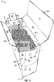
- Fig. 1 is a plan view of an exterior surface 1 of a blank 3 that can be obtained and used to form a carton 5 ( Fig. 3 ) according to one exemplary embodiment of the disclosure.
- the carton 5 can be used to hold at least one article or a plurality of articles such as food products P ( Fig. 3 ), e.g., pasta, cereal, candy, energy bars, granola bars, dairy bars, or any other food product such as beverage products, liquid or dry product (such as laundry detergent or cosmetics), and/or any other article or product.
- the food product P can be a flowable product. As shown in Fig.
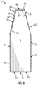
- the carton 5 has a gable top 8, e.g., a top portion that has a tapered and/or gable-type configuration that is configured to seal the carton 5 and contain the food product P in the carton 5.
- the carton 5 can include various dispensing features and various handle features without departing from the disclosure.
- the blank 3 as shown, has a longitudinal axis L1 and a lateral axis L2.
- the blank 3 includes a back panel 25 foldably connected to a first side panel 27 at a lateral fold line 29.
- a front panel 31 is foldably connected to the first side panel 27 at a lateral fold line 33.
- a second side panel 37 is foldably connected t ⁇ the front panel 31 at a lateral fold line 39.
- An adhesive flap 41 is foldably connected to the second side panel 37 at a lateral fold line 45.
- respective bottom end flaps 49, 51, 53, 55 are foldably connected to the respective back panel 25, the first side panel 27, the front panel 31, and the second side panel 37.
- the bottom end flaps 49, 51, 53, 55 are foldably connected to respective panels 25, 27, 31, 37 at a marginal portion of the blank 3 by a longitudinal fold line 62.
- the fold line 62 can be otherwise shaped or be offset at portions of the blank 3 without departing from the disclosure.
- the bottom end flaps 49, 51, 53, 55 have features for facilitating at least partial overlapping of the end flaps 49, 51, 53, 55 to form a closed bottom 11 ( Fig. 3 ) of the carton 5.
- the bottom end flap 49 can include a pair of respective deboss lines 57, 59 that define respective deboss regions 58, 60 on the bottom end flap 49 and the bottom end flap 53 can include a pair of respective emboss lines 61, 63 that define respective emboss regions 62, 64 on the bottom end flap 53.
- the end flaps 49, 51, 53, 55 could be otherwise shaped, arranged, and/or configured, for example, including differentlyshaped or arranged surface features, without departing from the disclosure.
- respective top end flaps 65, 67, 69, 71 are foldably connected to the respective back panel 25, the first side panel 27, the front panel 31, and the second side panel 37 at a marginal portion of the blank 3 at portions of a longitudinal fold line 64.
- the fold line 64 can be otherwise shaped or be offset at portions of the blank 3 without departing from the disclosure.
- the top end flaps 65, 67, 69, and 71 have features for facilitating at least partial overlapping of the end flaps 65, 67, 69, and 71 to form the gable top 8 of the carton 5 ( Fig. 7 ).
- the top end flap 65 includes a proximal portion 73 foldably connected to the back panel 25 at a portion 64a of the longitudinal fold line 64, and a distal portion 75 foldably connected to the proximal portion 73 at a longitudinal fold line 77.
- the end flap 69 is foldably connected to front panel 31 at a portion 64b of the longitudinal fold line 64.
- the end flaps 65, 67, 69, and 71 could be otherwise shaped, arranged, and/or configured without departing from the disclosure,
- the blank 3 includes a first gusset 79 comprising an upper portion 28 of the first side panel 27,
- the first gusset 79 includes a central or first gusset panel 81 foldably connected to a second gusset panel 83 and a third gusset panel 85 at respective fold lines 84, 86.
- the fold line 84 includes a first oblique portion 84a intersecting a second oblique portion 84b
- the fold line 86 includes a first oblique portion 86a intersecting a second oblique portion 86b.
- the first oblique portion 84a can intersect the second oblique portion 84b at an angle, for example, an obtuse angle
- the first oblique portion 86a can intersect the second oblique portion 86b at an angle, for example, an obtuse angle
- the central gusset panel 81 is also foldably connected to a lower portion 30 of the first side panel 27 at a fold line 82 that intersects and interconnects the respective second oblique portions 84b, 86b of the respective fold lines 84, 86.
- the first gusset 79 could have other features and could be otherwise shaped, arranged, and/or configured, without departing from the scope of the disclosure.
- a second gusset 88 comprises an upper portion 32 of the second side panel 37, and has similar features as the first gusset 79, as shown,
- the second gusset 88 includes a central or fourth gusset panel 91 foldably connected to fifth and sixth gusset panels 93, 95 at respective fold lines 94, 96 having respective first and second oblique portions 94a, 94b and 96a, 96b.
- the central gusset panel 91 is foldably connected to a lower portion 34 of the second side panel 37 at a curved fold line 92 that intersects and interconnects the respective second oblique portions 94b, 96b of the respective fold lines 94, 96.
- the central gusset panels 81, 91 are connected to a respective end flap 67, 71 at respective portions 64c, 64d of the longitudinal fold line 64.
- the gussets 79, 88 could be otherwise shaped, arranged, configured, and/or oriented without departing from the disclosure.
- first and second gussets 79, 88 each include respective panels 81, 83, 85 and 91, 93, 95 that are configured for movement relative to one another to facilitate formation of the gable top 8 ( Fig. 7 ), as described herein.
- the carton 5 is formed from the blank 3 by folding the respective panels 25, 27, 31, 37 at respective fold lines 29, 33, 39 to at least partially extend around an interior 6 of the carton 5.
- the adhesive flap 41 can be folded about the fold line 45 and adhered to the back panel 25 to maintain the carton 5 in the illustrated open-ended sleeve configuration.
- the bottom 11 of the carton 5 can be closed by folding the bottom end flaps 49, 51, 53, 55 at respective portions of the fold line 62 toward the interior 6 of the carton 5 and overlapping the bottom end flaps 49, 51, 53, 55, one or more of which can be positioned into face-to-face contact.
- the bottom end flaps 49, 53 can be positioned in overlapping relation, for example, at least partial face-to-face contact, with the bottom end flaps 51, 55 disposed therebetween.
- the bottom end flap 51 can be positioned in overlapping relation between the bottom end flaps 49, 53 and in substantial alignment with each of the deboss region 60 and the emboss region 62 such that the bottom end flap 51 is in at least partial face-to-face contact with each of the bottom end flaps 49, 53.
- the bottom end flap 55 can be positioned in overlapping relation between the bottom end flaps 49, 53 and in substantial alignment with each of the deboss region 58 and the emboss region 64 such that the bottom end flap 55 is in at least partial face-to-face contact with each of the bottom end flaps 49, 53.
- the emboss region 62 and the deboss region 60 can be provided to accommodate the positioning of the bottom end flap 51 therebetween, and the emboss region 64 and the deboss region 58 can be provided to accommodate the positioning of the bottom end flap 55 therebetween.
- One or more of the bottom end flaps 49, 51, 53, 55 can be adhesively secured, for example, with glue, without departing from the disclosure.
- Such an arrangement of the bottom end flaps 49, 51, 53, 55 can provide a substantially sift-minimixing or sift-proof configuration to the bottom 11 of the carton 5, which can inhibit, minimize, and/or prevent the passage of flowable products P ( Fig.
- the bottom 11 of the carton 5 can also be provided in a substantially sealed, e.g., hermetically sealed, arrangement in the configuration described above, or in a different configuration, without departing from the disclosure.
- the above-described formation of the carton 5 into the illustrated open-top configuration can be accomplished, for example, with a packaging system that can comprise different stations, modules, or components, such as a carton forming station, a wrapping station, a pick and place station, a closing or sealing station, or any other suitable station or components.
- the blank 3 can be formed into the carton 5 by other packaging systems without departing from the disclosure.
- the interior 6 of the carton 5 can be loaded with articles, such as flowable products P, as shown, by a suitable packaging or handling system (not shown) or, in other embodiments, can be manually loaded with articles.
- the gable top 8 of the carton 5 can be closed by activating the gussets 79, 88 to position the respective central gusset panels 81, 91 inwardly toward the interior 6 of the carton 5 such that the second and third gusset panels 83, 85 and the fifth and sixth gusset panels 93, 95 are obliquely disposed relative to the respective back and front panels 25, 31.
- the respective central gusset panels 81, 91 may be moved inwardly toward the interior 6 of the carton 5 respective longitudinal distances D1 and D2.
- the end flap 69 may have a longitudinal length, e.g., width, defined by and/or substantially equal to a distance D3 and the front panel 31 can have a longitudinal length defined by and/or substantially equal to a distance D4 such that the sum of D1, D2, and D3 is substantially equal to D4.
- the distances D1 and D2 can be substantially similar, or, in one embodiment, may be different.
- respective top portions 43, 45 of the respective back panel 25 and front panel 31 are drawn to bend or curve toward one another such that the top portions 43, 45 are disposed in an oblique arrangement relative to respective bottom portions 47, 48 of the respective back panel 25 and front panel 31.
- the central gusset panels 81, 91 are positioned in an inwardly spaced arrangement with respect to the respective lower portions 30, 34 of the respective side panels 27, 37.
- Such positioning of the gussets 79, 88 can be accomplished, for example, by drawing or "pinching" the back panel 25 and the front panel 31 toward one another such that the gussets 79, 88 are activated as described above.
- such activation of the gussets 79, 88 can occur directly, for example, by manual engagement of one or more portions of the gussets 79, 88 by a user, or, in another embodiment, through indirect activation by the approximation or pinching of the back panel 25 and the front panel 31 toward one another.
- activation of the gussets 79, 88 results in at least partial folding of the second and third gusset panels 83, 85 relative to the central panel 81 at the respective fold lines 84, 86 and at least partial folding of the fifth and sixth gusset panels 93, 95 relative to the central panel 91 at respective fold lines 94, 96, Further, the second and third gusset panels 83, 85 are at least partially folded relative to the respective front and back panels 25, 31 at portions of respective fold lines 29, 33 and the fifth and sixth gusset panels 93, 95 are at least partially folded relative to the respective front and back panels 31 , 25 at respective fold lines 39, 45.
- the central panels 81, 91 are also at least partially folded relative to the respective lower portions 30, 34 of the respective first and second side panels 27, 37 at respective fold lines 82, 92.
- the gusset panels 83, 95 overlap and are in at least partial face-to-face contact with the back panel 25 and the gusset panels 85, 93 overlap and are in at least partial face-to-face contact with the front panel 31.
- the top end flaps 67, 69, 71 can be folded at respective portions 64b, 64c, 64d of the longitudinal fold line 64 toward the interior 6 of the carton 5 to provide a first closure 7 of the interior 6 of the carton 5.
- One or more portions of the gussets 79, 88 adjacent the respective flaps 67, 71 also cooperate to form the first closure 7.
- the first closure 7 provides a seal at the top of the front panel 31, the first side panel 27, the second side panel 37, and the back panel 25,
- the top end flap 69 can first be folded downwardly at the portion 64b of the longitudinal fold line 64 and the end flaps 67, 71 can then invention-conform be folded downwardly at respective portions 64c, 64d of the longitudinal fold line 64 to at least partially overlap the top end flap 69 in at least partial face-to-face contact, which, in addition to portions of the adjacent gussets 79, 88, provide the first closure 7 that closes the interior 6 of the carton 5.
- the end flaps 67, 71 can be secured to the top end flap 69, for example, with an adhesive such as glue.
- the first closure 7 includes the gusset panels 83, 95 in at least partial face-to-face contact with the back panel 25 and the gusset panels 85, 93 in at least partial face-to-face contact with the front panel 31 to seal or otherwise prevent product P front passing through the top of the gussets 79, 88.
- the proximal portion 73 of the end flap 65 can be folded downwardly at the portion 64a of the longitudinal fold line 64 to overlap and be in in at least partial face-to-face contact with the first closure 7 formed by the end flaps 67, 69, 71 and the gussets, 79, 88, as shown.
- the proximal portion 73 overlaps and is in at least partial face-to-face contact with the end flaps 67, 69, 71 and is substantially parallel to the bottom 11 of the carton 5.
- the distal portion 75 of the end flap 65 can be folded downwardly at fold line 77 to overlap the front panel 31 in at least partial face-to-face contact such that the proximal and distal portions 73, 75 of the end flap 65 at least partially overlap and envelop, e.g., at least partially extend past or overhang, the first closure 7.
- the distal portion 75 of the end flap 65 may be maintained in face-to-face contact with the front panel 31, for example, with an adhesive such as glue.
- one or more interlocking features for example, tabs and slots, can be provided to one or both of the distal portion 75 of the end flap 65 and the front panel 31 to maintain face-to-face contact thereof.
- the carton 5 provides the first closure 7 being at least partially overlapped and enveloped by the end flap 65 such that the end flap 65 provides a second closure 9 of the carton 5.
- the distal portion 75 of the end flap 65 extends past any margins, seams, and/or gaps associated with the first closure 7, for example, between top end flaps 67, 69, 71, such that particulate, for example, fragmentary or smaller pieces of flowable products P are maintained within the interior 6 of the carton 5.
- the second closure 9 also provides a seal at the top of the front panel 31, the first side panel 27, the second side panel 37, and the back panel 25.
- the positioning of the end flap 65 to overlap the closure 7 may provide one or more serpentine, torturous, or otherwise segmented pathways defined between portions of the first closure 7 and portions of the second closure 9 that inhibit the passage and/or exit of particulate from the interior 6 of the carton 5 in addition to the first closure 7.
- Such pathways may be sealed, for example, by the at least partial face-to-face contact of portions of the first closure 7 and the second closure 9, and such sealing can be reinforced, for example, with an adhesive such as glue.
- sealed pathways 98, 99 can be defined between the respective portions 73, 75 of the end flap 65 and the respective end flap 69 and front panel 31.
- the continuous configuration of gussets 79, 88 configuration of the carton 5 that minnimizes the peresence of discontinuities adjacent provides a folded configuration of the carton 5 that minimizes the presence of discontinuities adjacent the interior 6 of the carton 5, for example, margins, seams, and/or gaps between adjacent panels and/or flaps.
- the proximal protion 73 of the end flap 65 extends across the top of the gusset panels 95, 83 that are in at least partial face-to-face contact with the back panel 25 and the top of the gusset panels 85, 93 that are in at least partial face-to-iace contact with the front panel 31.
- the tops of the gussets 79, 88 are sealed to prevent material from passing from the interior 6 through any space between the gusset panels 95, 83 and the back panel 25 and the gusset panels 85, 93 and the front panel 31.
- the carton 5 incorporates the first closure 7 the second closure 9 that at least partially overlaps the first closure 7, and the gussets 79, 88 such that the carton 5 provides a sift-proof or sift-minimizing configuration to inhibit, minimize, and/or prevent the passage of flowable products P (e.g., granular or powdered products) or associated particulate from within the interior 6 of the carton 5.
- flowable products P e.g., granular or powdered products
- Such configuration may be desirable, for example, in the case of smaller food products or other flowable products P, easily frangible food products P, and/or in instances in which carton 5 may be subject to movement or jostling.
- such configuration can provide a substantially sealed, e.g., hermetically sealed, condition of the gable top 8 of the carton 5.
- the tapered configuration of the gable top 8 of the carton 5 (including the flat, planar configuration of the proximal portion 73 of end flap 65) provides a visually-distinctive carton configuration that can be readily identified among other cartons or packages.
- the carton 5 could include various handle features for carrying the carton and could include various dispenser features for opening the carton. Further, the carton 5 could include other pand/flap closing configurations without departing from the disclosure. In one embodiment, the carton 5 can include a liner for maintaining food products P ( Fig. 3 ) therein.
- the blanks according to the present disclosure can be, for example, formed from coated paperboard and similar materials,
- the interior and/or exterior sides of the blanks can be coated with a clay coating.
- the clay coating may then be printed over with product, advertising, price coding, and other information or images.
- the blanks may then be coated with a varnish to protect any information printed on the blank.
- the blanks may also be coated with, for example, a moisture barrier layer, on either or both sides of the blank.
- the blanks may be constructed of paperboard of a caliper such that it is heavier and more rigid than ordinary paper.
- the blanks can also be constructed of other materials, such as cardboard, hard paper, or any other material having properties suitable for enabling the carton to function at least generally as described herein.
- the blanks can also be laminated or coated with one or more sheet-like materials at selected panels or panel sections.
- a fold line can be any substantially linear, although not necessarily straight, form of weakening that facilitates folding there along. More specifically, but not for the purpose of narrowing the scope of the present disclosure, fold lines include: a score line, such as lines formed with a blunt scoring knife, or the like, which creates a crushed portion in the material along the desired line of weakness; a cut that extends partially into a material along the desired line of weakness, and/or a series of cuts that extend partially into and/or completely through the material along the desired line of weakness; and various combinations of these features.
- a score line such as lines formed with a blunt scoring knife, or the like, which creates a crushed portion in the material along the desired line of weakness
- a cut that extends partially into a material along the desired line of weakness, and/or a series of cuts that extend partially into and/or completely through the material along the desired line of weakness; and various combinations of these features.
- a tear line can include: a slit that extends partially into the material along the desired line of weakness, and/or a series of spaced apart slits that extend partially into and/or completely through the material along the desired line of weakness, or various combinations of these features.
- one type tear line is in the form of a series of spaced apart slits that extend completely through the material, with adjacent slits being spaced apart slightly so that a nick (e.g., a small somewhat bridging-like piece of the material) is defined between the adjacent slits for typically temporarily connecting the material across the tear line. The nicks are broken during tearing along the tear line.
- the nicks typically are a relatively small percentage of the tear line, and alternatively the nicks can be omitted from or torn in a tear line such that the tear line is a continuous cut line. That is, it is within the scope of the present disclosure for each of the tear lines to be replaced with a continuous slit, or the like.
- a cut line can be a continuous slit or could be wider than a slit without departing from the present disclosure.
- the above embodiments may be described as having one or more panels adhered together by glue during erection of the carton embodiments.
- glue is intended to encompass all manner of adhesives commonly used to secure carton panels in place.
Description
- This application claims the benefit of
U.S. Provisional Patent Application No. 62/445,990, filed on January 13, 2017 - The present disclosure relates to cartons, blanks for forming cartons, and methods associated with cartons and blanks for holding and carrying at least one article. Particularly, the present disclosure relates to a carton having a gable top with a sift-minimizing top closure configuration. A carton in accordance with the preamble of claim 1 is known from
US 5 326 024 A . - According to one aspect of the disclosure, a carton for holding at least one article, the carton comprises a plurality of panels, a plurality of panels, a first gusset, and a second gusset. The plurality of panels extends at least partially around an interior of the carton, the plurality of panels comprises a front panel, a first side panel, a second side panel, and a back panel. The plurality of end flaps is foldably connected to respective panels of the plurality of panels, the plurality of end flaps comprises a first end flap foldably connected to the front panel and a second end flap foldably connected to the back panel. The first gusset is foldably connected to a portion of the first side panel and the second gusset is foldably connected to a portion of the second side panel. At least the first end flap, the first gusset is foldably connected to a portion of the second side panel. At least the first end flap, the first gusset, and the second gusset cooperate to form a first closure of the carton, and the second end flap forms a second closure of the carton, the second closure at least partially overlaps the first closure, whereby the closures provide first and second seals as further specified in claim 1.
- According to another aspect of the disclosure, a blank for forming a carton for holding at least one article comprises a plurality of panels, a plurality of end flaps, a first gusset, and a second gusset. The plurality of panels is for extending at least partially around an interior of the carton formed from the blank, the plurality of panels comprises a front panel, a first side panel, a second side panel, and a back panel. The plurality of end flaps is foldably connected to respective panels of the plurality of panels, the plurality of end flaps comprises a first end flap foldably connected to the front panel and a second end flap foldably connected to the back panel. The first gusset is foldably connected to a portion of the first side panel and the second gusset is foldably connected to a portion of the second side panel. At least the first end flap, the first gusset, and the second gusset are for cooperating to form a first closure of the carton formed from the blank, and the second end flap is for forming a second closure of the carton formed from the blank, the second closure is for at least partially overlapping the first closure of the carton formed from the blank to provide first and second seals as further specified in claim 6.
- According to another aspect of the disclosure, a method of forming a carton for holding at least one article comprises obtaining a blank. The blank comprises a plurality of panels and a plurality of end flaps, the plurality of panels comprises a from panel, a first side panel, a second side panel, and a back panel, and the plurality of end flaps are foldably connected to respective panels of the plurality of panels. The plurality of end flaps comprises a first end flap foldably connected to the front panel and a second end flap foldably connected to the back panel. The blank further comprises a first gusset foldably connected to a portion of the first side panel and a second gusset foldably connected to a portion of the second side panel. The method further comprises folding the plurality of panels to at least partially extend around an interior of the carton. The method further comprises positioning the first end flap, the first gusset, and the second gusset to form a first closure of the carton. The method further comprises positioning the second end flap to form a second closure of the carton, the second closure at least partially overlaps the first closure, whereby the closures provide first and second seals as further specified in
claim 11. - According to common practice, the various features of the drawings discussed below are not necessarily drawn to scale. Dimensions of various features and elements in the drawings may be expanded or reduced to more clearly illustrate the embodiments of the disclosure.
-
-
Fig. 1 is a plan view of an exterior surface of a blank for forming a carton according to one exemplary embodiment of the disclosure. -
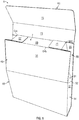
Fig. 2 is a perspective view of a partially-assembled configuration of a carton formed from the blank ofFig. 1 according to one exemplary embodiment of the disclosure, -
Fig. 3 is a perspective view of a carton formed from the blank ofFig. 1 according to one exemplary embodiment of the disclosure and in a partially-open configuration. -
Fig. 4 is a first sequential view of the carton ofFig. 3 during a closing operation according to one exemplary embodiment of the disclosure. -
Fig. 5 is a second sequential view of the carton ofFig. 3 during a closing operation according to one exemplary embodiment of the disclosure. -
Fig. 6 is a third sequential view of the carton ofFig. 3 during a closing operation according to one exemplary embodiment of the disclosure. -
Fig. 7 is a fourth sequential view of the carton ofFig. 2 during a closing operation according to one exemplary embodiment of the disclosure. -
Fig. 8 is a cross-sectional view taken along line 8-8 ofFig. 7 . - Corresponding parts are designated by corresponding reference numbers throughout the drawings.
- Cartons according to the present disclosure can accommodate articles of numerous different shapes. For the purpose of illustration and not for the purpose of limiting the scope of the disclosure and that of the invention as defined by the claims, the following detailed description describes articles such as food products at least partially disposed within the carton embodiments.
- In this specification, the terms "lower," "bottom," "upper", "top", "front", and "back" indicate orientations determined in relation to fully erected cartons. Further, as described herein, cartons may be formed from blanks by overlapping multiple panels and/or end flaps. Such panels and/or end flaps may be designated herein in terms relative to one another, e.g., "first", "second", "third", etc., in sequential or non-sequential reference, without departing from the disclosure.
-
Fig. 1 is a plan view of an exterior surface 1 of a blank 3 that can be obtained and used to form a carton 5 (Fig. 3 ) according to one exemplary embodiment of the disclosure. Thecarton 5 can be used to hold at least one article or a plurality of articles such as food products P (Fig. 3 ), e.g., pasta, cereal, candy, energy bars, granola bars, dairy bars, or any other food product such as beverage products, liquid or dry product (such as laundry detergent or cosmetics), and/or any other article or product. In one embodiment, the food product P can be a flowable product. As shown inFig. 7 , thecarton 5 has a gable top 8, e.g., a top portion that has a tapered and/or gable-type configuration that is configured to seal thecarton 5 and contain the food product P in thecarton 5. Thecarton 5 can include various dispensing features and various handle features without departing from the disclosure. - The blank 3, as shown, has a longitudinal axis L1 and a lateral axis L2. The blank 3 includes a
back panel 25 foldably connected to afirst side panel 27 at alateral fold line 29. Afront panel 31 is foldably connected to thefirst side panel 27 at alateral fold line 33. Asecond side panel 37 is foldably connected tο thefront panel 31 at alateral fold line 39. Anadhesive flap 41 is foldably connected to thesecond side panel 37 at alateral fold line 45. - As shown in
Fig. 1 , respectivebottom end flaps respective back panel 25, thefirst side panel 27, thefront panel 31, and thesecond side panel 37. Thebottom end flaps respective panels longitudinal fold line 62. Thefold line 62 can be otherwise shaped or be offset at portions of the blank 3 without departing from the disclosure. Further, thebottom end flaps end flaps Fig. 3 ) of thecarton 5. As shown, thebottom end flap 49 can include a pair ofrespective deboss lines respective deboss regions bottom end flap 49 and thebottom end flap 53 can include a pair ofrespective emboss lines respective emboss regions bottom end flap 53. Theend flaps - As also shown in
Fig. 1 , respectivetop end flaps respective back panel 25, thefirst side panel 27, thefront panel 31, and thesecond side panel 37 at a marginal portion of the blank 3 at portions of alongitudinal fold line 64. Thefold line 64 can be otherwise shaped or be offset at portions of the blank 3 without departing from the disclosure. Further, thetop end flaps end flaps Fig. 7 ). As shown, thetop end flap 65 includes aproximal portion 73 foldably connected to theback panel 25 at aportion 64a of thelongitudinal fold line 64, and adistal portion 75 foldably connected to theproximal portion 73 at alongitudinal fold line 77. Theend flap 69 is foldably connected tofront panel 31 at aportion 64b of thelongitudinal fold line 64. Theend flaps - In the illustrated embodiment, the blank 3 includes a
first gusset 79 comprising anupper portion 28 of thefirst side panel 27, Thefirst gusset 79 includes a central orfirst gusset panel 81 foldably connected to asecond gusset panel 83 and athird gusset panel 85 atrespective fold lines fold line 84 includes afirst oblique portion 84a intersecting asecond oblique portion 84b, and thefold line 86 includes afirst oblique portion 86a intersecting asecond oblique portion 86b. Thefirst oblique portion 84a can intersect thesecond oblique portion 84b at an angle, for example, an obtuse angle, and thefirst oblique portion 86a can intersect thesecond oblique portion 86b at an angle, for example, an obtuse angle. Thecentral gusset panel 81 is also foldably connected to alower portion 30 of thefirst side panel 27 at afold line 82 that intersects and interconnects the respective secondoblique portions respective fold lines first gusset 79 could have other features and could be otherwise shaped, arranged, and/or configured, without departing from the scope of the disclosure. - As shown, a
second gusset 88 comprises anupper portion 32 of thesecond side panel 37, and has similar features as thefirst gusset 79, as shown, In particular, thesecond gusset 88 includes a central orfourth gusset panel 91 foldably connected to fifth andsixth gusset panels respective fold lines oblique portions central gusset panel 91 is foldably connected to alower portion 34 of thesecond side panel 37 at acurved fold line 92 that intersects and interconnects the respective secondoblique portions respective fold lines central gusset panels respective end flap respective portions longitudinal fold line 64. Thegussets - In this regard, the first and
second gussets respective panels Fig. 7 ), as described herein. - Referring additionally to
Fig. 2 , in accordance with one exemplary embodiment, thecarton 5 is formed from the blank 3 by folding therespective panels respective fold lines carton 5. Theadhesive flap 41 can be folded about thefold line 45 and adhered to theback panel 25 to maintain thecarton 5 in the illustrated open-ended sleeve configuration. - Referring additionally to
Fig. 3 , the bottom 11 of thecarton 5 can be closed by folding the bottom end flaps 49, 51, 53, 55 at respective portions of thefold line 62 toward the interior 6 of thecarton 5 and overlapping the bottom end flaps 49, 51, 53, 55, one or more of which can be positioned into face-to-face contact. In the exemplary embodiment shown, the bottom end flaps 49, 53 can be positioned in overlapping relation, for example, at least partial face-to-face contact, with the bottom end flaps 51, 55 disposed therebetween. In particular, thebottom end flap 51 can be positioned in overlapping relation between the bottom end flaps 49, 53 and in substantial alignment with each of thedeboss region 60 and theemboss region 62 such that thebottom end flap 51 is in at least partial face-to-face contact with each of the bottom end flaps 49, 53. Further, thebottom end flap 55 can be positioned in overlapping relation between the bottom end flaps 49, 53 and in substantial alignment with each of thedeboss region 58 and theemboss region 64 such that thebottom end flap 55 is in at least partial face-to-face contact with each of the bottom end flaps 49, 53. In this regard, theemboss region 62 and thedeboss region 60 can be provided to accommodate the positioning of thebottom end flap 51 therebetween, and theemboss region 64 and thedeboss region 58 can be provided to accommodate the positioning of thebottom end flap 55 therebetween. One or more of the bottom end flaps 49, 51, 53, 55 can be adhesively secured, for example, with glue, without departing from the disclosure. Such an arrangement of the bottom end flaps 49, 51, 53, 55 can provide a substantially sift-minimixing or sift-proof configuration to the bottom 11 of thecarton 5, which can inhibit, minimize, and/or prevent the passage of flowable products P (Fig. 3 ) stored in the interior 6 of thecarton 5 or associated particulate, as described further herein. The bottom 11 of thecarton 5 can also be provided in a substantially sealed, e.g., hermetically sealed, arrangement in the configuration described above, or in a different configuration, without departing from the disclosure. - The above-described formation of the
carton 5 into the illustrated open-top configuration can be accomplished, for example, with a packaging system that can comprise different stations, modules, or components, such as a carton forming station, a wrapping station, a pick and place station, a closing or sealing station, or any other suitable station or components. The blank 3 can be formed into thecarton 5 by other packaging systems without departing from the disclosure. As shown, the interior 6 of thecarton 5 can be loaded with articles, such as flowable products P, as shown, by a suitable packaging or handling system (not shown) or, in other embodiments, can be manually loaded with articles. - Still referring to
Fig. 1 , and referring additionally toFigs. 4-7 , the gable top 8 of thecarton 5 can be closed by activating thegussets central gusset panels carton 5 such that the second andthird gusset panels sixth gusset panels front panels central gusset panels carton 5 respective longitudinal distances D1 and D2. As shown, theend flap 69 may have a longitudinal length, e.g., width, defined by and/or substantially equal to a distance D3 and thefront panel 31 can have a longitudinal length defined by and/or substantially equal to a distance D4 such that the sum of D1, D2, and D3 is substantially equal to D4. The distances D1 and D2 can be substantially similar, or, in one embodiment, may be different. - As shown, upon activation of the
gussets top portions respective back panel 25 andfront panel 31 are drawn to bend or curve toward one another such that thetop portions respective bottom portions respective back panel 25 andfront panel 31. - In this regard, the
central gusset panels lower portions respective side panels gussets back panel 25 and thefront panel 31 toward one another such that thegussets gussets gussets back panel 25 and thefront panel 31 toward one another. In the exemplary embodiment shown, activation of thegussets third gusset panels central panel 81 at therespective fold lines sixth gusset panels central panel 91 atrespective fold lines third gusset panels back panels respective fold lines sixth gusset panels back panels respective fold lines central panels lower portions second side panels respective fold lines gusset panels back panel 25 and thegusset panels front panel 31. - As shown in
Figs. 4 and5 , the top end flaps 67, 69, 71 can be folded atrespective portions longitudinal fold line 64 toward the interior 6 of thecarton 5 to provide afirst closure 7 of the interior 6 of thecarton 5. One or more portions of thegussets respective flaps first closure 7. Thefirst closure 7 provides a seal at the top of thefront panel 31, thefirst side panel 27, thesecond side panel 37, and theback panel 25, In the illustrated embodiment, thetop end flap 69 can first be folded downwardly at theportion 64b of thelongitudinal fold line 64 and the end flaps 67, 71 can then invention-conform be folded downwardly atrespective portions longitudinal fold line 64 to at least partially overlap thetop end flap 69 in at least partial face-to-face contact, which, in addition to portions of theadjacent gussets first closure 7 that closes the interior 6 of thecarton 5. The end flaps 67, 71 can be secured to thetop end flap 69, for example, with an adhesive such as glue. In one embodiment, thefirst closure 7 includes thegusset panels back panel 25 and thegusset panels front panel 31 to seal or otherwise prevent product P front passing through the top of thegussets - Referring to
Fig. 6 , theproximal portion 73 of theend flap 65 can be folded downwardly at theportion 64a of thelongitudinal fold line 64 to overlap and be in in at least partial face-to-face contact with thefirst closure 7 formed by the end flaps 67, 69, 71 and the gussets, 79, 88, as shown. In such an arrangement, theproximal portion 73 overlaps and is in at least partial face-to-face contact with the end flaps 67, 69, 71 and is substantially parallel to the bottom 11 of thecarton 5. As shown inFig. 7 , thedistal portion 75 of theend flap 65 can be folded downwardly atfold line 77 to overlap thefront panel 31 in at least partial face-to-face contact such that the proximal anddistal portions end flap 65 at least partially overlap and envelop, e.g., at least partially extend past or overhang, thefirst closure 7. Thedistal portion 75 of theend flap 65 may be maintained in face-to-face contact with thefront panel 31, for example, with an adhesive such as glue. In other embodiments, one or more interlocking features, for example, tabs and slots, can be provided to one or both of thedistal portion 75 of theend flap 65 and thefront panel 31 to maintain face-to-face contact thereof. - Turning additionally to
Fig. 8 , in a closed condition, thecarton 5 provides thefirst closure 7 being at least partially overlapped and enveloped by theend flap 65 such that theend flap 65 provides asecond closure 9 of thecarton 5. In particular, thedistal portion 75 of theend flap 65 extends past any margins, seams, and/or gaps associated with thefirst closure 7, for example, between top end flaps 67, 69, 71, such that particulate, for example, fragmentary or smaller pieces of flowable products P are maintained within the interior 6 of thecarton 5. In this regard, thesecond closure 9 also provides a seal at the top of thefront panel 31, thefirst side panel 27, thesecond side panel 37, and theback panel 25. Referring additionally to the cross-sectional view ofFig. 8 , the positioning of theend flap 65 to overlap theclosure 7 may provide one or more serpentine, torturous, or otherwise segmented pathways defined between portions of thefirst closure 7 and portions of thesecond closure 9 that inhibit the passage and/or exit of particulate from the interior 6 of thecarton 5 in addition to thefirst closure 7. Such pathways may be sealed, for example, by the at least partial face-to-face contact of portions of thefirst closure 7 and thesecond closure 9, and such sealing can be reinforced, for example, with an adhesive such as glue. In the exemplary embodiment shown, sealedpathways respective portions end flap 65 and therespective end flap 69 andfront panel 31. Further, the continuous configuration ofgussets carton 5 that minnimizes the peresence of discontinuities adjacent provides a folded configuration of thecarton 5 that minimizes the presence of discontinuities adjacent the interior 6 of thecarton 5, for example, margins, seams, and/or gaps between adjacent panels and/or flaps. Theproximal protion 73 of theend flap 65 extends across the top of thegusset panels back panel 25 and the top of thegusset panels front panel 31. When thedistal portion 75 of theend flap 65 is downwardly folded the tops of thegussets gusset panels back panel 25 and thegusset panels front panel 31. - Accordingly, and as described herein, the
carton 5 incorporates thefirst closure 7 thesecond closure 9 that at least partially overlaps thefirst closure 7, and thegussets carton 5 provides a sift-proof or sift-minimizing configuration to inhibit, minimize, and/or prevent the passage of flowable products P (e.g., granular or powdered products) or associated particulate from within the interior 6 of thecarton 5. Such configuration may be desirable, for example, in the case of smaller food products or other flowable products P, easily frangible food products P, and/or in instances in whichcarton 5 may be subject to movement or jostling. In one embodiment, such configuration can provide a substantially sealed, e.g., hermetically sealed, condition of the gable top 8 of thecarton 5. Further still, the tapered configuration of the gable top 8 of the carton 5 (including the flat, planar configuration of theproximal portion 73 of end flap 65) provides a visually-distinctive carton configuration that can be readily identified among other cartons or packages. - The
carton 5 could include various handle features for carrying the carton and could include various dispenser features for opening the carton. Further, thecarton 5 could include other pand/flap closing configurations without departing from the disclosure. In one embodiment, thecarton 5 can include a liner for maintaining food products P (Fig. 3 ) therein. - The blanks according to the present disclosure can be, for example, formed from coated paperboard and similar materials, For example, the interior and/or exterior sides of the blanks can be coated with a clay coating. The clay coating may then be printed over with product, advertising, price coding, and other information or images. The blanks may then be coated with a varnish to protect any information printed on the blank. The blanks may also be coated with, for example, a moisture barrier layer, on either or both sides of the blank. In accordance with the above-described embodiments, the blanks may be constructed of paperboard of a caliper such that it is heavier and more rigid than ordinary paper. The blanks can also be constructed of other materials, such as cardboard, hard paper, or any other material having properties suitable for enabling the carton to function at least generally as described herein. The blanks can also be laminated or coated with one or more sheet-like materials at selected panels or panel sections.
- In accordance with the above-described embodiments of the present disclosure, a fold line can be any substantially linear, although not necessarily straight, form of weakening that facilitates folding there along. More specifically, but not for the purpose of narrowing the scope of the present disclosure, fold lines include: a score line, such as lines formed with a blunt scoring knife, or the like, which creates a crushed portion in the material along the desired line of weakness; a cut that extends partially into a material along the desired line of weakness, and/or a series of cuts that extend partially into and/or completely through the material along the desired line of weakness; and various combinations of these features.
- As an example, a tear line can include: a slit that extends partially into the material along the desired line of weakness, and/or a series of spaced apart slits that extend partially into and/or completely through the material along the desired line of weakness, or various combinations of these features. As a more specific example, one type tear line is in the form of a series of spaced apart slits that extend completely through the material, with adjacent slits being spaced apart slightly so that a nick (e.g., a small somewhat bridging-like piece of the material) is defined between the adjacent slits for typically temporarily connecting the material across the tear line. The nicks are broken during tearing along the tear line. The nicks typically are a relatively small percentage of the tear line, and alternatively the nicks can be omitted from or torn in a tear line such that the tear line is a continuous cut line. That is, it is within the scope of the present disclosure for each of the tear lines to be replaced with a continuous slit, or the like. For example, a cut line can be a continuous slit or could be wider than a slit without departing from the present disclosure.
- The above embodiments may be described as having one or more panels adhered together by glue during erection of the carton embodiments. The term "glue" is intended to encompass all manner of adhesives commonly used to secure carton panels in place.
- The foregoing description of the disclosure illustrates and describes various exemplary embodiments. Various additions, modifications, changes, etc., could be made to the exemplary embodiments without departing from the scope of the disclosure and that of the invention as defined by the claims. It is intended that all matter contained in the above description or shown in the accompanying drawings shall be interpreted as illustrative and not in a limiting sense.
Claims (15)
- A carton (5) for holding at least one article (P), the carton (5) comprising:a plurality of panels that extends at least partially around an interior (6) of the carton (5), the plurality of panels comprises a front panel (31), a first side panel (27), a second side panel (37), and a back panel (25);a plurality of end flaps foldably connected to respective panels of the plurality of panels, the plurality of end flaps comprises a first end flap (69) foldably connected to the front panel (31), a second end flap (65) foldably connected to the back panel (25), a third end flap (67) foldably connected to the first side panel (27), and a fourth end flap (71) foldably connected to the second side panel (37); anda first gusset (79) foldably connected to a portion of the first side panel (27) and a second gusset (88) foldably connected to a portion of the second side panel (37),at least the first end flap (69), the first gusset (79), the second gusset (88), the third end flap (67), and the fourth end flap (71) cooperate to form a first closure (7) of the carton (5), and the second end flap (65) forms a second closure (9) of the carton (5), the second closure (9) at least partially overlaps the first closure (7), whereby the carton (5) is characterized in that the third end flap (67) and the fourth end flap (71) overlap the first end flap (69) such that the first closure (7) provides a first seal at the top of the front panel (31), the first side panel (27), the second side panel (37), and the back panel (25), and the second closure (9) at least partially envelops the first closure (7) and provides a second seal at the top of the front panel (31), the first side panel (27), the second side panel (37), and the back panel (25).
- The carton (5) of claim 1, wherein the second end flap (65) comprises a proximal portion (73) foldably connected to a distal portion (75), the proximal portion (73) of the second end flap (65) at least partially overlaps the first end flap (69), and the distal portion (75) of the second end flap (65) at least partially overlaps the front panel (31).
- The carton (5) of claim 1, wherein the second end flap (65) comprises a proximal portion (73) foldably connected to a distal portion (75), a portion of the first gusset (79) is disposed inwardly toward the interior (6) of the carton (5) a first longitudinal distance (D1), a portion of the second gusset (88) is disposed inwardly toward the interior (6) of the carton (5) a second longitudinal distance (D2), the first end flap (69) has a length equal to a third longitudinal distance (D3), and the front panel (31) has a length equal to a fourth longitudinal distance (D4), and the sum of the first longitudinal distance (D1), the second longitudinal distance (D2), and the third longitudinal distance (D3) is substantially equal to the fourth longitudinal distance (D4).
- The carton (5) of claim 1, wherein an upper portion (45) of the front panel (31) is obliquely disposed relative to a lower portion (48) of the front panel (31) and an upper portion (43) of the back panel (25) is obliquely disposed relative to a lower portion (47) of the back panel (25),
the second end flap (65) comprises a proximal portion (73) foldably connected to a distal portion (75), the distal portion (75) of the second end flap (65) is at least partially in face-to-face contact with the upper portion (45) of the front panel (31). - The carton (5) of claim 1, wherein the first gusset (79) comprises a first gusset panel (81), a second gusset panel (83), and a third gusset panel (85),the first gusset panel (81) is foldably connected to each of the second gusset panel (83) and the third gusset panel (85),the first gusset panel (81) is foldably connected to the second gusset panel (83) by a first fold line (84) having a first oblique portion (84a) intersecting a second oblique portion (84b), and the first gusset panel (81) is foldably connected to the third gusset panel (85) by a second fold line (86) having a first oblique portion (86a) and a second oblique portion (86b),the second oblique portion (84b) of the first fold line (84) and the second oblique portion (86b) of the second fold line (86) are interconnected by a curved fold line (82),the second gusset (88) comprises a fourth gusset panel (91), a fifth gusset panel (93), and a sixth gusset panel (95), the fourth gusset panel (91) is foldably connected to the fifth gusset panel (93) at a third fold line (94) and the fourth gusset panel (91) is foldably connected to the sixth gusset panel (95) at a fourth fold line (96), each of the third fold line (94) and the fourth fold line (96) comprises a first oblique portion (94a, 96a) intersecting a second oblique portion (94b, 96b), the second oblique portion (94b) of the third fold line (94) and the second oblique portion (96b) of the fourth fold line (96) are interconnected by a curved fold line (92).
- A blank (3) for forming a carton (5) for holding at least one article (P), the blank (3) comprising:a plurality of panels for extending at least partially around an interior (6) of the carton (5) formed from the blank (3), the plurality of panels comprises a front panel (31), a first side panel (27), a second side panel (37), and a back panel (25);a plurality of end flaps foldably connected to respective panels of the plurality of panels, the plurality of end flaps comprises a first end flap (69) foldably connected to the front panel (31), a second end flap (65) foldably connected to the back panel (25), a third end flap (67) foldably connected to the first side panel (27), and a fourth end flap (71) foldably connected to the second side panel (37); anda first gusset (79) foldably connected to a portion of the first side panel (27) and a second gusset (88) foldably connected to a portion of the second side panel (37),at least the first end flap (69), the first gusset (79), the second gusset (88), the third end flap (67), and the fourth end flap (71) are for cooperating to form a first closure (7) of the carton (5) formed from the blank (3) in which the third end flap (67) and the fourth end flap (71) overlap the first end flap (69) such that the first closure (7) provides a first seal at the top of the front panel (31), the first side panel (27), the second side panel (37), and the back panel (25), and the second end flap (65) is for forming a second closure (9) of the carton (5) formed from the blank (3), the second closure (9) is for at least partially overlapping and enveloping the first closure (7) to provide a second seal at the top of the front panel (31), the first side panel (27), the second side panel (37), and the back panel (25) when the carton (5) is formed from the blank (3).
- The blank (3) of claim 6, wherein the second end flap (65) comprises a proximal portion (73) foldably connected to a distal portion (75), the proximal portion (73) of the second end flap (65) at least partially overlaps the first end flap (69) when the carton (5) is formed from the blank (3), and the distal portion (75) of the second end flap (65) at least partially overlaps the front panel (31) when the carton (5) is formed from the blank (3).
- The blank (3) of claim 6, wherein the second end flap (65) comprises a proximal portion (73) foldably connected to a distal portion (75), a portion of the first gusset (79) is disposed inwardly toward the interior (6) of the carton (5) formed from the blank (3) a first longitudinal distance (D1), a portion of the second gusset (88) is disposed inwardly toward the interior (6) of the carton (5) formed from the blank (3) a second longitudinal distance (D2), the first end flap (69) has a length equal to a third longitudinal distance (D3), and the front panel (31) has a length equal to a fourth longitudinal distance (D4), and the sum of the first longitudinal distance (D1), the second longitudinal distance (D2), and the third longitudinal distance (D3) is substantially equal to the fourth longitudinal distance (D4).
- The blank (3) of claim 6, wherein an upper portion (45) of the front panel (31) is obliquely disposed relative to a lower portion (48) of the front panel (31) and an upper portion (43) of the back panel (25) is obliquely disposed relative to a lower portion (47) of the back panel (25) when the carton (5) is formed from the blank (3),
the second end flap (65) comprises a proximal portion (73) foldably connected to a distal portion (75), the distal portion (75) of the second end flap (65) is at least partially in face-to-face contact with the upper portion (45) of the front panel (31) when the carton (5) is formed from the blank (3). - The blank (3) of claim 6, wherein the first gusset (79) comprises a first gusset panel (81), a second gusset panel (83), and a third gusset panel (85),the first gusset panel (81) is foldably connected to each of the second gusset panel (83) and the third gusset panel (85),the first gusset panel (81) is foldably connected to the second gusset panel (83) by a first fold line (84) having a first oblique portion (84a) intersecting a second oblique portion (84b), and the first gusset panel (81) is foldably connected to the third gusset panel (85) by a second fold line (86) having a first oblique portion (86a) and a second oblique portion (86b),the second oblique portion (84b) of the first fold line (84) and the second oblique portion (86b) of the second fold line (86) are interconnected by a curved fold line (82),the second gusset (88) comprises a fourth gusset panel (91), a fifth gusset panel (93), and a sixth gusset panel (95), the fourth gusset panel (91) is foldably connected to the fifth gusset panel (93) at a third fold line (94) and the fourth gusset panel (91) is foldably connected to the sixth gusset panel (95) at a fourth fold line (96), each of the third fold line (94) and the fourth fold line (96) comprises a first oblique portion (94a, 96a) intersecting a second oblique portion (94b, 96b), the second oblique portion (94b) of the third fold line (94) and the second oblique portion (96b) of the fourth fold line (96) are interconnected by a curved fold line (92).
- A method of forming a carton (5) for holding at least one article (P) in accordance with claim 1, the method comprising:obtaining a blank (3) in accordance with claim 6 comprising a plurality of panels and a plurality of end flaps, the plurality of panels comprises a front panel (31), a first side panel (27), a second side panel (37), and a back panel (25), the plurality of end flaps are foldably connected to respective panels of the plurality of panels, the plurality of end flaps comprises a first end flap (69) foldably connected to the front panel (31), a second end flap (65) foldably connected to the back panel (25), a third end flap (67) foldably connected to the first side panel (27), and a fourth end flap (71) foldably connected to the second side panel (37), the blank (3) comprises a first gusset (79) foldably connected to a portion of the first side panel (27) and a second gusset (88) foldably connected to a portion of the second side panel (37); andfolding the plurality of panels to at least partially extend around an interior (6) of the carton (5);positioning the first end flap (69), the first gusset (79), the second gusset (88), the third end flap (67), and the fourth end flap (71) to form a first closure (7) of the carton (5) in which the third end flap (67) and the fourth end flap (71) overlap the first end flap (69) such that the first closure (7) provides a first seal at the top of the front panel (31), the first side panel (27), the second side panel (37), and the back panel (25); andpositioning the second end flap (65) to form a second closure (9) of the carton (5), the second closure (9) at least partially overlaps and envelops the first closure (7) and provides a second seal at the top of the front panel (31), the first side panel (27), the second side panel (37), and the back panel (25).
- The method of claim 11, wherein the second end flap (65) comprises a proximal portion (73) foldably connected to a distal portion (75), the proximal portion (73) of the second end flap (65) at least partially overlaps the first end flap (69), and the distal portion (75) of the second end flap (65) at least partially overlaps the front panel (31).
- The method of claim 11, wherein the second end flap (65) comprises a proximal portion (73) foldably connected to a distal portion (75), a portion of the first gusset (79) is disposed inwardly toward the interior (6) of the carton (5) a first longitudinal distance (D1), a portion of the second gusset (88) is disposed inwardly toward the interior (6) of the carton (5) a second longitudinal distance (D2), the first end flap (69) has a length equal to a third longitudinal distance (D3), and the front panel (31) has a length equal to a fourth longitudinal distance (D4), and the sum of the first longitudinal distance (D1), the second longitudinal distance (D2), and the third longitudinal distance (D3) is substantially equal to the fourth longitudinal distance (D4).
- The method of claim 11, wherein an upper portion (45) of the front panel (31) is obliquely disposed relative to a lower portion (48) of the front panel (31) and an upper portion (43) of the back panel (25) is obliquely disposed relative to a lower portion (47) of the back panel (25),
the second end flap (65) comprises a proximal portion (73) foldably connected to a distal portion (75), the distal portion (75) of the second end flap (65) is at least partially in face-to-face contact with the upper portion (45) of the front panel (31). - The method of claim 11, wherein the first gusset (79) comprises a first gusset panel (81), a second gusset panel (83), and a third gusset panel (85),the first gusset panel (81) is foldably connected to each of the second gusset panel (83) and the third gusset panel (85),first gusset panel (81) is foldably connected to the second gusset panel (83) by a first fold line (84) having a first oblique portion (84a) intersecting a second oblique portion (84b), and the first gusset panel (81) is foldably connected to the third gusset panel (85) by a second fold line (86) having a first oblique portion (86a) and a second oblique portion (86b),the second oblique portion (84b) of the first fold line (84) and the second oblique portion (86b) of the second fold line (86) are interconnected by a curved fold line (82),the second gusset (88) comprises a fourth gusset panel (91), a fifth gusset panel (93), and a sixth gusset panel (95), the fourth gusset panel (91) is foldably connected to the fifth gusset panel (93) at a third fold line (94) and the fourth gusset panel (91) is foldably connected to the sixth gusset panel (95) at a fourth fold line (96), each of the third fold line (94) and the fourth fold line (96) comprises a first oblique portion (94a, 96a) intersecting a second oblique portion (94b, 96b), the second oblique portion (94b) of the third fold line (94) and the second oblique portion (96b) of the fourth fold line (96) are interconnected by a curved fold line (92).
Applications Claiming Priority (2)
| Application Number | Priority Date | Filing Date | Title |
|---|---|---|---|
| US201762445990P | 2017-01-13 | 2017-01-13 | |
| PCT/US2018/012917 WO2018132359A1 (en) | 2017-01-13 | 2018-01-09 | Carton with top closure |
Publications (3)
| Publication Number | Publication Date |
|---|---|
| EP3568356A1 EP3568356A1 (en) | 2019-11-20 |
| EP3568356A4 EP3568356A4 (en) | 2020-08-05 |
| EP3568356B1 true EP3568356B1 (en) | 2021-11-03 |
Family
ID=62839002
Family Applications (1)
| Application Number | Title | Priority Date | Filing Date |
|---|---|---|---|
| EP18739407.7A Active EP3568356B1 (en) | 2017-01-13 | 2018-01-09 | Carton with top closure |
Country Status (6)
| Country | Link |
|---|---|
| US (1) | US10239651B2 (en) |
| EP (1) | EP3568356B1 (en) |
| CA (1) | CA3045136C (en) |
| ES (1) | ES2903277T3 (en) |
| MX (1) | MX2019008353A (en) |
| WO (1) | WO2018132359A1 (en) |
Families Citing this family (8)
| Publication number | Priority date | Publication date | Assignee | Title |
|---|---|---|---|---|
| CA3089724C (en) | 2018-02-21 | 2023-06-27 | Graphic Packaging International, Llc | Stackable cartons, system, and methods of using the same |
| USD864751S1 (en) | 2018-03-26 | 2019-10-29 | Graphic Packaging International, Llc | Carton arrangement |
| MX2022000857A (en) * | 2019-08-23 | 2022-02-10 | Nestle Sa | Packaging containers, systems, and methods. |
| MX2022005772A (en) | 2019-11-20 | 2022-06-09 | Graphic Packaging Int Llc | Stackable cartons, system, and methods of using the same. |
| USD954549S1 (en) | 2019-12-11 | 2022-06-14 | Graphic Packaging International, Llc | Carton |
| USD954548S1 (en) | 2019-12-11 | 2022-06-14 | Graphic Packaging International, Llc | Carton |
| WO2021262687A1 (en) | 2020-06-24 | 2021-12-30 | Graphic Packaging International, Llc | Shipping and dispensing construct |
| USD996207S1 (en) | 2020-10-29 | 2023-08-22 | Graphic Packaging International, Llc | Dispensing carton |
Family Cites Families (220)
| Publication number | Priority date | Publication date | Assignee | Title |
|---|---|---|---|---|
| US362583A (en) | 1887-05-10 | Paper box | ||
| US83812A (en) | 1868-11-03 | Improved box | ||
| US567649A (en) | 1896-09-15 | Paper receptacle | ||
| US3127082A (en) | 1964-03-31 | And like cartoxing m materials | ||
| US1082868A (en) | 1909-08-02 | 1913-12-30 | Sefton Mfg Company | Paper receptacle. |
| GB104445A (en) | 1916-06-28 | 1917-03-08 | Maude Earle | A Receptacle for Containing and Preserving of Food or the like in Liquid, Plastic, or Solid Forms. |
| US1772625A (en) | 1928-08-31 | 1930-08-12 | Karle Lithographic Company | Reducing carton |
| US1837750A (en) | 1929-11-16 | 1931-12-22 | Bert M Kent | Carton |
| US1842237A (en) | 1930-02-03 | 1932-01-19 | Bert M Kent | Carton |
| GB371064A (en) | 1931-01-27 | 1932-04-21 | Carl Wilhelm Hartmann | Improvements in cartons or packets |
| US1973960A (en) | 1931-04-11 | 1934-09-18 | Fibreboard Products Inc | Container |
| GB385033A (en) | 1931-09-14 | 1932-12-22 | Carl Wilhelm Hartmann | Improvements in and relating to cartons or packages more particularly for granular substances |
| US1998717A (en) | 1933-06-26 | 1935-04-23 | Waldorf Paper Prod Co | Reclosing box |
| US2010863A (en) | 1934-04-21 | 1935-08-13 | Johnson Paul | Folding box with integral spout |
| US2192722A (en) | 1936-03-25 | 1940-03-05 | Owens Illinois Glass Co | Collapsible container |
| US2114623A (en) | 1937-03-04 | 1938-04-19 | Edna May Bergstein | Method of providing for internal atmospheric expansion of filled bags and hermetically sealing same |
| US2361984A (en) | 1941-10-28 | 1944-11-07 | Nat Folding Box Co | Telescopic box |
| US2355665A (en) | 1942-08-05 | 1944-08-15 | Nat Folding Box Co | Hinged cover container |
| US2509289A (en) | 1946-09-26 | 1950-05-30 | Waldorf Paper Prod Co | Carton pouring spout |
| US2475677A (en) | 1946-12-07 | 1949-07-12 | Gardner Board & Carton Co | Folding carton having reclosable pouring spout |
| US2634897A (en) | 1947-10-18 | 1953-04-14 | Bord Max | Pouring spout for cartons |
| US2701678A (en) | 1949-11-12 | 1955-02-08 | Floseal Corp | Pouring spout for cartons |
| US2683953A (en) | 1951-11-20 | 1954-07-20 | Hopkins Agricultural Chemical | Container for rodenticides |
| US2757851A (en) | 1952-03-21 | 1956-08-07 | Moore George Arlington | Containers |
| US2778557A (en) | 1952-05-28 | 1957-01-22 | Moore George Arlington | Unitary container |
| US2738916A (en) | 1953-08-17 | 1956-03-20 | Thomas B R Peters | Closures and seals for cartons |
| US2750096A (en) | 1954-05-20 | 1956-06-12 | Ethel A Misch | Paper containers |
| US2820585A (en) | 1954-07-01 | 1958-01-21 | Interstate Folding Box Co | Pouring opening for containers |
| US2982461A (en) | 1955-03-10 | 1961-05-02 | Pneumatic Scale Corp | Package |
| US2950036A (en) | 1957-07-16 | 1960-08-23 | Pneumatic Scale Corp | Lined carton and method of making the same |
| US2989224A (en) | 1957-08-28 | 1961-06-20 | R A Macplum Ind Inc | Box with pouring spout |
| NL257987A (en) * | 1959-11-16 | |||
| US3085733A (en) | 1960-12-12 | 1963-04-16 | R A Macplum Ind Inc | Carton having built-in pour spout |
| US3133688A (en) | 1962-09-12 | 1964-05-19 | American Can Co | Reclosable angle spout carton |
| CH412695A (en) | 1963-05-12 | 1966-04-30 | Landerer Fa A | Dispenser on flat, stackable folding boxes |
| US3363822A (en) | 1965-02-27 | 1968-01-16 | Maulini Maurizio | Double container having an inner bag of impermeable material |
| US3300115A (en) | 1965-04-05 | 1967-01-24 | Boise Cascade Corp | Compartmented dispensing carton formed from a single blank |
| US3306514A (en) * | 1965-04-13 | 1967-02-28 | Procter & Gamble | Dispensing carton |
| US3347446A (en) | 1966-04-15 | 1967-10-17 | Hoerner Waldorf Corp | Pour spout cartons |
| US3355089A (en) | 1966-05-05 | 1967-11-28 | Packaging Corp America | Box construction |
| US3426955A (en) | 1966-09-16 | 1969-02-11 | Hoerner Waldorf Corp | Combination bag and box |
| US3484034A (en) | 1966-10-21 | 1969-12-16 | Martin M Sternau | Pour spout dispensing carton |
| US3605578A (en) | 1966-10-21 | 1971-09-20 | Martin M Sternau | Dispensing boxes and methods and means for manufacture thereof |
| US3587944A (en) | 1968-10-07 | 1971-06-28 | Harold T Pehr | Dispensers with integral removable closures |
| US3519196A (en) | 1969-02-13 | 1970-07-07 | Intern Dev Trust | Plastic bag with external patch confining closure device |
| US3580483A (en) | 1969-02-20 | 1971-05-25 | Riegel Paper Corp | Membrane sealed carton |
| US3640447A (en) | 1969-10-03 | 1972-02-08 | Westvaco Corp | Carton with separate interior pocket |
| US3591069A (en) | 1969-10-29 | 1971-07-06 | Heller William C Jun | Window container packaging material |
| US3680766A (en) | 1970-07-17 | 1972-08-01 | Container Corp | Reducible flip top box |
| US3669345A (en) | 1971-01-07 | 1972-06-13 | Riegel Paper Corp | Reclosable composite package |
| US3690544A (en) | 1971-05-05 | 1972-09-12 | American Can Co | Reducible, reclosable carton |
| US3768719A (en) | 1971-07-16 | 1973-10-30 | Procter & Gamble | Carton having a bag-like liner |
| US3764058A (en) | 1971-10-01 | 1973-10-09 | Westvaco Corp | Pour spout carton having a hinged reclosable lid |
| US3924800A (en) * | 1974-11-08 | 1975-12-09 | Container Corp | Pilfer resistant package |
| GB1489963A (en) | 1975-10-02 | 1977-10-26 | Norbury Packaging Ltd | Cartons |
| US4094456A (en) | 1977-04-25 | 1978-06-13 | Champion International Corporation | Reclosable dispensing carton |
| GB1584066A (en) | 1977-04-26 | 1981-02-04 | Jorba Gabarro J | Boxes and blanks therefor |
| US4150778A (en) | 1977-08-15 | 1979-04-24 | Federal Paper Board Company Inc. | Carton with pour spout |
| US4141485A (en) | 1978-01-12 | 1979-02-27 | Champion International Corporation | Slide top carton |
| US4138016A (en) | 1978-04-27 | 1979-02-06 | Champion International Corporation | Slide top dispenser carton |
| US4194677A (en) | 1978-06-23 | 1980-03-25 | Champion International Corporation | Carton with pour spout made from the carton material |
| US4168003A (en) | 1978-07-24 | 1979-09-18 | Champion International Corporation | Carton having pour spout with cover strip |
| GB2032393B (en) | 1978-08-17 | 1982-11-03 | Toppan Printing Co Ltd | Lined boxes |
| US4201329A (en) | 1979-03-22 | 1980-05-06 | Champion International Corporation | Double cell slide dispenser |
| US4228898A (en) * | 1979-05-14 | 1980-10-21 | Packaging Corporation Of America | Reclosable carton and blank therefor |
| DE2923455A1 (en) | 1979-06-09 | 1980-12-11 | Werner Bank | Portable flower vase or container - consists of flexible bag for nutrient suspended inside casing, with perforated lid |
| US4252267A (en) | 1980-01-07 | 1981-02-24 | Westvaco Corporation | Self locking container |
| US4344537A (en) | 1980-02-27 | 1982-08-17 | Champion International Corporation | Expandable carton and blank for forming same |
| US4313553A (en) | 1980-10-02 | 1982-02-02 | Ex-Cell-O Corporation | Container with extensible pouring spout |
| DE8110323U1 (en) | 1981-04-04 | 1981-09-17 | Joh. A. Benckiser Gmbh, 6700 Ludwigshafen | Child lock for a bag in a drum-shaped container |
| DE3124118A1 (en) | 1981-06-19 | 1983-02-03 | Focke & Co, 2810 Verden | "CIGARETTE SOFT PACK" |
| US4361270A (en) | 1981-06-24 | 1982-11-30 | Champion International Corporation | Double cell, double slide dispensing carton and carton blank for forming same |
| US4484683A (en) | 1982-02-19 | 1984-11-27 | Ralston Purina Company | Reclosable carton |
| DE3307758A1 (en) | 1983-03-04 | 1984-09-06 | CP Schmidt Verpackungs-Werk GmbH & Co KG, 6750 Kaiserslautern | FOLDING BOX |
| US4565315A (en) | 1984-06-21 | 1986-01-21 | Cp Schmidt-Verpackungswerk Gmbh & Co., Kg | Folding box having inside lining and also method and apparatus for the production thereof |
| US4558785A (en) | 1984-10-09 | 1985-12-17 | International Paper Company | Tear tape openable container |
| US4609142A (en) | 1985-04-12 | 1986-09-02 | Waldorf Corporation | Reclosable dispenser carton and blank therefor |
| US4645108A (en) | 1985-09-20 | 1987-02-24 | Mobil Oil Corporation | Dispensing carton and blank therefor |
| US4676394A (en) | 1985-11-08 | 1987-06-30 | Walter Hiersteiner | Carton for receiving and sealing an inner bag |
| US4762234A (en) | 1987-04-10 | 1988-08-09 | Minnesota Mining And Manufacturing Company | Gable-top container |
| DE8708078U1 (en) | 1987-06-06 | 1987-09-03 | Europa Carton Ag, 2000 Hamburg, De | |
| US4782788A (en) | 1987-08-05 | 1988-11-08 | Domta Inc. | Litter box with handle and blank therefor |
| US4905898A (en) | 1988-05-26 | 1990-03-06 | Aromatique, Inc. | Combined box and bag package for room fragrant potpourri |
| US4953781A (en) | 1988-07-22 | 1990-09-04 | Bryan William T | Closure for a container |
| US4913292A (en) | 1989-03-22 | 1990-04-03 | Westvaco Corporation | Flip-top dispensing container |
| US5014888A (en) | 1989-05-26 | 1991-05-14 | Bryan William T | Closure for a container |
| US5107120A (en) | 1989-09-22 | 1992-04-21 | Pennwalt Corporation | Passive infrared detector |
| US5031825A (en) | 1990-01-24 | 1991-07-16 | Cestind S.R.L. | Packaging box and blank for obtaining thereof |
| US5141150A (en) | 1990-01-25 | 1992-08-25 | Seal Spout Corporation | Pouring spout |
| US5060852A (en) | 1990-03-08 | 1991-10-29 | Package Products, Inc. | Windowed boxes, blanks for making the same and associated method |
| US5147272A (en) | 1990-04-27 | 1992-09-15 | Kapak Corporation | Method of making a vented pouch |
| US5147480A (en) | 1990-05-16 | 1992-09-15 | Lin Pac, Inc. | Method of applying a finishing layer in a corrugator line |
| GB2245542A (en) | 1990-06-28 | 1992-01-08 | Trenton Box Co Ltd | Cartons with pouring spouts |
| US5166681A (en) | 1990-07-30 | 1992-11-24 | Bottesch H Werner | Passive vehicle presence detection system |
| FR2665421B1 (en) * | 1990-08-06 | 1994-05-13 | Otor | CASE IN A SHEET MATERIAL, BLANK AND MACHINE FOR THE PRODUCTION OF SUCH A CASE. |
| US5056708A (en) | 1990-08-27 | 1991-10-15 | Waldorf Corporation | Two-cell slide top dispenser with tamper evident top |
| US5463384A (en) | 1991-02-11 | 1995-10-31 | Auto-Sense, Ltd. | Collision avoidance system for vehicles |
| US5078273A (en) | 1991-02-12 | 1992-01-07 | James River Corporation Of Virginia | Microwave carton and blank for forming the same |
| EP0529260A3 (en) | 1991-08-27 | 1993-06-16 | Neupack Gesellschaft M.B.H. | Spout device |
| DE9110809U1 (en) | 1991-08-31 | 1991-12-05 | Dispo-Kommerz Ag, Huenenberg, Zug, Ch | |
| US5255494A (en) | 1991-12-10 | 1993-10-26 | Tetra Alfa Holdings S.A. | Method and apparatus for forming carton opening arrangement, and cartons made thereby |
| US5222660A (en) | 1991-12-12 | 1993-06-29 | Accurate Box Company, Inc. | Flip-top carton for powdered detergent |
| FR2686569A1 (en) | 1992-01-29 | 1993-07-30 | Saint Germain Cartonneries | BIODEGRADABLE PACKAGING WITH SPOUT. |
| US5215250A (en) | 1992-02-20 | 1993-06-01 | Waldorf Corporation | Carton with improved pouring spout |
| DE9320011U1 (en) | 1992-06-16 | 1994-04-14 | Gundlach Gmbh & Co Kg E | Folding box with fold-out chute |
| US5230463A (en) * | 1992-07-02 | 1993-07-27 | General Mills, Inc. | Package including a gable-shaped top |
| US5347865A (en) | 1992-11-05 | 1994-09-20 | Amway Corporation | Measuring scoop with molded reusable fit clip |
| FR2699150B1 (en) | 1992-12-11 | 1996-06-28 | Grimaud Sa | FOLDING PYRAMID TRUNK PACKAGE WITH CLOSING ROSETTE. |
| US5794812A (en) | 1992-12-21 | 1998-08-18 | Graphic Packaging Corporation | Carton, carton blank and method for forming the carton |
| US5794811A (en) | 1992-12-21 | 1998-08-18 | Graphic Packaging Corporation | Carton, carton blank and method for forming the carton |
| US5632402A (en) | 1992-12-21 | 1997-05-27 | Graphic Packaging Corporation | Carton blank and method for forming it |
| US5783030A (en) | 1992-12-21 | 1998-07-21 | Graphic Packaging Corporation | System and method for forming carton blanks |
| US6854639B2 (en) | 1992-12-21 | 2005-02-15 | Graphic Packaging International, Inc. | Carton blank and method of forming a carton blank |
| US5632404B1 (en) | 1992-12-21 | 2000-04-25 | Graphic Packaging Corp | Carton blank |
| US5251808A (en) | 1992-12-29 | 1993-10-12 | Rudd Darryl J | Variable volume box |
| US5292058A (en) | 1993-04-26 | 1994-03-08 | General Mills, Inc. | Package including an expandable top opening |
| DE9320241U1 (en) | 1993-05-05 | 1994-03-10 | Efkadruck Gmbh | Shaker |
| US5373960A (en) | 1993-08-19 | 1994-12-20 | The Procter & Gamble Company | Snap lock package for granular detergents having a reduced liner to prevent bulging |
| US5326024A (en) * | 1993-09-29 | 1994-07-05 | Riverwood International Corporation | Carton with reclosable pouring opening |
| US5501394A (en) | 1993-12-22 | 1996-03-26 | Eno; Kenneth M. | Gable top carton having a U-shaped stake seal and method and apparatus for forming |
| US5429297A (en) | 1994-01-21 | 1995-07-04 | Graphic Packaging Corporation | Pour spout for a carton |
| US5470016A (en) | 1994-04-15 | 1995-11-28 | Ljungstroem; Tommy B. G. | Reducible volume containers |
| GB9409159D0 (en) | 1994-05-09 | 1994-06-29 | Elopak Systems | Packaging |
| US5445316A (en) | 1994-05-23 | 1995-08-29 | Waldorf Corporation | Sift proof and tamper evident pouring spout |
| US5515996A (en) | 1994-06-06 | 1996-05-14 | Packaging Corporation Of America | Flip-top recloseable container with positive closure arrangement |
| DE69400120T2 (en) | 1994-07-19 | 1996-10-10 | Tabac Fab Reunies Sa | Method and device for producing packaging blanks |
| DE9413813U1 (en) | 1994-08-26 | 1994-10-13 | Friedrich Freund Gmbh Kartonag | Blank for the production of a rectangular folding box and folding box made from the blank |
| US5642599A (en) | 1994-11-14 | 1997-07-01 | Tisma Machinery Corporation | Automatic packaging machine for boxes with paper end liners |
| GB2296706B (en) | 1994-12-16 | 1998-07-08 | Petrushkin Limited M | Polygonal box |
| EP0745540A1 (en) | 1995-06-02 | 1996-12-04 | Fabriques De Tabac Reunies S.A. | Packaging-sheet as well as cigarette package made there from |
| US5505374A (en) | 1995-07-13 | 1996-04-09 | Packaging Corporation Of America | Flip-top reclosable carton and method of making the same |
| US5746871A (en) | 1995-08-10 | 1998-05-05 | Graphic Packaging Corporation | Method for forming carton blanks |
| CA2157237A1 (en) | 1995-08-30 | 1997-03-01 | John W. Patchell | Thermal emitted radiation detecting device |
| US5639018A (en) | 1995-08-31 | 1997-06-17 | Combibloc, Inc. | Push-tab hinge for a container closure apparatus |
| BR7600558U (en) | 1996-01-04 | 1998-09-01 | Orniex S A | Constructive arrangement applied to opening device for packaging |
| US5660324A (en) | 1996-06-27 | 1997-08-26 | Jefferson Smurfit Corporation | Dispensing carton with integral pour spout |
| US5678755A (en) | 1996-07-31 | 1997-10-21 | James River Paper Company, Inc. | Paperboard carton having a pour spout and blank for forming the same |
| KR100211329B1 (en) | 1996-08-16 | 1999-08-02 | 최학경 | Packing box |
| US5788102A (en) | 1996-08-19 | 1998-08-04 | Jefferson Smurfit Corporation | Flip top carton with positive side lock |
| US5918799A (en) | 1996-10-29 | 1999-07-06 | Graphic Packaging Corporation | Carton, carton blank and method for forming the carton |
| FR2755670B1 (en) | 1996-11-13 | 1999-01-29 | Smurfit Socar Sa | IMPROVEMENTS ON PACKAGING IN SEMI-RIGID MATERIAL EQUIPPED WITH AN INTERNAL BAG IN FLEXIBLE MATERIAL, FOR RECEIVING PACKED PRODUCTS |
| US5680986A (en) | 1996-12-17 | 1997-10-28 | Jefferson Smurfit Corporation | Carton with pour spout formed by liner |
| US5875963A (en) | 1997-04-29 | 1999-03-02 | Tenneco Packaging | Flip-top reclosable container with integrally formed collar |
| US5996882A (en) | 1997-05-09 | 1999-12-07 | The Procter & Gamble Company | Collapsible, foldable, stackable, and self-supporting container |
| US6164821A (en) | 1997-05-09 | 2000-12-26 | The Procter & Gamble Company | Flexible, self-supporting storage bag with hinged, framed closure |
| EP0980334B1 (en) | 1997-05-09 | 2002-08-07 | The Procter & Gamble Company | Flexible, collapsible, self-supporting storage bags and containers |
| US5857614A (en) | 1997-09-19 | 1999-01-12 | Graphic Packaging Corporation | Carton blank and carton formed therefrom |
| US20020052275A1 (en) | 1997-09-19 | 2002-05-02 | Joseph C. Walsh | Carton blank and carton formed therefrom |
| US6676009B1 (en) | 1997-09-30 | 2004-01-13 | Harold J. Rose | Container having a plurality of selectable volumes |
| US6152360A (en) | 1997-11-26 | 2000-11-28 | Graphic Packaging Corporation | Pour spout carton |
| US6145736A (en) | 1997-12-17 | 2000-11-14 | Kellogg Company | Dispensing assembly for a lined carton and process and apparatus thereof |
| US5911359A (en) | 1997-12-17 | 1999-06-15 | Tenneco Packaging Inc. | Flip-top carton with integral partial collar |
| US6062467A (en) | 1997-12-17 | 2000-05-16 | Kellogg Company | Dispensing assembly for a lined carton and process and apparatus thereof |
| KR100283577B1 (en) | 1998-03-26 | 2001-03-02 | 김학로 | Composting and Feeding Method of Food Waste and Organic Waste and Property Fermentation Method |
| US6195959B1 (en) | 1998-06-02 | 2001-03-06 | Tisma Machinery Corporation | Automatic packaging machine for cardboard box with latching flip top |
| US6206279B1 (en) | 1998-10-01 | 2001-03-27 | Nabisco Technology Company | Expandable, stay-open snack package |
| US5988494A (en) | 1998-10-01 | 1999-11-23 | Graphic Packaging Corporation | Carton blank and method for forming the carton blank |
| US6227440B1 (en) | 1999-02-22 | 2001-05-08 | Smurfrit-Stone Container Corporation | Pre-lined carton with dispensing spout |
| US6059182A (en) | 1999-05-12 | 2000-05-09 | Wein; Sam | Sealable carton with improved 4-ply spout and method of making same |
| WO2000074931A1 (en) | 1999-06-07 | 2000-12-14 | Kellogg Company | Linerless cartons having a reclosable dispenser and processes for preparing same |
| US6206571B1 (en) | 1999-06-24 | 2001-03-27 | Alan D. Olin | Flexible bag with resealable pour spout |
| US6050484A (en) * | 1999-07-21 | 2000-04-18 | Fres-Co System Usa, Inc. | Convertible-reclosable box/carton with pour spout |
| US6102277A (en) | 1999-07-23 | 2000-08-15 | Krapohl, Sr.; Robert J. | Reducible cereal box packaging |
| US6120184A (en) | 1999-11-17 | 2000-09-19 | Stone Container Corporation | Bag apparatus with reclosable pour spout |
| FR2802511B1 (en) | 1999-12-20 | 2002-03-01 | Dailycer | PACKAGING, PARTICULARLY FOR FOOD PRODUCTS, AND CUTTING PLAN FOR FORMING SUCH A PACKAGING |
| US6216943B1 (en) * | 2000-04-03 | 2001-04-17 | Smurfit-Stone Container Corporation | Fresh fold package |
| US20010048022A1 (en) | 2000-04-27 | 2001-12-06 | Zoeckler Michael D. | Paperboard cartons with laminated reinforcing ribbons and transitioned scores and method of making same |
| GB2363372A (en) | 2000-06-15 | 2001-12-19 | Andrew Kephalas | Container of adjustable volume |
| US7036714B2 (en) | 2000-06-28 | 2006-05-02 | Graphic Packaging International, Inc. | Carton blank, carton and method of forming the carton |
| US6386438B1 (en) | 2000-06-28 | 2002-05-14 | Graphic Packaging Corporation | Carton blank, carton and method of forming the carton |
| WO2002004302A1 (en) | 2000-07-06 | 2002-01-17 | The Mead Corporation | Collapsible carton and method for collapsing |
| US6336584B1 (en) | 2000-07-07 | 2002-01-08 | Roch Francois | Multiple use carton box |
| AR026346A1 (en) | 2000-11-03 | 2003-02-05 | Ortubey Martin Gabriel | A CONTAINER WITH SPINNING AND DISPLAYABLE GREEN PEPPER, TO DISPENSE FLUIBLE PRODUCTS, SUCH AS POWDER AND GRAINS |
| US6753766B2 (en) | 2001-01-15 | 2004-06-22 | 1138037 Ontario Ltd. (“Alirt”) | Detecting device and method of using same |
| US6424272B1 (en) | 2001-03-30 | 2002-07-23 | Koninklijke Philips Electronics, N.V. | Vehicular blind spot vision system |
| CN1729127A (en) | 2001-05-30 | 2006-02-01 | 宝洁公司 | Disposable absorbent articles contained in package having window |
| US6364202B1 (en) | 2001-06-01 | 2002-04-02 | Domco Tarkett Inc. | Easy-opening collapsible container |
| US20030057266A1 (en) | 2001-09-24 | 2003-03-27 | Sedo Chad R. | Box with pour spout |
| CA2470110C (en) | 2001-12-14 | 2009-10-27 | Graphic Packaging Corporation | Packages, blanks for making packages and associated methods and apparatus |
| US6929172B2 (en) | 2002-06-21 | 2005-08-16 | Meadwestvaco Packaging Systems, Llc | Severable carton wall |
| CA2493809C (en) | 2002-07-24 | 2011-11-15 | Mars, Incorporated | Carton with outwardly-extending access panel |
| FR2852297B1 (en) | 2003-03-10 | 2006-05-05 | Kaysersberg Packaging Sa | COMPOSITE PACKAGING |
| US6961006B2 (en) | 2003-04-05 | 2005-11-01 | Delphi Technologies, Inc. | Object detection for a stopped vehicle |
| US7325718B2 (en) | 2003-05-16 | 2008-02-05 | Lbp Manufacturing, Inc. | Portable food dispenser |
| DE102004005421A1 (en) | 2004-02-03 | 2005-08-18 | Robert Bosch Gmbh | Device and method for monitoring the environment of a motor vehicle |
| US20050199695A1 (en) | 2004-03-12 | 2005-09-15 | Debusk Patrick J. | Reclosable carton having a zipper opening tear strip |
| US7148482B2 (en) | 2004-03-25 | 2006-12-12 | Delphi Technologies, Inc. | Multiple sensor thermal radiation detector and method |
| US20050274086A1 (en) | 2004-06-10 | 2005-12-15 | Petrelli J A | Method of forming a container having an integral pour spout |
| US20050274782A1 (en) | 2004-06-10 | 2005-12-15 | Petrelli J A | Blank capable of forming a container having an integral pour spout |
| US20060054675A1 (en) | 2004-09-10 | 2006-03-16 | Bennett Robert W | Container with pour spout |
| US7828478B2 (en) | 2004-09-29 | 2010-11-09 | Delphi Technologies, Inc. | Apparatus and method for thermal detection |
| US7731080B2 (en) | 2005-02-14 | 2010-06-08 | Graphic Packaging International, Inc. | Anti-sifting polygonal carton |
| US7690554B2 (en) | 2005-02-14 | 2010-04-06 | Graphic Packaging International, Inc. | Anti-sifting polygonal carton and methods of assembly |
| CA2599383C (en) | 2005-03-04 | 2011-11-08 | Graphic Packaging International, Inc. | A bag in a box |
| US7503475B2 (en) | 2005-05-12 | 2009-03-17 | Graphic Packaging International, Inc. | Carton with slidable tab for controlling dispensing |
| US20060255106A1 (en) | 2005-05-12 | 2006-11-16 | Graphic Packaging International, Inc. | Variable volume carton |
| US20060255109A1 (en) | 2005-05-12 | 2006-11-16 | Graphic Packaging International, Inc. | Container with flexible pour spout |
| US20060255107A1 (en) | 2005-05-12 | 2006-11-16 | Wright Jeffrey T | Reclosable carton |
| WO2006133394A2 (en) | 2005-06-08 | 2006-12-14 | Graphic Packaging International, Inc. | Packages, blanks for making packages and associated methods |
| US7253722B2 (en) | 2005-06-09 | 2007-08-07 | Delphi Technologies, Inc. | Sensor alignment detection method for an infrared blind-zone sensing system |
| US7617969B2 (en) | 2005-06-30 | 2009-11-17 | Graphic Packaging International, Inc. | Carton capable of carrying take-out food and beverages |
| WO2007013976A2 (en) | 2005-07-22 | 2007-02-01 | Graphic Packaging International, Inc. | Carton with opening feature and blank |
| JP4850255B2 (en) | 2005-10-28 | 2012-01-11 | グラフィック パッケージング インターナショナル インコーポレイテッド | Carton with resealable opening function |
| JP2009519186A (en) | 2005-12-12 | 2009-05-14 | グラフィック パッケージング インターナショナル インコーポレイテッド | Carton with pivotable dispenser |
| WO2007075861A2 (en) | 2005-12-21 | 2007-07-05 | Graphic Packaging International, Inc. | Dispensing carton |
| US20070194093A1 (en) | 2006-02-22 | 2007-08-23 | Graphic Packaging International, Inc. | Flat blank carton |
| US7913897B2 (en) | 2006-12-08 | 2011-03-29 | Graphic Packaging International, Inc. | Carton with reclosable dispenser |
| US7891543B2 (en) | 2007-06-01 | 2011-02-22 | Target Brands, Inc. | Reclosable gable top carton |
| WO2009018400A2 (en) | 2007-07-31 | 2009-02-05 | Graphic Packaging International, Inc. | Carton with pour spout |
| WO2009079372A2 (en) | 2007-12-14 | 2009-06-25 | Graphic Packaging International, Inc. | Carton with spout |
| MX2009007400A (en) | 2008-07-11 | 2010-03-22 | Graphic Packaging Int Inc | Carton with spout. |
| US8534537B2 (en) | 2008-11-05 | 2013-09-17 | Graphic Packaging International, Inc. | Carton with opener |
| MX2011005398A (en) * | 2008-11-21 | 2011-06-16 | Graphic Packaging Int Inc | Carton with top gusset. |
| US8276806B2 (en) | 2008-11-21 | 2012-10-02 | Graphic Packaging International, Inc. | Carton for flowable material |
| US8950657B2 (en) | 2010-11-01 | 2015-02-10 | Graphic Packaging International, Inc. | Carton with handle |
| WO2012075372A2 (en) | 2010-12-03 | 2012-06-07 | Graphic Packaging International, Inc. | Carton with dispenser |
| WO2015017756A1 (en) | 2013-08-02 | 2015-02-05 | Graphic Packaging International, Inc. | Cartons with reclosable features |
| US10124947B2 (en) | 2014-06-23 | 2018-11-13 | Graphic Packaging International, Llc | Carton with dispensing features |
| CA2997686A1 (en) | 2015-10-22 | 2017-04-27 | Graphic Packaging International, Llc | Carton with locking feature |
| PL3411297T3 (en) | 2016-02-05 | 2024-02-26 | Graphic Packaging International, Llc | Carton with reclosable top, blank for forming a carton and method of forming a carton |
-
2018
- 2018-01-09 EP EP18739407.7A patent/EP3568356B1/en active Active
- 2018-01-09 MX MX2019008353A patent/MX2019008353A/en unknown
- 2018-01-09 WO PCT/US2018/012917 patent/WO2018132359A1/en unknown
- 2018-01-09 US US15/865,771 patent/US10239651B2/en active Active
- 2018-01-09 ES ES18739407T patent/ES2903277T3/en active Active
- 2018-01-09 CA CA3045136A patent/CA3045136C/en active Active
Also Published As
| Publication number | Publication date |
|---|---|
| US20180201403A1 (en) | 2018-07-19 |
| EP3568356A1 (en) | 2019-11-20 |
| EP3568356A4 (en) | 2020-08-05 |
| CA3045136C (en) | 2021-05-18 |
| CA3045136A1 (en) | 2018-07-19 |
| MX2019008353A (en) | 2019-09-16 |
| US10239651B2 (en) | 2019-03-26 |
| ES2903277T3 (en) | 2022-03-31 |
| WO2018132359A1 (en) | 2018-07-19 |
Similar Documents
| Publication | Publication Date | Title |
|---|---|---|
| EP3568356B1 (en) | Carton with top closure | |
| EP3153424B1 (en) | Carton with asymmetrical corners | |
| US7699163B2 (en) | Carton with support | |
| AU2010286480B2 (en) | Carton with handle | |
| US8622280B2 (en) | Shipping and dispensing carton | |
| US8955736B2 (en) | Carton with handle | |
| US10472120B2 (en) | Carton with reclosable top | |
| US10124944B2 (en) | Carton with opening feature | |
| US9567120B2 (en) | Carton for articles | |
| US11254465B2 (en) | Carton with attachment features | |
| US20140238882A1 (en) | Carton With Handle | |
| US8770469B2 (en) | Carton with top gusset | |
| EP4153502A1 (en) | Carton for containers | |
| US9126716B2 (en) | Carton with handle | |
| US20200024045A1 (en) | Carton for Containers | |
| US20100282828A1 (en) | Carton with multiple compartments |
Legal Events
| Date | Code | Title | Description |
|---|---|---|---|
| STAA | Information on the status of an ep patent application or granted ep patent |
Free format text: STATUS: THE INTERNATIONAL PUBLICATION HAS BEEN MADE |
|
| TPAC | Observations filed by third parties |
Free format text: ORIGINAL CODE: EPIDOSNTIPA |
|
| PUAI | Public reference made under article 153(3) epc to a published international application that has entered the european phase |
Free format text: ORIGINAL CODE: 0009012 |
|
| STAA | Information on the status of an ep patent application or granted ep patent |
Free format text: STATUS: REQUEST FOR EXAMINATION WAS MADE |
|
| 17P | Request for examination filed |
Effective date: 20190808 |
|
| AK | Designated contracting states |
Kind code of ref document: A1 Designated state(s): AL AT BE BG CH CY CZ DE DK EE ES FI FR GB GR HR HU IE IS IT LI LT LU LV MC MK MT NL NO PL PT RO RS SE SI SK SM TR |
|
| AX | Request for extension of the european patent |
Extension state: BA ME |
|
| RIN1 | Information on inventor provided before grant (corrected) |
Inventor name: EXNER, DANA Inventor name: LENKEIT, GARY |
|
| DAV | Request for validation of the european patent (deleted) | ||
| DAX | Request for extension of the european patent (deleted) | ||
| A4 | Supplementary search report drawn up and despatched |
Effective date: 20200707 |
|
| RIC1 | Information provided on ipc code assigned before grant |
Ipc: B65D 5/18 20060101AFI20200701BHEP Ipc: B65D 5/42 20060101ALI20200701BHEP Ipc: B65D 5/36 20060101ALI20200701BHEP |
|
| GRAP | Despatch of communication of intention to grant a patent |
Free format text: ORIGINAL CODE: EPIDOSNIGR1 |
|
| STAA | Information on the status of an ep patent application or granted ep patent |
Free format text: STATUS: GRANT OF PATENT IS INTENDED |
|
| INTG | Intention to grant announced |
Effective date: 20210525 |
|
| GRAS | Grant fee paid |
Free format text: ORIGINAL CODE: EPIDOSNIGR3 |
|
| GRAA | (expected) grant |
Free format text: ORIGINAL CODE: 0009210 |
|
| STAA | Information on the status of an ep patent application or granted ep patent |
Free format text: STATUS: THE PATENT HAS BEEN GRANTED |
|
| AK | Designated contracting states |
Kind code of ref document: B1 Designated state(s): AL AT BE BG CH CY CZ DE DK EE ES FI FR GB GR HR HU IE IS IT LI LT LU LV MC MK MT NL NO PL PT RO RS SE SI SK SM TR |
|
| REG | Reference to a national code |
Ref country code: GB Ref legal event code: FG4D |
|
| REG | Reference to a national code |
Ref country code: AT Ref legal event code: REF Ref document number: 1443783 Country of ref document: AT Kind code of ref document: T Effective date: 20211115 Ref country code: CH Ref legal event code: EP |
|
| REG | Reference to a national code |
Ref country code: DE Ref legal event code: R096 Ref document number: 602018026103 Country of ref document: DE |
|
| REG | Reference to a national code |
Ref country code: IE Ref legal event code: FG4D |
|
| REG | Reference to a national code |
Ref country code: NL Ref legal event code: FP |
|
| REG | Reference to a national code |
Ref country code: LT Ref legal event code: MG9D |
|
| REG | Reference to a national code |
Ref country code: AT Ref legal event code: MK05 Ref document number: 1443783 Country of ref document: AT Kind code of ref document: T Effective date: 20211103 |
|
| REG | Reference to a national code |
Ref country code: ES Ref legal event code: FG2A Ref document number: 2903277 Country of ref document: ES Kind code of ref document: T3 Effective date: 20220331 |
|
| PG25 | Lapsed in a contracting state [announced via postgrant information from national office to epo] |
Ref country code: RS Free format text: LAPSE BECAUSE OF FAILURE TO SUBMIT A TRANSLATION OF THE DESCRIPTION OR TO PAY THE FEE WITHIN THE PRESCRIBED TIME-LIMIT Effective date: 20211103 Ref country code: LT Free format text: LAPSE BECAUSE OF FAILURE TO SUBMIT A TRANSLATION OF THE DESCRIPTION OR TO PAY THE FEE WITHIN THE PRESCRIBED TIME-LIMIT Effective date: 20211103 Ref country code: FI Free format text: LAPSE BECAUSE OF FAILURE TO SUBMIT A TRANSLATION OF THE DESCRIPTION OR TO PAY THE FEE WITHIN THE PRESCRIBED TIME-LIMIT Effective date: 20211103 Ref country code: BG Free format text: LAPSE BECAUSE OF FAILURE TO SUBMIT A TRANSLATION OF THE DESCRIPTION OR TO PAY THE FEE WITHIN THE PRESCRIBED TIME-LIMIT Effective date: 20220203 Ref country code: AT Free format text: LAPSE BECAUSE OF FAILURE TO SUBMIT A TRANSLATION OF THE DESCRIPTION OR TO PAY THE FEE WITHIN THE PRESCRIBED TIME-LIMIT Effective date: 20211103 |
|
| PG25 | Lapsed in a contracting state [announced via postgrant information from national office to epo] |
Ref country code: IS Free format text: LAPSE BECAUSE OF FAILURE TO SUBMIT A TRANSLATION OF THE DESCRIPTION OR TO PAY THE FEE WITHIN THE PRESCRIBED TIME-LIMIT Effective date: 20220303 Ref country code: SE Free format text: LAPSE BECAUSE OF FAILURE TO SUBMIT A TRANSLATION OF THE DESCRIPTION OR TO PAY THE FEE WITHIN THE PRESCRIBED TIME-LIMIT Effective date: 20211103 Ref country code: PT Free format text: LAPSE BECAUSE OF FAILURE TO SUBMIT A TRANSLATION OF THE DESCRIPTION OR TO PAY THE FEE WITHIN THE PRESCRIBED TIME-LIMIT Effective date: 20220303 Ref country code: PL Free format text: LAPSE BECAUSE OF FAILURE TO SUBMIT A TRANSLATION OF THE DESCRIPTION OR TO PAY THE FEE WITHIN THE PRESCRIBED TIME-LIMIT Effective date: 20211103 Ref country code: NO Free format text: LAPSE BECAUSE OF FAILURE TO SUBMIT A TRANSLATION OF THE DESCRIPTION OR TO PAY THE FEE WITHIN THE PRESCRIBED TIME-LIMIT Effective date: 20220203 Ref country code: LV Free format text: LAPSE BECAUSE OF FAILURE TO SUBMIT A TRANSLATION OF THE DESCRIPTION OR TO PAY THE FEE WITHIN THE PRESCRIBED TIME-LIMIT Effective date: 20211103 Ref country code: HR Free format text: LAPSE BECAUSE OF FAILURE TO SUBMIT A TRANSLATION OF THE DESCRIPTION OR TO PAY THE FEE WITHIN THE PRESCRIBED TIME-LIMIT Effective date: 20211103 Ref country code: GR Free format text: LAPSE BECAUSE OF FAILURE TO SUBMIT A TRANSLATION OF THE DESCRIPTION OR TO PAY THE FEE WITHIN THE PRESCRIBED TIME-LIMIT Effective date: 20220204 |
|
| PG25 | Lapsed in a contracting state [announced via postgrant information from national office to epo] |
Ref country code: SM Free format text: LAPSE BECAUSE OF FAILURE TO SUBMIT A TRANSLATION OF THE DESCRIPTION OR TO PAY THE FEE WITHIN THE PRESCRIBED TIME-LIMIT Effective date: 20211103 Ref country code: SK Free format text: LAPSE BECAUSE OF FAILURE TO SUBMIT A TRANSLATION OF THE DESCRIPTION OR TO PAY THE FEE WITHIN THE PRESCRIBED TIME-LIMIT Effective date: 20211103 Ref country code: RO Free format text: LAPSE BECAUSE OF FAILURE TO SUBMIT A TRANSLATION OF THE DESCRIPTION OR TO PAY THE FEE WITHIN THE PRESCRIBED TIME-LIMIT Effective date: 20211103 Ref country code: EE Free format text: LAPSE BECAUSE OF FAILURE TO SUBMIT A TRANSLATION OF THE DESCRIPTION OR TO PAY THE FEE WITHIN THE PRESCRIBED TIME-LIMIT Effective date: 20211103 Ref country code: DK Free format text: LAPSE BECAUSE OF FAILURE TO SUBMIT A TRANSLATION OF THE DESCRIPTION OR TO PAY THE FEE WITHIN THE PRESCRIBED TIME-LIMIT Effective date: 20211103 Ref country code: CZ Free format text: LAPSE BECAUSE OF FAILURE TO SUBMIT A TRANSLATION OF THE DESCRIPTION OR TO PAY THE FEE WITHIN THE PRESCRIBED TIME-LIMIT Effective date: 20211103 |
|
| REG | Reference to a national code |
Ref country code: DE Ref legal event code: R097 Ref document number: 602018026103 Country of ref document: DE |
|
| PG25 | Lapsed in a contracting state [announced via postgrant information from national office to epo] |
Ref country code: MC Free format text: LAPSE BECAUSE OF FAILURE TO SUBMIT A TRANSLATION OF THE DESCRIPTION OR TO PAY THE FEE WITHIN THE PRESCRIBED TIME-LIMIT Effective date: 20211103 |
|
| REG | Reference to a national code |
Ref country code: CH Ref legal event code: PL |
|
| PLBE | No opposition filed within time limit |
Free format text: ORIGINAL CODE: 0009261 |
|
| STAA | Information on the status of an ep patent application or granted ep patent |
Free format text: STATUS: NO OPPOSITION FILED WITHIN TIME LIMIT |
|
| 26N | No opposition filed |
Effective date: 20220804 |
|
| PG25 | Lapsed in a contracting state [announced via postgrant information from national office to epo] |
Ref country code: LU Free format text: LAPSE BECAUSE OF NON-PAYMENT OF DUE FEES Effective date: 20220109 Ref country code: AL Free format text: LAPSE BECAUSE OF FAILURE TO SUBMIT A TRANSLATION OF THE DESCRIPTION OR TO PAY THE FEE WITHIN THE PRESCRIBED TIME-LIMIT Effective date: 20211103 |
|
| PG25 | Lapsed in a contracting state [announced via postgrant information from national office to epo] |
Ref country code: SI Free format text: LAPSE BECAUSE OF FAILURE TO SUBMIT A TRANSLATION OF THE DESCRIPTION OR TO PAY THE FEE WITHIN THE PRESCRIBED TIME-LIMIT Effective date: 20211103 |
|
| PG25 | Lapsed in a contracting state [announced via postgrant information from national office to epo] |
Ref country code: LI Free format text: LAPSE BECAUSE OF NON-PAYMENT OF DUE FEES Effective date: 20220131 Ref country code: CH Free format text: LAPSE BECAUSE OF NON-PAYMENT OF DUE FEES Effective date: 20220131 |
|
| PG25 | Lapsed in a contracting state [announced via postgrant information from national office to epo] |
Ref country code: IE Free format text: LAPSE BECAUSE OF NON-PAYMENT OF DUE FEES Effective date: 20220109 |
|
| PGFP | Annual fee paid to national office [announced via postgrant information from national office to epo] |
Ref country code: FR Payment date: 20230125 Year of fee payment: 6 Ref country code: ES Payment date: 20230201 Year of fee payment: 6 |
|
| PG25 | Lapsed in a contracting state [announced via postgrant information from national office to epo] |
Ref country code: IT Free format text: LAPSE BECAUSE OF FAILURE TO SUBMIT A TRANSLATION OF THE DESCRIPTION OR TO PAY THE FEE WITHIN THE PRESCRIBED TIME-LIMIT Effective date: 20211103 |
|
| PGFP | Annual fee paid to national office [announced via postgrant information from national office to epo] |
Ref country code: GB Payment date: 20230127 Year of fee payment: 6 Ref country code: DE Payment date: 20230127 Year of fee payment: 6 Ref country code: BE Payment date: 20230127 Year of fee payment: 6 |
|
| PGFP | Annual fee paid to national office [announced via postgrant information from national office to epo] |
Ref country code: NL Payment date: 20230126 Year of fee payment: 6 |
|
| PGFP | Annual fee paid to national office [announced via postgrant information from national office to epo] |
Ref country code: NL Payment date: 20240126 Year of fee payment: 7 |
|
| PGFP | Annual fee paid to national office [announced via postgrant information from national office to epo] |
Ref country code: ES Payment date: 20240201 Year of fee payment: 7 |