EP3567448A1 - Verfahren zur steuerung eines wechselrichters in einem solarpumpensystem - Google Patents
Verfahren zur steuerung eines wechselrichters in einem solarpumpensystem Download PDFInfo
- Publication number
- EP3567448A1 EP3567448A1 EP19157815.2A EP19157815A EP3567448A1 EP 3567448 A1 EP3567448 A1 EP 3567448A1 EP 19157815 A EP19157815 A EP 19157815A EP 3567448 A1 EP3567448 A1 EP 3567448A1
- Authority
- EP
- European Patent Office
- Prior art keywords
- output frequency
- current
- voltage
- link voltage
- inverter
- Prior art date
- Legal status (The legal status is an assumption and is not a legal conclusion. Google has not performed a legal analysis and makes no representation as to the accuracy of the status listed.)
- Granted
Links
Images


Classifications
-
- F—MECHANICAL ENGINEERING; LIGHTING; HEATING; WEAPONS; BLASTING
- F04—POSITIVE - DISPLACEMENT MACHINES FOR LIQUIDS; PUMPS FOR LIQUIDS OR ELASTIC FLUIDS
- F04B—POSITIVE-DISPLACEMENT MACHINES FOR LIQUIDS; PUMPS
- F04B17/00—Pumps characterised by combination with, or adaptation to, specific driving engines or motors
- F04B17/006—Solar operated
-
- F—MECHANICAL ENGINEERING; LIGHTING; HEATING; WEAPONS; BLASTING
- F04—POSITIVE - DISPLACEMENT MACHINES FOR LIQUIDS; PUMPS FOR LIQUIDS OR ELASTIC FLUIDS
- F04B—POSITIVE-DISPLACEMENT MACHINES FOR LIQUIDS; PUMPS
- F04B49/00—Control, e.g. of pump delivery, or pump pressure of, or safety measures for, machines, pumps, or pumping installations, not otherwise provided for, or of interest apart from, groups F04B1/00 - F04B47/00
- F04B49/06—Control using electricity
- F04B49/065—Control using electricity and making use of computers
-
- F—MECHANICAL ENGINEERING; LIGHTING; HEATING; WEAPONS; BLASTING
- F04—POSITIVE - DISPLACEMENT MACHINES FOR LIQUIDS; PUMPS FOR LIQUIDS OR ELASTIC FLUIDS
- F04D—NON-POSITIVE-DISPLACEMENT PUMPS
- F04D13/00—Pumping installations or systems
- F04D13/02—Units comprising pumps and their driving means
- F04D13/06—Units comprising pumps and their driving means the pump being electrically driven
-
- G—PHYSICS
- G01—MEASURING; TESTING
- G01R—MEASURING ELECTRIC VARIABLES; MEASURING MAGNETIC VARIABLES
- G01R19/00—Arrangements for measuring currents or voltages or for indicating presence or sign thereof
- G01R19/165—Indicating that current or voltage is either above or below a predetermined value or within or outside a predetermined range of values
- G01R19/16528—Indicating that current or voltage is either above or below a predetermined value or within or outside a predetermined range of values using digital techniques or performing arithmetic operations
-
- G—PHYSICS
- G05—CONTROLLING; REGULATING
- G05F—SYSTEMS FOR REGULATING ELECTRIC OR MAGNETIC VARIABLES
- G05F1/00—Automatic systems in which deviations of an electric quantity from one or more predetermined values are detected at the output of the system and fed back to a device within the system to restore the detected quantity to its predetermined value or values, i.e. retroactive systems
- G05F1/66—Regulating electric power
- G05F1/67—Regulating electric power to the maximum power available from a generator, e.g. from solar cell
-
- H—ELECTRICITY
- H02—GENERATION; CONVERSION OR DISTRIBUTION OF ELECTRIC POWER
- H02M—APPARATUS FOR CONVERSION BETWEEN AC AND AC, BETWEEN AC AND DC, OR BETWEEN DC AND DC, AND FOR USE WITH MAINS OR SIMILAR POWER SUPPLY SYSTEMS; CONVERSION OF DC OR AC INPUT POWER INTO SURGE OUTPUT POWER; CONTROL OR REGULATION THEREOF
- H02M1/00—Details of apparatus for conversion
- H02M1/32—Means for protecting converters other than automatic disconnection
-
- H—ELECTRICITY
- H02—GENERATION; CONVERSION OR DISTRIBUTION OF ELECTRIC POWER
- H02M—APPARATUS FOR CONVERSION BETWEEN AC AND AC, BETWEEN AC AND DC, OR BETWEEN DC AND DC, AND FOR USE WITH MAINS OR SIMILAR POWER SUPPLY SYSTEMS; CONVERSION OF DC OR AC INPUT POWER INTO SURGE OUTPUT POWER; CONTROL OR REGULATION THEREOF
- H02M1/00—Details of apparatus for conversion
- H02M1/44—Circuits or arrangements for compensating for electromagnetic interference in converters or inverters
-
- H—ELECTRICITY
- H02—GENERATION; CONVERSION OR DISTRIBUTION OF ELECTRIC POWER
- H02M—APPARATUS FOR CONVERSION BETWEEN AC AND AC, BETWEEN AC AND DC, OR BETWEEN DC AND DC, AND FOR USE WITH MAINS OR SIMILAR POWER SUPPLY SYSTEMS; CONVERSION OF DC OR AC INPUT POWER INTO SURGE OUTPUT POWER; CONTROL OR REGULATION THEREOF
- H02M7/00—Conversion of AC power input into DC power output; Conversion of DC power input into AC power output
- H02M7/42—Conversion of DC power input into AC power output without possibility of reversal
- H02M7/44—Conversion of DC power input into AC power output without possibility of reversal by static converters
- H02M7/48—Conversion of DC power input into AC power output without possibility of reversal by static converters using discharge tubes with control electrode or semiconductor devices with control electrode
- H02M7/53—Conversion of DC power input into AC power output without possibility of reversal by static converters using discharge tubes with control electrode or semiconductor devices with control electrode using devices of a triode or transistor type requiring continuous application of a control signal
- H02M7/537—Conversion of DC power input into AC power output without possibility of reversal by static converters using discharge tubes with control electrode or semiconductor devices with control electrode using devices of a triode or transistor type requiring continuous application of a control signal using semiconductor devices only, e.g. single switched pulse inverters
- H02M7/5387—Conversion of DC power input into AC power output without possibility of reversal by static converters using discharge tubes with control electrode or semiconductor devices with control electrode using devices of a triode or transistor type requiring continuous application of a control signal using semiconductor devices only, e.g. single switched pulse inverters in a bridge configuration
- H02M7/53871—Conversion of DC power input into AC power output without possibility of reversal by static converters using discharge tubes with control electrode or semiconductor devices with control electrode using devices of a triode or transistor type requiring continuous application of a control signal using semiconductor devices only, e.g. single switched pulse inverters in a bridge configuration with automatic control of output voltage or current
-
- H—ELECTRICITY
- H02—GENERATION; CONVERSION OR DISTRIBUTION OF ELECTRIC POWER
- H02P—CONTROL OR REGULATION OF ELECTRIC MOTORS, ELECTRIC GENERATORS OR DYNAMO-ELECTRIC CONVERTERS; CONTROLLING TRANSFORMERS, REACTORS OR CHOKE COILS
- H02P27/00—Arrangements or methods for the control of AC motors characterised by the kind of supply voltage
- H02P27/04—Arrangements or methods for the control of AC motors characterised by the kind of supply voltage using variable-frequency supply voltage, e.g. inverter or converter supply voltage
- H02P27/06—Arrangements or methods for the control of AC motors characterised by the kind of supply voltage using variable-frequency supply voltage, e.g. inverter or converter supply voltage using DC to AC converters or inverters
- H02P27/08—Arrangements or methods for the control of AC motors characterised by the kind of supply voltage using variable-frequency supply voltage, e.g. inverter or converter supply voltage using DC to AC converters or inverters with pulse width modulation
- H02P27/085—Arrangements or methods for the control of AC motors characterised by the kind of supply voltage using variable-frequency supply voltage, e.g. inverter or converter supply voltage using DC to AC converters or inverters with pulse width modulation wherein the PWM mode is adapted on the running conditions of the motor, e.g. the switching frequency
-
- H—ELECTRICITY
- H02—GENERATION; CONVERSION OR DISTRIBUTION OF ELECTRIC POWER
- H02S—GENERATION OF ELECTRIC POWER BY CONVERSION OF INFRARED RADIATION, VISIBLE LIGHT OR ULTRAVIOLET LIGHT, e.g. USING PHOTOVOLTAIC [PV] MODULES
- H02S40/00—Components or accessories in combination with PV modules, not provided for in groups H02S10/00 - H02S30/00
- H02S40/30—Electrical components
- H02S40/32—Electrical components comprising DC/AC inverter means associated with the PV module itself, e.g. AC modules
-
- C—CHEMISTRY; METALLURGY
- C02—TREATMENT OF WATER, WASTE WATER, SEWAGE, OR SLUDGE
- C02F—TREATMENT OF WATER, WASTE WATER, SEWAGE, OR SLUDGE
- C02F2201/00—Apparatus for treatment of water, waste water or sewage
- C02F2201/009—Apparatus with independent power supply, e.g. solar cells, windpower or fuel cells
-
- H—ELECTRICITY
- H02—GENERATION; CONVERSION OR DISTRIBUTION OF ELECTRIC POWER
- H02M—APPARATUS FOR CONVERSION BETWEEN AC AND AC, BETWEEN AC AND DC, OR BETWEEN DC AND DC, AND FOR USE WITH MAINS OR SIMILAR POWER SUPPLY SYSTEMS; CONVERSION OF DC OR AC INPUT POWER INTO SURGE OUTPUT POWER; CONTROL OR REGULATION THEREOF
- H02M1/00—Details of apparatus for conversion
- H02M1/0003—Details of control, feedback or regulation circuits
-
- H—ELECTRICITY
- H02—GENERATION; CONVERSION OR DISTRIBUTION OF ELECTRIC POWER
- H02M—APPARATUS FOR CONVERSION BETWEEN AC AND AC, BETWEEN AC AND DC, OR BETWEEN DC AND DC, AND FOR USE WITH MAINS OR SIMILAR POWER SUPPLY SYSTEMS; CONVERSION OF DC OR AC INPUT POWER INTO SURGE OUTPUT POWER; CONTROL OR REGULATION THEREOF
- H02M1/00—Details of apparatus for conversion
- H02M1/42—Circuits or arrangements for compensating for or adjusting power factor in converters or inverters
- H02M1/4208—Arrangements for improving power factor of AC input
- H02M1/425—Arrangements for improving power factor of AC input using a single converter stage both for correction of AC input power factor and generation of a high frequency AC output voltage
-
- H—ELECTRICITY
- H02—GENERATION; CONVERSION OR DISTRIBUTION OF ELECTRIC POWER
- H02M—APPARATUS FOR CONVERSION BETWEEN AC AND AC, BETWEEN AC AND DC, OR BETWEEN DC AND DC, AND FOR USE WITH MAINS OR SIMILAR POWER SUPPLY SYSTEMS; CONVERSION OF DC OR AC INPUT POWER INTO SURGE OUTPUT POWER; CONTROL OR REGULATION THEREOF
- H02M7/00—Conversion of AC power input into DC power output; Conversion of DC power input into AC power output
- H02M7/42—Conversion of DC power input into AC power output without possibility of reversal
- H02M7/44—Conversion of DC power input into AC power output without possibility of reversal by static converters
- H02M7/48—Conversion of DC power input into AC power output without possibility of reversal by static converters using discharge tubes with control electrode or semiconductor devices with control electrode
- H02M7/53—Conversion of DC power input into AC power output without possibility of reversal by static converters using discharge tubes with control electrode or semiconductor devices with control electrode using devices of a triode or transistor type requiring continuous application of a control signal
- H02M7/537—Conversion of DC power input into AC power output without possibility of reversal by static converters using discharge tubes with control electrode or semiconductor devices with control electrode using devices of a triode or transistor type requiring continuous application of a control signal using semiconductor devices only, e.g. single switched pulse inverters
- H02M7/5387—Conversion of DC power input into AC power output without possibility of reversal by static converters using discharge tubes with control electrode or semiconductor devices with control electrode using devices of a triode or transistor type requiring continuous application of a control signal using semiconductor devices only, e.g. single switched pulse inverters in a bridge configuration
- H02M7/53871—Conversion of DC power input into AC power output without possibility of reversal by static converters using discharge tubes with control electrode or semiconductor devices with control electrode using devices of a triode or transistor type requiring continuous application of a control signal using semiconductor devices only, e.g. single switched pulse inverters in a bridge configuration with automatic control of output voltage or current
- H02M7/53875—Conversion of DC power input into AC power output without possibility of reversal by static converters using discharge tubes with control electrode or semiconductor devices with control electrode using devices of a triode or transistor type requiring continuous application of a control signal using semiconductor devices only, e.g. single switched pulse inverters in a bridge configuration with automatic control of output voltage or current with analogue control of three-phase output
-
- Y—GENERAL TAGGING OF NEW TECHNOLOGICAL DEVELOPMENTS; GENERAL TAGGING OF CROSS-SECTIONAL TECHNOLOGIES SPANNING OVER SEVERAL SECTIONS OF THE IPC; TECHNICAL SUBJECTS COVERED BY FORMER USPC CROSS-REFERENCE ART COLLECTIONS [XRACs] AND DIGESTS
- Y02—TECHNOLOGIES OR APPLICATIONS FOR MITIGATION OR ADAPTATION AGAINST CLIMATE CHANGE
- Y02E—REDUCTION OF GREENHOUSE GAS [GHG] EMISSIONS, RELATED TO ENERGY GENERATION, TRANSMISSION OR DISTRIBUTION
- Y02E10/00—Energy generation through renewable energy sources
- Y02E10/50—Photovoltaic [PV] energy
- Y02E10/56—Power conversion systems, e.g. maximum power point trackers
Definitions
- the present disclosure relates to a method for controlling an inverter.
- a solar pump system produces and supplies fresh water by driving a pump through an inverter using energy generated from a photovoltaic module.
- This solar pump system can supply water and electricity most effectively.
- the solar pump system may be used in a variety of applications such as supply of drinking water, agricultural water and seawater desalination in areas where a fresh water network infrastructure is insufficient.
- the solar pump system is regarded as an optimal system that can solve power and water shortage in a remote area by supplying groundwater without receiving additional energy, in the remote area where the power supply is difficult.
- the Government of India has authorized installations of 50,000 solar pumps in 2014 for irrigation and drinking water supply and is expanding installations of the solar pumps up to now.
- FIG. 1 shows a configuration of a conventional solar pump system.
- the conventional solar pump system shown in FIG. 1 is configured to have a solar module 100, an inverter 200, and a controller 300.
- a solar inverter may generate a maximum power via the MPPT-based control method which always tracks a maximum power generation point from a solar cell.
- a hill climbing method is the most basic MPPT-based control method.
- the hill climbing method finds the maximum power point by changing a duty by a certain amount of a displacement.
- a controller based on the hill climbing method has a simple configuration, there is a problem that the maximum power point estimation is slow in a sudden change of a solar irradiation quantity.
- a disturbance and observation method is the most common MPPT-based control method. This method operates at the maximum power point by measuring a change of the power according to an increase or decrease of a voltage. This disturbance and observation method has a problem that a control performance is deteriorated when a light amount is low.
- an impedance matching method uses a fact that an output of an solar cell becomes maximum at a point where an impedance of a load becomes equal to an impedance of the solar cell.
- the impedance matching method is excellent in tracking performance, but is somewhat complicated and requires a large number of operations.
- the controller in order that a controller 300 controls a voltage applied to a water pump 400, the controller utilizes a DC link voltage and an output current of an inverting module 52 as information for generating a PWM output waveform of an inverter 200 and for detecting a low voltage/over-voltage. That is, a voltage sensor 210 provides the DC link voltage of the inverter 200 to the controller 300. A current sensor 220 provides the output current of the inverter 200 to the controller 300. Thus, the controller generate the PWM output waveform therefrom.
- the controller 300 Since the controller 300 detects the voltage and output current of each node of the inverter 200 and performs the MPPT-based control based on the detected voltage and current, the controller 300 must accurately detect the voltage and the current. Thus, the higher the required accuracy, the higher a price of the sensor placed in the system.
- a purpose of the present disclosure is to provide an inverter-controlling method that prevents an increase of a stress due to a pulsation of an output frequency by tracking a maximum power point using a DC link voltage of an inverter.
- a method for controlling an inverter wherein the invertor converts power received from a solar module and supplies the converted power to a load
- the method comprising: receiving a current direct-current (DC) link voltage of the inverter; when the current DC link voltage is above or equal to a reference level, and when a previous output frequency of an alternating-current (AC) voltage applied to the load increased in a previous period, increasing an current output frequency of an AC voltage to be applied to the load at a first slope; and when the current DC link voltage is above or equal to the reference level, and when the previous output frequency of the AC voltage applied to the load decreased in the previous period, increasing the current output frequency of the AC voltage to be applied to the load at a second slope smaller than the first slope.
- DC direct-current
- AC alternating-current
- the method further comprises: when the current DC link voltage is below the reference level, and when a previous DC link voltage in the previous period is below the reference level, decreasing the current output frequency of the AC voltage to be applied to the load.
- the method further comprises: when the current DC link voltage is below the reference level, and when a previous DC link voltage in the previous period is above or equal to the reference level, storing the current output frequency in a current period as a first output frequency, and decreasing the current output frequency of the AC voltage to be applied to the load.
- the method further comprises: when a further output frequency increased at the second slope is greater than or equal to the first output frequency, fixing the further output frequency.
- the method further comprises: when the current DC link voltage is stable for a predetermined time after fixing the further output frequency, clearing the current decreased output frequency state and clearing the first output frequency.
- whether the current DC link voltage is stable is based on whether the current DC link voltage varies in a threshold range.
- energy generated from a photovoltaic module may be utilized to a maximum level via detecting the change of the DC link voltage without an additional sensor.
- first element or layer when a first element or layer is referred to as being present "on" a second element or layer, the first element may be disposed directly on the second element or may be disposed indirectly on the second element with a third element or layer being disposed between the first and second elements or layers. It will be understood that when an element or layer is referred to as being “connected to”, or “coupled to” another element or layer, it can be directly on, connected to, or coupled to the other element or layer, or one or more intervening elements or layers may be present. In addition, it will also be understood that when an element or layer is referred to as being “between” two elements or layers, it can be the only element or layer between the two elements or layers, or one or more intervening elements or layers may also be present.
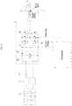
- FIG. 2 is a schematic representation of a solar pump system to which one embodiment of the present disclosure is applied.
- the solar pump system to which one embodiment of the present disclosure is applied may include a solar module 2, an electromagnetic compatibility (EMC) filter 3, a fuse 4, an inverter 5, a controller 1, a water pump 6, and a water tank 7.
- EMC electromagnetic compatibility
- the water pump 6 as a load for the inverter 5 is illustrated, but the present disclosure is not limited thereto.
- Various examples in which the energy generated by the solar module 2 is transferred to various loads via the inverter 5 may be implemented.
- the inverter 5 may include a boost converter 50, a DC link capacitor 51, an inverting module 52, and a voltage sensor 53.
- the solar module 2 may be an array of solar cells vertically and horizontally. In the solar module, electricity generated by individual solar cells may be simultaneously collected in the solar module to produce electric power.
- the EMC filter 3 minimizes an electromagnetic interference generated by the power applied from the solar module 2. This may prevent damage due to such electromagnetic interference.
- the EMC filter 3 may block a excessive current flow to the fuse 40 or inverter 5.
- the EMC filter 3 and the fuse 4 may be illustrative and may be merely examples.
- Various elements for eliminating the noise generated by the power input from the solar module 2 may be used in an exemplary embodiment of the solar pump system of the present disclosure.
- the DC voltage from which the noise is removed by the EMC filter 3 and the fuse 4 may be applied to the inverter 5.
- the DC voltage applied to the inverter 5 may be boosted by the boost converter 50.
- the boosted DC voltage may be stored in the DC link capacitor 51.
- the controller 1 generates a switching signal for controlling switching of a plurality of switching elements of the inverting module 52 of the inverter 5 based on the DC link voltage detected by a voltage sensor 53.
- the controller may then provide the switching signal to the inverting module 52. That is, under the control of the controller 1, an output frequency of the inverting module 52 of the inverter 5 may be determined. This will be described in detail later.
- a change in the DC link voltage of the inverter 5 varies with a quantity of the solar irradiation.
- the voltage variation is small.
- the voltage variation may become large.
- the water pump 6 may be driven by a AC voltage output from the inverting module 52 of the inverter 5. Thus, water drawn up by the water pump 6 may be stored in the water tank 7. The water transferred to the water tank 7 may be used as drinking water, industrial water, agricultural water, live-stock water, and the like.
- the maximum power may be tracked using only the DC link voltage of the inverter without requiring additional sensors. This may prevent an increase in the system stress due to the pulsation of the output frequency.
- the controller 1 in accordance with one embodiment of the present disclosure increases the output frequency of the inverter 2 when the DC link voltage is above or equal to a predetermined reference level. Further, when the output frequency is higher compared to the energy generated from the solar module 1 and thus the DC link voltage becomes smaller than the reference level, the controller 1 may back reduce the output frequency to prevent the DC link voltage from decreasing.
- the controller does not increase the output frequency immediately after the DC link voltage has been again sufficient when the controller 1 had decreased the output frequency. Rather, the controller stably raises the output frequency to an output frequency level at a time when the DC link voltage has been insufficient, and then determines a stability of the DC link voltage. When the controller 1 determines that the DC link voltage is stable, the controller performs a normal acceleration operation. The detailed operation of the controller 1 will be described with reference to the drawings.
- FIG. 3 is a flow chart describing an inverter-controlling method in accordance with one embodiment of the present disclosure.
- the controller 1 may periodically receive the DC link voltage from the voltage sensor 53 S41.
- the controller may determine whether the received DC link voltage is greater than or equal to the reference level or smaller than the reference level S42.
- the controller 1 may again determine whether the DC link voltage in a previous period is greater than or equal to or smaller than the reference level S43.
- the controller 1 may store an output frequency in the current period as a first output frequency S44, and decrease the output frequency S45. Then, the method may return. That is, when the DC link voltage decreases for the first time in the current period and becomes smaller than the reference level, the controller 1 stores the output frequency in the current period as the first output frequency S44, and then decreases the output frequency S45. Then, the method returns.
- Decreasing the output frequency means decreasing the output frequency by an amount corresponding to a decreasing slope in a discrete manner, or continuously. That is, the controller 1 may continuously decrease the output frequency according to the decreasing slope over a predetermined time based on a setting. Alternatively, the controller 1 may decrease the output frequency by subtracting discrete values corresponding to the decreasing slope from a previous output frequency in the previous period.
- the method may proceed to S45 which the controller reduces the output frequency.
- the method may proceed to S45 which the controller reduces the output frequency.
- the controller 1 transmits a PWM signal to gates of the plurality of the switching elements of the inverting module 52 of the inverter 5 to control on/off of the switching elements, such that the inverting module 52 outputs AC power. That is, when the controller 1 decreases the output frequency, the output frequency of the AC power synthesized by the inverting module 52 is decreased, and, thus, the output frequency of the AC power output from the inverting module 52 is decreased, so that the driving speed of the water pump 6 is slowed down.
- the controller 1 may check whether the output frequency has decreased in the previous period.
- the controller 1 may increment the output frequency by a frequency corresponding to a first slope S47.
- the method may return. That is, when the DC link voltage was greater than the reference level in the previous period, the controller 1 may increase the output frequency by the frequency corresponding to the first slope S47. Then, the method may return.
- Increasing the output frequency means that the output frequency of the AC power synthesized by the switching elements of the inverting module 52 is increased and thus the driving speed of the water pump 6 is increased.
- increasing the output frequency at the first slope may mean increasing the output frequency by an amount corresponding to the first slope continuously or discretely. That is, the output frequency may be increased according to the first slope continuously for a predetermined time based on a setting. Alternatively, the output frequency may increase by adding discrete values corresponding to the first slope to a previous output frequency in the previous period.
- the output frequency may be increased at a second slope smaller than the first slope at S47.
- controller 1 may check whether the output frequency increased at the second slope is greater than or equal to the first output frequency stored in S44. When the output frequency is greater than or equal to the first output frequency, the output frequency is fixed. When the output frequency is smaller than the first output frequency, the method returns.
- the controller 1 may determine whether the DC link voltage is stable for a predetermined time S51.
- the determination of whether or not the DC link voltage is stable may include determining a threshold range of a magnitude of the DC link voltage change, and determining that the DC link voltage is not stable when the change of the DC link voltage for a predetermined time is equal to or above the threshold range.
- the controller 1 may further include a memory.
- the controller 1 may clear a current state. That is, the output frequency decreased state may be cleared, and the stored first output frequency may be cleared.
- the controller does not increase the output frequency immediately after the DC link voltage has been sufficient when the controller 1 had decreased the output frequency due to the insufficiency in the DC link voltage; rather, the controller 1 stably raises (at a smaller slope) the output frequency to an output frequency level (first output frequency) at a time when the DC link voltage had been insufficient, and then determines a stability of the DC link voltage for the predetermined time; then, when the controller 1 determines that the DC link voltage is stable for the predetermined time, the controller performs a normal acceleration operation (with a higher slope).
- the frequency changes of the water pump 6 are frequent, resulting in the failure.
- the controller may increase the output frequency.
- the output frequency may be decreased by the controller to prevent the DC link voltage from further decreasing. This may allow the energy generated by the solar module 2 to be used at the maximum degree while the low voltage problem does not occur.
- the output frequency may be increased by the controller at a smaller slope that a slope at the sufficient state.
- the DC link voltage is used as the information for generating the inverter PMW output waveform for controlling the water pump 6 and as information for detecting the low voltage/high voltage.
- the increase and decrease of the DC link voltage is continuously checked, and, then, the output frequency changes based on the increase and decrease of the DC link voltage to prevent the abrupt change of the DC link voltage according to the solar irradiation quantity.
- the changes in the DC link voltage may be sensed without additional sensors, thereby to allow the power generated by the solar module to be used at a maximum level.
Landscapes
- Engineering & Computer Science (AREA)
- Power Engineering (AREA)
- Physics & Mathematics (AREA)
- General Physics & Mathematics (AREA)
- Life Sciences & Earth Sciences (AREA)
- Sustainable Development (AREA)
- Sustainable Energy (AREA)
- Electromagnetism (AREA)
- General Engineering & Computer Science (AREA)
- Mechanical Engineering (AREA)
- Radar, Positioning & Navigation (AREA)
- Automation & Control Theory (AREA)
- Computer Hardware Design (AREA)
- Inverter Devices (AREA)
- Control Of Electrical Variables (AREA)
- Supply And Distribution Of Alternating Current (AREA)
Applications Claiming Priority (1)
| Application Number | Priority Date | Filing Date | Title |
|---|---|---|---|
| KR1020180053452A KR101999183B1 (ko) | 2018-05-10 | 2018-05-10 | 인버터 제어방법 |
Publications (2)
| Publication Number | Publication Date |
|---|---|
| EP3567448A1 true EP3567448A1 (de) | 2019-11-13 |
| EP3567448B1 EP3567448B1 (de) | 2021-08-11 |
Family
ID=65493940
Family Applications (1)
| Application Number | Title | Priority Date | Filing Date |
|---|---|---|---|
| EP19157815.2A Active EP3567448B1 (de) | 2018-05-10 | 2019-02-18 | Verfahren zur steuerung eines wechselrichters in einem solarpumpensystem |
Country Status (6)
| Country | Link |
|---|---|
| US (1) | US10389296B1 (de) |
| EP (1) | EP3567448B1 (de) |
| JP (1) | JP6772312B2 (de) |
| KR (1) | KR101999183B1 (de) |
| CN (1) | CN110474556B (de) |
| ES (1) | ES2896020T3 (de) |
Families Citing this family (2)
| Publication number | Priority date | Publication date | Assignee | Title |
|---|---|---|---|---|
| DE102019129348A1 (de) * | 2019-10-30 | 2021-05-06 | Friedrich-Alexander-Universität Erlangen-Nürnberg | Anlage zur Aufbereitung von Wasser und Verfahren dazu |
| CN117365973B (zh) * | 2023-12-07 | 2024-02-09 | 四川省农业机械科学研究院 | 一种弱光弱信号区域太阳能提水方法及系统 |
Citations (1)
| Publication number | Priority date | Publication date | Assignee | Title |
|---|---|---|---|---|
| WO2011115952A1 (en) * | 2010-03-15 | 2011-09-22 | Solar Semiconductor, Inc. | Systems and methods for operating a solar direct pump |
Family Cites Families (16)
| Publication number | Priority date | Publication date | Assignee | Title |
|---|---|---|---|---|
| GB2176667B (en) * | 1985-06-11 | 1989-07-05 | Toshiba Kk | Electric motor running system employing a photovoltaic array |
| JPH0895655A (ja) * | 1991-04-26 | 1996-04-12 | Tonen Corp | 太陽電池駆動におけるインバータ制御方式 |
| JP3027891B2 (ja) * | 1993-02-02 | 2000-04-04 | 富士電機株式会社 | 可変速インバータの制御方法 |
| JP2000060179A (ja) * | 1998-08-04 | 2000-02-25 | Fuji Electric Co Ltd | ポンプ駆動用太陽光インバータの制御方法 |
| US6229278B1 (en) * | 1999-09-29 | 2001-05-08 | Rockwell Technologies, Llc | Voltage and current limiting method and apparatus for a voltage/frequency drive |
| CN101355319B (zh) * | 2008-09-17 | 2010-11-10 | 南京航空航天大学 | 一种提高电流控制型逆变器输出短路运行可靠性的方法 |
| US9042141B2 (en) * | 2013-02-07 | 2015-05-26 | Caterpillar Inc. | Control of energy storage system inverter system in a microgrid application |
| JP5731574B2 (ja) * | 2013-05-27 | 2015-06-10 | シャープ株式会社 | インバータ制御装置 |
| KR101830666B1 (ko) * | 2013-09-17 | 2018-02-21 | 엘에스산전 주식회사 | 전력 변환 장치 |
| CN103940045B (zh) * | 2014-04-22 | 2016-08-24 | 广东美的集团芜湖制冷设备有限公司 | 太阳能空调及其控制方法和控制装置 |
| KR101861889B1 (ko) * | 2014-06-10 | 2018-05-28 | 엘에스산전 주식회사 | 인버터의 순간 정전 보상 방법 |
| JP6546203B2 (ja) * | 2015-02-10 | 2019-07-17 | 株式会社東芝 | 電力変換装置の制御装置、制御プログラム及び電力変換装置 |
| KR102028328B1 (ko) * | 2015-04-14 | 2019-10-04 | 엘에스산전 주식회사 | 계통 연계형 인버터 제어장치 |
| KR101783121B1 (ko) * | 2016-01-18 | 2017-09-28 | 엘에스산전 주식회사 | 인버터 |
| ES2607253B2 (es) * | 2017-01-19 | 2018-03-01 | Universidad Politécnica de Madrid | Procedimiento y dispositivo de control para sistemas de bombeo fotovoltaico |
| CN107370187B (zh) * | 2017-09-08 | 2019-07-26 | 中南大学 | 一种光伏微电网系统和光伏微电网系统控制方法 |
-
2018
- 2018-05-10 KR KR1020180053452A patent/KR101999183B1/ko active Active
-
2019
- 2019-02-04 JP JP2019018185A patent/JP6772312B2/ja active Active
- 2019-02-18 ES ES19157815T patent/ES2896020T3/es active Active
- 2019-02-18 EP EP19157815.2A patent/EP3567448B1/de active Active
- 2019-02-22 US US16/283,071 patent/US10389296B1/en active Active
- 2019-03-01 CN CN201910156518.7A patent/CN110474556B/zh active Active
Patent Citations (1)
| Publication number | Priority date | Publication date | Assignee | Title |
|---|---|---|---|---|
| WO2011115952A1 (en) * | 2010-03-15 | 2011-09-22 | Solar Semiconductor, Inc. | Systems and methods for operating a solar direct pump |
Non-Patent Citations (3)
| Title |
|---|
| GUO HENG ET AL: "A Novel Maximum Power Point Tracking Strategy for Stand-alone Solar Pumping Systems", TRANSMISSION AND DISTRIBUTION CONFERENCE AND EXHIBITION: ASIA AND PACI FIC, 2005 IEEE/PES DALIAN, CHINA 15-18 AUG. 2005, 1 January 2005 (2005-01-01), Piscataway, NJ, USA, pages 1 - 5, XP055610571, ISBN: 978-0-7803-9114-7, DOI: 10.1109/TDC.2005.1546878 * |
| SONGBAI ZHANG ET AL: "Optimization of MPPT Step Size in Stand-alone Solar Pumping Systems", 2006 IEEE POWER ENGINEERING SOCIETY GENERAL MEETING; 18-22 JUNE 2006; MONTREAL, QUE., CANADA, IEEE, PISCATAWAY, NJ, USA, 18 June 2006 (2006-06-18), pages 1 - 6, XP010942802, ISBN: 978-1-4244-0493-3 * |
| UTKARSH SHARMA ET AL: "Single Stage Solar PV Array Fed Field Oriented Controlled Induction Motor Drive for Water Pump", NPEC 2015: NATIONAL POWER ELECTRONICS CONFERENCE 2015, 21 December 2015 (2015-12-21), XP055610596, Retrieved from the Internet <URL:https://www.ee.iitb.ac.in/npec/Papers/Program/NPEC_2015_paper_103.pdf> [retrieved on 20190802] * |
Also Published As
| Publication number | Publication date |
|---|---|
| CN110474556B (zh) | 2021-05-14 |
| KR101999183B1 (ko) | 2019-07-11 |
| EP3567448B1 (de) | 2021-08-11 |
| CN110474556A (zh) | 2019-11-19 |
| US10389296B1 (en) | 2019-08-20 |
| JP6772312B2 (ja) | 2020-10-21 |
| JP2019198211A (ja) | 2019-11-14 |
| ES2896020T3 (es) | 2022-02-23 |
Similar Documents
| Publication | Publication Date | Title |
|---|---|---|
| JP5726555B2 (ja) | 太陽光発電システム | |
| US8450883B2 (en) | Maximum power point tracking control apparatus for solar battery | |
| CN108233406B (zh) | 太阳能泵系统和用于控制太阳能泵系统的方法 | |
| JP5821087B2 (ja) | インバータの動作制御のための方法 | |
| EP2824533B1 (de) | Photovoltaiksystem | |
| CN105723519B (zh) | 用于运行具有储能器的光伏设备的方法以及用于连接储能器的双向转换器 | |
| KR102087063B1 (ko) | 전력 변환 동안 개선된 버스트 모드를 위한 방법 및 장치 | |
| EP3567448B1 (de) | Verfahren zur steuerung eines wechselrichters in einem solarpumpensystem | |
| CN115411771A (zh) | 一种光伏发电系统和光伏发电系统的控制方法 | |
| JP2012161189A (ja) | 蓄電池への太陽電池電力の充放電制御方法 | |
| KR20190036914A (ko) | Dc-dc 전압 레귤레이터를 이용한 태양광전원의 효율향상 장치 | |
| CN113767537A (zh) | 电力控制装置、电力控制装置的控制方法、分布式发电系统 | |
| CN106104956A (zh) | 用于从光伏模块取出电能的方法和设备 | |
| JP7022942B2 (ja) | 電力変換システム、電力変換装置 | |
| JP2014199477A (ja) | 発電制御装置及び発電制御方法 | |
| US9541587B2 (en) | Inverting apparatus for avoiding misjudgement of maximum power point tracking operation and control method thereof | |
| CN105518965B (zh) | 一种光伏并网控制方法及光伏并网系统 | |
| CN109672166B (zh) | 功率优化系统及其优化方法 | |
| US20150142189A1 (en) | Power generation control system, method and non-transitory computer readable storage medium of the same | |
| KR101761606B1 (ko) | 태양광 발전 시스템의 최대전력점 추종 방법 | |
| JP2019012380A (ja) | 太陽光発電システム | |
| Tolentino et al. | Efficiency improvement of commercially available mppt controllers using boost converter | |
| JP2022120406A (ja) | 電源システム | |
| Hattori et al. | A Control Method for a PV System with a Capacitor Connected to a PCS Input Terminal | |
| KR20150040168A (ko) | 전력변환장치 및 에너지 저장 시스템 |
Legal Events
| Date | Code | Title | Description |
|---|---|---|---|
| PUAI | Public reference made under article 153(3) epc to a published international application that has entered the european phase |
Free format text: ORIGINAL CODE: 0009012 |
|
| STAA | Information on the status of an ep patent application or granted ep patent |
Free format text: STATUS: THE APPLICATION HAS BEEN PUBLISHED |
|
| AK | Designated contracting states |
Kind code of ref document: A1 Designated state(s): AL AT BE BG CH CY CZ DE DK EE ES FI FR GB GR HR HU IE IS IT LI LT LU LV MC MK MT NL NO PL PT RO RS SE SI SK SM TR |
|
| AX | Request for extension of the european patent |
Extension state: BA ME |
|
| STAA | Information on the status of an ep patent application or granted ep patent |
Free format text: STATUS: REQUEST FOR EXAMINATION WAS MADE |
|
| 17P | Request for examination filed |
Effective date: 20200513 |
|
| RBV | Designated contracting states (corrected) |
Designated state(s): AL AT BE BG CH CY CZ DE DK EE ES FI FR GB GR HR HU IE IS IT LI LT LU LV MC MK MT NL NO PL PT RO RS SE SI SK SM TR |
|
| GRAP | Despatch of communication of intention to grant a patent |
Free format text: ORIGINAL CODE: EPIDOSNIGR1 |
|
| STAA | Information on the status of an ep patent application or granted ep patent |
Free format text: STATUS: GRANT OF PATENT IS INTENDED |
|
| INTG | Intention to grant announced |
Effective date: 20210406 |
|
| GRAS | Grant fee paid |
Free format text: ORIGINAL CODE: EPIDOSNIGR3 |
|
| GRAA | (expected) grant |
Free format text: ORIGINAL CODE: 0009210 |
|
| STAA | Information on the status of an ep patent application or granted ep patent |
Free format text: STATUS: THE PATENT HAS BEEN GRANTED |
|
| AK | Designated contracting states |
Kind code of ref document: B1 Designated state(s): AL AT BE BG CH CY CZ DE DK EE ES FI FR GB GR HR HU IE IS IT LI LT LU LV MC MK MT NL NO PL PT RO RS SE SI SK SM TR |
|
| REG | Reference to a national code |
Ref country code: CH Ref legal event code: EP |
|
| REG | Reference to a national code |
Ref country code: DE Ref legal event code: R096 Ref document number: 602019006691 Country of ref document: DE |
|
| REG | Reference to a national code |
Ref country code: IE Ref legal event code: FG4D Ref country code: AT Ref legal event code: REF Ref document number: 1420021 Country of ref document: AT Kind code of ref document: T Effective date: 20210915 |
|
| REG | Reference to a national code |
Ref country code: LT Ref legal event code: MG9D |
|
| REG | Reference to a national code |
Ref country code: NL Ref legal event code: MP Effective date: 20210811 |
|
| REG | Reference to a national code |
Ref country code: AT Ref legal event code: MK05 Ref document number: 1420021 Country of ref document: AT Kind code of ref document: T Effective date: 20210811 |
|
| PG25 | Lapsed in a contracting state [announced via postgrant information from national office to epo] |
Ref country code: HR Free format text: LAPSE BECAUSE OF FAILURE TO SUBMIT A TRANSLATION OF THE DESCRIPTION OR TO PAY THE FEE WITHIN THE PRESCRIBED TIME-LIMIT Effective date: 20210811 Ref country code: NO Free format text: LAPSE BECAUSE OF FAILURE TO SUBMIT A TRANSLATION OF THE DESCRIPTION OR TO PAY THE FEE WITHIN THE PRESCRIBED TIME-LIMIT Effective date: 20211111 Ref country code: PT Free format text: LAPSE BECAUSE OF FAILURE TO SUBMIT A TRANSLATION OF THE DESCRIPTION OR TO PAY THE FEE WITHIN THE PRESCRIBED TIME-LIMIT Effective date: 20211213 Ref country code: BG Free format text: LAPSE BECAUSE OF FAILURE TO SUBMIT A TRANSLATION OF THE DESCRIPTION OR TO PAY THE FEE WITHIN THE PRESCRIBED TIME-LIMIT Effective date: 20211111 Ref country code: AT Free format text: LAPSE BECAUSE OF FAILURE TO SUBMIT A TRANSLATION OF THE DESCRIPTION OR TO PAY THE FEE WITHIN THE PRESCRIBED TIME-LIMIT Effective date: 20210811 Ref country code: LT Free format text: LAPSE BECAUSE OF FAILURE TO SUBMIT A TRANSLATION OF THE DESCRIPTION OR TO PAY THE FEE WITHIN THE PRESCRIBED TIME-LIMIT Effective date: 20210811 Ref country code: SE Free format text: LAPSE BECAUSE OF FAILURE TO SUBMIT A TRANSLATION OF THE DESCRIPTION OR TO PAY THE FEE WITHIN THE PRESCRIBED TIME-LIMIT Effective date: 20210811 Ref country code: RS Free format text: LAPSE BECAUSE OF FAILURE TO SUBMIT A TRANSLATION OF THE DESCRIPTION OR TO PAY THE FEE WITHIN THE PRESCRIBED TIME-LIMIT Effective date: 20210811 Ref country code: FI Free format text: LAPSE BECAUSE OF FAILURE TO SUBMIT A TRANSLATION OF THE DESCRIPTION OR TO PAY THE FEE WITHIN THE PRESCRIBED TIME-LIMIT Effective date: 20210811 |
|
| REG | Reference to a national code |
Ref country code: ES Ref legal event code: FG2A Ref document number: 2896020 Country of ref document: ES Kind code of ref document: T3 Effective date: 20220223 |
|
| PG25 | Lapsed in a contracting state [announced via postgrant information from national office to epo] |
Ref country code: PL Free format text: LAPSE BECAUSE OF FAILURE TO SUBMIT A TRANSLATION OF THE DESCRIPTION OR TO PAY THE FEE WITHIN THE PRESCRIBED TIME-LIMIT Effective date: 20210811 Ref country code: LV Free format text: LAPSE BECAUSE OF FAILURE TO SUBMIT A TRANSLATION OF THE DESCRIPTION OR TO PAY THE FEE WITHIN THE PRESCRIBED TIME-LIMIT Effective date: 20210811 Ref country code: GR Free format text: LAPSE BECAUSE OF FAILURE TO SUBMIT A TRANSLATION OF THE DESCRIPTION OR TO PAY THE FEE WITHIN THE PRESCRIBED TIME-LIMIT Effective date: 20211112 |
|
| PG25 | Lapsed in a contracting state [announced via postgrant information from national office to epo] |
Ref country code: NL Free format text: LAPSE BECAUSE OF FAILURE TO SUBMIT A TRANSLATION OF THE DESCRIPTION OR TO PAY THE FEE WITHIN THE PRESCRIBED TIME-LIMIT Effective date: 20210811 |
|
| PG25 | Lapsed in a contracting state [announced via postgrant information from national office to epo] |
Ref country code: DK Free format text: LAPSE BECAUSE OF FAILURE TO SUBMIT A TRANSLATION OF THE DESCRIPTION OR TO PAY THE FEE WITHIN THE PRESCRIBED TIME-LIMIT Effective date: 20210811 |
|
| REG | Reference to a national code |
Ref country code: DE Ref legal event code: R097 Ref document number: 602019006691 Country of ref document: DE |
|
| PG25 | Lapsed in a contracting state [announced via postgrant information from national office to epo] |
Ref country code: SM Free format text: LAPSE BECAUSE OF FAILURE TO SUBMIT A TRANSLATION OF THE DESCRIPTION OR TO PAY THE FEE WITHIN THE PRESCRIBED TIME-LIMIT Effective date: 20210811 Ref country code: SK Free format text: LAPSE BECAUSE OF FAILURE TO SUBMIT A TRANSLATION OF THE DESCRIPTION OR TO PAY THE FEE WITHIN THE PRESCRIBED TIME-LIMIT Effective date: 20210811 Ref country code: RO Free format text: LAPSE BECAUSE OF FAILURE TO SUBMIT A TRANSLATION OF THE DESCRIPTION OR TO PAY THE FEE WITHIN THE PRESCRIBED TIME-LIMIT Effective date: 20210811 Ref country code: EE Free format text: LAPSE BECAUSE OF FAILURE TO SUBMIT A TRANSLATION OF THE DESCRIPTION OR TO PAY THE FEE WITHIN THE PRESCRIBED TIME-LIMIT Effective date: 20210811 Ref country code: CZ Free format text: LAPSE BECAUSE OF FAILURE TO SUBMIT A TRANSLATION OF THE DESCRIPTION OR TO PAY THE FEE WITHIN THE PRESCRIBED TIME-LIMIT Effective date: 20210811 Ref country code: AL Free format text: LAPSE BECAUSE OF FAILURE TO SUBMIT A TRANSLATION OF THE DESCRIPTION OR TO PAY THE FEE WITHIN THE PRESCRIBED TIME-LIMIT Effective date: 20210811 |
|
| PLBE | No opposition filed within time limit |
Free format text: ORIGINAL CODE: 0009261 |
|
| STAA | Information on the status of an ep patent application or granted ep patent |
Free format text: STATUS: NO OPPOSITION FILED WITHIN TIME LIMIT |
|
| 26N | No opposition filed |
Effective date: 20220512 |
|
| PG25 | Lapsed in a contracting state [announced via postgrant information from national office to epo] |
Ref country code: SI Free format text: LAPSE BECAUSE OF FAILURE TO SUBMIT A TRANSLATION OF THE DESCRIPTION OR TO PAY THE FEE WITHIN THE PRESCRIBED TIME-LIMIT Effective date: 20210811 |
|
| PG25 | Lapsed in a contracting state [announced via postgrant information from national office to epo] |
Ref country code: MC Free format text: LAPSE BECAUSE OF FAILURE TO SUBMIT A TRANSLATION OF THE DESCRIPTION OR TO PAY THE FEE WITHIN THE PRESCRIBED TIME-LIMIT Effective date: 20210811 |
|
| REG | Reference to a national code |
Ref country code: CH Ref legal event code: PL |
|
| REG | Reference to a national code |
Ref country code: BE Ref legal event code: MM Effective date: 20220228 |
|
| PG25 | Lapsed in a contracting state [announced via postgrant information from national office to epo] |
Ref country code: LU Free format text: LAPSE BECAUSE OF NON-PAYMENT OF DUE FEES Effective date: 20220218 |
|
| PG25 | Lapsed in a contracting state [announced via postgrant information from national office to epo] |
Ref country code: FR Free format text: LAPSE BECAUSE OF NON-PAYMENT OF DUE FEES Effective date: 20220228 |
|
| PG25 | Lapsed in a contracting state [announced via postgrant information from national office to epo] |
Ref country code: LI Free format text: LAPSE BECAUSE OF NON-PAYMENT OF DUE FEES Effective date: 20220228 Ref country code: IE Free format text: LAPSE BECAUSE OF NON-PAYMENT OF DUE FEES Effective date: 20220218 Ref country code: CH Free format text: LAPSE BECAUSE OF NON-PAYMENT OF DUE FEES Effective date: 20220228 |
|
| PG25 | Lapsed in a contracting state [announced via postgrant information from national office to epo] |
Ref country code: BE Free format text: LAPSE BECAUSE OF NON-PAYMENT OF DUE FEES Effective date: 20220228 |
|
| P01 | Opt-out of the competence of the unified patent court (upc) registered |
Effective date: 20230625 |
|
| PG25 | Lapsed in a contracting state [announced via postgrant information from national office to epo] |
Ref country code: MK Free format text: LAPSE BECAUSE OF FAILURE TO SUBMIT A TRANSLATION OF THE DESCRIPTION OR TO PAY THE FEE WITHIN THE PRESCRIBED TIME-LIMIT Effective date: 20210811 Ref country code: CY Free format text: LAPSE BECAUSE OF FAILURE TO SUBMIT A TRANSLATION OF THE DESCRIPTION OR TO PAY THE FEE WITHIN THE PRESCRIBED TIME-LIMIT Effective date: 20210811 |
|
| PG25 | Lapsed in a contracting state [announced via postgrant information from national office to epo] |
Ref country code: HU Free format text: LAPSE BECAUSE OF FAILURE TO SUBMIT A TRANSLATION OF THE DESCRIPTION OR TO PAY THE FEE WITHIN THE PRESCRIBED TIME-LIMIT; INVALID AB INITIO Effective date: 20190218 |
|
| PG25 | Lapsed in a contracting state [announced via postgrant information from national office to epo] |
Ref country code: TR Free format text: LAPSE BECAUSE OF FAILURE TO SUBMIT A TRANSLATION OF THE DESCRIPTION OR TO PAY THE FEE WITHIN THE PRESCRIBED TIME-LIMIT Effective date: 20210811 |
|
| PG25 | Lapsed in a contracting state [announced via postgrant information from national office to epo] |
Ref country code: MT Free format text: LAPSE BECAUSE OF FAILURE TO SUBMIT A TRANSLATION OF THE DESCRIPTION OR TO PAY THE FEE WITHIN THE PRESCRIBED TIME-LIMIT Effective date: 20210811 |
|
| PGFP | Annual fee paid to national office [announced via postgrant information from national office to epo] |
Ref country code: GB Payment date: 20251208 Year of fee payment: 8 |
|
| PGFP | Annual fee paid to national office [announced via postgrant information from national office to epo] |
Ref country code: ES Payment date: 20260324 Year of fee payment: 8 |
|
| PGFP | Annual fee paid to national office [announced via postgrant information from national office to epo] |
Ref country code: DE Payment date: 20251208 Year of fee payment: 8 |
|
| PGFP | Annual fee paid to national office [announced via postgrant information from national office to epo] |
Ref country code: IT Payment date: 20251209 Year of fee payment: 8 |