EP3566938A1 - Manivelle de bicyclette et pédalier correspondant - Google Patents
Manivelle de bicyclette et pédalier correspondant Download PDFInfo
- Publication number
- EP3566938A1 EP3566938A1 EP19173645.3A EP19173645A EP3566938A1 EP 3566938 A1 EP3566938 A1 EP 3566938A1 EP 19173645 A EP19173645 A EP 19173645A EP 3566938 A1 EP3566938 A1 EP 3566938A1
- Authority
- EP
- European Patent Office
- Prior art keywords
- crankarm
- power supply
- battery power
- recharging
- supply unit
- Prior art date
- Legal status (The legal status is an assumption and is not a legal conclusion. Google has not performed a legal analysis and makes no representation as to the accuracy of the status listed.)
- Pending
Links
Images


Classifications
-
- B—PERFORMING OPERATIONS; TRANSPORTING
- B60—VEHICLES IN GENERAL
- B60L—PROPULSION OF ELECTRICALLY-PROPELLED VEHICLES; SUPPLYING ELECTRIC POWER FOR AUXILIARY EQUIPMENT OF ELECTRICALLY-PROPELLED VEHICLES; ELECTRODYNAMIC BRAKE SYSTEMS FOR VEHICLES IN GENERAL; MAGNETIC SUSPENSION OR LEVITATION FOR VEHICLES; MONITORING OPERATING VARIABLES OF ELECTRICALLY-PROPELLED VEHICLES; ELECTRIC SAFETY DEVICES FOR ELECTRICALLY-PROPELLED VEHICLES
- B60L53/00—Methods of charging batteries, specially adapted for electric vehicles; Charging stations or on-board charging equipment therefor; Exchange of energy storage elements in electric vehicles
-
- B—PERFORMING OPERATIONS; TRANSPORTING
- B62—LAND VEHICLES FOR TRAVELLING OTHERWISE THAN ON RAILS
- B62J—CYCLE SADDLES OR SEATS; AUXILIARY DEVICES OR ACCESSORIES SPECIALLY ADAPTED TO CYCLES AND NOT OTHERWISE PROVIDED FOR, e.g. ARTICLE CARRIERS OR CYCLE PROTECTORS
- B62J99/00—Subject matter not provided for in other groups of this subclass
-
- B—PERFORMING OPERATIONS; TRANSPORTING
- B62—LAND VEHICLES FOR TRAVELLING OTHERWISE THAN ON RAILS
- B62M—RIDER PROPULSION OF WHEELED VEHICLES OR SLEDGES; POWERED PROPULSION OF SLEDGES OR SINGLE-TRACK CYCLES; TRANSMISSIONS SPECIALLY ADAPTED FOR SUCH VEHICLES
- B62M3/00—Construction of cranks operated by hand or foot
- B62M3/16—Accessories
-
- B—PERFORMING OPERATIONS; TRANSPORTING
- B62—LAND VEHICLES FOR TRAVELLING OTHERWISE THAN ON RAILS
- B62M—RIDER PROPULSION OF WHEELED VEHICLES OR SLEDGES; POWERED PROPULSION OF SLEDGES OR SINGLE-TRACK CYCLES; TRANSMISSIONS SPECIALLY ADAPTED FOR SUCH VEHICLES
- B62M6/00—Rider propulsion of wheeled vehicles with additional source of power, e.g. combustion engine or electric motor
- B62M6/40—Rider propelled cycles with auxiliary electric motor
-
- B—PERFORMING OPERATIONS; TRANSPORTING
- B62—LAND VEHICLES FOR TRAVELLING OTHERWISE THAN ON RAILS
- B62M—RIDER PROPULSION OF WHEELED VEHICLES OR SLEDGES; POWERED PROPULSION OF SLEDGES OR SINGLE-TRACK CYCLES; TRANSMISSIONS SPECIALLY ADAPTED FOR SUCH VEHICLES
- B62M6/00—Rider propulsion of wheeled vehicles with additional source of power, e.g. combustion engine or electric motor
- B62M6/80—Accessories, e.g. power sources; Arrangements thereof
- B62M6/90—Batteries
-
- H—ELECTRICITY
- H01—ELECTRIC ELEMENTS
- H01R—ELECTRICALLY-CONDUCTIVE CONNECTIONS; STRUCTURAL ASSOCIATIONS OF A PLURALITY OF MUTUALLY-INSULATED ELECTRICAL CONNECTING ELEMENTS; COUPLING DEVICES; CURRENT COLLECTORS
- H01R13/00—Details of coupling devices of the kinds covered by groups H01R12/70 or H01R24/00 - H01R33/00
- H01R13/02—Contact members
- H01R13/22—Contacts for co-operating by abutting
-
- H—ELECTRICITY
- H01—ELECTRIC ELEMENTS
- H01R—ELECTRICALLY-CONDUCTIVE CONNECTIONS; STRUCTURAL ASSOCIATIONS OF A PLURALITY OF MUTUALLY-INSULATED ELECTRICAL CONNECTING ELEMENTS; COUPLING DEVICES; CURRENT COLLECTORS
- H01R13/00—Details of coupling devices of the kinds covered by groups H01R12/70 or H01R24/00 - H01R33/00
- H01R13/62—Means for facilitating engagement or disengagement of coupling parts or for holding them in engagement
- H01R13/6205—Two-part coupling devices held in engagement by a magnet
-
- H—ELECTRICITY
- H02—GENERATION; CONVERSION OR DISTRIBUTION OF ELECTRIC POWER
- H02J—CIRCUIT ARRANGEMENTS OR SYSTEMS FOR SUPPLYING OR DISTRIBUTING ELECTRIC POWER; SYSTEMS FOR STORING ELECTRIC ENERGY
- H02J7/00—Circuit arrangements for charging or depolarising batteries or for supplying loads from batteries
- H02J7/0013—Circuit arrangements for charging or depolarising batteries or for supplying loads from batteries acting upon several batteries simultaneously or sequentially
-
- H—ELECTRICITY
- H02—GENERATION; CONVERSION OR DISTRIBUTION OF ELECTRIC POWER
- H02J—CIRCUIT ARRANGEMENTS OR SYSTEMS FOR SUPPLYING OR DISTRIBUTING ELECTRIC POWER; SYSTEMS FOR STORING ELECTRIC ENERGY
- H02J7/00—Circuit arrangements for charging or depolarising batteries or for supplying loads from batteries
- H02J7/0042—Circuit arrangements for charging or depolarising batteries or for supplying loads from batteries characterised by the mechanical construction
- H02J7/0045—Circuit arrangements for charging or depolarising batteries or for supplying loads from batteries characterised by the mechanical construction concerning the insertion or the connection of the batteries
-
- B—PERFORMING OPERATIONS; TRANSPORTING
- B60—VEHICLES IN GENERAL
- B60L—PROPULSION OF ELECTRICALLY-PROPELLED VEHICLES; SUPPLYING ELECTRIC POWER FOR AUXILIARY EQUIPMENT OF ELECTRICALLY-PROPELLED VEHICLES; ELECTRODYNAMIC BRAKE SYSTEMS FOR VEHICLES IN GENERAL; MAGNETIC SUSPENSION OR LEVITATION FOR VEHICLES; MONITORING OPERATING VARIABLES OF ELECTRICALLY-PROPELLED VEHICLES; ELECTRIC SAFETY DEVICES FOR ELECTRICALLY-PROPELLED VEHICLES
- B60L2200/00—Type of vehicles
- B60L2200/12—Bikes
-
- B—PERFORMING OPERATIONS; TRANSPORTING
- B62—LAND VEHICLES FOR TRAVELLING OTHERWISE THAN ON RAILS
- B62J—CYCLE SADDLES OR SEATS; AUXILIARY DEVICES OR ACCESSORIES SPECIALLY ADAPTED TO CYCLES AND NOT OTHERWISE PROVIDED FOR, e.g. ARTICLE CARRIERS OR CYCLE PROTECTORS
- B62J45/00—Electrical equipment arrangements specially adapted for use as accessories on cycles, not otherwise provided for
- B62J45/40—Sensor arrangements; Mounting thereof
- B62J45/41—Sensor arrangements; Mounting thereof characterised by the type of sensor
- B62J45/411—Torque sensors
-
- B—PERFORMING OPERATIONS; TRANSPORTING
- B62—LAND VEHICLES FOR TRAVELLING OTHERWISE THAN ON RAILS
- B62J—CYCLE SADDLES OR SEATS; AUXILIARY DEVICES OR ACCESSORIES SPECIALLY ADAPTED TO CYCLES AND NOT OTHERWISE PROVIDED FOR, e.g. ARTICLE CARRIERS OR CYCLE PROTECTORS
- B62J45/00—Electrical equipment arrangements specially adapted for use as accessories on cycles, not otherwise provided for
- B62J45/40—Sensor arrangements; Mounting thereof
- B62J45/42—Sensor arrangements; Mounting thereof characterised by mounting
- B62J45/421—Sensor arrangements; Mounting thereof characterised by mounting at the pedal crank
-
- H—ELECTRICITY
- H01—ELECTRIC ELEMENTS
- H01R—ELECTRICALLY-CONDUCTIVE CONNECTIONS; STRUCTURAL ASSOCIATIONS OF A PLURALITY OF MUTUALLY-INSULATED ELECTRICAL CONNECTING ELEMENTS; COUPLING DEVICES; CURRENT COLLECTORS
- H01R2201/00—Connectors or connections adapted for particular applications
- H01R2201/26—Connectors or connections adapted for particular applications for vehicles
-
- Y—GENERAL TAGGING OF NEW TECHNOLOGICAL DEVELOPMENTS; GENERAL TAGGING OF CROSS-SECTIONAL TECHNOLOGIES SPANNING OVER SEVERAL SECTIONS OF THE IPC; TECHNICAL SUBJECTS COVERED BY FORMER USPC CROSS-REFERENCE ART COLLECTIONS [XRACs] AND DIGESTS
- Y02—TECHNOLOGIES OR APPLICATIONS FOR MITIGATION OR ADAPTATION AGAINST CLIMATE CHANGE
- Y02T—CLIMATE CHANGE MITIGATION TECHNOLOGIES RELATED TO TRANSPORTATION
- Y02T10/00—Road transport of goods or passengers
- Y02T10/60—Other road transportation technologies with climate change mitigation effect
- Y02T10/70—Energy storage systems for electromobility, e.g. batteries
-
- Y—GENERAL TAGGING OF NEW TECHNOLOGICAL DEVELOPMENTS; GENERAL TAGGING OF CROSS-SECTIONAL TECHNOLOGIES SPANNING OVER SEVERAL SECTIONS OF THE IPC; TECHNICAL SUBJECTS COVERED BY FORMER USPC CROSS-REFERENCE ART COLLECTIONS [XRACs] AND DIGESTS
- Y02—TECHNOLOGIES OR APPLICATIONS FOR MITIGATION OR ADAPTATION AGAINST CLIMATE CHANGE
- Y02T—CLIMATE CHANGE MITIGATION TECHNOLOGIES RELATED TO TRANSPORTATION
- Y02T10/00—Road transport of goods or passengers
- Y02T10/60—Other road transportation technologies with climate change mitigation effect
- Y02T10/7072—Electromobility specific charging systems or methods for batteries, ultracapacitors, supercapacitors or double-layer capacitors
-
- Y—GENERAL TAGGING OF NEW TECHNOLOGICAL DEVELOPMENTS; GENERAL TAGGING OF CROSS-SECTIONAL TECHNOLOGIES SPANNING OVER SEVERAL SECTIONS OF THE IPC; TECHNICAL SUBJECTS COVERED BY FORMER USPC CROSS-REFERENCE ART COLLECTIONS [XRACs] AND DIGESTS
- Y02—TECHNOLOGIES OR APPLICATIONS FOR MITIGATION OR ADAPTATION AGAINST CLIMATE CHANGE
- Y02T—CLIMATE CHANGE MITIGATION TECHNOLOGIES RELATED TO TRANSPORTATION
- Y02T90/00—Enabling technologies or technologies with a potential or indirect contribution to GHG emissions mitigation
- Y02T90/10—Technologies relating to charging of electric vehicles
- Y02T90/14—Plug-in electric vehicles
Definitions
- the invention relates in general to the field of bicycles.
- Bicycles are increasingly equipped with one or more electrical/electronic systems.
- the battery power supply units that supply the electrical/electronic components of the system can be replaceable, but it is more advantageous and practical to provide for battery power supply units rechargeable on-board.
- EP1978342A2 discloses an instrument-equipped bicycle component comprising a detection unit of at least one parameter representative of a stress imparted upon said component.
- a crankset - therein called bottom bracket assembly - and a detection unit associated with the bottom bracket shaft are described.
- the detection unit is supplied by a battery housed in a cavity of the bottom bracket shaft.
- the battery can be rechargeable, for example by induction. The recharging of the battery takes place by means of a suitable battery charger that is inserted in a seat made on the battery.
- US2017/0247078A1 discloses an electrical unit for a bicycle crankset, the bicycle electrical unit comprising a housing configured to be mounted on a crankarm and a recharging port provided on the housing, in particular of the USB type. Electronic components of the electrical unit are supplied by a battery power supply unit housed in the same housing or inside the bottom bracket spindle.
- the housing is mounted on a sprocket mounting portion of the crankarm, in particular radially - with reference to the rotation axis of the crankarm - between two adjacent sprocket mounting arms, through projecting attachment parts inserted in corresponding recesses made on the two sprocket mounting arms; on the bottom of such recesses or close thereto a passage hole for electrical cables is made; the housing is then screwed to the crankarm.
- the housing has a curved outer profile, so that when it is mounted it is arranged circumferentially between two sprocket mounting arms. The solution described in the document is therefore only applicable to the crankarm on the transmission side.
- the expression “on the transmission side” hereinafter will sometimes be simplified by the specific term “on the chain side” and sometimes further simplified by the specific term “right”, a belt transmission and also a left crankarm in the case of atypical mounting of the transmission being anyway meant to be encompassed.
- the expression “on the side opposite to the transmission side” will sometimes be simplified to "on the side opposite to the chain side” and sometimes further simplified by the specific term “left”, a belt transmission and also a right crankarm in the case of atypical mounting of the transmission being anyway meant to be encompassed.
- the housing of this document projects with respect to the spider legs between which it is mounted, unbalancing the crankarm in terms of aerodynamics and appearance.
- the housing is arranged between the spider and the chainrings, therefore requiring the dismounting of the latter, and not being suitable for chainrings made as one piece with the crankarm.
- this solution is not proper for a crankarm made of composite material comprising structural fiber incorporated in a polymeric matrix.
- the recharging port turns out to be in a position that is hard to reach for the insertion of the recharging cable, and that can be dangerous for the fingers; at the same time the recharging port is particularly exposed to the chain grease.
- the technical problem at the basis of the invention is to provide an alternative solution to those known for recharging a battery power supply unit.
- the invention relates to a crankarm comprising a main body, or arm region, extending between a rotation axis and a pedal axis of the crankarm, comprising a recharging port for a battery power supply unit, characterized in that said recharging port is made at a face of the main body.
- the crankarm comprises a plurality of spider legs (wholly indicated as spider) that extend radially, at a pivot end of the crankarm, about the rotation axis.
- spider legs wholly indicated as spider
- the recharging port is substantially flush with the rest of the outer surface of the main body of the crankarm.
- the recharging port substantially does not project from the main body, giving a good result in terms of aerodynamics and appearance, and is more protected from impacts.
- said battery power supply unit is supported by the crankarm itself.
- connection cables between the battery power supply unit and the recharging port follow a path of minimum length, and problems of connection between components that are physically separable from one another or even in reciprocal motion are avoided.
- the battery power supply unit is housed in a cavity inside the crankarm.
- the cavity is closed by a cover, more preferably by a watertight cover.
- the cover is glued along its edge to the crankarm.
- the recharging port is made at the cover.
- the battery power supply unit is fixed on an outer surface of the crankarm.
- Such a configuration although being less advantageous in terms of appearance and aerodynamics, is more advantageous in the case of replacement of the battery power supply unit, for example in the case of failures.
- the recharging port is made at a proximal face of the main body.
- proximal face of the crankarm the face that, in the mounted condition, faces the frame is meant to be indicated; under distal face of the crankarm, the face opposite the proximal face is meant to be indicated.
- the recharging port is less visible from the outside of the bicycle, with the result of a better appearance of the crankarm and of the bicycle as a whole; moreover, it is not subject to friction with the foot of the cyclist.
- the battery power supply unit is supported by another component of the crankset.
- the battery power supply unit is housed in the other crankarm or in a cavity of the bottom bracket spindle.
- the battery power supply unit is housed in a cavity of the bottom bracket spindle, the battery power supply unit can be more easily used to supply electrical/electronic components on both of the crankarms. Moreover, a space that is otherwise unused, inside the bottom bracket spindle, is advantageously exploited.
- the latter can power one or more electrical/electronic components coupled with the crankarm itself, in particular housed on or in the crankarm itself, or coupled with other components of the bicycle transmission.
- the recharging port comprises two electrical contacts for connection with a recharging device comprising two matched contacts, which in their turn are powered by an external source, wherein the contacts of the recharging port are of the flush type and wherein there is provided for: (i) at least one magnet, preferably a pair of magnets, at the recharging port for magnetic matching with a corresponding magnet(s) or metallic element(s) of the recharging device, or (ii) at least one metallic element, preferably a pair of metallic elements, at the recharging port for magnetic matching with at least one magnet, preferably a pair of magnets, of the recharging device.
- the external source can be the mains, in which case the recharging device comprises a plug, or a hardware component, in which case the recharging device comprises a suitable connector, in particular a USB or miniUSB connector.
- the recharging port comprises a pair of reversible contacts, namely recharging can take place irrespective of the orientation of the two contacts of the recharging device with respect to the two contacts of the recharging port.
- the battery power supply unit comprises one or more button cells.
- crankarm is made at least in part of composite material comprising structural fiber incorporated in a polymeric matrix.
- the structural fiber is selected from the group consisting of carbon fibers, glass fibers, boron fibers, synthetic fibers, ceramic fibers and combinations thereof.
- the synthetic fibers comprise polyoxazole fibers, for example Zylon®, ultra high molecular weight polyethylene fibers, for example Dyneema®, aramid fibers, for example kevlar fibers and combinations thereof.
- polyoxazole fibers for example Zylon®
- ultra high molecular weight polyethylene fibers for example Dyneema®
- aramid fibers for example kevlar fibers and combinations thereof.
- the invention in another aspect, relates to a bicycle crankset comprising a first crankarm, in particular on the transmission side, and a second crankarm, in particular on the side opposite to the transmission side, each of said crankarms comprising a main body extending between a rotation axis and a pedal axis, said first crankarm comprising a first recharging port for a battery power supply unit, characterized in that said first recharging port is made at a face of the main body of said first crankarm.
- the crankset comprises a first and a second battery power supply unit, and a second recharging port for a battery power supply unit, wherein said second recharging port is made at a face of the main body of said second crankarm, and wherein said first and second battery power supply units are supported by said first and by said second crankarm, respectively, and are connected to said first and to said second recharging port, respectively.
- said crankset comprises a battery power supply unit and a second recharging port, made at a face of the main body of said second crankarm, said battery power supply unit being connected to said first and to said second recharging ports.
- said crankset comprises a first and a second battery power supply unit, wherein said first and second battery power supply units are supported by said first and by said second crankarm, respectively, said first recharging port being connected to said first and to said second battery power supply units.
- the invention in another aspect, relates to a crankset comprising a crankarm on the transmission side and a crankarm on the side opposite to the transmission side, each of said crankarms comprising a main body extending between a rotation axis and a pedal axis, said crankset comprising a battery power supply unit, and a recharging port of said battery power supply unit, said recharging port being supported by a predetermined one of the two crankarms, characterized in that the recharging port is made at a face of the respective main body.
- said battery power supply unit is supported by one of the crankarm on the transmission side and the crankarm on the side opposite to the transmission side, preferably by said predetermined crankarm.
- said crankset further comprises a bottom bracket spindle, said battery power supply unit being supported by one of the bottom bracket spindle, the crankarm on the transmission side, and the crankarm on the side opposite to the transmission side, preferably by said predetermined crankarm.
- said crankset comprises a second battery power supply unit and a second recharging port of said second battery power supply unit, said second recharging port being supported by the other one of the two crankarms with respect to the predetermined crankarm, being made at a face of the respective main body.
- said second battery power supply unit is supported by the other crankarm.
- said crankset comprises a bottom bracket spindle, said second battery power supply unit being supported by one of the bottom bracket spindle, the crankarm on the transmission side, and the crankarm on the side opposite to the transmission side, preferably by said predetermined crankarm.
- said crankset comprises a bottom bracket spindle and a third battery power supply unit, the first battery power supply unit being supported by the crankarm on the transmission side, the second battery power supply unit being supported by the crankarm on the side opposite to the transmission side, and the third battery power supply unit being supported by the bottom bracket spindle.
- a bicycle transmission 10 is a mechanism that converts the motion applied by the cyclist into rotary motion used to move the rear wheel.
- a crankset 12 is the component of the transmission 10 of a bicycle that converts the motion applied to the pedals 14, 15 by the cyclist into rotary motion used to move the transmission chain 16 (in other cases, the belt), which in turn moves the rear wheel.
- the transmission 10 further comprises the pedals 14, 15, the aforementioned chain 16 (or belt), and one or more sprockets 18 at the hub 20 of the rear wheel.
- the crankset 12 comprises in general two crankarms 22, 23, each having a pivot end 24, 25 configured for coupling with a bottom bracket spindle 26 or axle of the crankarms 22, 23, and a free end 28, 29, opposite the pivot end 24, 25, configured for coupling with the pedal 14, 15; as well as at least one chainring 30 (three being shown as an example) fixed to the crankarm 22 on the chain side, integrally rotating (rotating as a unit) therewith.
- the motion transmission 10 is mounted on the bicycle with the transmission chain 16 (and the chainring(s) 30 of the crankset 12 and the sprocket(s) 18 at the hub 20 of the rear wheel) on the right side; less often it is mounted with transmission chain 16, chainring(s) 30 and sprocket(s) 18 arranged on the left side of the bicycle.
- a component called bottom bracket 32 allows the rotation of the bottom bracket spindle 26 itself with respect to the bicycle frame in at least one direction; namely, the bottom bracket 32 forms the connection element of the crankset 12 to the frame.
- the axis of the bottom bracket spindle 26 is also indicated hereinafter as rotation axis X, and is horizontal in the normal travel condition of the bicycle, in levelled rectilinear motion.
- the spindle 26 is rotationally supported about the rotation axis X through suitable bearings.
- each pedal 14, 15 for the connection of each pedal 14, 15 to the respective crankarm 22, 23, suitable pivotal connection means are provided that allow the pedal 14, 15 to freely rotate around an axis called pedal axis Y1, Y2 herein, which in turn rotates about the rotation axis X with the crankarm 22, 23.
- crankarm 22, 23 and respective pedal 14, 15 is typically of the pin/hole type or of another type that preferably allows the rotation of the pedal 14, 15 around the axis Y1, Y2 with respect to the crankarm 22, 23.
- the pedal pivot 34, 35 can be fixedly connected to the free end 28, 29 of the crankarm 22, 23 and the hole can be made in the pedal 14, 15.
- the pedal pivot 34, 35 can be fixedly connected to the pedal 14, 15 and the hole can be made at the free end 28, 29 of the crankarm 22, 23.
- crankarm 22, 23 and a respective axially outer end of the bottom bracket spindle 26 is of a type that makes them integrally rotate (rotate as a unit), and prevents the axial sliding of the crankarms 22, 23 with respect to the spindle 26.
- crankarm 22, 23 can be made as a single piece with the spindle 26, the other crankarm 23, 22 being coupled to the other end of the spindle 26 after the insertion of the latter in the bottom bracket 32.
- each crankarm 22, 23 can be made as a single piece with a respective spindle element, the two spindle elements being connected to one another end-to-end.
- both crankarms 22, 23 can be coupled to a spindle 26 not in one piece.
- crankarms 22, 23 there can for example be a screw matching, a force fitting, in particular through splined fitting, a square pin and hole matching, a gluing, or a welding.
- the (typically right) crankarm 22 on the chain side 16 comprises means for fixing said chainrings 30 intended to engage, one at a time, with the chain 16.
- a plurality of spider legs 36 are provided for (indicated as a whole as spider), that extend radially, at the pivot end 24 of the right crankarm 22, typically as one piece with the crankarm 22; at the free ends of the spider legs 36, the chainring(s) 30 is(are) typically screwed in.
- the chainrings 30 can be made as a single piece with the right crankarm 22.
- crankarm region 38, 39 of each crankarm 22, 23, namely a portion thereof extending between the rotation axis X and the pedal axis Y1, Y2 and therefore disregarding the aforementioned spider 36, is generically shaped like a bar (or rectangular parallelepiped) extending orthogonal (and cantilevered) to the rotation axis X.
- crankarm will sometimes be used, meaning in particular the bar-shaped main body 38, 39 thereof.
- crankarm 22, 23 extends in a generically radial direction with respect to the rotation axis X - under generically it being meant that it can also deviate, in one or more points as well as along the entire extension thereof, from such a direction.
- Each crankarm 22, 23 can indeed be more or less tapered/countersunk, when seen along a direction parallel to the rotation axis X, and/or more or less angled when seen along a direction orthogonal to the rotation axis X.
- any plane orthogonal to the pedal axis Y1, Y2 and to the rotation axis X is meant to be indicated, in particular one of the median planes of the crankarm 22, 23.
- crankarm 22, 23 under length direction L of the crankarm 22, 23, a direction orthogonally joining the rotation axis X to the pedal axis Y1, Y2 is meant to be indicated; the length direction L lies in particular in the rotary plane R.
- any plane orthogonal to the length direction L is meant to be indicated.
- one of the median planes of the crankarm 22, 23 is meant to be indicated.
- crankarm 22, 23 under cross section of the crankarm 22, 23, a section taken through the main body 38, 39 of the crankarm 22, 23 in a transversal plane T is meant to be indicated.
- the cross section of each crankarm 22, 23 (in the arm region 38 for the right crankarm 22) is generically rectangular, but it can be of any type, although it typically has at least one axis of symmetry. The shape and size of such a cross section can be constant along the entire length of the crankarm 22, 23 or they can change.
- the cross section of each crankarm 22, 23 can be solid or hollow.
- width direction G of the crankarm 22, 23 a direction lying in the rotation plane P and orthogonal to the length direction L of the crankarm 22, 23 is meant to be indicated; the width direction G lies in a transversal plane T.
- thickness direction S of the crankarm 22, 23 a direction parallel to the rotation axis X is meant to be indicated; the thickness direction S lies in a transversal plane T and in the rotation plane R.
- the bottom bracket spindle 26 extends from the proximal face 40, 41, and the pedal pivot 34, 35 extends from the distal face 42, 43.
- the crankset 12 is equipped with an electrical/electronic system.
- the electrical/electronic system is in particular a detection system of the stresses/strains in at least one component of the crankset.
- the detection system can advantageously be used in a torque meter or in a power meter.
- a torque meter is an instrument for detecting the torque delivered by the cyclist;
- a power meter is an instrument for detecting pedaling power.
- the electrical/electronic system with which the crankset is provided can be of any other type, for example a cadence, speed, position, height or altitude measuring device.
- Such an electrical/electronic system comprises one or more battery power sources.
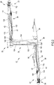
- FIG. 2 schematically shows some possible locations, in the crankset 12, of battery power supply units 100, 102, 104 and recharging ports 106, 108, 110, 112 for the aforementioned battery power supply units 100, 102, 104.
- battery power supply units 100, 102, 104 there are preferably up to three battery power supply units 100, 102, 104, and one or two recharging ports 106, 108, 110, 112 on one or both of the crankarms 22, 23.
- the electrical/electronic system supplied by the battery power supply unit(s) 100, 102, 104 is not shown specifically, since it could, as stated, be an electrical/electronic system of any type and having any purpose, or even plural electrical/electronic systems, the electrical/electronic components of which can be housed in a crankarm 22, 23, or distributed (also) on other components of the crankset or more in general of the transmission.
- the battery power supply unit 100 is associated with, preferably attached to, or even more preferably inserted in an inner cavity of, the crankarm 22 on the chain side.
- the battery power supply unit 102 is associated with, preferably attached to, or even more preferably inserted in an inner cavity of, the crankarm 23 on the side opposite to the chain side.
- the battery power supply unit 104 is associated with, preferably attached to, or even more preferably inserted in an inner cavity of, the bottom bracket spindle 26.
- the recharging ports 106, 108 and 110, 112 are made at a face of the main body 38, 39 of each crankarm 22, 23. More in particular, the recharging ports 106 and 110 are made at the proximal face 40, 41 of the respective crankarm 22, 23, while the recharging ports 108 and 112 are made at the distal face 42, 43 of the respective crankarm 22, 23. In a practical embodiment, there will typically be at most a single recharging port for each crankarm 22, 23. Preferably, there will be at most both of the recharging ports 106, 110 on the proximal side, and reference will only be made to these in the rest of the description for the sake of brevity.
- the battery power supply unit 100 if provided for, is rechargeable in a preferred manner through the recharging port 106, through a preferred path of recharging cables 118. Alternatively, the battery power supply unit 100 can also be charged through the recharging port 110 through the path of recharging cables 120.
- the battery power supply unit 102 if provided for, is rechargeable in a preferred manner through the recharging port 110, through the preferred path of recharging cables 124, but it can also be recharged through the recharging port 106 through the path of recharging cables 126.
- the battery power supply unit 104 can be recharged through the recharging port 106 through the path of recharging cables 132 or through the recharging port 110 through the path of recharging cables 134.
- the recharging cables 120, 126, 132, if provided for, pass through coaxial holes 136, 138 made between the crankarm 22 on the chain side and the bottom bracket spindle 26.
- the recharging cables 120, 126, 134, if provided for, pass through coaxial holes 140, 142 made between the crankarm 23 on the side opposite to the chain side and the bottom bracket spindle 26.
- each battery power supply unit 100, 102, 104 may have a single recharging cable 118, 120; 124, 126; 132, 134 extending therefrom, directed to a single respective one among the recharging ports 106, 110.
- Each battery power supply unit 100, 102, 104, if provided for, can however also be connected to both recharging ports 106, 110.
- each recharging port 106, 110 may have a single recharging cable 118, 126, 132; 120, 124, 134 extending therefrom, directed to a single respective one of the battery power supply units 100, 102, 104.
- Each recharging port 106, 110 can however also be connected to more than one battery power supply unit 100, 102, 104.
- the electrical/electronic components of the system supplied by a battery power supply unit 100, 102, 104 are coupled with, preferably attached to, and more preferably housed in, the same component of the respective battery power supply unit 100, 102, 104.
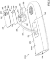
- FIGs. 3 and 4 illustrate a preferred embodiment of a battery power supply unit 200 with related recharging port 202, both supported by a crankarm 22, 23, shown in part.
- the battery power supply unit 200 thus represents one of the battery power supply units 100 and 102 of FIG. 2
- the recharging port 202 represents one of the recharging ports 106 and 110 (or 108, 112) of FIG. 2 .
- the crankarm 22, 23 comprises a cavity 204 extending for a certain length of its main body 38, 39.
- a hollow crankarm like the one shown is manufactured, in a composite material comprising structural fiber, for example through the process described in document EP1818252A1 , herein incorporated by reference.
- the cavity 204 houses electrical/electronic components 206 part of an electronic system, implementing for example a power meter as stated above.
- a first printed circuit board 208 or PCB sensors 210, specifically of the strain gage type or temperature sensors, and flexible circuits 212 for connection between the PCB 208 and the sensors 210.
- MCU Micro Controller Unit
- the battery power supply unit 200 is inserted in the cavity 204 of the crankarm 22, 23 at the end of manufacturing, through a suitable hole 214, made on the proximal face 216 of the crankarm, 22, 23.
- the battery power supply unit 200 can be fixed on an outer surface, in particular again at the proximal face 216, of the crankarm 22, 23.
- the battery power supply unit 200 comprises a button cell 217 of the rechargeable type, or two cells connected in series.
- the battery power supply unit 200 shown is of the smart type.
- the positive and negative poles of the cell 217 are connected to respective contacts 218 of a second printed circuit board 220 through respective cables 222.
- the second printed circuit board 220 is connected to the first printed circuit board 208 through a flexible circuit 224.
- the cables 222, the flexible circuit 224 and the second printed circuit board 220 are also inserted in the cavity 204.
- the second printed circuit board 220 carries a circuit intended for the management of the battery power supply unit 200, comprising in a per se known manner for example a voltage regulator, a protection circuit to avoid over/under-currents, -voltages or -temperatures at the cell 217, optionally a Coulomb counter to take the residual charge of the cell 217 into account.
- a third printed circuit board 226 carries a charge circuit that receives a charge voltage from mains or from a source external to the supplied electronic component.
- the second printed circuit board 220 or the third printed circuit board 226 could be absent.
- the third printed circuit board 226 is connected to the first printed circuit board 208 through a cable 228.
- the third printed circuit board 226 carries contacts 230, 231 on a face 232 thereof facing the hole 214 of the crankarm 22, 23.
- a cover 234 carries two contacts 236, 237 that match with the contacts 230, 231, respectively, to form the recharging port 202.
- a recharging device (not shown) comprises a second recharging port comprising two matched contacts, in turn supplied by an external source.
- the external source can be the mains, in which case the recharging device comprises a plug, or a hardware component, in which case the recharging device comprises a suitable connector, in particular a USB or miniUSB connector.
- the contacts 236, 237 of the recharging port 202 are of the flush type and there is at least one magnet, preferably a pair of magnets 238, 239 as shown, at the recharging port 202 for magnetic matching with a corresponding magnet(s) or metallic element(s) of the second recharging port of the recharging device.
- Holes 240, 241 can be provided in the third printed circuit board 226 to receive the magnets 238, 239.
- the contacts 236, 237 of the recharging port 202 are reversible contacts, namely the recharging can take place irrespective of the orientation of the two contacts of the recharging port of the recharging device with respect to the two contacts 236, 237 of the recharging port 202.
- the cover 234 closes the cavity 204 hermetically, in a tight manner.
- the cover 234 is glued or possibly welded along its edge to plug the cavity 204, preferably being received in a recessed seat 240 at the hole 214, so as to be substantially flush with the rest of the outer surface of the crankarm 22, 23, in particular of the proximal face 216 of the main body 38, 39 of the crankarm 22, 23.
- the recharging port 202 is also substantially flush with the rest of the outer surface of the crankarm 22, 23.
- crankarm made of composite material the invention can also be applied to a crankarm made of metallic material.
- the distribution of the various component on plural printed circuit boards shown is not essential, it being possible to provide for a single printed circuit board or a number of printed circuit boards greater than three.
Applications Claiming Priority (1)
| Application Number | Priority Date | Filing Date | Title |
|---|---|---|---|
| IT201800005297A IT201800005297A1 (it) | 2018-05-11 | 2018-05-11 | Pedivella di bicicletta e relativa guarnitura |
Publications (1)
| Publication Number | Publication Date |
|---|---|
| EP3566938A1 true EP3566938A1 (fr) | 2019-11-13 |
Family
ID=62952363
Family Applications (1)
| Application Number | Title | Priority Date | Filing Date |
|---|---|---|---|
| EP19173645.3A Pending EP3566938A1 (fr) | 2018-05-11 | 2019-05-09 | Manivelle de bicyclette et pédalier correspondant |
Country Status (7)
| Country | Link |
|---|---|
| US (1) | US11377169B2 (fr) |
| EP (1) | EP3566938A1 (fr) |
| JP (1) | JP2019209963A (fr) |
| CN (1) | CN110466662B (fr) |
| CA (1) | CA3042521A1 (fr) |
| IT (1) | IT201800005297A1 (fr) |
| TW (1) | TWI804616B (fr) |
Families Citing this family (4)
| Publication number | Priority date | Publication date | Assignee | Title |
|---|---|---|---|---|
| CN111516785B (zh) * | 2020-05-18 | 2021-12-10 | 湖州忻宝自动化科技有限公司 | 一种共享单车用带有侧面警示机构的曲柄脚蹬机构 |
| KR20210149493A (ko) * | 2020-06-02 | 2021-12-09 | 삼성전자주식회사 | 복수의 인쇄 회로 기판을 포함하는 전자 장치 |
| CN113602410A (zh) * | 2021-07-20 | 2021-11-05 | 建德市五星车业有限公司 | 一种助力输出机构及其安装方法和电助力自行车 |
| CN114715323B (zh) * | 2022-03-11 | 2024-04-09 | 上海从十到佰科技有限公司 | 一种能测量发力方向和位置的自行车用曲柄功率计 |
Citations (7)
| Publication number | Priority date | Publication date | Assignee | Title |
|---|---|---|---|---|
| EP1818252A1 (fr) | 2006-02-14 | 2007-08-15 | CAMPAGNOLO S.r.l. | Pèdalier de bicyclette, produit intermédiaire et méthode pour fabriquer un tel pèdalier |
| US20080236293A1 (en) * | 2007-04-02 | 2008-10-02 | Campagnolo S.R.L. | Instrument-equipped bicycle component and detection unit for equipping such a component |
| WO2011030215A1 (fr) * | 2009-09-14 | 2011-03-17 | Studio A.I.P. S.R.L. | Dispositif de détection de paramètres indicatifs d'activité physique, et vélo comprenant ce dispositif |
| US20120214646A1 (en) * | 2011-01-21 | 2012-08-23 | Foundation Fitness, LLC | Apparatus, system and method for power measurement |
| US20160052583A1 (en) * | 2014-08-22 | 2016-02-25 | Shimano Inc. | Bicycle pedal |
| WO2016030859A1 (fr) * | 2014-08-29 | 2016-03-03 | Roberts-Baxter Gregory John | Dispositif de mesure |
| US20170247078A1 (en) | 2015-05-27 | 2017-08-31 | Shimano Inc. | Bicycle electrical unit for bicycle crank assembly |
Family Cites Families (83)
| Publication number | Priority date | Publication date | Assignee | Title |
|---|---|---|---|---|
| FR2643712B1 (fr) | 1989-02-28 | 1991-06-07 | Look Sa | Procede de mesure du couple transmis a la roue motrice d'un cycle ou vehicule similaire et dispositif pour la mise en oeuvre de ce procede |
| US5027303A (en) | 1989-07-17 | 1991-06-25 | Witte Don C | Measuring apparatus for pedal-crank assembly |
| US5319522A (en) | 1992-12-17 | 1994-06-07 | Ford Motor Company | Encapsulated product and method of manufacture |
| FR2724728B1 (fr) | 1994-09-19 | 1999-12-24 | Wolfgang Petzke | Dispositif pour l'enregistrement et la mesure des caracteristiques de la force de pedalage fournie par un cycliste |
| US6296072B1 (en) * | 1999-01-20 | 2001-10-02 | Opti-Bike Llc | Electric bicycle and methods |
| US6549821B1 (en) | 1999-02-26 | 2003-04-15 | Micron Technology, Inc. | Stereolithographic method and apparatus for packaging electronic components and resulting structures |
| JP2000294692A (ja) | 1999-04-06 | 2000-10-20 | Hitachi Ltd | 樹脂封止型電子装置及びその製造方法並びにそれを使用した内燃機関用点火コイル装置 |
| GB2369889B (en) | 2001-07-13 | 2004-06-09 | John David Barnett | Strain sensing installation |
| AU2002330033A1 (en) | 2001-09-17 | 2003-04-01 | Compositech, Inc. | High performance bicycle crank |
| JP3896285B2 (ja) | 2002-01-24 | 2007-03-22 | 三菱電機株式会社 | 半導体装置の製造方法 |
| EP2110302A1 (fr) | 2003-06-11 | 2009-10-21 | CAMPAGNOLO S.r.l. | Composant de bicyclette |
| DE602004010780T2 (de) | 2004-03-05 | 2008-12-04 | Campagnolo S.R.L. | Einsatz für Fahrradtretkurbel |
| EP1818251A1 (fr) | 2006-02-14 | 2007-08-15 | CAMPAGNOLO S.r.l. | Pédalier de bicyclette, produit intermédiaire et méthode pour fabriquer un tel pédalier |
| DE102007005894A1 (de) | 2006-06-14 | 2007-12-20 | GIF Gesellschaft für Industrieforschung mbH | Drehmomentmessflansch |
| WO2008058164A2 (fr) | 2006-11-06 | 2008-05-15 | Quarq Technology, Inc. | Mesure de puissance de vélo à partir du pédalier |
| CN100533087C (zh) | 2006-12-14 | 2009-08-26 | 昆山双桥传感器测控技术有限公司 | 高精度压力传感器的误差补偿方法 |
| DE102007018928A1 (de) | 2007-04-21 | 2008-10-23 | Schaeffler Kg | Kompensationsvorrichtung |
| EP2141472A4 (fr) | 2007-04-25 | 2013-08-14 | Toyota Motor Co Ltd | Dispositif de détection de force d'action de pneu |
| ITMI20071221A1 (it) | 2007-06-19 | 2008-12-20 | Campagnolo Srl | Assieme di pedivella e relativi pedivella ed elemento per la trasmissione di coppia dalla pedivella ad una catena di bicicletta |
| WO2009006673A1 (fr) | 2007-07-06 | 2009-01-15 | Mark Fisher | Manivelle avec amplificateur d'effort |
| US7647837B2 (en) | 2007-08-29 | 2010-01-19 | Honeywell International Inc. | Active temperature differential compensation for strain gage based sensors |
| US8006574B2 (en) | 2007-11-06 | 2011-08-30 | Sram, Llc | Crankset based bicycle power measurement |
| US7806006B2 (en) | 2007-11-08 | 2010-10-05 | Grand Valley State University | Bicycle torque measuring system |
| JP5327052B2 (ja) | 2008-03-26 | 2013-10-30 | 住友電気工業株式会社 | 光電変換モジュールおよびそれを用いた光電対応情報処理機器 |
| CN201201674Y (zh) | 2008-04-01 | 2009-03-04 | 铨阳能源科技股份有限公司 | 电动自行车的扭力侦测器 |
| DE202009001463U1 (de) | 2009-02-06 | 2009-04-30 | Momes Llp | Vorrichtung zur Messung und Ermittlung der Kraft, der Momente und der Leistung an einer (Tret-)Kurbel |
| JP5146382B2 (ja) | 2009-03-25 | 2013-02-20 | 株式会社デンソー | 電子装置の製造方法 |
| WO2010148472A1 (fr) | 2009-06-23 | 2010-12-29 | Odomotion Inc. | Moteur électrique sans balai à flux axial |
| US20120150377A1 (en) * | 2009-08-20 | 2012-06-14 | James Buchhem | Electric motorized bicycle components and a wireless control system including such |
| WO2011063468A1 (fr) | 2009-11-28 | 2011-06-03 | Entecho Pty Ltd | Procédé avec système de manivelle cyclique et dispositifs associés |
| US8529476B2 (en) | 2009-12-28 | 2013-09-10 | Biosense Webster (Israel), Ltd. | Catheter with strain gauge sensor |
| US9476294B2 (en) | 2010-01-29 | 2016-10-25 | Baker Hughes Incorporated | Device and method for discrete distributed optical fiber pressure sensing |
| US20110135474A1 (en) | 2010-04-29 | 2011-06-09 | Matthias Thulke | Method for temperature calibration of blade strain gauges and wind turbine rotor blade containing strain gauges |
| CN201707167U (zh) | 2010-05-18 | 2011-01-12 | 北京遥测技术研究所 | 一种超低温薄膜压力温度复合传感器 |
| US9010201B2 (en) | 2010-10-22 | 2015-04-21 | Pioneer Corporation | Measurement apparatus and method |
| WO2012111007A1 (fr) | 2011-02-19 | 2012-08-23 | Watteam Ltd | Dispositif, procédé et système de fixation additive d'un capteur de déformation pour force appliquée sur un équipement d'exercice |
| ES2749600T3 (es) | 2011-07-18 | 2020-03-23 | Grassi Michael J | Sensor de par de torsión |
| DE202012012932U1 (de) | 2011-08-02 | 2014-04-08 | Rotor Componentes Technologicos S.L. | Tret-Drehmomentsensorvorrichtung für jedes Bein des Fahrradfahrers und Leistungsmessgerät |
| GB2493556A (en) | 2011-08-12 | 2013-02-13 | Bf1 Systems Ltd | Cycle cranks with torque and angular position measurement |
| JP5719936B2 (ja) | 2011-09-30 | 2015-05-20 | パイオニア株式会社 | パワーメータ、仕事率測定方法、プログラム及び記録媒体 |
| US9254588B1 (en) | 2011-11-28 | 2016-02-09 | The United States Of America As Represented By The Secretary Of The Army | Protective layering process for circuit boards |
| US8800389B2 (en) | 2012-03-07 | 2014-08-12 | Shimano, Inc. | Bicycle crank arm with an input force processing apparatus |
| US8881608B2 (en) | 2012-03-07 | 2014-11-11 | Shimano Inc. | Bicycle crank arm |
| CN102589772B (zh) | 2012-03-21 | 2013-12-18 | 株洲易力达机电有限公司 | 一种新型的电动助力转向系统扭矩传感器 |
| EP2805141B1 (fr) | 2012-04-09 | 2018-06-06 | Belon Engineering Inc. | Capteur de rotation pour pédale de bicyclette électrique |
| US8689645B2 (en) | 2012-04-25 | 2014-04-08 | Shimano Inc. | Bicycle crank arm |
| FR2993202B1 (fr) | 2012-07-13 | 2014-08-22 | Roxel France | Nouveaux materiaux composites alleges, leurs procedes de fabrication et leurs utilisations. |
| JP5918657B2 (ja) | 2012-08-28 | 2016-05-18 | 株式会社シマノ | 踏力計測装置 |
| CN102798448B (zh) | 2012-09-06 | 2015-02-04 | 上海新世纪机器人有限公司 | 自平衡两轮车负载在线检测装置 |
| DE102012022447A1 (de) | 2012-11-16 | 2014-05-22 | Storck Bicycle Gmbh | Kurbelarm, Kurbelgarnitur und Leistungsmesseinrichtung für ein zumindest teilweise muskelgetriebenes Fahrzeug oder Trainingsgerät mit Kurbelantrieb |
| FR3001290B1 (fr) | 2013-01-18 | 2015-03-27 | Mavic Sas | Moyeu de mesure de couple, systeme de mesure de puissance, roue de cycle equipee d'un tel moyeu ou d'un tel systeme et methode de mesure au moyen d'un tel moyeu |
| US20160003696A1 (en) * | 2013-02-22 | 2016-01-07 | Breakaway Innovations Pty Ltd | Crank Arm Electronics Packaging |
| US10259160B2 (en) | 2013-03-22 | 2019-04-16 | Markforged, Inc. | Wear resistance in 3D printing of composites |
| CN103612702B (zh) | 2013-10-29 | 2016-06-29 | 苏州莱士格车业有限公司 | 电动自行车中的调速装置 |
| US9221440B2 (en) | 2013-11-07 | 2015-12-29 | Goodrich Corporation | Electromechanical actuator strain gauge temperature compensation device |
| WO2015095933A1 (fr) | 2013-12-27 | 2015-07-02 | Breakaway Innovations Pty Ltd | Améliorations apportées à la collecte de données du système de manivelle |
| US9423310B2 (en) | 2014-02-28 | 2016-08-23 | Shimano Inc. | Bicycle crank arm with sensor system |
| US9580138B2 (en) | 2014-07-30 | 2017-02-28 | Shimano Inc. | Bicycle crank assembly |
| US9969451B2 (en) | 2014-08-22 | 2018-05-15 | Shimano Inc. | Bicycle pedal |
| WO2016030768A2 (fr) | 2014-08-26 | 2016-03-03 | 4Iiii Innovations Inc. | Appareil de mesure de puissance couplé de manière adhésive pour la mesure de force, de couple et de puissance, et procédés associés |
| ES2535582B1 (es) | 2015-01-19 | 2016-01-25 | Rotor Componentes Tecnológicos S.L. | Dispositivo de medición del par y la potencia de pedaleo en una bicicleta |
| US9581508B2 (en) | 2015-01-23 | 2017-02-28 | Shimano Inc. | Bicycle pedaling force detector |
| US9829402B2 (en) | 2015-02-03 | 2017-11-28 | Goodrich Corporation | Actuator system with smart load cell |
| CN204527067U (zh) | 2015-03-20 | 2015-08-05 | 山东省科学院自动化研究所 | 一种低功耗车身控制器 |
| US10091887B2 (en) | 2015-04-02 | 2018-10-02 | Tactotek Oy | Multi-material structure with embedded electronics |
| US9919616B2 (en) | 2015-04-21 | 2018-03-20 | Shimano Inc. | Control system for bicycle |
| US10141268B2 (en) | 2015-10-30 | 2018-11-27 | Avago Technologies International Sales Pte. Limited | Circuit package with internal and external shielding |
| CN205156906U (zh) | 2015-11-23 | 2016-04-13 | 东北石油大学 | 一种混凝土应变计 |
| JP6460972B2 (ja) | 2015-12-21 | 2019-01-30 | 株式会社シマノ | クランクアームアッセンブリ |
| CN205352592U (zh) * | 2016-02-01 | 2016-06-29 | 李运隆 | 一种安装于自行车中轴及曲柄上的功率计 |
| US11033217B2 (en) | 2016-03-21 | 2021-06-15 | 4Iiii Innovations Inc. | Crank measurement system with improved strain gauge installation |
| DE102016105219A1 (de) | 2016-03-21 | 2017-09-21 | Infineon Technologies Dresden Gmbh | Halbleiterbatterie und Halbleitervorrichtung, die eine Halbleiterbatterie enthält |
| US9784628B1 (en) | 2016-04-12 | 2017-10-10 | Sram, Llc | Bicycle power meter |
| US10184849B2 (en) | 2016-04-12 | 2019-01-22 | Sram, Llc | Bicycle power meter |
| CN106003753B (zh) | 2016-05-12 | 2018-08-28 | 北京鸿鹄雄狮技术开发有限公司 | 一种制备复杂内腔制件的方法 |
| US10591371B2 (en) | 2016-06-10 | 2020-03-17 | Level Engineering, Inc. | Systems and methods for measuring drivetrain power transmission |
| US10416186B2 (en) | 2016-07-06 | 2019-09-17 | Sram, Llc | Pedal activity sensor and methods of pedaling analysis |
| CN205971719U (zh) * | 2016-07-26 | 2017-02-22 | 黄继乐 | 一种自行车的力矩检测装置 |
| CN106335591B (zh) | 2016-08-31 | 2019-01-25 | 太仓市悦博电动科技有限公司 | 用于自行车或辅助动力自行车的直贴式功率计及安装方法 |
| US10000253B1 (en) | 2016-11-25 | 2018-06-19 | Shimano Inc. | Bicycle crank assembly |
| IT201700038213A1 (it) | 2017-04-06 | 2018-10-06 | Campagnolo Srl | Dispositivo manuale di comando per bicicletta e sistema elettronico di bicicletta che lo comprende |
| CN207019821U (zh) | 2017-06-24 | 2018-02-16 | 深圳市科尚通信有限公司 | 一种基于力和速度测试的曲柄功率计系统 |
| US10286978B1 (en) | 2018-04-18 | 2019-05-14 | TWDT Precision Co., Ltd. | Bicycle crank arm with strain gauge |
-
2018
- 2018-05-11 IT IT201800005297A patent/IT201800005297A1/it unknown
-
2019
- 2019-05-06 CA CA3042521A patent/CA3042521A1/fr active Pending
- 2019-05-06 TW TW108115485A patent/TWI804616B/zh active
- 2019-05-09 EP EP19173645.3A patent/EP3566938A1/fr active Pending
- 2019-05-09 US US16/407,607 patent/US11377169B2/en active Active
- 2019-05-09 JP JP2019089044A patent/JP2019209963A/ja active Pending
- 2019-05-10 CN CN201910388125.9A patent/CN110466662B/zh active Active
Patent Citations (8)
| Publication number | Priority date | Publication date | Assignee | Title |
|---|---|---|---|---|
| EP1818252A1 (fr) | 2006-02-14 | 2007-08-15 | CAMPAGNOLO S.r.l. | Pèdalier de bicyclette, produit intermédiaire et méthode pour fabriquer un tel pèdalier |
| US20080236293A1 (en) * | 2007-04-02 | 2008-10-02 | Campagnolo S.R.L. | Instrument-equipped bicycle component and detection unit for equipping such a component |
| EP1978342A2 (fr) | 2007-04-02 | 2008-10-08 | CAMPAGNOLO S.r.l. | Composant de bicyclette équipé d'un instrument et unité de détection pour équiper un tel composant |
| WO2011030215A1 (fr) * | 2009-09-14 | 2011-03-17 | Studio A.I.P. S.R.L. | Dispositif de détection de paramètres indicatifs d'activité physique, et vélo comprenant ce dispositif |
| US20120214646A1 (en) * | 2011-01-21 | 2012-08-23 | Foundation Fitness, LLC | Apparatus, system and method for power measurement |
| US20160052583A1 (en) * | 2014-08-22 | 2016-02-25 | Shimano Inc. | Bicycle pedal |
| WO2016030859A1 (fr) * | 2014-08-29 | 2016-03-03 | Roberts-Baxter Gregory John | Dispositif de mesure |
| US20170247078A1 (en) | 2015-05-27 | 2017-08-31 | Shimano Inc. | Bicycle electrical unit for bicycle crank assembly |
Non-Patent Citations (1)
| Title |
|---|
| RON: "Electric bicycles are adopting a new standard for connectors | ELECTRICBIKE.COM", 6 December 2013 (2013-12-06), XP055559683, Retrieved from the Internet <URL:https://www.electricbike.com/ropdenergybus-charging-port-standard/> [retrieved on 20190220] * |
Also Published As
| Publication number | Publication date |
|---|---|
| CA3042521A1 (fr) | 2019-11-11 |
| TW201946826A (zh) | 2019-12-16 |
| IT201800005297A1 (it) | 2019-11-11 |
| JP2019209963A (ja) | 2019-12-12 |
| US20190344858A1 (en) | 2019-11-14 |
| CN110466662B (zh) | 2023-02-17 |
| US11377169B2 (en) | 2022-07-05 |
| CN110466662A (zh) | 2019-11-19 |
| TWI804616B (zh) | 2023-06-11 |
Similar Documents
| Publication | Publication Date | Title |
|---|---|---|
| US11377169B2 (en) | Bicycle crankarm and related crankset | |
| US9902253B2 (en) | Yoke module system for powering a motorized wheel | |
| US10220913B2 (en) | Bicycle chain tensioner device | |
| CN107364536B (zh) | 自行车曲柄组件 | |
| EP2534034B1 (fr) | Mise en place d'une alimentation électrique sur une bicyclette à moteur électrique | |
| US9428246B2 (en) | Bicycle generator and/or shifting device | |
| TW201627200A (zh) | 自行車踩踏力偵測器 | |
| US9097598B2 (en) | Torque sensor | |
| EP3088289B1 (fr) | Système de commande monté au centre d'une bicyclette | |
| TW201533434A (zh) | 曲柄臂 | |
| TW201336738A (zh) | 自行車曲柄臂 | |
| US20230015750A1 (en) | Power transmission unit for electric bicycles, and electric bicycle | |
| JP2012187963A (ja) | トルク検出装置、トルク検出装置ユニット、及び電動アシスト自転車 | |
| US20220258531A1 (en) | Wheel Hub, Auxiliary Driven Vehicle with the Wheel Hub and Clip Arrangement | |
| WO2022034497A1 (fr) | Pédale pour bicyclettes à générateur intégré | |
| US20230365226A1 (en) | Articulated parallelogram bicycle electric/electronic derailleur | |
| US20210175760A1 (en) | Sensing device | |
| TWM553291U (zh) | 自行車用變速單元 | |
| CN213354753U (zh) | 电子后拨链器 | |
| US20210239551A1 (en) | Sensing device | |
| CA2925042C (fr) | Structure de pedale de bicyclette capable de declencher une alimentation auxiliaire | |
| EP3480104A1 (fr) | Moteur d'entraînement à manivelle pour bicyclette électrique avec changement de vitesse automatique |
Legal Events
| Date | Code | Title | Description |
|---|---|---|---|
| PUAI | Public reference made under article 153(3) epc to a published international application that has entered the european phase |
Free format text: ORIGINAL CODE: 0009012 |
|
| STAA | Information on the status of an ep patent application or granted ep patent |
Free format text: STATUS: THE APPLICATION HAS BEEN PUBLISHED |
|
| AK | Designated contracting states |
Kind code of ref document: A1 Designated state(s): AL AT BE BG CH CY CZ DE DK EE ES FI FR GB GR HR HU IE IS IT LI LT LU LV MC MK MT NL NO PL PT RO RS SE SI SK SM TR |
|
| AX | Request for extension of the european patent |
Extension state: BA ME |
|
| STAA | Information on the status of an ep patent application or granted ep patent |
Free format text: STATUS: REQUEST FOR EXAMINATION WAS MADE |
|
| 17P | Request for examination filed |
Effective date: 20200508 |
|
| RBV | Designated contracting states (corrected) |
Designated state(s): AL AT BE BG CH CY CZ DE DK EE ES FI FR GB GR HR HU IE IS IT LI LT LU LV MC MK MT NL NO PL PT RO RS SE SI SK SM TR |
|
| STAA | Information on the status of an ep patent application or granted ep patent |
Free format text: STATUS: EXAMINATION IS IN PROGRESS |
|
| STAA | Information on the status of an ep patent application or granted ep patent |
Free format text: STATUS: EXAMINATION IS IN PROGRESS |
|
| 17Q | First examination report despatched |
Effective date: 20210120 |
|
| P01 | Opt-out of the competence of the unified patent court (upc) registered |
Effective date: 20230516 |