EP3566596A2 - Abnehmbarer aerosolerzeugender artikel - Google Patents
Abnehmbarer aerosolerzeugender artikel Download PDFInfo
- Publication number
- EP3566596A2 EP3566596A2 EP19187852.9A EP19187852A EP3566596A2 EP 3566596 A2 EP3566596 A2 EP 3566596A2 EP 19187852 A EP19187852 A EP 19187852A EP 3566596 A2 EP3566596 A2 EP 3566596A2
- Authority
- EP
- European Patent Office
- Prior art keywords
- tube
- atomizer
- generating article
- base
- liquid conductive
- Prior art date
- Legal status (The legal status is an assumption and is not a legal conclusion. Google has not performed a legal analysis and makes no representation as to the accuracy of the status listed.)
- Granted
Links
Images


Classifications
-
- A—HUMAN NECESSITIES
- A24—TOBACCO; CIGARS; CIGARETTES; SIMULATED SMOKING DEVICES; SMOKERS' REQUISITES
- A24F—SMOKERS' REQUISITES; MATCH BOXES; SIMULATED SMOKING DEVICES
- A24F40/00—Electrically operated smoking devices; Component parts thereof; Manufacture thereof; Maintenance or testing thereof; Charging means specially adapted therefor
- A24F40/40—Constructional details, e.g. connection of cartridges and battery parts
- A24F40/42—Cartridges or containers for inhalable precursors
-
- A—HUMAN NECESSITIES
- A24—TOBACCO; CIGARS; CIGARETTES; SIMULATED SMOKING DEVICES; SMOKERS' REQUISITES
- A24F—SMOKERS' REQUISITES; MATCH BOXES; SIMULATED SMOKING DEVICES
- A24F40/00—Electrically operated smoking devices; Component parts thereof; Manufacture thereof; Maintenance or testing thereof; Charging means specially adapted therefor
- A24F40/40—Constructional details, e.g. connection of cartridges and battery parts
- A24F40/46—Shape or structure of electric heating means
-
- A—HUMAN NECESSITIES
- A24—TOBACCO; CIGARS; CIGARETTES; SIMULATED SMOKING DEVICES; SMOKERS' REQUISITES
- A24F—SMOKERS' REQUISITES; MATCH BOXES; SIMULATED SMOKING DEVICES
- A24F40/00—Electrically operated smoking devices; Component parts thereof; Manufacture thereof; Maintenance or testing thereof; Charging means specially adapted therefor
- A24F40/40—Constructional details, e.g. connection of cartridges and battery parts
- A24F40/48—Fluid transfer means, e.g. pumps
- A24F40/485—Valves; Apertures
-
- H—ELECTRICITY
- H05—ELECTRIC TECHNIQUES NOT OTHERWISE PROVIDED FOR
- H05B—ELECTRIC HEATING; ELECTRIC LIGHT SOURCES NOT OTHERWISE PROVIDED FOR; CIRCUIT ARRANGEMENTS FOR ELECTRIC LIGHT SOURCES, IN GENERAL
- H05B3/00—Ohmic-resistance heating
- H05B3/02—Details
- H05B3/03—Electrodes
-
- H—ELECTRICITY
- H05—ELECTRIC TECHNIQUES NOT OTHERWISE PROVIDED FOR
- H05B—ELECTRIC HEATING; ELECTRIC LIGHT SOURCES NOT OTHERWISE PROVIDED FOR; CIRCUIT ARRANGEMENTS FOR ELECTRIC LIGHT SOURCES, IN GENERAL
- H05B3/00—Ohmic-resistance heating
- H05B3/02—Details
- H05B3/06—Heater elements structurally combined with coupling elements or holders
-
- A—HUMAN NECESSITIES
- A24—TOBACCO; CIGARS; CIGARETTES; SIMULATED SMOKING DEVICES; SMOKERS' REQUISITES
- A24F—SMOKERS' REQUISITES; MATCH BOXES; SIMULATED SMOKING DEVICES
- A24F40/00—Electrically operated smoking devices; Component parts thereof; Manufacture thereof; Maintenance or testing thereof; Charging means specially adapted therefor
- A24F40/10—Devices using liquid inhalable precursors
-
- H—ELECTRICITY
- H05—ELECTRIC TECHNIQUES NOT OTHERWISE PROVIDED FOR
- H05B—ELECTRIC HEATING; ELECTRIC LIGHT SOURCES NOT OTHERWISE PROVIDED FOR; CIRCUIT ARRANGEMENTS FOR ELECTRIC LIGHT SOURCES, IN GENERAL
- H05B2203/00—Aspects relating to Ohmic resistive heating covered by group H05B3/00
- H05B2203/021—Heaters specially adapted for heating liquids
Definitions
- the present disclosure relates to the field of heated aerosol-generating articles, and particularly to a detachable aerosol-generating article.
- a heated aerosol-generating article as an electronically-operated product mimicking traditional cigarettes has advantages of safety, convenience, healthy and environmental friendly, which is widely applied to our daily life.
- a disposable aerosol-generating article typically integrates a cartridge and a atomizer.
- a liquid aerosolizable material i.e. tobacco liquid
- the cartridge and the atomizer would be discarded together.
- the inventors found that the atomizer can be reused after the liquid aerosolizable material is used out, while discarding the cartridge and the atomizer both causes cost-wasting over time.
- the present disclosure generally relates to a detachable aerosol-generating article which may resolve a technical problem that the cartridge and the atomizer have to be discarded together in the prior art.
- the article includes: a cartridge, with a reservoir and a path formed therein; the path formed inside the reservoir and an atomizer, disposed inside the path and detachably connected with the cartridge; the cartridge further comprises a first tube and a second tube; the second tube is sleeved on the first tube; the first tube and the second tube are relatively rotatable to each other; and the path is formed inside the first tube; the first tube is bored with a first liquid conductive hole; the second tube is bored with a second liquid conductive hole; when the cartridge and the atomizer are assembled, the first liquid conductive hole is aligned with the second liquid conductive hole, thus allowing tobacco liquid in the reservoir to flow to the atomizer; when the cartridge and the atomizer are detached, the first liquid conductive hole and the second liquid conductive hole are misaligne
- the detachable aerosol-generating article further includes a mouthpiece at a mouth end of the detachable aerosol-generating article and a distal end of the detachable aerosol-generating article upstream from the mouth end; upstream of the mouth piece has a shaft with protrusions; the atomizer has a connector; the connector is detachably connected with the shaft in the path such that when the mouthpiece is detached from the atomizer, the cartridge is detached from the atomizer.
- the shaft includes a first protrusion, downstream of the connector has a clamping portion, the first protrusion is clamped by the clamping portion.
- the shaft includes a second protrusion, downstream of the first tube has a groove, the second protrusion is received in the groove such that the first tube rotates with the mouthpiece.
- the cartridge includes a first shell and a base; the base is disposed upstream of the first shell; the first tube is carried on the first shell and extends to the base; the first tube, the first shell and the base encompass a reservoir.
- the atomizer includes an atomizing assembly disposed inside the path; the atomizing assembly includes a heater and a liquid conductive element, the liquid conductive element is sleeved on the heater; an air flow path is formed inside the heater.
- the base includes a first base and a second base; the second base is upstream of the first base; an downstream side of the second base is bored with an aeration slot for forming an air inlet path when the first base is engaged with the second base; the air inlet path is in communication with the air flow path.
- the atomizer further includes a supporter, the supporter having a receivable part; the receivable part and the connector are abutting each other and both are sleeved on the liquid conductive element; the receivable part is bored with a third liquid conductive hole; the third liquid conductive hole is aligned with the second liquid conductive hole.
- the supporter includes a connecting part;
- the atomizer includes a third tube and a basal plug; the basal plug is secured with the connecting part; the third tube is sleeved on the connector, the supporter and the basal plug such that the connector, the supporter and the basal plug are secured.
- the article further includes a power supply device; the power supply device includes a power supply set; the power supply set is disposed inside the power supply device; the heater further includes an electrode mast, the electrode mast successively passes through the connecting part and the basal plug to electrically connect power supply set for supplying power to the heater to atomize the tobacco liquid.
- the atomizer is disposed inside the path that is formed inside the first tube; the first tube and the second tube are relatively rotatable to each other; when the cartridge and the atomizer are assembled, the first liquid conductive hole and the second liquid conductive hole are aligned with each other; when the cartridge and the atomizer are detached, the first liquid conductive hole and the second liquid conductive hole are misaligned to prevent the tobacco liquid from leaking out, which may effectively avoid environmental pollution without affecting the usage of the atomizer.
- an electronically-operated aerosol-generating article generally heats a liquid aerosolizable material (i.e. tobacco liquid) containing nicotine to generate an aerosol, eventually drawn by the users.
- a liquid aerosolizable material i.e. tobacco liquid
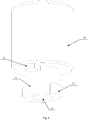
- the present disclosure relates to a detachable aerosol-generating article 100 that may be but not limited to a disposable aerosol-generating article 100.
- the aerosol-generating article 100 includes a mouthpiece 10, a cartridge 30, an atomizer 50 and a power supply device 70.
- the mouthpiece is at a mouth end of the detachable aerosol-generating article 100, and a distal end of the detachable aerosol-generating article 100 is upstream from the mouth end.
- Upstream of the mouthpiece has a shaft 11.
- the shaft 11 has a first protrusion 12 and a second protrusion 13 formed thereon.
- the first protrusion 12 is upstream of the shaft 11 while the second protrusion 13 is downstream of the first protrusion 12.
- the number of the first protrusions 12 and the second protrusions 13 is two, the first protrusions 12 and the second protrusions 13 are staggered along a circumferential direction of the shaft 11.
- the number of the first protrusions 12 and the second protrusions 13 are determined based on actual need, no further limitation herein.
- the aerosol outlet path 14 is extending through the mouthpiece 10.
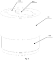
- the cartridge 30 includes a first shell 31, a base 32, a first tube 33, a second tube 34, a first sealing ring 35 and a second sealing ring 36.
- the base 32 is disposed upstream of the first shell 31; the first tube 33 is extending through the first shell 31 towards the base 32.
- the first tube 33, the first shell 31 and the base 32 encompass a reservoir 37.
- a first tube 33 has a path 330 formed therein.
- the first shell 31 includes a first sidewall 311 and a first top wall 312.
- the first top wall 312 has a sleeve 313 with a first through hole 314 bored thereon.
- the first through hole 314 may be a step hole.
- Each of two ends of the first tube 33 has a fixing part 331 and a folding part 332. Inside wall of the first through hole 314 protrudes a bump 315.
- the first tube 33 passes through the first through hole 314 so that the fixing part 331 abuts against the bump 315 inside the first through hole 314, in this case, the first tube 33 is secured on the first shell 31.
- the base 32 includes a first base 321 and a second base 323.
- the first base 321 is configured for sealing the reservoir 37.
- the second base 323 being upstream of the first base 321 is configured for securing the first base 321 with the first base 31.
- the first base 321 is bored with a second through hole 323; the second base 322 is bored with a third through hole 324.
- the first through hole 314, the second through hole 323 and the third through hole 324 are aligned to each other.
- upstream of the first base 321 has a fixing block 325, the folding part 332 of the first tube 33 abuts against the fixing block 325 with consequently securing he first tube 33.
- first sealing ring 35 is disposed between the fixing part 331 and the bump 315; the second sealing ring 36 is disposed between the folding part 332 and the first base 321 to avoid leakage of the tobacco liquid in the reservoir 37.
- the second tube 34 is sleeved on the first tube 33. An end of the second tube 34 is imbedded between the sleeve 313 and the first tube 33, an opposite end thereof is imbedded between the first base 321 and the folding part 332, therefore the second tube 34 is secured.
- the first tube 33 is bored with a first liquid conductive hole 333
- the second tube 34 is bored with a second liquid conductive hole 341.
- the first liquid conductive hole 333 is aligned with the second liquid conductive hole 341; when the cartridge 30 is disassembled with the atomizer 50, the first liquid conductive hole 333 is misaligned with the second liquid conductive hole 341 to avoid leakage of tobacco liquid.
- the atomizer 9 is disposed in the path 330, the atomizer 50 includes an atomizing assembly 51, a supporter 52, a connector 53, a third tube 54, a basal plug 55 and a retainer 56.
- the atomizing assembly 51 includes a liquid conductive element 511 and a heater 512, the liquid conductive element 511 is sleeved on the heater 512, inside of the heater 512 has an air flow path 513.
- the air flow path 513 is in communication with the aerosol outlet path 14, such that the atomizing assembly 51 absorbs the tobacco liquid in the reservoir 37 to heat, generating an aerosol drawn by the user through the aerosol outlet path 14.
- the supporter 52 is sleeved on the liquid conductive element 511, the supporter 52 includes a receivable part 521 and a connecting part 522.
- the receivable part 521 is imbedded in the path 330 for receiving the atomizing assembly 51.
- the receivable part 521 is hollow and the atomizing assembly 51 is disposed inside the receivable part 521.
- the receivable part 521 is bored with a third liquid conductive hole 523, the third liquid conductive hole 523 is aligned with the second liquid conductive hole 341.
- the tobacco liquid in the reservoir 37 flows through the second liquid conductive hole 341, the first liquid conductive hole 333 and the third liquid conductive hole 523 towards the liquid conductive element 511, further atomized by the heater 512 to form the aerosol.
- the connecting part 522 is disposed upstream of the atomizing assembly 51, secured with the basal plug 55. More specifically, the basal plug 55 has a first step hole 551.
- the connecting part 522 is bored with a connecting hole 524 that is aligned with the first step hole 551, enabling the retainer 56 to successively pass through the first step hole 551 and the connecting hole 524 so as to secure the supporter 52 with the basal plug 55.
- the retainer 52 is but not limited to a screw bolt.
- the basal plug 55 is disposed upstream of the air flow path 513, avoiding the tobacco liquid leaking out from the atomizing assembly 51.
- the connector 53 is disposed inside the path 330.
- the connector 53 and the supporter 52 are sleeved on the liquid conductive element 511.
- a clamping portion 531 is formed on inside wall of the connector 53 downstream of the supporter 52.
- the clamping portion 531 is connected with the first protrusion 12 via snap joint, thus the connector 53 is connected with the mouthpiece 10, in this case, the mouthpiece 10 is detachably connected with the atomizer 50.
- the shaft 11 has two first protrusions 12, accordingly, the inside wall of the connector 53 has two symmetrically-set clamping portions 531. Between the two clamping portions 531 there is a notch 532.
- the first protrusion 12 inserts into the notch 532, extending to the clamping portions 531, then the mouthpiece 10 is rotated to finish the assembling of the cartridge 30 and the atomizer 50.
- the mouthpiece 10 is rotated such that the first protrusions 12 are rotated to the notches 532, then removing the mouthpiece 10 from the connector 53.
- the above connection way has a simple structure and is easy to operate.
- the cartridge 30 is secured with the atomizer 50.
- the cartridge 30 is detached with the atomizer 50. If so, when the tobacco liquid in the cartridge 30 is used up, the cartridge 30 is replaced only but the atomizer 50 can be reused, which may avoid cost-wasting and improve competition of the products.
- the fixing part 331 of the first tube 33 is bored with a groove 334, the second protrusion 13 is received in the groove 334. In this case, the mouthpiece 10 is rotated to bring the first tube 33 to rotate.
- the first liquid conductive hole 333 is aligned with the second liquid conductive hole 341, the tobacco liquid flows respectively through the second liquid conductive hole 341, the first liquid conductive hole 333 to the liquid conductive element 511, eventually aerosolized.
- rotating the mouthpiece 10 causes the first tube 33 to rotate simultaneously, in this case, the first liquid conductive hole 333 and the second liquid conductive hole 341 are misaligned which may effectively avoid leakage of the tobacco liquid in the reservoir 37.
- an outer diameter of the first concave part 533 is equal to an outer diameter of the receivable part 521 and an outer diameter of the basal plug 55.
- the third tube 54 is sleeved on the first concave part 533 of the connector 53, the supporter 52 and the basal plug 55 so as to secure them.
- the supporter 52 protrudes towards the first tube 33 to form a casing wall 525 encircling the third liquid conductive hole 523.
- the third tube 54 is bored with a fixing hole 542 that is sleeved on the casing wall 525, therefore securing the third tube 54 on the supporter 52.
- the third tube 54 is bored with a round hole 543.
- An downstream side of the second base 322 is bored with an aeration slot 326 for forming an air inlet path when the first base is engaged with the second base; the round hole is in communication with the air inlet path, thus the air inlet path is in communication with the air flow path 513. Therefore, the air may flow through the air inlet path to the atomizing assembly 51.
- the third tube 54 is bored with four round holes 543.
- the number of round holes 543 is determined according to the actual need, which is not limited herein.
- the outer diameter of the connecting part 522 of the supporter 52 is less than the outer diameter of the receivable part 521, thus when the third tube 54 is sleeved on the supporter 52, a certain space is formed between an inside wall of the third tube 54 and an outside wall of the connecting part 522. Furthermore, the connecting part 522 of the supporter 52 is bored with an air conductive hole 525. And upstream of the connecting part 522 is bored with an air conductive slot 526. In this case, the external air may successively flow through the air inlet path, the round hole 543, the air conductive hole 525 to the airflow path 513.
- first tube 33, the second tube 34 and the third tube 54 are all made of stainless steel.
- the power supply device 70 includes a second case 71, a third case 72, an end case 73, a power supply set 74 and a carrier 75.
- the second case 71 includes a second side wall 711 and a second top wall 712.
- the second top wall 712 encompasses the second top wall 712.
- the end case 73 is sleeved on upstream of the second case 71 to form a cavity 713 with the second case 71.
- the cavity 713 is configured for receiving the power supply set 74.
- upstream of the second side wall 711 has a second concave part 714, the end case 73 is sleeved on the second concave part 714 to secure with each other.
- the second top wall 712 has a compartment 715 concaved thereon.
- the compartment 715 is configured for receiving the carrier 75.
- the carrier 75 abuts an inside wall of the compartment 715.
- the carrier 75 is hollow, the basal plug 55 is imbedded into the carrier 75.
- upstream of the basal plug 55 has a third protrusion 553, accordingly, upstream of the carrier 75 is bored with a clamping portion 751.
- the third protrusion 553 is connected with the clamping portion 751 via snap joint to avoid relatively sliding of the carrier 75 and the basal plug 55 and thus the carrier 75 is secured on the basal plug 55.
- two third protrusions 553 and two clamping portions 751 are provided herein.
- the clamping portions 751 and the clamping portions 531 have the same structure.
- the structure of the clamping portion 751 is the same as the structure of the groove 334, which is no more limitation herein.
- the heater 512 further includes an electrode mast 514, the retainer 56 is bored with a through hole 561, upstream of the compartment 715 is bored with a second step hole 713, allowing the electrode mast 514 to successively pass through the through hole 561 and the second step hole 713 to be electrically connected with the power supply set 74, therefore supplying power to the heater 512 for atomizing the tobacco liquid.
- the third case 72 is sleeved on at least part of the first case 31 and the second case 71 so as to secure the first case 31 and the second case 71.
- upstream of the first side wall 311 of the first case 31 is dented to form a third concave part 316
- downstream of the second side wall 711 of the second case 71 is dented to form a fourth concave part 716.
- the third case 72 is sleeved on the third concave part 316 and the fourth concave part 716, so the first case 31 is secured with the second case 71.
- downstream of the third case 72 is dented to form a recess 721, upstream of the first shell 31 protrudes to form a clamping block 315, the clamping block 315 is clamped in the recess 721 so as to secure the first case 31 on the third case 72.
- a seam 722 appears between a surface of the recess 721 and the clamping block 315, the seam 722 is in communication with the air flow path 513, allowing external air to flow smoothly into the air flow path.
- the connector 53 of the atomizer 50 is secured with the shaft 11 of the mouth piece 10 in the path 330 that is formed inside the cartridge 30, when the mouthpiece 10 is secured with the atomizer 50, the cartridge 30 is secured with the atomizer 50 too; when the mouthpiece 10 is removed from the atomizer 50, the cartridge 30 is detached from the atomizer 50, therefore, upon the tobacco liquid in the cartridge 30 is used up, only need to replace the cartridge 30 but the atomizer 50 can be reused, the electrically-operated aerosol generating article 100 may effectively avoid cost-wasting and make the products more competitive over time.
Landscapes
- Electrostatic Spraying Apparatus (AREA)
Applications Claiming Priority (2)
| Application Number | Priority Date | Filing Date | Title |
|---|---|---|---|
| CN201821169966.8U CN209251746U (zh) | 2018-07-23 | 2018-07-23 | 一种电子烟 |
| CN201810812863.7A CN108851243B (zh) | 2018-07-23 | 2018-07-23 | 一种分离式电子烟 |
Publications (3)
| Publication Number | Publication Date |
|---|---|
| EP3566596A2 true EP3566596A2 (de) | 2019-11-13 |
| EP3566596A3 EP3566596A3 (de) | 2020-01-22 |
| EP3566596B1 EP3566596B1 (de) | 2021-05-19 |
Family
ID=67438560
Family Applications (1)
| Application Number | Title | Priority Date | Filing Date |
|---|---|---|---|
| EP19187852.9A Active EP3566596B1 (de) | 2018-07-23 | 2019-07-23 | Abnehmbarer aerosolerzeugender artikel |
Country Status (2)
| Country | Link |
|---|---|
| US (1) | US12096792B2 (de) |
| EP (1) | EP3566596B1 (de) |
Cited By (2)
| Publication number | Priority date | Publication date | Assignee | Title |
|---|---|---|---|---|
| EP4008201A1 (de) * | 2020-12-01 | 2022-06-08 | JT International SA | Cartomizer mit drehenden teilen für ein aerosol-generationsgerät |
| EP4008202A1 (de) * | 2020-12-01 | 2022-06-08 | JT International SA | Cartomizer mit befestigungselementen für ein aerosol-generationsgerät |
Families Citing this family (4)
| Publication number | Priority date | Publication date | Assignee | Title |
|---|---|---|---|---|
| USD837364S1 (en) | 2017-08-30 | 2019-01-01 | MicroVapor Devices, LLC | Nebulizer |
| EP4049546A1 (de) * | 2021-02-25 | 2022-08-31 | Shenzhen Eigate Technology Co., Ltd. | Elektronische zigarette |
| CN112772999B (zh) * | 2021-03-02 | 2023-03-14 | 深圳市吉迩科技有限公司 | 气溶胶生成主机及气溶胶生成装置 |
| EP4342315A4 (de) * | 2021-05-18 | 2025-03-26 | Japan Tobacco Inc. | Aerosolerzeuger und aromaabsaugvorrichtung |
Family Cites Families (14)
| Publication number | Priority date | Publication date | Assignee | Title |
|---|---|---|---|---|
| CN104738816B (zh) * | 2015-02-04 | 2024-08-02 | 深圳市合元科技有限公司 | 雾化器和电子烟以及适于更换的储液器件 |
| CN204812039U (zh) | 2015-07-18 | 2015-12-02 | 梅小建 | 烟弹及应用该烟弹的雾化器 |
| WO2017035720A1 (zh) | 2015-08-31 | 2017-03-09 | 深圳瀚星翔科技有限公司 | 电子烟 |
| CN108289502B (zh) | 2015-12-29 | 2021-05-25 | 恒信伟业科技(东莞)有限公司 | 电子烟及其雾化组件 |
| CN205266976U (zh) | 2016-01-06 | 2016-06-01 | 刘团芳 | 一种新型大气流雾化芯可更换的雾化器 |
| WO2017166263A1 (zh) | 2016-04-01 | 2017-10-05 | 深圳麦克韦尔股份有限公司 | 电子烟及其雾化装置 |
| EP3287018B1 (de) | 2016-06-28 | 2021-12-08 | Shenzhen Smoore Technology Limited | Elektronische zigarette, zerstäubungsvorrichtung und zerstäubungskomponente davon |
| CN206119189U (zh) | 2016-10-28 | 2017-04-26 | 蒋德忠 | 一种吸嘴带旋转定位可关闭进油孔的雾化器烟弹 |
| CN106666833A (zh) | 2017-01-16 | 2017-05-17 | 深圳市合元科技有限公司 | 可实现烟油仓关闭动作的电子烟雾化器 |
| US11006670B2 (en) | 2017-01-16 | 2021-05-18 | Shenzhen First Union Technology Co., Ltd. | Atomizer for electronic cigarette |
| CN206659108U (zh) | 2017-03-17 | 2017-11-24 | 深圳市合元科技有限公司 | 易拆装雾化器以及电子吸烟装置 |
| CN107927910A (zh) | 2017-11-13 | 2018-04-20 | 深圳市同牧科技有限公司 | 一种可换烟弹电子烟雾化器、烟弹组件和雾化器组件 |
| CN209251747U (zh) | 2018-07-23 | 2019-08-16 | 深圳市合元科技有限公司 | 一种分离式电子烟 |
| CN209251746U (zh) | 2018-07-23 | 2019-08-16 | 深圳市合元科技有限公司 | 一种电子烟 |
-
2019
- 2019-07-23 US US16/518,995 patent/US12096792B2/en active Active
- 2019-07-23 EP EP19187852.9A patent/EP3566596B1/de active Active
Cited By (2)
| Publication number | Priority date | Publication date | Assignee | Title |
|---|---|---|---|---|
| EP4008201A1 (de) * | 2020-12-01 | 2022-06-08 | JT International SA | Cartomizer mit drehenden teilen für ein aerosol-generationsgerät |
| EP4008202A1 (de) * | 2020-12-01 | 2022-06-08 | JT International SA | Cartomizer mit befestigungselementen für ein aerosol-generationsgerät |
Also Published As
| Publication number | Publication date |
|---|---|
| EP3566596B1 (de) | 2021-05-19 |
| US20200022415A1 (en) | 2020-01-23 |
| US12096792B2 (en) | 2024-09-24 |
| EP3566596A3 (de) | 2020-01-22 |
Similar Documents
| Publication | Publication Date | Title |
|---|---|---|
| EP3566596B1 (de) | Abnehmbarer aerosolerzeugender artikel | |
| US12137741B2 (en) | Atomizer and electronic cigarette having same | |
| US10021917B2 (en) | Atomizer and electronic cigarette having same | |
| US9955730B2 (en) | Electronic cigarette | |
| CN107072301B (zh) | 电子烟 | |
| CN207444270U (zh) | 雾化组件和电子烟 | |
| US10058127B2 (en) | Electronic cigarette | |
| EP3360430B1 (de) | Elektronische zigarette und zerstäuber dafür | |
| KR102760687B1 (ko) | 전기 가열 불연소 무화 장치 | |
| US10905157B2 (en) | Electronic cigarette and atomizing device thereof | |
| US10306930B2 (en) | Heating device, and atomizing head, atomizer and electronic cigarette having the same | |
| CN210611016U (zh) | 电子雾化装置及其雾化器 | |
| CN107865463A (zh) | 一种电子烟 | |
| CN112741370B (zh) | 一种雾化装置以及电子烟 | |
| CN112806615A (zh) | 电子雾化单元、电子雾化设备和雾化组件 | |
| CN108851243A (zh) | 一种分离式电子烟 | |
| EP3964091B1 (de) | Zerstäuber und elektronische zigarette damit | |
| CN205072069U (zh) | 电子烟及防止烟嘴扭动的雾化装置 | |
| CN215189428U (zh) | 电子雾化单元、电子雾化设备和雾化组件 | |
| CN210299505U (zh) | 一种电子烟烟体及电子烟 | |
| CN110584211A (zh) | 电子烟 | |
| CN112315041A (zh) | 注液结构及雾化器、电子烟 | |
| CN223310651U (zh) | 雾化组件、雾化装置和雾化设备 | |
| CN222941779U (zh) | 气溶胶生成装置 | |
| CN223310660U (zh) | 具有多雾化器的电子烟 |
Legal Events
| Date | Code | Title | Description |
|---|---|---|---|
| PUAI | Public reference made under article 153(3) epc to a published international application that has entered the european phase |
Free format text: ORIGINAL CODE: 0009012 |
|
| STAA | Information on the status of an ep patent application or granted ep patent |
Free format text: STATUS: REQUEST FOR EXAMINATION WAS MADE |
|
| 17P | Request for examination filed |
Effective date: 20190822 |
|
| AK | Designated contracting states |
Kind code of ref document: A2 Designated state(s): AL AT BE BG CH CY CZ DE DK EE ES FI FR GB GR HR HU IE IS IT LI LT LU LV MC MK MT NL NO PL PT RO RS SE SI SK SM TR |
|
| AX | Request for extension of the european patent |
Extension state: BA ME |
|
| PUAL | Search report despatched |
Free format text: ORIGINAL CODE: 0009013 |
|
| AK | Designated contracting states |
Kind code of ref document: A3 Designated state(s): AL AT BE BG CH CY CZ DE DK EE ES FI FR GB GR HR HU IE IS IT LI LT LU LV MC MK MT NL NO PL PT RO RS SE SI SK SM TR |
|
| AX | Request for extension of the european patent |
Extension state: BA ME |
|
| RIC1 | Information provided on ipc code assigned before grant |
Ipc: A24F 47/00 20060101AFI20191218BHEP |
|
| REG | Reference to a national code |
Ref country code: DE Ref legal event code: R079 Ref document number: 602019004677 Country of ref document: DE Free format text: PREVIOUS MAIN CLASS: A24F0047000000 Ipc: A24F0040100000 |
|
| GRAP | Despatch of communication of intention to grant a patent |
Free format text: ORIGINAL CODE: EPIDOSNIGR1 |
|
| STAA | Information on the status of an ep patent application or granted ep patent |
Free format text: STATUS: GRANT OF PATENT IS INTENDED |
|
| RIC1 | Information provided on ipc code assigned before grant |
Ipc: A24F 40/10 20200101AFI20201030BHEP Ipc: A24F 40/42 20200101ALI20201030BHEP Ipc: A24F 40/40 20200101ALI20201030BHEP |
|
| RIC1 | Information provided on ipc code assigned before grant |
Ipc: A24F 40/10 20200101AFI20201110BHEP Ipc: A24F 40/485 20200101ALI20201110BHEP Ipc: A24F 40/42 20200101ALI20201110BHEP Ipc: A24F 40/40 20200101ALI20201110BHEP |
|
| INTG | Intention to grant announced |
Effective date: 20201202 |
|
| GRAS | Grant fee paid |
Free format text: ORIGINAL CODE: EPIDOSNIGR3 |
|
| GRAA | (expected) grant |
Free format text: ORIGINAL CODE: 0009210 |
|
| STAA | Information on the status of an ep patent application or granted ep patent |
Free format text: STATUS: THE PATENT HAS BEEN GRANTED |
|
| AK | Designated contracting states |
Kind code of ref document: B1 Designated state(s): AL AT BE BG CH CY CZ DE DK EE ES FI FR GB GR HR HU IE IS IT LI LT LU LV MC MK MT NL NO PL PT RO RS SE SI SK SM TR |
|
| REG | Reference to a national code |
Ref country code: GB Ref legal event code: FG4D |
|
| REG | Reference to a national code |
Ref country code: CH Ref legal event code: EP |
|
| REG | Reference to a national code |
Ref country code: DE Ref legal event code: R096 Ref document number: 602019004677 Country of ref document: DE |
|
| REG | Reference to a national code |
Ref country code: AT Ref legal event code: REF Ref document number: 1393136 Country of ref document: AT Kind code of ref document: T Effective date: 20210615 |
|
| REG | Reference to a national code |
Ref country code: IE Ref legal event code: FG4D |
|
| REG | Reference to a national code |
Ref country code: LT Ref legal event code: MG9D |
|
| REG | Reference to a national code |
Ref country code: AT Ref legal event code: MK05 Ref document number: 1393136 Country of ref document: AT Kind code of ref document: T Effective date: 20210519 |
|
| REG | Reference to a national code |
Ref country code: NL Ref legal event code: MP Effective date: 20210519 |
|
| PG25 | Lapsed in a contracting state [announced via postgrant information from national office to epo] |
Ref country code: LT Free format text: LAPSE BECAUSE OF FAILURE TO SUBMIT A TRANSLATION OF THE DESCRIPTION OR TO PAY THE FEE WITHIN THE PRESCRIBED TIME-LIMIT Effective date: 20210519 Ref country code: HR Free format text: LAPSE BECAUSE OF FAILURE TO SUBMIT A TRANSLATION OF THE DESCRIPTION OR TO PAY THE FEE WITHIN THE PRESCRIBED TIME-LIMIT Effective date: 20210519 Ref country code: FI Free format text: LAPSE BECAUSE OF FAILURE TO SUBMIT A TRANSLATION OF THE DESCRIPTION OR TO PAY THE FEE WITHIN THE PRESCRIBED TIME-LIMIT Effective date: 20210519 Ref country code: BG Free format text: LAPSE BECAUSE OF FAILURE TO SUBMIT A TRANSLATION OF THE DESCRIPTION OR TO PAY THE FEE WITHIN THE PRESCRIBED TIME-LIMIT Effective date: 20210819 Ref country code: AT Free format text: LAPSE BECAUSE OF FAILURE TO SUBMIT A TRANSLATION OF THE DESCRIPTION OR TO PAY THE FEE WITHIN THE PRESCRIBED TIME-LIMIT Effective date: 20210519 |
|
| PG25 | Lapsed in a contracting state [announced via postgrant information from national office to epo] |
Ref country code: NO Free format text: LAPSE BECAUSE OF FAILURE TO SUBMIT A TRANSLATION OF THE DESCRIPTION OR TO PAY THE FEE WITHIN THE PRESCRIBED TIME-LIMIT Effective date: 20210819 Ref country code: PL Free format text: LAPSE BECAUSE OF FAILURE TO SUBMIT A TRANSLATION OF THE DESCRIPTION OR TO PAY THE FEE WITHIN THE PRESCRIBED TIME-LIMIT Effective date: 20210519 Ref country code: LV Free format text: LAPSE BECAUSE OF FAILURE TO SUBMIT A TRANSLATION OF THE DESCRIPTION OR TO PAY THE FEE WITHIN THE PRESCRIBED TIME-LIMIT Effective date: 20210519 Ref country code: SE Free format text: LAPSE BECAUSE OF FAILURE TO SUBMIT A TRANSLATION OF THE DESCRIPTION OR TO PAY THE FEE WITHIN THE PRESCRIBED TIME-LIMIT Effective date: 20210519 Ref country code: PT Free format text: LAPSE BECAUSE OF FAILURE TO SUBMIT A TRANSLATION OF THE DESCRIPTION OR TO PAY THE FEE WITHIN THE PRESCRIBED TIME-LIMIT Effective date: 20210920 Ref country code: RS Free format text: LAPSE BECAUSE OF FAILURE TO SUBMIT A TRANSLATION OF THE DESCRIPTION OR TO PAY THE FEE WITHIN THE PRESCRIBED TIME-LIMIT Effective date: 20210519 Ref country code: IS Free format text: LAPSE BECAUSE OF FAILURE TO SUBMIT A TRANSLATION OF THE DESCRIPTION OR TO PAY THE FEE WITHIN THE PRESCRIBED TIME-LIMIT Effective date: 20210919 Ref country code: GR Free format text: LAPSE BECAUSE OF FAILURE TO SUBMIT A TRANSLATION OF THE DESCRIPTION OR TO PAY THE FEE WITHIN THE PRESCRIBED TIME-LIMIT Effective date: 20210820 |
|
| PG25 | Lapsed in a contracting state [announced via postgrant information from national office to epo] |
Ref country code: NL Free format text: LAPSE BECAUSE OF FAILURE TO SUBMIT A TRANSLATION OF THE DESCRIPTION OR TO PAY THE FEE WITHIN THE PRESCRIBED TIME-LIMIT Effective date: 20210519 |
|
| PG25 | Lapsed in a contracting state [announced via postgrant information from national office to epo] |
Ref country code: SK Free format text: LAPSE BECAUSE OF FAILURE TO SUBMIT A TRANSLATION OF THE DESCRIPTION OR TO PAY THE FEE WITHIN THE PRESCRIBED TIME-LIMIT Effective date: 20210519 Ref country code: ES Free format text: LAPSE BECAUSE OF FAILURE TO SUBMIT A TRANSLATION OF THE DESCRIPTION OR TO PAY THE FEE WITHIN THE PRESCRIBED TIME-LIMIT Effective date: 20210519 Ref country code: EE Free format text: LAPSE BECAUSE OF FAILURE TO SUBMIT A TRANSLATION OF THE DESCRIPTION OR TO PAY THE FEE WITHIN THE PRESCRIBED TIME-LIMIT Effective date: 20210519 Ref country code: SM Free format text: LAPSE BECAUSE OF FAILURE TO SUBMIT A TRANSLATION OF THE DESCRIPTION OR TO PAY THE FEE WITHIN THE PRESCRIBED TIME-LIMIT Effective date: 20210519 Ref country code: RO Free format text: LAPSE BECAUSE OF FAILURE TO SUBMIT A TRANSLATION OF THE DESCRIPTION OR TO PAY THE FEE WITHIN THE PRESCRIBED TIME-LIMIT Effective date: 20210519 Ref country code: DK Free format text: LAPSE BECAUSE OF FAILURE TO SUBMIT A TRANSLATION OF THE DESCRIPTION OR TO PAY THE FEE WITHIN THE PRESCRIBED TIME-LIMIT Effective date: 20210519 Ref country code: CZ Free format text: LAPSE BECAUSE OF FAILURE TO SUBMIT A TRANSLATION OF THE DESCRIPTION OR TO PAY THE FEE WITHIN THE PRESCRIBED TIME-LIMIT Effective date: 20210519 |
|
| REG | Reference to a national code |
Ref country code: DE Ref legal event code: R097 Ref document number: 602019004677 Country of ref document: DE |
|
| PLBE | No opposition filed within time limit |
Free format text: ORIGINAL CODE: 0009261 |
|
| STAA | Information on the status of an ep patent application or granted ep patent |
Free format text: STATUS: NO OPPOSITION FILED WITHIN TIME LIMIT |
|
| PG25 | Lapsed in a contracting state [announced via postgrant information from national office to epo] |
Ref country code: MC Free format text: LAPSE BECAUSE OF FAILURE TO SUBMIT A TRANSLATION OF THE DESCRIPTION OR TO PAY THE FEE WITHIN THE PRESCRIBED TIME-LIMIT Effective date: 20210519 |
|
| REG | Reference to a national code |
Ref country code: BE Ref legal event code: MM Effective date: 20210731 |
|
| 26N | No opposition filed |
Effective date: 20220222 |
|
| PG25 | Lapsed in a contracting state [announced via postgrant information from national office to epo] |
Ref country code: IS Free format text: LAPSE BECAUSE OF FAILURE TO SUBMIT A TRANSLATION OF THE DESCRIPTION OR TO PAY THE FEE WITHIN THE PRESCRIBED TIME-LIMIT Effective date: 20210919 Ref country code: LU Free format text: LAPSE BECAUSE OF NON-PAYMENT OF DUE FEES Effective date: 20210723 Ref country code: AL Free format text: LAPSE BECAUSE OF FAILURE TO SUBMIT A TRANSLATION OF THE DESCRIPTION OR TO PAY THE FEE WITHIN THE PRESCRIBED TIME-LIMIT Effective date: 20210519 |
|
| PG25 | Lapsed in a contracting state [announced via postgrant information from national office to epo] |
Ref country code: IT Free format text: LAPSE BECAUSE OF FAILURE TO SUBMIT A TRANSLATION OF THE DESCRIPTION OR TO PAY THE FEE WITHIN THE PRESCRIBED TIME-LIMIT Effective date: 20210519 Ref country code: IE Free format text: LAPSE BECAUSE OF NON-PAYMENT OF DUE FEES Effective date: 20210723 Ref country code: BE Free format text: LAPSE BECAUSE OF NON-PAYMENT OF DUE FEES Effective date: 20210731 |
|
| REG | Reference to a national code |
Ref country code: CH Ref legal event code: PL |
|
| PG25 | Lapsed in a contracting state [announced via postgrant information from national office to epo] |
Ref country code: LI Free format text: LAPSE BECAUSE OF NON-PAYMENT OF DUE FEES Effective date: 20220731 Ref country code: CH Free format text: LAPSE BECAUSE OF NON-PAYMENT OF DUE FEES Effective date: 20220731 |
|
| PG25 | Lapsed in a contracting state [announced via postgrant information from national office to epo] |
Ref country code: CY Free format text: LAPSE BECAUSE OF FAILURE TO SUBMIT A TRANSLATION OF THE DESCRIPTION OR TO PAY THE FEE WITHIN THE PRESCRIBED TIME-LIMIT Effective date: 20210519 |
|
| PG25 | Lapsed in a contracting state [announced via postgrant information from national office to epo] |
Ref country code: HU Free format text: LAPSE BECAUSE OF FAILURE TO SUBMIT A TRANSLATION OF THE DESCRIPTION OR TO PAY THE FEE WITHIN THE PRESCRIBED TIME-LIMIT; INVALID AB INITIO Effective date: 20190723 |
|
| PG25 | Lapsed in a contracting state [announced via postgrant information from national office to epo] |
Ref country code: MK Free format text: LAPSE BECAUSE OF FAILURE TO SUBMIT A TRANSLATION OF THE DESCRIPTION OR TO PAY THE FEE WITHIN THE PRESCRIBED TIME-LIMIT Effective date: 20210519 |
|
| PG25 | Lapsed in a contracting state [announced via postgrant information from national office to epo] |
Ref country code: MT Free format text: LAPSE BECAUSE OF FAILURE TO SUBMIT A TRANSLATION OF THE DESCRIPTION OR TO PAY THE FEE WITHIN THE PRESCRIBED TIME-LIMIT Effective date: 20210519 |
|
| P01 | Opt-out of the competence of the unified patent court (upc) registered |
Free format text: CASE NUMBER: APP_11068/2025 Effective date: 20250306 |
|
| PGFP | Annual fee paid to national office [announced via postgrant information from national office to epo] |
Ref country code: DE Payment date: 20250711 Year of fee payment: 7 |
|
| PGFP | Annual fee paid to national office [announced via postgrant information from national office to epo] |
Ref country code: GB Payment date: 20250723 Year of fee payment: 7 |
|
| PGFP | Annual fee paid to national office [announced via postgrant information from national office to epo] |
Ref country code: FR Payment date: 20250730 Year of fee payment: 7 |
|
| PG25 | Lapsed in a contracting state [announced via postgrant information from national office to epo] |
Ref country code: TR Free format text: LAPSE BECAUSE OF FAILURE TO SUBMIT A TRANSLATION OF THE DESCRIPTION OR TO PAY THE FEE WITHIN THE PRESCRIBED TIME-LIMIT Effective date: 20210519 |