EP3564567B1 - Dichtungsring mit stützfahne - Google Patents
Dichtungsring mit stützfahne Download PDFInfo
- Publication number
- EP3564567B1 EP3564567B1 EP19170479.0A EP19170479A EP3564567B1 EP 3564567 B1 EP3564567 B1 EP 3564567B1 EP 19170479 A EP19170479 A EP 19170479A EP 3564567 B1 EP3564567 B1 EP 3564567B1
- Authority
- EP
- European Patent Office
- Prior art keywords
- pipe
- sealing
- section
- accordance
- support shoulder
- Prior art date
- Legal status (The legal status is an assumption and is not a legal conclusion. Google has not performed a legal analysis and makes no representation as to the accuracy of the status listed.)
- Active
Links
Images


Classifications
-
- F—MECHANICAL ENGINEERING; LIGHTING; HEATING; WEAPONS; BLASTING
- F16—ENGINEERING ELEMENTS AND UNITS; GENERAL MEASURES FOR PRODUCING AND MAINTAINING EFFECTIVE FUNCTIONING OF MACHINES OR INSTALLATIONS; THERMAL INSULATION IN GENERAL
- F16L—PIPES; JOINTS OR FITTINGS FOR PIPES; SUPPORTS FOR PIPES, CABLES OR PROTECTIVE TUBING; MEANS FOR THERMAL INSULATION IN GENERAL
- F16L21/00—Joints with sleeve or socket
- F16L21/02—Joints with sleeve or socket with elastic sealing rings between pipe and sleeve or between pipe and socket, e.g. with rolling or other prefabricated profiled rings
- F16L21/03—Joints with sleeve or socket with elastic sealing rings between pipe and sleeve or between pipe and socket, e.g. with rolling or other prefabricated profiled rings placed in the socket before connection
-
- F—MECHANICAL ENGINEERING; LIGHTING; HEATING; WEAPONS; BLASTING
- F16—ENGINEERING ELEMENTS AND UNITS; GENERAL MEASURES FOR PRODUCING AND MAINTAINING EFFECTIVE FUNCTIONING OF MACHINES OR INSTALLATIONS; THERMAL INSULATION IN GENERAL
- F16L—PIPES; JOINTS OR FITTINGS FOR PIPES; SUPPORTS FOR PIPES, CABLES OR PROTECTIVE TUBING; MEANS FOR THERMAL INSULATION IN GENERAL
- F16L21/00—Joints with sleeve or socket
- F16L21/02—Joints with sleeve or socket with elastic sealing rings between pipe and sleeve or between pipe and socket, e.g. with rolling or other prefabricated profiled rings
- F16L21/035—Joints with sleeve or socket with elastic sealing rings between pipe and sleeve or between pipe and socket, e.g. with rolling or other prefabricated profiled rings placed around the spigot end before connection
Definitions
- the invention relates to a pipe sealing profile according to the preamble of claim 1.
- a shoulder is formed in the wall cross-section of a pipe, which typically consists of a mineral material such as concrete, on which the supporting shoulder rests. If the compressible sealing section of the pipe sealing profile is compressed under load, for example because shear forces act on the pipe or a second pipe connected to this pipe, the compression of the sealing section is limited because on the one hand the supporting shoulder is designed to be harder than the sealing section, i.e. it has a higher resistance against pressure forces acting on it, and since, on the other hand, the shoulder mentioned in the wall cross-section limits a relative movement of the two pipes transversely to their longitudinal axis.
- the pipe sealing profile is arranged as a sealing ring on a pipe, while the second pipe mentioned is referred to as "the adjacent pipe” or as "the other pipe”.
- the pipe seal profile is oriented such that the seal portion extends upwardly from a base to a first elevation and the support shoulder extends at a second, comparatively lower elevation. If the pipe sealing profile is processed into a sealing ring that can be mounted on a spigot end of a pipe or in a socket of a pipe, such directions as “up” or “down” are of course only correct for a specific section of the ring circumference.
- the pipe sealing profile is provided, for example, as a straight strand made of an elastomer material, and technical drawings, such as are customary to describe the pipe sealing profile and are also used, for example, in sales documents, typically show a cross section through the pipe sealing profile, where the profile cross-section is oriented in the manner described above.
- Directional information such as "front” or “rear” is also used in the context of the present proposal.
- the portion of the pipe weatherstrip that first makes contact with an adjacent pipe when two pipes are joined together is referred to as the leading portion of the pipe weatherstrip.
- the front side of the pipe sealing profile is always the side that faces the adjacent end of the pipe when the pipe sealing profile is processed into a sealing ring and mounted on the spigot end or in the socket of the pipe. Accordingly, the support shoulder is "behind” the sealing portion of the pipe weatherstrip.
- a pipe connection arrangement which relates to a connection of two pipe elements, as is used in particular when connecting ventilation pipes.
- a sealing means designed as a ring also serves at the same time as a locking means for locking the first and second tubular element to one another.
- the ring has a base body from which a sealing section and a locking section each project upwards.
- the locking section is arranged in front of the sealing section and cooperates with a locking element which is designed as an inwardly protruding projection on the other tube.
- From the DE 42 29 609 A1 is a seal between two parts that can be plugged into one another, in particular pipes, the seal having a compressible elastomer body and a hook-on part which rests as a sliding jacket on the elastomer body and has an anchor with which it can be linked into the elastomer body.
- the seal By providing different hooked-in parts, different seals can be created when using the same elastomeric body, so that the sealing function of the seal between the parts can be influenced individually.
- the object of the invention is to improve a pipe sealing profile of this type in such a way that it is suitable for use on pipes with shoulders of different heights. Furthermore, the innovation is based on the object of specifying a sealing arrangement which enables reliable sealing as economically as possible, even with different cross-sectional geometries of the pipe walls.
- the invention proposes not to specify a cross-sectional geometry of the pipe sealing profile in such a way that the supporting shoulder is aligned horizontally and arranged at a specific height - and is therefore dependent on a specific design of the step in the wall cross-section of a pipe. Rather, according to the proposal, the support shoulder is aligned upright in the cross section of the pipe sealing profile. This is not the orientation in which the support shoulder unfolds its supporting effect against shearing forces, so that this standing orientation is also referred to as the standby position of the support shoulder.
- the support shoulder In its ready position, the support shoulder thus protrudes radially outwards when the proposed pipe sealing profile is processed into a sealing ring that is mounted on the spigot end of a pipe. Or it protrudes radially inwards when the pipe sealing profile is processed into a sealing ring, placed in the socket end of a pipe.
- the radially or vertically aligned support shoulder is therefore grasped by the adjacent tube and folded "backwards" into an axially or horizontally aligned position of use and placed on the mentioned step in the wall cross section of the tube.
- this folding over can take place beforehand, if necessary, in a separate assembly step.
- the support shoulder In the use position, the support shoulder is lower than the upper end of the sealing section. It therefore permits a certain, defined compression of the sealing section in the radial direction and, in order to limit this compression, can develop its supporting effect against shearing forces.
- the support shoulder of the pipe sealing profile designed according to the proposal can be used without any problems for pipes with shoulders of different heights in their respective wall cross-sections. This is because the supporting shoulder is only adapted to the respective cross-sectional geometry of the tube during the folding process. After the support shoulder has been folded into its position of use, it reliably prevents direct contact between the two pipes, for example "concrete on concrete", which, given the surface roughness of the two pipes, could otherwise lead to undesirable point pressure peaks and damage to the pipes.
- an upper area of the support shoulder - when it is upright in its ready position - is referred to as its support area because this upper area rests on the shoulder in the wall cross-section of the tube after it has been folded into the position of use and serves to support against shearing forces.
- this support area can advantageously be designed to be comparatively hard, for example harder than the sealing section of the pipe sealing profile.
- the support shoulder in order to facilitate folding from the ready position into the use position, can advantageously have an area below the support area which facilitates deformation of the support section and is therefore referred to as a hinge section.
- the hinge section can be created, for example, by a specific cross-sectional geometry of the support shoulder in this area, for example in that the support shoulder has a reduced material cross-section in the hinge section and runs, for example, in a meandering or serpentine manner.
- the supporting shoulder can consist of a different material in its hinge section than in its supporting region, for example of a softer material.
- 2K extrusion process two different materials are extruded simultaneously in a manner known per se in order to create areas of two different materials within the pipe sealing profile, so that the pipe sealing profile can be produced in this 2K extrusion process.
- a run-on bevel can be arranged in the cross section of the pipe sealing profile in front of the sealing section, which bevel guides the respective other pipe when producing a pipe connection and thus facilitates the production of the pipe connection.
- this starting bevel can advantageously be designed to be harder than the sealing section.
- different materials can also be used here by means of the 2K extrusion process, or the sealing section and the run-on bevel can be designed with different hardnesses by arranging hollow chambers or by avoiding them.
- the above-mentioned hard area of the support shoulder and the above-mentioned starting bevel for example the front end of the pipe sealing profile
- the sealing section can be made from the comparatively softer material
- the other pipe compresses the sealing section of the pipe sealing profile and then comes against the support shoulder and folds it over from its ready position to its use position. It is desirable that the support shoulder be securely engaged and folded over by the other tube along the entire circumference of one sealing ring.
- the two pipes are not ideally aligned with the same axis, but rather have a certain axial offset to one another.
- the support shoulder extends radially further than the sealing section of the sealing ring in its ready position.
- the support shoulder of the pipe sealing profile extends to a third height, which is not only greater than the second height, which the support shoulder occupies in its position of use, but which is also greater than the first height, up to which namely, the sealing portion extends.
- the support shoulder is designed as a separate component.
- a conventional pipe sealing profile such as that used for a wedge seal, can continue to be used and further developed into a proposed pipe sealing profile by being combined with the additionally provided support shoulder.
- this separate support shoulder is fastened to the sealing section.
- a simple assembly of the sealing ring is thus made possible at the construction site by only having to handle a single—namely two-part—component.
- the fastening can take place in that the support shoulder is glued or vulcanized to the rest of the sealing profile.
- a form-fitting connection in the form of a tongue and groove connection can be provided, which can be achieved by changing the production form of the conventional pipe sealing profile, which can be achieved with comparatively little effort.
- different conventional pipe sealing profiles can be combined with the same or a few different, separately produced supporting shoulder profiles, so that a large number of different cross-sectional geometries can be created according to the proposed pipe sealing profiles with little manufacturing effort.
- the proposed pipe sealing profile can be used to create an integrated seal in that anchoring feet are advantageously formed on the sealing section and/or on the supporting shoulder at the bottom.
- anchoring feet are advantageously formed on the sealing section and/or on the supporting shoulder at the bottom.
- it can be provided, for example, that the cross section of the anchoring feet widens downwards.
- the support shoulder is aligned in the manner of a “flag” in its stand-by position.
- the support shoulder does not form a more or less rectilinear lug, but rather has an annular cross-section when viewed in cross-section.
- This ring cross-section is not designed as a closed ring and surrounds a hollow chamber, but rather has a slot which interrupts the ring.
- at one Contact with the other tube of the upper peripheral portion of the ring are only moved, or possibly be pivoted by approximately 180 °.
- a proposed sealing arrangement consists in that, in the case of a pipe which has a pipe end designed as a socket or as a spigot end, a pipe sealing profile designed according to the proposal in the form of a closed ring is arranged near the pipe end.
- Such a sealing arrangement can be created using a one-piece pipe sealing profile.
- the support shoulder is designed as a separate element which is arranged behind the sealing section.
- this separate element of the support shoulder can be connected to a conventional pipe sealing profile having the sealing section.
- the support shoulder can be arranged behind the sealing section without being connected to the sealing section.
- a conventional pipe sealing profile can still be used, for example a commercially available wedge seal.
- the supporting shoulder provided according to the proposal is first mounted on the end of the pipe and then the conventional pipe sealing profile mentioned. When a pipe connection is made, the other pipe deforms the support shoulder so that it is brought from its ready position to its position of use.
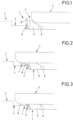
- a pipe sealing profile 1 shows a sealing arrangement in which a pipe sealing profile 1 is arranged as a sealing ring on a pipe 2 and a pipe connection of the pipe 2 to another pipe 3 is to be produced.
- the pipe sealing profile 1 is located on a spigot end of the pipe 2 immediately in front of a shoulder 4 which is created in the wall cross-section of the pipe 2.
- Paragraph 4 represents an axial displacement lock for the pipe sealing profile 1. In this way, the pipe sealing profile 1 cannot be shifted too far to the rear, i.e. in 1 to the left when an adjacent pipe exerts axial, rearward thrust forces on the pipe sealing profile 1 during the making of a pipe connection.
- the pipe sealing profile 1 has a sealing section 5 made of a first elastomeric material, the sealing section 5 being designed to be comparatively soft and, in particular, designed to be compressible.
- a front end 6 of the pipe sealing profile 1 consists of a comparatively harder material.
- a support shoulder 7, which is arranged behind the sealing section 5, consists of this second, comparatively harder material.
- the support shoulder 7 is configured as a flag that is aligned in an upright position. It has a solid upper support area 8 and a notched hinge portion 9 therebelow. Below the hinge portion 9 the support shoulder 7 is connected to the sealing portion 5 .
- the entire pipe sealing profile 1 has been produced in a multi-component extrusion process, for example with a softer material for the sealing section 5 and a second, harder material for the front end 6 and the supporting shoulder 7.
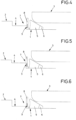
- FIGS. 4 to 6 show sealing assemblies in a similar view 1 , Each with the same pipe sealing profile 1, but with three differently configured pipes 2, which namely have different heights paragraphs 4.
- the height of the hinge section 9 allows the use of the same pipe sealing profile 1 by the support shoulder 7 can be folded at different heights, each adapted to the height of paragraph 4, from its ready position to the position of use.
- FIG. 7 shows in accordance with the Figures 1 to 6 the same pipe sealing profile 1, but in this embodiment in a groove 10 which is arranged circumferentially in the wall of the pipe 2.
- the groove 10 is delimited by a front bank 18 and by a rear bank 19 .
- the two banks 18 and 19 act as displacement safeguards for the pipe sealing profile 1 in both axial directions, so that the pipe sealing profile 1 is not shifted forward in an undesired manner, for example, if an initially established pipe connection is loosened and a second pipe moves relative to the Tube 2 moves in the axial direction forward. Since these pull-out forces acting forward are usually lower than the shearing forces when making a pipe connection, and in order to facilitate the insertion of the pipe sealing profile 1 into the groove 10, the front edge 18 is lower than the rear edge 19 in relation to the bottom of the groove.
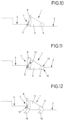
- FIG 8 shows an embodiment in which the support area 8 is profiled and has support beads 11 on which another pipe 3 can be placed.
- FIG 9 shows a further development of the embodiment of FIG 8 .
- the support area 8 is provided with an anti-slip profile 12 where its underside is when the support area 8 rests on the shoulder 4 in its position of use.
- FIG. 10 shows an embodiment in which the support shoulder 7 is also aligned upright when it is in its ready position, but runs obliquely and the rear end of the sealing portion 5 abuts. In this way it is avoided that dirt or other foreign matter penetrates into the gap between the sealing section 5 and the supporting shoulder 7 before the pipe connection is made.
- FIG. 11 shows an embodiment in which the pipe sealing profile 1 is in turn arranged in a groove 10 which is provided in the spigot end of a pipe 2.
- the support shoulder 7 is also in contact with the sealing section 5 in this exemplary embodiment.
- the support area 8 is designed on the one hand with a greater material thickness and on the other hand is provided with a guide bevel 14 . This becomes effective when, during the production of the pipe connection, the other pipe 3 has partially compressed the sealing section 5 and comes into contact with the support area 8 in the area of this guide bevel 14 . Due to the arrangement in the groove 10, the front end 6 of the pipe sealing profile 1 dips so deeply into the wall material of the pipe 2 that it forms a run-on slope 15 for the other pipe 3.
- the pipe sealing profile 1 is arranged as an integrated seal in a socket end of the pipe 2.
- the pipe sealing profile 1 has anchoring feet 16 which extend downwards into the wall of the pipe 2 and have a cross section which widens downwards.
- the two anchoring feet 16 are provided where the pipe sealing profile 1 has a harder material than in the sealing section 5.
- the support shoulder 7 is not designed as a straight, upwardly projecting lug, but rather as a ring.
- the cross-section of the ring is not closed but is interrupted by a slot 17 .
- the support shoulder 7 When the other pipe 3 is slid onto the pipe 2 to produce a pipe connection, it hits the upper area of the support shoulder 7 and displaces this upper area—namely the support area 8—onto the shoulder 4 of the pipe 2.
- the support shoulder 7 is designed as a straight flag
- the deformation or folding of the support shoulder 7 takes place below the support area 8 , namely in an area of the ring which initially runs upright and borders the sealing section 5 .
- the support area 8, which also extends in a curved manner may also be deformed.
- the support area 8 when the other tube 3 rests on the support area 8 , the support area 8 is deformed from its curved shape to a straight shape when it is pressed onto the shoulder 4 .
Landscapes
- Engineering & Computer Science (AREA)
- General Engineering & Computer Science (AREA)
- Mechanical Engineering (AREA)
- Joints With Sleeves (AREA)
- Gasket Seals (AREA)
Description
- Die Erfindung betrifft ein Rohrdichtungsprofil nach dem Oberbegriff des Anspruchs 1.
- Aus der
DE 20 2015 101 734 U1 und derEP 1 477 718 A2 ist jeweils ein gattungsgemäßes Rohrdichtungsprofil bekannt. Im Wandquerschnitt eines Rohres, welches typischerweise aus einem mineralischen Werkstoff wie Beton besteht, ist ein Absatz geformt, auf welchem die Stützschulter aufliegt. Wenn der komprimierbare Dichtungsabschnitt des Rohrdichtungsprofils unter Last komprimiert wird, beispielsweise weil Scherkräfte auf das Rohr oder ein zweites, mit diesem Rohr verbundenes Rohr einwirken, wird die Verpressung des Dichtungsabschnitts begrenzt, da einerseits die Stützschulter härter ausgestaltet ist als der Dichtungsabschnitt, also einen höheren Widerstand gegen einwirkende Druckkräfte aufweist, und da andererseits der erwähnte Absatz im Wandquerschnitt eine Relativbewegung der beiden Rohre quer zu ihrer Längsachse begrenzt. Im Rahmen des vorliegenden Vorschlags wird davon ausgegangen, dass das Rohrdichtungsprofil als Dichtungsring an einem Rohr angeordnet ist, während das erwähnte zweite Rohr als "das benachbarte Rohr" oder als "das andere Rohr" bezeichnet wird. - In diesem Zusammenhang wird davon ausgegangen, dass das Rohrdichtungsprofil in der Weise ausgerichtet ist, dass sich der Dichtungsabschnitt von einer Basis nach oben bis in eine erste Höhe erstreckt, und dass die Stützschulter in einer zweiten, vergleichsweise niedrigeren Höhe verläuft. Wenn das Rohrdichtungsprofil zu einem Dichtungsring verarbeitet ist, der auf einem Spitzende eines Rohres oder in einer Muffe eines Rohres montiert werden kann, stimmen derartige Richtungsangaben wie "oben" oder "unten" natürlich nur für einen bestimmten Abschnitt des Ringumfangs. Vor der Konfektionierung zu einem geschlossenen Dichtungsring jedoch wird das Rohrdichtungsprofil beispielsweise als geradlinig verlaufender Strang aus einem Elastomerwerkstoff bereitgestellt, und technische Zeichnungen, wie sie zur Beschreibung des Rohrdichtungsprofils üblich sind und beispielsweise auch in Verkaufsunterlagen verwendet werden, zeigen typischerweise einen Querschnitt durch das Rohrdichtungsprofil, wobei der Profilquerschnitt in der oben beschriebenen Weise ausgerichtet ist.
- Ebenso werden im Rahmen des vorliegenden Vorschlags Richtungsangaben wie "vorne" oder "hinten" verwendet. Bei diesen Richtungsangaben wird der Teil des Rohrdichtungsprofils, der als erstes in Kontakt mit einem benachbarten Rohr gerät, wenn zwei Rohre miteinander verbunden werden, als der vordere Teil des Rohrdichtungsprofils bezeichnet. Es handelt sich also bei der Vorderseite des Rohrdichtungsprofils stets um die Seite, die zum benachbarten Ende des Rohrs weist, wenn das Rohrdichtungsprofil zu einem Dichtungsring verarbeitet und auf dem Spitzende bzw. in der Muffe des Rohres montiert ist. Dementsprechend befindet sich die Stützschulter "hinter" dem Dichtungsabschnitt des Rohrdichtungsprofils.
- Aufgrund von Fertigungstoleranzen können in den Wandquerschnitten der hergestellten Rohre die erwähnten Absätze unterschiedlich hoch ausgeprägt sein. Bei unterschiedlichen Rohrdurchmessern - also bei der Herstellung von Rohren mit unterschiedlichen Nenndurchmessern - können ebenfalls unterschiedlich hohe Absätze im jeweiligen Wandquerschnitt vorgesehen sein. Für die Herstellung von Rohrdichtungsprofilen bedeutet dies eine Vielzahl unterschiedlicher Querschnittsgeometrien, was die Herstellungskosten aufgrund der Vielzahl an unterschiedlichen erforderlichen Formwerkzeugen nachteilig beeinflusst.
- Aus der
DE 10 2010 056 448 B3 ist eine Rohrverbindungsanordnung bekannt, die eine Verbindung von zwei Rohrelementen betrifft, wie sie insbesondere beim Verbinden von Lüftungsrohren zum Einsatz kommt. Dabei dient ein als Ring ausgestaltetes Dichtungsmittel gleichzeitig auch als Arretierungsmittel zum Arretieren des ersten und zweiten Rohrelements aneinander. Der Ring weist einen Grundkörper auf, von dem jeweils ein Dichtungs- und ein Arretierungsabschnitt nach oben ragen. Der Arretierungsabschnitt ist vor dem Dichtungsabschnitt angeordnet und wirkt mit einem Verriegelungselement zusammen, das an dem anderen Rohr als nach innen ragender Vorsprung ausgestaltet ist. Wenn die Verbindung der beiden Rohrelemente hergestellt wird und das andere Rohr auf den Ring des ersten Rohrs aufgeschoben wird, hintergreift zunächst das Verriegelungselement des anderen Rohrs den Arretierungsabschnitt des Dichtungsmittels. Beim weiteren Aufschieben legt sich dann der Dichtungsabschnitt des Dichtungsmittels an das andere Rohr an und bewirkt die gewünschte Abdichtung. Dadurch, dass die Arretierung der beiden Rohrabschnitte mithilfe des Elastomerwerkstoffs des Dichtungsmittels bewirkt wird, wird eine sowohl zuverlässige als auch flexible und auch wieder lösbare Verbindung von Rohren ermöglicht. - Aus der
DE 42 29 609 A1 ist eine Abdichtung zwischen zwei ineinandersteckbaren Teilen, insbesondere Rohren bekannt, wobei die Dichtung einen komprimierbaren Elastomerkörper aufweist sowie ein Einknüpfteil, welches als Gleitmantel auf dem Elastomerkörper aufliegt und einen Anker aufweist, mit welchem es in den Elastomerkörper eingeknüpft werden kann. Durch die Bereitstellung unterschiedlicher Einknüpfteile können bei Verwendung desselben Elastomerkörpers unterschiedliche Dichtungen geschaffen werden, so dass die Dichtfunktion der Abdichtung zwischen den Teilen individuell beeinflusst werden kann. - Der Erfindung liegt die Aufgabe zugrunde, ein gattungsgemäßes Rohrdichtungsprofil dahingehend zu verbessern, dass es für die Anwendung an Rohren mit unterschiedlich hohen Absätzen geeignet ist. Weiterhin liegt der Neuerung die Aufgabe zugrunde, eine Dichtungsanordnung anzugeben, welche möglichst wirtschaftlich eine zuverlässige Abdichtung auch bei unterschiedlichen Querschnittsgeometrien der Rohrwandungen ermöglicht.
- Diese Aufgabe wird durch ein Rohrdichtungsprofil nach Anspruch 1 und eine Dichtungsanordnung nach Anspruch 12 gelöst. Vorteilhafte Ausgestaltungen der Erfindung sind in den Unteransprüchen beschrieben.
- Die Erfindung schlägt mit anderen Worten vor, keine Querschnittsgeometrie des Rohrdichtungsprofils in der Art fest vorzugeben, dass die Stützschulter liegend ausgerichtet und in einer bestimmten Höhe angeordnet ist - und somit auf eine bestimmte Ausgestaltung des Absatzes im Wandquerschnitt eines Rohres angewiesen ist. Vielmehr ist vorschlagsgemäß die Stützschulter im Querschnitt des Rohrdichtungsprofils stehend ausgerichtet. Dies ist nicht die Ausrichtung, in welcher die Stützschulter ihre Stützwirkung gegen Scherkräfte entfaltet, so dass diese stehende Ausrichtung auch als Bereitschaftsstellung der Stützschulter bezeichnet ist.
- In ihrer Bereitschaftsstellung ragt die Stützschulter also radial nach außen, wenn das vorschlagsgemäße Rohrdichtungsprofil zu einem Dichtungsring verarbeitet ist, der auf dem Spitzende eines Rohrs montiert ist. Oder sie ragt radial nach innen, wenn das Rohrdichtungsprofil zu einem Dichtungsring verarbeitet ist, der im Muffenende eines Rohrs angeordnet ist. Spätestens bei der Verbindung des betreffenden Rohrs mit einem benachbarten Rohr wird daher die radial bzw. stehend ausgerichtete Stützschulter von dem benachbarten Rohr erfasst und nach "hinten" in eine axial bzw. liegend ausgerichtete Gebrauchsstellung umgeklappt und auf den erwähnten Absatz im Wandquerschnitt des Rohrs gelegt. Alternativ dazu, die Stützschulter erst während der Herstellung der Rohrverbindung durch den Kontakt mit einem benachbarten Rohr umzuklappen, kann dieses Umklappen ggf. bereits vorher durch einen separaten Montageschritt erfolgen.
- In der Gebrauchsstellung befindet sich die Stützschulter tiefer als das obere Ende des Dichtungsabschnitts. Sie erlaubt daher eine gewisse, definierte Kompression des Dichtungsabschnitts in radialer Richtung und kann zur Begrenzung dieser Kompression ihre Stützwirkung gegen Scherkräfte entfalten.
- Jedenfalls kann die Stützschulter des vorschlagsgemäß ausgestalteten Rohrdichtungsprofils problemlos bei Rohren mit unterschiedlich hoch ausgestalteten Absätzen in deren jeweiligen Wandquerschnitten verwendet werden. Die Stützschulter wird nämlich erst während des Umklappvorgangs an die jeweilige Querschnittsgeometrie des Rohrs angepasst. Nachdem die Stützschulter in ihre Gebrauchsstellung umgeklappt ist, verhindert sie zuverlässig einen unmittelbaren Kontakt der beiden Rohre miteinander, beispielsweise "Beton auf Beton", welcher ansonsten angesichts der Oberflächenrauhigkeit der beiden Rohre zu unerwünschten punktuellen Druckspitzen und zu einer Schädigung der Rohre führen könnte.
- Ein oberer Bereich der Stützschulter - bei ihrer stehenden Ausrichtung in ihrer Bereitschaftsstellung - wird als deren Stützbereich bezeichnet, weil nämlich dieser obere Bereich nach dem Umklappen in die Gebrauchsstellung auf dem Absatz im Wandquerschnitt des Rohrs aufliegt und zur Abstützung gegen Scherkräfte dient. Um die im Betrieb auftretenden, ggf. hohen Kräfte aufnehmen zu können, kann dieser Stützbereich vorteilhaft vergleichsweise hart ausgestaltet sein, beispielsweise härter als der Dichtungsabschnitt des Rohrdichtungsprofils. Um angesichts dieser harten Ausgestaltung der Stützschulter das Umklappen aus der Bereitschaft- in die Gebrauchsstellung zu erleichtern, kann die Stützschulter unterhalb des Stützbereichs vorteilhaft einen Bereich aufweisen, der eine Verformung des Stützabschnitts erleichtert und daher als Scharnierabschnitt bezeichnet ist.
- Der Scharnierabschnitt kann beispielsweise durch eine bestimmte Querschnittsgeometrie der Stützschulter in diesem Bereich geschaffen werden, beispielsweise indem die Stützschulter im Scharnierabschnitt einen verringerten Materialquerschnitt aufweist und beispielsweise mäanderförmig oder serpentinenartig verläuft. Alternativ dazu - oder auch zusätzlich dazu - kann die Stützschulter in ihrem Scharnierabschnitt aus einem anderen Material bestehen als in ihrem Stützbereich, beispielsweise aus einem weicheren Material. Im sogenannten 2K-Extrusionsverfahren werden in an sich bekannter Weise zwei unterschiedliche Materialien gleichzeitig extrudiert, um innerhalb des Rohrdichtungsprofils Bereiche aus zwei unterschiedlichen Werkstoffen zu schaffen, so dass das Rohrdichtungsprofil in diesem 2K-Extrusionsverfahren hergestellt werden kann.
- Vorteilhaft kann im Querschnitt des Rohrdichtungsprofils vor dem Dichtungsabschnitt eine Anlaufschräge angeordnet sein, die bei Herstellung einer Rohrverbindung das jeweils andere Rohr führt und somit die Herstellung der Rohrverbindung erleichtert. Dabei kann vorteilhaft diese Anlaufschräge härter ausgestaltet sein als der Dichtungsabschnitt. Beispielsweise können auch hier mittels des 2K-Extrusionsverfahrens unterschiedliche Werkstoffe Verwendung finden, oder der Dichtungsabschnitt und die Anlaufschräge können durch die Anordnung von Hohlkammern bzw. durch deren Vermeidung unterschiedlich hart ausgestaltet sein. Bei der Herstellung im 2K-Extrusionsverfahrens kann beispielsweise der oben erwähnte harte Bereich der Stützschulter sowie die oben erwähnte Anlaufschräge, beispielsweise das vordere Ende des Rohrdichtungsprofils, aus dem gleichen, härteren Material und der Dichtungsabschnitt aus dem vergleichsweise weicheren Material gefertigt werden.
- Es kann davon ausgegangen werden, dass während der Herstellung der Rohrverbindung das andere Rohr den Dichtungsabschnitt des Rohrdichtungsprofils komprimiert und anschließend gegen die Stützschulter gerät und diese aus ihrer Bereitschaftsstellung in ihrer Gebrauchsstellung umklappt. Dabei ist wünschenswert, dass die Stützschulter entlang dem gesamten Umfang eines Dichtungsrings von dem anderen Rohr sicher erfasst und umgeklappt wird. In der Praxis ist davon auszugehen, dass die beiden Rohre nicht ideal achsgleich ausgerichtet sind, sondern einen gewissen axialen Versatz zueinander aufweisen. Um sicherzustellen, dass das andere Rohr die Stützschulter tatsächlich entlang dem gesamten Umfang des Dichtungsrings erfassen kann, kann vorteilhaft vorgesehen sein, dass die Stützschulter sich in ihrer Bereitschaftsstellung radial weiter erstreckt als der Dichtungsabschnitt des Dichtungsrings. Dementsprechend kann vorteilhaft vorgesehen sein, dass sich die Stützschulter des Rohrdichtungsprofils bis in eine dritte Höhe erstreckt, die nicht nur größer ist als die zweite Höhe, welche die Stützschulter in ihrer Gebrauchsstellung einnimmt, sondern die auch größer ist als die erste Höhe, bis in welche sich nämlich der Dichtungsabschnitt erstreckt.
- In einer Ausgestaltung kann vorteilhaft vorgesehen sein, dass die Stützschulter als separates Bauteil ausgestaltet ist. Auf diese Weise kann ein herkömmliches Rohrdichtungsprofil, wie es beispielsweise für eine Keildichtung verwendet wird, weiter verwendet und zu einem vorschlagsgemäßen Rohrdichtungsprofil weiterentwickelt werden, indem es mit der zusätzlich vorgesehenen Stützschulter kombiniert wird.
- Dabei kann beispielsweise vorgesehen sein, dass diese separate Stützschulter an dem Dichtungsabschnitt befestigt ist. So wird an der Baustelle eine einfache Montage des Dichtungsrings ermöglicht, indem dort lediglich ein einzelnes - nämlich zweiteiliges - Bauteil gehandhabt werden muss. Die Befestigung kann dadurch erfolgen, dass die Stützschulter mit dem übrigen Dichtungsprofil verklebt bzw. vulkanisiert ist. Oder es kann eine formschlüssige Verbindung in Art einer Nut-und-Feder-Verbindung vorgesehen sein, was durch eine Änderung an der Produktionsform des herkömmlichen Rohrdichtungsprofils erreicht werden kann, die mit einem vergleichsweise geringen Aufwand erzielbar ist. Insbesondere können so unterschiedliche herkömmliche Rohrdichtungsprofile mit dem gleichen oder wenigen unterschiedlichen separat hergestellten Stützschulterprofilen kombiniert werden, so dass mit einem geringen Fertigungsaufwand eine Vielzahl unterschiedlicher Querschnittsgeometrien vorschlagsgemäße Rohrdichtungsprofile geschaffen werden kann.
- Das vorschlagsgemäße Rohrdichtungsprofils kann zur Schaffung einer integrierten Dichtung genutzt werden, indem vorteilhaft am Dichtungsabschnitt und / oder an der Stützschulter jeweils unten Verankerungsfüße angeformt sind. Um einen zuverlässigen Halt im Werkstoff eines Rohres sicherzustellen, kann beispielsweise vorgesehen sein, dass sich der Querschnitt der Verankerungsfüße jeweils nach unten erweitert.
- In einer ersten Ausgestaltung kann vorgesehen sein, dass die Stützschulter in Art einer "Fahne" in ihrer Bereitschaftsstellung stehend ausgerichtet ist. In einer anderen Ausgestaltung kann allerdings auch vorgesehen sein, dass die Stützschulter nicht eine mehr oder weniger geradlinig verlaufende Fahne bildet, sondern im Querschnitt gesehen einen Ringquerschnitt aufweist. Dieser Ringquerschnitt ist nicht als geschlossener Ring ausgestaltet und umgibt eine Hohlkammer, sondern weist vielmehr einen Schlitz auf, welcher den Ring unterbricht. Je nachdem, wo im Umfang des Rings der Schlitz vorgesehen ist, kann bei einem Kontakt mit dem anderen Rohr der obere Umfangsabschnitt des Rings lediglich verschoben werden, oder aber ggf. um annähernd 180° geschwenkt werden.
- Eine vorschlagsgemäße Dichtungsanordnung besteht darin, dass bei einem Rohr, welches ein als Muffe oder als Spitzende ausgestaltetes Rohrende aufweist, ein vorschlagsgemäß ausgestaltetes Rohrdichtungsprofil in Form eines geschlossenen Rings nahe des Rohrendes angeordnet ist.
- Eine solche Dichtungsanordnung kann unter Verwendung eines einstückigen Rohrdichtungsprofils geschaffen werden. Es kann jedoch auch vorgesehen sein, dass die Stützschulter als separates Element ausgestaltet ist welches hinter dem Dichtungsabschnitt angeordnet ist. Beispielsweise kann, wie weiter oben erläutert, dieses separate Element der Stützschulter mit einem den Dichtungsabschnitt aufweisenden herkömmlichen Rohrdichtungsprofil verbunden sein.
- Alternativ dazu kann jedoch vorgesehen sein, dass die Stützschulter ohne Verbindung zu dem Dichtungsabschnitt hinter dem Dichtungsabschnitt angeordnet ist. In diesem Fall kann nach wie vor ein herkömmliches Rohrdichtungsprofil verwendet werden, beispielsweise eine handelsübliche Keildichtung. An der Baustelle wird daher am Rohrende zunächst die vorschlagsgemäß vorgesehene Stützschulter montiert und anschließend das erwähnte herkömmliche Rohrdichtungsprofil. Bei Erzeugung einer Rohrverbindung verformt das andere Rohr die Stützschulter, so dass diese aus ihrer Bereitschaftsstellung in ihre Gebrauchsstellung gebracht wird.
- Ausführungsbeispiele der Neuerung werden anhand der rein schematischen Darstellungen nachfolgend näher erläutert. Dabei zeigt
- Fig. 1 bis 3
- jeweils einen Querschnitt durch eine Dichtungsanordnung bei der Herstellung einer Rohrverbindung in drei unterschiedlichen Relativstellungen der beiden Rohre zueinander,
- Fig. 4 bis 6
- Querschnitte durch drei unterschiedliche Dichtungsanordnungen mit unterschiedlich hohen Absätzen in den jeweiligen Wandquerschnitten der Rohre, und
- Fig. 7 bis 13
- Querschnitte durch unterschiedliche Ausführungsbeispiele von Rohrdichtungsprofilen, jeweils als Dichtungsring an einem Rohr montiert.
-
Fig. 1 zeigt eine Dichtungsanordnung, bei welcher ein Rohrdichtungsprofil 1 als Dichtungsring auf einem Rohr 2 angeordnet ist und eine Rohrverbindung des Rohrs 2 mit einem anderen Rohr 3 hergestellt werden soll. Bei dem dargestellten Ausführungsbeispiel befindet sich das Rohrdichtungsprofil 1 auf einem Spitzende des Rohrs 2 unmittelbar vor einem Absatz 4, der im Wandquerschnitt des Rohrs 2 geschaffen ist. Der Absatz 4 stellt eine axiale Verschiebesicherung für das Rohrdichtungsprofil 1 dar. So kann das Rohrdichtungsprofil 1 nicht unerwünscht weit nach hinten verlagert werden, also inFig. 1 nach links, wenn ein benachbartes Rohr während der Herstellung einer Rohrverbindung axiale, nach hinten gerichtete Schubkräfte auf das Rohrdichtungsprofil 1 ausübt. - Das Rohrdichtungsprofil 1 weist einen Dichtungsabschnitt 5 aus einem ersten Elastomerwerkstoff auf, wobei der Dichtungsabschnitt 5 vergleichsweise weich ausgestaltet und insbesondere komprimierbar ausgestaltet ist. Ein vorderes Ende 6 des Rohrdichtungsprofils 1 besteht aus einem im Vergleich dazu härteren Werkstoff. Auch eine Stützschulter 7, die hinter dem Dichtungsabschnitt 5 angeordnet ist, besteht aus diesem zweiten, vergleichsweise härteren Werkstoff. Die Stützschulter 7 ist bei diesem Ausführungsbeispiel als stehend ausgerichtete Fahne ausgestaltet. Sie weist einen massiven oberen Stützbereich 8 auf sowie darunter einen mit Einkerbungen versehenen Scharnierabschnitt 9. Unterhalb des Scharnierabschnitts 9 ist die Stützschulter 7 mit dem Dichtungsabschnitt 5 verbunden. Das gesamte Rohrdichtungsprofils 1 ist in einem mehrkomponentigen Extrusionsverfahren hergestellt worden, beispielsweise mit einem weicheren Werkstoff für den Dichtungsabschnitt 5 und einem zweiten, härteren Werkstoff für das vordere Ende 6 und die Stützschulter 7.
- In
Fig. 1 befindet sich das andere Rohr 3 kurz vor einem Kontakt mit dem Rohrdichtungsprofil 1. Zur Herstellung der Rohrverbindung wird dieses andere Rohr 3 mit seinem Muffenende weiter nach links auf das Spitzende des Rohrs 2 aufgeschoben, wie anhand derFig. 2 und 3 ersichtlich. -
Fig. 2 zeigt, dass beim weiteren Aufschieben des anderen Rohrs 3 der Dichtungsabschnitt 5 komprimiert und verformt wird. Außerdem wird die Stützschulter 7 aus ihrer aufrechten Bereitschaftsstellung derFig. 1 nach hinten umgeklappt, so dass ihr Stützbereich 8 über den Absatz 4 gelegt wird. Der Scharnierabschnitt 9 erleichtert durch seine Geometrie die Verformung der Stützschulter 7. -
Fig. 3 zeigt die Situation, dass das andere Rohr 3 sich abgesenkt hat. Die Bewegung des anderen Rohrs 3 in Bezug auf das Rohr 2 wird durch den Stützbereich 8 begrenzt, welcher sich auf den Absatz 4 aufgelegt hat. Hierdurch wird die Verpressung des Dichtungsabschnitts 5 ebenfalls begrenzt, so dass eine optimale Dichtungswirkung dadurch gewährleistet ist, dass eine übermäßige, nachteilige Verpressung des Dichtungsabschnitts 5 vermieden wird. - Die
Fig. 4 bis 6 zeigen Dichtungsanordnungen in einer Ansicht ähnlichFig. 1 , und zwar mit jeweils dem gleichen Rohrdichtungsprofil 1, jedoch mit drei unterschiedlich ausgestalteten Rohren 2, die nämlich unterschiedlich hohe Absätze 4 aufweisen. - Die Höhe des Scharnierabschnitts 9 ermöglicht die Verwendung des gleichen Rohrdichtungsprofils 1, indem die Stützschulter 7 in unterschiedlicher Höhe, jeweils angepasst an die Höhe des Absatzes 4, aus ihrer Bereitschaftsstellung in die Gebrauchsstellung umgeklappt werden kann.
-
Fig. 7 zeigt in Übereinstimmung mit denFig. 1 bis 6 das gleiche Rohrdichtungsprofil 1, bei diesem Ausführungsbeispiel allerdings in einer Nut 10, welche umlaufend in der Wand des Rohrs 2 angeordnet ist. Die Nut 10 wird durch ein vorderes Ufer 18 sowie durch ein hinteres Ufer 19 begrenzt. Die beiden Ufer 18 und 19 wirken als Verschiebesicherungen für das Rohrdichtungsprofil 1 in beiden axialen Richtungen, so dass das Rohrdichtungsprofil 1 beispielsweise auch dann nicht in unerwünschter Weise nach vorn verlagert wird, wenn eine zunächst hergestellte Rohrverbindung gelockert wird und ein zweites Rohr sich relativ zu dem Rohr 2 in axialer Richtung nach vorn bewegt. Da diese nach vorn wirkenden Auszugskräfte üblicherweise geringer sind als die Schubkräfte bei der Herstellung einer Rohrverbindung, und um das Einsetzen des Rohrdichtungsprofils 1 in die Nut 10 zu erleichtern, ist das vordere Ufer 18 gegenüber dem Nutgrund niedriger als das hintere Ufer 19. -
Fig. 8 zeigt ein Ausführungsbeispiel, bei welchem der Stützbereich 8 profiliert ist und Auflagewülste 11 aufweist, auf welche sich ein anderes Rohr 3 auflegen kann. -
Fig. 9 zeigt eine Weiterentwicklung des Ausführungsbeispiels derFig. 8 . Dort, wo sich seine Unterseite befindet, wenn der Stützbereich 8 in seiner Gebrauchsstellung auf dem Absatz 4 aufliegt, ist der Stützbereich 8 mit einer rutschhemmende Profilierung 12 versehen. -
Fig. 10 zeigt ein Ausführungsbeispiel, bei welchem die Stützschulter 7 zwar ebenfalls stehend ausgerichtet ist, wenn sie sich in ihrer Bereitschaftsstellung befindet, dabei aber schräg verläuft und dem hinteren Ende des Dichtungsabschnitts 5 anliegt. Auf diese Weise wird vermieden, dass vor der Herstellung der Rohrverbindung Schmutz oder andere Fremdstoffe in den Spalt zwischen dem Dichtungsabschnitt 5 und der Stützschulter 7 eindringen. -
Fig. 11 zeigt ein Ausführungsbeispiel, bei welchem das Rohr Dichtungsprofil 1 wiederum in einer Nut 10 angeordnet ist, die im Spitzende eines Rohrs 2 vorgesehen ist. Auch bei diesem Ausführungsbeispiel liegt die Stützschulter 7 dem Dichtungsabschnitt 5 an. Im Vergleich zu den anderen Ausführungsbeispielen ist in diesem Fall der Stützbereich 8 einerseits mit einer grö-βeren Materialstärke ausgeführt und andererseits mit einer Führungsschräge 14 versehen. Diese wird dann wirksam, wenn bei der Herstellung der Rohrverbindung das andere Rohr 3 den Dichtungsabschnitt 5 teilweise komprimiert hat und im Bereich dieser Führungsschräge 14 gegen den Stützbereich 8 gerät. Durch die Anordnung in der Nut 10 taucht das vordere Ende 6 des Rohrdichtungsprofils 1 so tief in das Wandmaterial des Rohrs 2 ein, dass es eine Anlaufschräge 15 für das andere Rohr 3 bildet. -
Fig. 12 zeigt ein Ausführungsbeispiel, bei welchem das Rohrdichtungsprofil 1 als integrierte Dichtung in einem Muffenende des Rohrs 2 angeordnet ist. Zu diesem Zweck weist das Rohrdichtungsprofil 1 Verankerungsfüße 16 auf, die sich nach unten in die Wand des Rohrs 2 hinein erstrecken und einen Querschnitt aufweisen, der sich nach unten erweitert. Die beiden Verankerungsfüße 16 sind jeweils dort vorgesehen, wo das Rohrdichtungsprofil 1 ein härteres Material aufweist als im Dichtungsabschnitt 5. -
Fig. 13 zeigt ein Ausführungsbeispiel, bei welchem die Stützschulter 7 nicht als geradlinige, nach oben ragende Fahne ausgestaltet ist, sondern vielmehr als Ring. Der Ringquerschnitt verläuft nicht geschlossen, sondern ist durch einen Schlitz 17 unterbrechen. Wenn das andere Rohr 3 zur Herstellung einer Rohrverbindung auf das Rohr 2 aufgeschoben wird, gerät es gegen den oberen Bereich der Stützschulter 7 und verschiebt diesen oberen Bereich - nämlich den Stützbereich 8 - auf den Absatz 4 des Rohrs 2. Wie auch bei den Ausführungsbeispielen, bei denen die Stützschulter 7 als geradlinige Fahne ausgestaltet ist, erfolgt die Verformung bzw. das Umklappen der Stützschulter 7 unterhalb des Stützbereiches 8, nämlich in einem Bereich des Rings, der zunächst aufrecht verläuft und an den Dichtungsabschnitt 5 angrenzt. Zusätzlich wird ggf. auch noch der ebenfalls gebogen verlaufende Stützbereich 8 verformt. Insbesondere dann, wenn sich das andere Rohr 3 auf den Stützbereich 8 auflegt, wird der Stützbereich 8 von seinem gebogenen zu einem geradlinigen Verlauf verformt, wenn er auf den Absatz 4 gepresst wird. -
- 1
- Rohrdichtungsprofil
- 2
- Rohr
- 3
- Anderes Rohr
- 4
- Absatz
- 5
- Dichtungsabschnitt
- 6
- Vorderes Ende
- 7
- Stützschulter
- 8
- Stützbereich
- 9
- Scharnierabschnitt
- 10
- Nut
- 11
- Auflagewülste
- 12
- Rutschhemmende Profilierung
- 14
- Führungsschräge
- 15
- Anlaufschräge
- 16
- Verankerungsfuß
- 17
- Schlitz
- 18
- Vorderes Ufer
- 19
- Hinteres Ufer
Claims (16)
- Rohrdichtungsprofil (1), das dazu bestimmt ist, zu einem Dichtungsring verarbeitet zu werden, der auf einem Spitzende eines Rohres oder in einer Muffe eines Rohres montiert werden kannund dessen Querschnitt folgende Merkmale aufweist:• einen komprimierbaren Dichtungsabschnitt (5),der von einem ersten, so genannten vorderen Ende (6) des Querschnitts nach hinten ansteigend zu einer ersten Höhe ansteigend verläuft,wobei der Teil des Rohrdichtungsprofils, der dazu bestimmt ist, bei einem zu einem Dichtungsring verarbeiteten und auf dem Spitzende bzw. in der Muffe des Rohres montierten Rohrdichtungsprofil als erstes in Kontakt mit einem benachbarten Rohr zu geraten, wenn zwei Rohre miteinander verbunden werden, als der vordere Teil des Rohrdichtungsprofils bezeichnet wird,und wobei Richtungsangaben wie "oben" oder "unten" nur für einen bestimmten Abschnitt des Ringumfangs eines auf einem Spitzende oder in einer Muffe eines Rohres montierten Dichtungsrings zutreffen,• und eine Stützschulter (7),
die hinter dem Dichtungsabschnitt (5) angeordnet ist und die sich im Gebrauch bis zu einer zweiten, geringeren Höhe erstreckt als der Dichtungsabschnitt (5),• derart, dass die Stützschulter (7) unter einer von oben nach unten wirkenden Belastung des Rohrdichtungsprofils (1) eine Verpressung des Dichtungsabschnitts (5) begrenzt,dadurch gekennzeichnet,dass die Stützschulter (7) des zu einem Dichtungsring verarbeiteten und auf dem Spitzende bzw. in der Muffe des Rohres montierten Rohrdichtungsprofils aus einer stehend ausgerichteten Bereitschaftsstellung in eine liegend ausgerichtete Gebrauchsstellung klappbar ist, in welcher sie in der geringeren Höhe als der Dichtungsabschnitt (5) verläuft. - Rohrdichtungsprofil nach Anspruch 1,
dadurch gekennzeichnet,dass die Stützschulter (7) in ihrer Bereitschaftsstellung einen oberen Stützbereich (8) aufweist,und dass sie unterhalb des Stützbereichs (8) einen als Scharnierabschnitt (9) bezeichneten Bereich aufweist, der leichter verformbar als der Stützabschnitt (8) ausgestaltet ist. - Rohrdichtungsprofil nach Anspruch 1 oder 2,
dadurch gekennzeichnet,
dass im Querschnitt vor dem Dichtungsabschnitt (5) eine Anlaufschräge (15) angeordnet ist, die härter ausgestaltet ist als der Dichtungsabschnitt (5). - Rohrdichtungsprofil nach einem der vorhergehenden Ansprüche,
dadurch gekennzeichnet,
dass die Stützschulter (7) sich in ihrer Bereitschaftsstellung bis in eine dritte Höhe erstreckt, welche größer ist als die erste Höhe des Dichtungsabschnitts (5). - Rohrdichtungsprofil nach einem der vorhergehenden Ansprüche,
dadurch gekennzeichnet,
dass die Stützschulter (7) als separates Bauteil ausgestaltet ist. - Rohrdichtungsprofil nach Anspruch 5,
dadurch gekennzeichnet,
dass die Stützschulter (7) an dem Dichtungsabschnitt (5) befestigt ist. - Rohrdichtungsprofil nach einem der vorhergehenden Ansprüche,
dadurch gekennzeichnet,
dass unten am Dichtungsabschnitt (5) und / oder an der Stützschulter (7) Verankerungsfüße (16) angeformt sind. - Rohrdichtungsprofil nach einem der vorhergehenden Ansprüche,
dadurch gekennzeichnet,dass die Stützschulter (7), im Querschnitt gesehen, einen Ringquerschnitt aufweistsowie einen den Ring unterbrechenden Schlitz (17). - Rohrdichtungsprofil nach einem der vorhergehenden Ansprüche,
dadurch gekennzeichnet,
dass der Dichtungsabschnitt (5) eine erste Härte aufweist und die Stützschulter (7) eine zweite Härte aufweist, welche größer ist als die Härte des Dichtungsabschnitts (5). - Rohrdichtungsprofil nach einem der vorhergehenden Ansprüche,
dadurch gekennzeichnet,
dass der Dichtungsabschnitt (5) eine erste Härte aufweist und das vordere Ende (6) eine zweite Härte aufweist, welche größer ist als die Härte des Dichtungsabschnitts (5). - Rohrdichtungsprofil nach den Ansprüchen 9 und 10,
dadurch gekennzeichnet,
dass die Stützschulter (7) und das vordere Ende (6) die gleiche Härte aufweisen. - Dichtungsanordnung,mit einem Rohr (2), welches ein als Muffe oder als Spitzende ausgestaltetes Rohrende aufweist,und mit einem an dem Rohrende zu einem geschlossenen Ring umlaufend angeordneten Rohrdichtungsprofil (1), welches nach einem der vorhergehenden Ansprüche ausgestaltet ist.
- Dichtungsanordnung nach Anspruch 12,
dadurch gekennzeichnet,
dass die Stützschulter (7) als separates Element ausgestaltet ist, welches hinter dem Dichtungsabschnitt (5) angeordnet ist. - Dichtungsanordnung nach Anspruch 13,
dadurch gekennzeichnet,
dass die Stützschulter (7) ohne Verbindung zu dem Dichtungsabschnitt (5) hinter diesem angeordnet ist. - Dichtungsanordnung nach einem der Ansprüche 12 bis 14,
dadurch gekennzeichnet,dass in dem Rohr (2) eine umlaufende Nut (10) verläuft, in welcher das Rohrdichtungsprofil (1) angeordnet ist,wobei die Nut (10) durch ein vorderes und ein hinteres Ufer begrenzt ist und das hintere Ufer die Aufkantung bildet. - Dichtungsanordnung nach Anspruch 15,
dadurch gekennzeichnet,
dass das vordere Ufer vom Nutgrund aus niedriger ist als das hintere Ufer.
Applications Claiming Priority (1)
| Application Number | Priority Date | Filing Date | Title |
|---|---|---|---|
| DE202018102394.2U DE202018102394U1 (de) | 2018-04-30 | 2018-04-30 | Dichtungsring mit Stützfahne |
Publications (2)
| Publication Number | Publication Date |
|---|---|
| EP3564567A1 EP3564567A1 (de) | 2019-11-06 |
| EP3564567B1 true EP3564567B1 (de) | 2023-07-19 |
Family
ID=62813309
Family Applications (1)
| Application Number | Title | Priority Date | Filing Date |
|---|---|---|---|
| EP19170479.0A Active EP3564567B1 (de) | 2018-04-30 | 2019-04-23 | Dichtungsring mit stützfahne |
Country Status (2)
| Country | Link |
|---|---|
| EP (1) | EP3564567B1 (de) |
| DE (1) | DE202018102394U1 (de) |
Family Cites Families (5)
| Publication number | Priority date | Publication date | Assignee | Title |
|---|---|---|---|---|
| DE4229609C2 (de) * | 1992-09-04 | 2003-05-08 | Forsheda Stefa Gmbh | Abdichtung zwischen zwei ineinandersteckbaren Teilen |
| AUPQ945800A0 (en) * | 2000-08-16 | 2000-09-07 | James Hardie International Finance B.V. | A seal |
| DE20307362U1 (de) * | 2003-05-12 | 2004-09-16 | Pt - Poly - Tec Gmbh Vertrieb Und Herstellung Von Dichtungssystemen | Abdichtung an Betonrohren und Schachtbauwerken |
| DE102010056448B3 (de) * | 2010-12-10 | 2012-01-12 | Oscar McAven | Rohrverbindungsanordnung |
| DE202015101734U1 (de) | 2015-04-09 | 2015-05-13 | Theodor Cordes Gmbh & Co. Kg | Integrierte Dichtung mit Scherkraft-Stützschulter |
-
2018
- 2018-04-30 DE DE202018102394.2U patent/DE202018102394U1/de active Active
-
2019
- 2019-04-23 EP EP19170479.0A patent/EP3564567B1/de active Active
Also Published As
| Publication number | Publication date |
|---|---|
| DE202018102394U1 (de) | 2018-06-15 |
| EP3564567A1 (de) | 2019-11-06 |
Similar Documents
| Publication | Publication Date | Title |
|---|---|---|
| DE60028032T2 (de) | Doppelzweckdichtung mit geringer einsteckkraft | |
| EP0273221B1 (de) | Rohrverbinder aus Muffe und Einsteckteil | |
| DE2304676A1 (de) | Werkstueck, insbesondere dichtungselement, aus elastischem material mit elastischer verstaerkung | |
| DE2546588A1 (de) | Dichtung | |
| EP1593898A1 (de) | Dichtelement | |
| DE1475683A1 (de) | Kupplungsdichtring | |
| EP0634532A2 (de) | Dichtungseinrichtung an einem Bauteil | |
| DE2613032A1 (de) | Verbindung fuer kanalabschnitte und dergleichen | |
| EP1234137A1 (de) | Dichtungseinheit | |
| EP3078884B1 (de) | Integrierte dichtung mit scherkraft-stützschulter | |
| WO2016001371A1 (de) | Montagevorrichtung | |
| EP0348870B1 (de) | Aus mehreren Stahlbetonfertigteilen zusammengefügter Baukörper in einer Spannbetonbauweise | |
| DE3136315A1 (de) | Steckmuffendichtung fuer betonrohre | |
| EP1533471B1 (de) | Gleitanker | |
| DE2614575B2 (de) | Ringgedichtete rohrverbindung | |
| DE2809307A1 (de) | Steckmuffenverbindung von rohren und rohrelementen | |
| DE202008008250U1 (de) | Eckverbinder | |
| DE202013003947U1 (de) | Dichtring und Steckmuffenverbindung für den Kanalbau | |
| EP3564567A1 (de) | Dichtungsring mit stützfahne | |
| AT9919U1 (de) | Ring zum gegenseitigen verbinden von rohren und sanitären einrichtungen | |
| CH686383A5 (de) | Verfahren zur Herstellung einer nicht verschiebbaren Dichtungsprofilleiste und nach diesem Verfahren hergestellte Leiste. | |
| DE202021105807U1 (de) | Reduzierstück, insbesondere zum abgedichteten Verbinden von zwei Rohren, und Anordnung | |
| EP2282098A2 (de) | Dichtung mit verschiebbarem Dichtungsteil | |
| DE20306091U1 (de) | Türdichtungsvorrichtung | |
| EP4108881B1 (de) | Ausgeklinkte tübbingecke |
Legal Events
| Date | Code | Title | Description |
|---|---|---|---|
| PUAI | Public reference made under article 153(3) epc to a published international application that has entered the european phase |
Free format text: ORIGINAL CODE: 0009012 |
|
| STAA | Information on the status of an ep patent application or granted ep patent |
Free format text: STATUS: THE APPLICATION HAS BEEN PUBLISHED |
|
| AK | Designated contracting states |
Kind code of ref document: A1 Designated state(s): AL AT BE BG CH CY CZ DE DK EE ES FI FR GB GR HR HU IE IS IT LI LT LU LV MC MK MT NL NO PL PT RO RS SE SI SK SM TR |
|
| AX | Request for extension of the european patent |
Extension state: BA ME |
|
| STAA | Information on the status of an ep patent application or granted ep patent |
Free format text: STATUS: REQUEST FOR EXAMINATION WAS MADE |
|
| 17P | Request for examination filed |
Effective date: 20200505 |
|
| RBV | Designated contracting states (corrected) |
Designated state(s): AL AT BE BG CH CY CZ DE DK EE ES FI FR GB GR HR HU IE IS IT LI LT LU LV MC MK MT NL NO PL PT RO RS SE SI SK SM TR |
|
| STAA | Information on the status of an ep patent application or granted ep patent |
Free format text: STATUS: EXAMINATION IS IN PROGRESS |
|
| 17Q | First examination report despatched |
Effective date: 20210430 |
|
| GRAP | Despatch of communication of intention to grant a patent |
Free format text: ORIGINAL CODE: EPIDOSNIGR1 |
|
| STAA | Information on the status of an ep patent application or granted ep patent |
Free format text: STATUS: GRANT OF PATENT IS INTENDED |
|
| INTG | Intention to grant announced |
Effective date: 20230313 |
|
| GRAS | Grant fee paid |
Free format text: ORIGINAL CODE: EPIDOSNIGR3 |
|
| GRAA | (expected) grant |
Free format text: ORIGINAL CODE: 0009210 |
|
| STAA | Information on the status of an ep patent application or granted ep patent |
Free format text: STATUS: THE PATENT HAS BEEN GRANTED |
|
| P01 | Opt-out of the competence of the unified patent court (upc) registered |
Effective date: 20230526 |
|
| AK | Designated contracting states |
Kind code of ref document: B1 Designated state(s): AL AT BE BG CH CY CZ DE DK EE ES FI FR GB GR HR HU IE IS IT LI LT LU LV MC MK MT NL NO PL PT RO RS SE SI SK SM TR |
|
| REG | Reference to a national code |
Ref country code: GB Ref legal event code: FG4D Free format text: NOT ENGLISH |
|
| REG | Reference to a national code |
Ref country code: CH Ref legal event code: EP |
|
| REG | Reference to a national code |
Ref country code: DE Ref legal event code: R096 Ref document number: 502019008560 Country of ref document: DE |
|
| REG | Reference to a national code |
Ref country code: IE Ref legal event code: FG4D Free format text: LANGUAGE OF EP DOCUMENT: GERMAN |
|
| REG | Reference to a national code |
Ref country code: LT Ref legal event code: MG9D |
|
| REG | Reference to a national code |
Ref country code: NL Ref legal event code: MP Effective date: 20230719 |
|
| PG25 | Lapsed in a contracting state [announced via postgrant information from national office to epo] |
Ref country code: NL Free format text: LAPSE BECAUSE OF FAILURE TO SUBMIT A TRANSLATION OF THE DESCRIPTION OR TO PAY THE FEE WITHIN THE PRESCRIBED TIME-LIMIT Effective date: 20230719 |
|
| PG25 | Lapsed in a contracting state [announced via postgrant information from national office to epo] |
Ref country code: GR Free format text: LAPSE BECAUSE OF FAILURE TO SUBMIT A TRANSLATION OF THE DESCRIPTION OR TO PAY THE FEE WITHIN THE PRESCRIBED TIME-LIMIT Effective date: 20231020 |
|
| PG25 | Lapsed in a contracting state [announced via postgrant information from national office to epo] |
Ref country code: IS Free format text: LAPSE BECAUSE OF FAILURE TO SUBMIT A TRANSLATION OF THE DESCRIPTION OR TO PAY THE FEE WITHIN THE PRESCRIBED TIME-LIMIT Effective date: 20231119 |
|
| PG25 | Lapsed in a contracting state [announced via postgrant information from national office to epo] |
Ref country code: SE Free format text: LAPSE BECAUSE OF FAILURE TO SUBMIT A TRANSLATION OF THE DESCRIPTION OR TO PAY THE FEE WITHIN THE PRESCRIBED TIME-LIMIT Effective date: 20230719 Ref country code: RS Free format text: LAPSE BECAUSE OF FAILURE TO SUBMIT A TRANSLATION OF THE DESCRIPTION OR TO PAY THE FEE WITHIN THE PRESCRIBED TIME-LIMIT Effective date: 20230719 Ref country code: PT Free format text: LAPSE BECAUSE OF FAILURE TO SUBMIT A TRANSLATION OF THE DESCRIPTION OR TO PAY THE FEE WITHIN THE PRESCRIBED TIME-LIMIT Effective date: 20231120 Ref country code: NO Free format text: LAPSE BECAUSE OF FAILURE TO SUBMIT A TRANSLATION OF THE DESCRIPTION OR TO PAY THE FEE WITHIN THE PRESCRIBED TIME-LIMIT Effective date: 20231019 Ref country code: LV Free format text: LAPSE BECAUSE OF FAILURE TO SUBMIT A TRANSLATION OF THE DESCRIPTION OR TO PAY THE FEE WITHIN THE PRESCRIBED TIME-LIMIT Effective date: 20230719 Ref country code: LT Free format text: LAPSE BECAUSE OF FAILURE TO SUBMIT A TRANSLATION OF THE DESCRIPTION OR TO PAY THE FEE WITHIN THE PRESCRIBED TIME-LIMIT Effective date: 20230719 Ref country code: IS Free format text: LAPSE BECAUSE OF FAILURE TO SUBMIT A TRANSLATION OF THE DESCRIPTION OR TO PAY THE FEE WITHIN THE PRESCRIBED TIME-LIMIT Effective date: 20231119 Ref country code: HR Free format text: LAPSE BECAUSE OF FAILURE TO SUBMIT A TRANSLATION OF THE DESCRIPTION OR TO PAY THE FEE WITHIN THE PRESCRIBED TIME-LIMIT Effective date: 20230719 Ref country code: GR Free format text: LAPSE BECAUSE OF FAILURE TO SUBMIT A TRANSLATION OF THE DESCRIPTION OR TO PAY THE FEE WITHIN THE PRESCRIBED TIME-LIMIT Effective date: 20231020 Ref country code: FI Free format text: LAPSE BECAUSE OF FAILURE TO SUBMIT A TRANSLATION OF THE DESCRIPTION OR TO PAY THE FEE WITHIN THE PRESCRIBED TIME-LIMIT Effective date: 20230719 |
|
| PG25 | Lapsed in a contracting state [announced via postgrant information from national office to epo] |
Ref country code: PL Free format text: LAPSE BECAUSE OF FAILURE TO SUBMIT A TRANSLATION OF THE DESCRIPTION OR TO PAY THE FEE WITHIN THE PRESCRIBED TIME-LIMIT Effective date: 20230719 |
|
| REG | Reference to a national code |
Ref country code: DE Ref legal event code: R097 Ref document number: 502019008560 Country of ref document: DE |
|
| PG25 | Lapsed in a contracting state [announced via postgrant information from national office to epo] |
Ref country code: ES Free format text: LAPSE BECAUSE OF FAILURE TO SUBMIT A TRANSLATION OF THE DESCRIPTION OR TO PAY THE FEE WITHIN THE PRESCRIBED TIME-LIMIT Effective date: 20230719 |
|
| PG25 | Lapsed in a contracting state [announced via postgrant information from national office to epo] |
Ref country code: SM Free format text: LAPSE BECAUSE OF FAILURE TO SUBMIT A TRANSLATION OF THE DESCRIPTION OR TO PAY THE FEE WITHIN THE PRESCRIBED TIME-LIMIT Effective date: 20230719 Ref country code: RO Free format text: LAPSE BECAUSE OF FAILURE TO SUBMIT A TRANSLATION OF THE DESCRIPTION OR TO PAY THE FEE WITHIN THE PRESCRIBED TIME-LIMIT Effective date: 20230719 Ref country code: ES Free format text: LAPSE BECAUSE OF FAILURE TO SUBMIT A TRANSLATION OF THE DESCRIPTION OR TO PAY THE FEE WITHIN THE PRESCRIBED TIME-LIMIT Effective date: 20230719 Ref country code: EE Free format text: LAPSE BECAUSE OF FAILURE TO SUBMIT A TRANSLATION OF THE DESCRIPTION OR TO PAY THE FEE WITHIN THE PRESCRIBED TIME-LIMIT Effective date: 20230719 Ref country code: DK Free format text: LAPSE BECAUSE OF FAILURE TO SUBMIT A TRANSLATION OF THE DESCRIPTION OR TO PAY THE FEE WITHIN THE PRESCRIBED TIME-LIMIT Effective date: 20230719 Ref country code: CZ Free format text: LAPSE BECAUSE OF FAILURE TO SUBMIT A TRANSLATION OF THE DESCRIPTION OR TO PAY THE FEE WITHIN THE PRESCRIBED TIME-LIMIT Effective date: 20230719 Ref country code: SK Free format text: LAPSE BECAUSE OF FAILURE TO SUBMIT A TRANSLATION OF THE DESCRIPTION OR TO PAY THE FEE WITHIN THE PRESCRIBED TIME-LIMIT Effective date: 20230719 |
|
| PLBE | No opposition filed within time limit |
Free format text: ORIGINAL CODE: 0009261 |
|
| STAA | Information on the status of an ep patent application or granted ep patent |
Free format text: STATUS: NO OPPOSITION FILED WITHIN TIME LIMIT |
|
| PG25 | Lapsed in a contracting state [announced via postgrant information from national office to epo] |
Ref country code: IT Free format text: LAPSE BECAUSE OF FAILURE TO SUBMIT A TRANSLATION OF THE DESCRIPTION OR TO PAY THE FEE WITHIN THE PRESCRIBED TIME-LIMIT Effective date: 20230719 |
|
| 26N | No opposition filed |
Effective date: 20240422 |
|
| PG25 | Lapsed in a contracting state [announced via postgrant information from national office to epo] |
Ref country code: SI Free format text: LAPSE BECAUSE OF FAILURE TO SUBMIT A TRANSLATION OF THE DESCRIPTION OR TO PAY THE FEE WITHIN THE PRESCRIBED TIME-LIMIT Effective date: 20230719 |
|
| PG25 | Lapsed in a contracting state [announced via postgrant information from national office to epo] |
Ref country code: BG Free format text: LAPSE BECAUSE OF FAILURE TO SUBMIT A TRANSLATION OF THE DESCRIPTION OR TO PAY THE FEE WITHIN THE PRESCRIBED TIME-LIMIT Effective date: 20230719 |
|
| PG25 | Lapsed in a contracting state [announced via postgrant information from national office to epo] |
Ref country code: MC Free format text: LAPSE BECAUSE OF FAILURE TO SUBMIT A TRANSLATION OF THE DESCRIPTION OR TO PAY THE FEE WITHIN THE PRESCRIBED TIME-LIMIT Effective date: 20230719 |
|
| PG25 | Lapsed in a contracting state [announced via postgrant information from national office to epo] |
Ref country code: MC Free format text: LAPSE BECAUSE OF FAILURE TO SUBMIT A TRANSLATION OF THE DESCRIPTION OR TO PAY THE FEE WITHIN THE PRESCRIBED TIME-LIMIT Effective date: 20230719 Ref country code: BG Free format text: LAPSE BECAUSE OF FAILURE TO SUBMIT A TRANSLATION OF THE DESCRIPTION OR TO PAY THE FEE WITHIN THE PRESCRIBED TIME-LIMIT Effective date: 20230719 |
|
| REG | Reference to a national code |
Ref country code: CH Ref legal event code: PL |
|
| PG25 | Lapsed in a contracting state [announced via postgrant information from national office to epo] |
Ref country code: LU Free format text: LAPSE BECAUSE OF NON-PAYMENT OF DUE FEES Effective date: 20240423 |
|
| GBPC | Gb: european patent ceased through non-payment of renewal fee |
Effective date: 20240423 |
|
| PG25 | Lapsed in a contracting state [announced via postgrant information from national office to epo] |
Ref country code: LU Free format text: LAPSE BECAUSE OF NON-PAYMENT OF DUE FEES Effective date: 20240423 |
|
| PG25 | Lapsed in a contracting state [announced via postgrant information from national office to epo] |
Ref country code: GB Free format text: LAPSE BECAUSE OF NON-PAYMENT OF DUE FEES Effective date: 20240423 |
|
| PG25 | Lapsed in a contracting state [announced via postgrant information from national office to epo] |
Ref country code: FR Free format text: LAPSE BECAUSE OF NON-PAYMENT OF DUE FEES Effective date: 20240430 |
|
| PG25 | Lapsed in a contracting state [announced via postgrant information from national office to epo] |
Ref country code: GB Free format text: LAPSE BECAUSE OF NON-PAYMENT OF DUE FEES Effective date: 20240423 Ref country code: FR Free format text: LAPSE BECAUSE OF NON-PAYMENT OF DUE FEES Effective date: 20240430 Ref country code: CH Free format text: LAPSE BECAUSE OF NON-PAYMENT OF DUE FEES Effective date: 20240430 |
|
| PG25 | Lapsed in a contracting state [announced via postgrant information from national office to epo] |
Ref country code: IE Free format text: LAPSE BECAUSE OF NON-PAYMENT OF DUE FEES Effective date: 20240423 |
|
| REG | Reference to a national code |
Ref country code: AT Ref legal event code: MM01 Ref document number: 1589790 Country of ref document: AT Kind code of ref document: T Effective date: 20240423 |
|
| PGFP | Annual fee paid to national office [announced via postgrant information from national office to epo] |
Ref country code: DE Payment date: 20250430 Year of fee payment: 7 |
|
| PGFP | Annual fee paid to national office [announced via postgrant information from national office to epo] |
Ref country code: BE Payment date: 20250429 Year of fee payment: 7 |
|
| PG25 | Lapsed in a contracting state [announced via postgrant information from national office to epo] |
Ref country code: AT Free format text: LAPSE BECAUSE OF NON-PAYMENT OF DUE FEES Effective date: 20240423 |
|
| PG25 | Lapsed in a contracting state [announced via postgrant information from national office to epo] |
Ref country code: CY Free format text: LAPSE BECAUSE OF FAILURE TO SUBMIT A TRANSLATION OF THE DESCRIPTION OR TO PAY THE FEE WITHIN THE PRESCRIBED TIME-LIMIT; INVALID AB INITIO Effective date: 20190423 |
|
| PG25 | Lapsed in a contracting state [announced via postgrant information from national office to epo] |
Ref country code: HU Free format text: LAPSE BECAUSE OF FAILURE TO SUBMIT A TRANSLATION OF THE DESCRIPTION OR TO PAY THE FEE WITHIN THE PRESCRIBED TIME-LIMIT; INVALID AB INITIO Effective date: 20190423 |