EP3564504A1 - Kühlsystem eines motors mit zwei thermostaten und integriertem kreislauf gemäss rankine-kreislauf - Google Patents
Kühlsystem eines motors mit zwei thermostaten und integriertem kreislauf gemäss rankine-kreislauf Download PDFInfo
- Publication number
- EP3564504A1 EP3564504A1 EP19168126.1A EP19168126A EP3564504A1 EP 3564504 A1 EP3564504 A1 EP 3564504A1 EP 19168126 A EP19168126 A EP 19168126A EP 3564504 A1 EP3564504 A1 EP 3564504A1
- Authority
- EP
- European Patent Office
- Prior art keywords
- cooling
- thermostat
- circuit
- fluid
- temperature
- Prior art date
- Legal status (The legal status is an assumption and is not a legal conclusion. Google has not performed a legal analysis and makes no representation as to the accuracy of the status listed.)
- Granted
Links
- 238000001816 cooling Methods 0.000 title claims abstract description 149
- 239000012809 cooling fluid Substances 0.000 claims abstract description 68
- 238000002485 combustion reaction Methods 0.000 claims abstract description 58
- 239000012530 fluid Substances 0.000 claims description 58
- 239000007789 gas Substances 0.000 claims description 19
- 238000005461 lubrication Methods 0.000 claims description 15
- LYCAIKOWRPUZTN-UHFFFAOYSA-N Ethylene glycol Chemical compound OCCO LYCAIKOWRPUZTN-UHFFFAOYSA-N 0.000 claims description 10
- MSSNHSVIGIHOJA-UHFFFAOYSA-N pentafluoropropane Chemical compound FC(F)CC(F)(F)F MSSNHSVIGIHOJA-UHFFFAOYSA-N 0.000 claims description 8
- XLYOFNOQVPJJNP-UHFFFAOYSA-N water Substances O XLYOFNOQVPJJNP-UHFFFAOYSA-N 0.000 claims description 8
- 238000000034 method Methods 0.000 claims description 5
- 239000000203 mixture Substances 0.000 claims description 4
- UGFAIRIUMAVXCW-UHFFFAOYSA-N Carbon monoxide Chemical compound [O+]#[C-] UGFAIRIUMAVXCW-UHFFFAOYSA-N 0.000 claims description 3
- 239000003546 flue gas Substances 0.000 claims description 3
- VGGSQFUCUMXWEO-UHFFFAOYSA-N Ethene Chemical compound C=C VGGSQFUCUMXWEO-UHFFFAOYSA-N 0.000 claims description 2
- 239000005977 Ethylene Substances 0.000 claims description 2
- WGCNASOHLSPBMP-UHFFFAOYSA-N hydroxyacetaldehyde Natural products OCC=O WGCNASOHLSPBMP-UHFFFAOYSA-N 0.000 claims description 2
- 235000021183 entrée Nutrition 0.000 description 14
- 238000011084 recovery Methods 0.000 description 12
- 239000002826 coolant Substances 0.000 description 9
- 239000013529 heat transfer fluid Substances 0.000 description 8
- 238000010438 heat treatment Methods 0.000 description 7
- 239000007788 liquid Substances 0.000 description 6
- 230000033228 biological regulation Effects 0.000 description 4
- 238000004378 air conditioning Methods 0.000 description 3
- 241000287107 Passer Species 0.000 description 2
- 230000001276 controlling effect Effects 0.000 description 2
- 238000013461 design Methods 0.000 description 2
- 230000002411 adverse Effects 0.000 description 1
- 230000003416 augmentation Effects 0.000 description 1
- 238000009835 boiling Methods 0.000 description 1
- 230000000593 degrading effect Effects 0.000 description 1
- 239000003344 environmental pollutant Substances 0.000 description 1
- 238000001704 evaporation Methods 0.000 description 1
- 230000008020 evaporation Effects 0.000 description 1
- 125000006342 heptafluoro i-propyl group Chemical group FC(F)(F)C(F)(*)C(F)(F)F 0.000 description 1
- 238000003780 insertion Methods 0.000 description 1
- 230000037431 insertion Effects 0.000 description 1
- 238000009434 installation Methods 0.000 description 1
- 238000012986 modification Methods 0.000 description 1
- 230000004048 modification Effects 0.000 description 1
- 238000005457 optimization Methods 0.000 description 1
- 231100000719 pollutant Toxicity 0.000 description 1
- 239000003507 refrigerant Substances 0.000 description 1
- 230000001105 regulatory effect Effects 0.000 description 1
- 230000001052 transient effect Effects 0.000 description 1
- 238000011144 upstream manufacturing Methods 0.000 description 1
- 238000009834 vaporization Methods 0.000 description 1
- 230000008016 vaporization Effects 0.000 description 1
Images

Classifications
-
- F—MECHANICAL ENGINEERING; LIGHTING; HEATING; WEAPONS; BLASTING
- F01—MACHINES OR ENGINES IN GENERAL; ENGINE PLANTS IN GENERAL; STEAM ENGINES
- F01P—COOLING OF MACHINES OR ENGINES IN GENERAL; COOLING OF INTERNAL-COMBUSTION ENGINES
- F01P7/00—Controlling of coolant flow
- F01P7/14—Controlling of coolant flow the coolant being liquid
- F01P7/16—Controlling of coolant flow the coolant being liquid by thermostatic control
-
- F—MECHANICAL ENGINEERING; LIGHTING; HEATING; WEAPONS; BLASTING
- F01—MACHINES OR ENGINES IN GENERAL; ENGINE PLANTS IN GENERAL; STEAM ENGINES
- F01P—COOLING OF MACHINES OR ENGINES IN GENERAL; COOLING OF INTERNAL-COMBUSTION ENGINES
- F01P3/00—Liquid cooling
-
- F—MECHANICAL ENGINEERING; LIGHTING; HEATING; WEAPONS; BLASTING
- F01—MACHINES OR ENGINES IN GENERAL; ENGINE PLANTS IN GENERAL; STEAM ENGINES
- F01K—STEAM ENGINE PLANTS; STEAM ACCUMULATORS; ENGINE PLANTS NOT OTHERWISE PROVIDED FOR; ENGINES USING SPECIAL WORKING FLUIDS OR CYCLES
- F01K25/00—Plants or engines characterised by use of special working fluids, not otherwise provided for; Plants operating in closed cycles and not otherwise provided for
- F01K25/08—Plants or engines characterised by use of special working fluids, not otherwise provided for; Plants operating in closed cycles and not otherwise provided for using special vapours
- F01K25/10—Plants or engines characterised by use of special working fluids, not otherwise provided for; Plants operating in closed cycles and not otherwise provided for using special vapours the vapours being cold, e.g. ammonia, carbon dioxide, ether
-
- F—MECHANICAL ENGINEERING; LIGHTING; HEATING; WEAPONS; BLASTING
- F01—MACHINES OR ENGINES IN GENERAL; ENGINE PLANTS IN GENERAL; STEAM ENGINES
- F01P—COOLING OF MACHINES OR ENGINES IN GENERAL; COOLING OF INTERNAL-COMBUSTION ENGINES
- F01P11/00—Component parts, details, or accessories not provided for in, or of interest apart from, groups F01P1/00 - F01P9/00
-
- F—MECHANICAL ENGINEERING; LIGHTING; HEATING; WEAPONS; BLASTING
- F01—MACHINES OR ENGINES IN GENERAL; ENGINE PLANTS IN GENERAL; STEAM ENGINES
- F01P—COOLING OF MACHINES OR ENGINES IN GENERAL; COOLING OF INTERNAL-COMBUSTION ENGINES
- F01P3/00—Liquid cooling
- F01P3/22—Liquid cooling characterised by evaporation and condensation of coolant in closed cycles; characterised by the coolant reaching higher temperatures than normal atmospheric boiling-point
-
- F—MECHANICAL ENGINEERING; LIGHTING; HEATING; WEAPONS; BLASTING
- F01—MACHINES OR ENGINES IN GENERAL; ENGINE PLANTS IN GENERAL; STEAM ENGINES
- F01P—COOLING OF MACHINES OR ENGINES IN GENERAL; COOLING OF INTERNAL-COMBUSTION ENGINES
- F01P7/00—Controlling of coolant flow
- F01P7/14—Controlling of coolant flow the coolant being liquid
- F01P7/16—Controlling of coolant flow the coolant being liquid by thermostatic control
- F01P7/165—Controlling of coolant flow the coolant being liquid by thermostatic control characterised by systems with two or more loops
-
- F—MECHANICAL ENGINEERING; LIGHTING; HEATING; WEAPONS; BLASTING
- F01—MACHINES OR ENGINES IN GENERAL; ENGINE PLANTS IN GENERAL; STEAM ENGINES
- F01P—COOLING OF MACHINES OR ENGINES IN GENERAL; COOLING OF INTERNAL-COMBUSTION ENGINES
- F01P9/00—Cooling having pertinent characteristics not provided for in, or of interest apart from, groups F01P1/00 - F01P7/00
- F01P9/02—Cooling by evaporation, e.g. by spraying water on to cylinders
-
- F—MECHANICAL ENGINEERING; LIGHTING; HEATING; WEAPONS; BLASTING
- F02—COMBUSTION ENGINES; HOT-GAS OR COMBUSTION-PRODUCT ENGINE PLANTS
- F02G—HOT GAS OR COMBUSTION-PRODUCT POSITIVE-DISPLACEMENT ENGINE PLANTS; USE OF WASTE HEAT OF COMBUSTION ENGINES; NOT OTHERWISE PROVIDED FOR
- F02G5/00—Profiting from waste heat of combustion engines, not otherwise provided for
-
- F—MECHANICAL ENGINEERING; LIGHTING; HEATING; WEAPONS; BLASTING
- F25—REFRIGERATION OR COOLING; COMBINED HEATING AND REFRIGERATION SYSTEMS; HEAT PUMP SYSTEMS; MANUFACTURE OR STORAGE OF ICE; LIQUEFACTION SOLIDIFICATION OF GASES
- F25B—REFRIGERATION MACHINES, PLANTS OR SYSTEMS; COMBINED HEATING AND REFRIGERATION SYSTEMS; HEAT PUMP SYSTEMS
- F25B9/00—Compression machines, plants or systems, in which the refrigerant is air or other gas of low boiling point
- F25B9/002—Compression machines, plants or systems, in which the refrigerant is air or other gas of low boiling point characterised by the refrigerant
-
- F—MECHANICAL ENGINEERING; LIGHTING; HEATING; WEAPONS; BLASTING
- F01—MACHINES OR ENGINES IN GENERAL; ENGINE PLANTS IN GENERAL; STEAM ENGINES
- F01P—COOLING OF MACHINES OR ENGINES IN GENERAL; COOLING OF INTERNAL-COMBUSTION ENGINES
- F01P3/00—Liquid cooling
- F01P2003/001—Cooling liquid
-
- F—MECHANICAL ENGINEERING; LIGHTING; HEATING; WEAPONS; BLASTING
- F01—MACHINES OR ENGINES IN GENERAL; ENGINE PLANTS IN GENERAL; STEAM ENGINES
- F01P—COOLING OF MACHINES OR ENGINES IN GENERAL; COOLING OF INTERNAL-COMBUSTION ENGINES
- F01P7/00—Controlling of coolant flow
- F01P7/14—Controlling of coolant flow the coolant being liquid
- F01P2007/146—Controlling of coolant flow the coolant being liquid using valves
-
- F—MECHANICAL ENGINEERING; LIGHTING; HEATING; WEAPONS; BLASTING
- F01—MACHINES OR ENGINES IN GENERAL; ENGINE PLANTS IN GENERAL; STEAM ENGINES
- F01P—COOLING OF MACHINES OR ENGINES IN GENERAL; COOLING OF INTERNAL-COMBUSTION ENGINES
- F01P2050/00—Applications
- F01P2050/22—Motor-cars
-
- F—MECHANICAL ENGINEERING; LIGHTING; HEATING; WEAPONS; BLASTING
- F01—MACHINES OR ENGINES IN GENERAL; ENGINE PLANTS IN GENERAL; STEAM ENGINES
- F01P—COOLING OF MACHINES OR ENGINES IN GENERAL; COOLING OF INTERNAL-COMBUSTION ENGINES
- F01P2060/00—Cooling circuits using auxiliaries
- F01P2060/08—Cabin heater
-
- F—MECHANICAL ENGINEERING; LIGHTING; HEATING; WEAPONS; BLASTING
- F01—MACHINES OR ENGINES IN GENERAL; ENGINE PLANTS IN GENERAL; STEAM ENGINES
- F01P—COOLING OF MACHINES OR ENGINES IN GENERAL; COOLING OF INTERNAL-COMBUSTION ENGINES
- F01P2060/00—Cooling circuits using auxiliaries
- F01P2060/16—Outlet manifold
-
- F—MECHANICAL ENGINEERING; LIGHTING; HEATING; WEAPONS; BLASTING
- F01—MACHINES OR ENGINES IN GENERAL; ENGINE PLANTS IN GENERAL; STEAM ENGINES
- F01P—COOLING OF MACHINES OR ENGINES IN GENERAL; COOLING OF INTERNAL-COMBUSTION ENGINES
- F01P2060/00—Cooling circuits using auxiliaries
- F01P2060/18—Heater
-
- F—MECHANICAL ENGINEERING; LIGHTING; HEATING; WEAPONS; BLASTING
- F01—MACHINES OR ENGINES IN GENERAL; ENGINE PLANTS IN GENERAL; STEAM ENGINES
- F01P—COOLING OF MACHINES OR ENGINES IN GENERAL; COOLING OF INTERNAL-COMBUSTION ENGINES
- F01P7/00—Controlling of coolant flow
- F01P7/14—Controlling of coolant flow the coolant being liquid
- F01P7/16—Controlling of coolant flow the coolant being liquid by thermostatic control
- F01P7/167—Controlling of coolant flow the coolant being liquid by thermostatic control by adjusting the pre-set temperature according to engine parameters, e.g. engine load, engine speed
-
- F—MECHANICAL ENGINEERING; LIGHTING; HEATING; WEAPONS; BLASTING
- F02—COMBUSTION ENGINES; HOT-GAS OR COMBUSTION-PRODUCT ENGINE PLANTS
- F02G—HOT GAS OR COMBUSTION-PRODUCT POSITIVE-DISPLACEMENT ENGINE PLANTS; USE OF WASTE HEAT OF COMBUSTION ENGINES; NOT OTHERWISE PROVIDED FOR
- F02G5/00—Profiting from waste heat of combustion engines, not otherwise provided for
- F02G5/02—Profiting from waste heat of exhaust gases
- F02G5/04—Profiting from waste heat of exhaust gases in combination with other waste heat from combustion engines
-
- Y—GENERAL TAGGING OF NEW TECHNOLOGICAL DEVELOPMENTS; GENERAL TAGGING OF CROSS-SECTIONAL TECHNOLOGIES SPANNING OVER SEVERAL SECTIONS OF THE IPC; TECHNICAL SUBJECTS COVERED BY FORMER USPC CROSS-REFERENCE ART COLLECTIONS [XRACs] AND DIGESTS
- Y02—TECHNOLOGIES OR APPLICATIONS FOR MITIGATION OR ADAPTATION AGAINST CLIMATE CHANGE
- Y02T—CLIMATE CHANGE MITIGATION TECHNOLOGIES RELATED TO TRANSPORTATION
- Y02T10/00—Road transport of goods or passengers
- Y02T10/10—Internal combustion engine [ICE] based vehicles
- Y02T10/12—Improving ICE efficiencies
Definitions
- the present invention relates to the field of cooling systems of an internal combustion engine.
- the invention relates to cooling systems incorporating a closed circuit according to a Rankine cycle in order to convert the recovered heat energy.
- the cooling systems of an internal combustion engine are provided for cooling the internal combustion engine and possibly its equipment, in particular the lubrication circuit (oil pump), the exhaust gas, the recirculation of the flue gas EGR, etc. .
- Such systems are generally formed of a closed circuit in which circulates a cooling fluid, especially a mixture of water and ethylene glycol.
- a closed circuit may comprise a pump, heat exchangers with the internal combustion engine and / or its equipment, a thermostat, a radiator, and a heater.
- a thermostat is a control device comprising at least one input and two outputs, the input and the outputs are connected according to the opening of an internal valve, whose opening depends on the temperature of the fluid passing through the thermostat: when the fluid temperature is below a threshold, only one output is connected to the input, and when the fluid temperature is greater than or equal to this threshold, the two outputs are connected to the input.
- the figure 1 schematically illustrates an example of a simplified cooling system according to the prior art.
- the cooling system 1 comprises a pump 2.
- the pump 2 is connected to the crankcase and to the cylinder head of the internal combustion engine 3, to the lubrication circuit 4, and to the exhaust gas 5, via a pipe 10.
- the cooling of the internal combustion engine 3 and the cooling of the lubrication circuit 4 are arranged in the cooling circuit in parallel, and this assembly is arranged in series, via a pipe 11, with the heat exchanger with the exhaust gas 5 or the EGR gas exchanger when present.
- the pipe 12 is connected to a thermostat 6.
- the output 17 of the thermostat 6 is connected to a heater 8 by means of a pipe 13.
- the fluid leaving the heater 8 flows to the pump 2.
- the outlet 17 is the output of the thermostat 6 always connected to the inlet thermostat 6.
- the output 18 of the thermostat 6 is connected to a radiator 7 by means of a pipe 15.
- the fluid output of the radiator 7 flows to the pump 2.
- the output 18 is the output of the thermostat 6 connected to the input of the thermostat 6 when the temperature of the fluid entering the thermostat 6 is greater than or equal to a predetermined threshold.
- the Rankine cycle is a thermodynamic cycle by which heat from an external heat source is transmitted to a closed circuit that contains a fluid (called a working fluid or heat transfer fluid).
- This type of cycle is generally broken down into a step during which the working fluid used in liquid form is compressed isentropically, followed by a step where the compressed liquid fluid is heated and vaporized in contact with a heat source.
- This vapor is then expanded, in another step, isentropically in an expansion machine, then, in a final step, this expanded vapor is cooled and condensed in contact with a cold source.
- the circuit generally comprises a pump-compressor for circulating and compressing the fluid in liquid form, an evaporator which is swept by a hot fluid to achieve at least partial vaporization of the compressed fluid, an expansion machine for to relax the steam, such as a turbine, which converts the energy of this steam into another energy, such as mechanical or electrical energy, and a condenser by means of which the heat contained in the steam is transferred to a cold source, generally from the outside air that sweeps this condenser, to transform this vapor into a fluid in liquid form.
- a pump-compressor for circulating and compressing the fluid in liquid form
- an evaporator which is swept by a hot fluid to achieve at least partial vaporization of the compressed fluid
- an expansion machine for to relax the steam, such as a turbine, which converts the energy of this steam into another energy, such as mechanical or electrical energy
- a condenser by means of which the heat contained in the steam is transferred to a cold source, generally from the outside air that sweeps this
- the conventional Rankine cycles consist of the insertion of a heat transfer fluid loop for the recovery of thermal losses of the engine. In general, this recovery is performed on the exhaust gas / EGR (exhaust gas recirculation), or on the cooling circuit or both simultaneously.
- EGR exhaust gas recirculation
- the Rankine cycle evaporator allows heat exchange between the cooling fluid and the heat exchange fluid of the Rankine cycle.
- the evaporator can be located in general on the recirculation branch of the cooling circuit upstream of the thermostat so as not to disturb the temperature control of the engine.
- the recovery must be controlled especially in cold internal combustion engine condition so as not to penalize the rise in temperature of the engine, which can affect the performance of the latter by degrading the consumption and emissions of pollutants during this phase.
- the thermostat located downstream of the Rankine circuit exchanger returns to the radiator the excess calories of the cooling circuit not taken by the Rankine cycle. Compared to a Rankine cycle-free operation, the motor thermostat thus lets less heat flow to the motor radiator.
- the engine cooling fluid entering the Rankine heat exchanger is not regulated in temperature, and this temperature can fluctuate significantly, especially if the fluid is heated at the engine outlet by a heat exchanger. on the exhaust. In this case, the satisfactory pressure and temperature conditions of the heat transfer fluid of the circuit according to the Rankine cycle are not guaranteed, in particular for the transient operation of the internal combustion engine.
- Rankine cycle evaporator downstream of the engine thermostat on the branch towards the radiator so as to ensure stable temperature conditions of the engine coolant entering the Rankine evaporator to simplify the regulation of the engine. heat transfer fluid flow of the Rankine cycle. Under these conditions, the cooling fluid is excessively cooled by the evaporator and the radiator connected in series, which causes a drop in the flow in the branch towards the radiator and which consequently generates a decrease in the energy recovered by the Rankine ORC cycle (for "Organic Rankine Cycle” which designates a Rankine cycle in which an organic fluid is used).
- Patent applications WO2014 / 103820 and EP3064734 describe embodiments of cooling systems incorporating a closed circuit according to a Rankine cycle.
- the patent application WO2014 / 103820 illustrates a cooling circuit, wherein, for the Rankine cycle, the evaporator is disposed between a heat exchanger with the exhaust gas and expansion means.
- the cooling fluid can be excessively cooled by the evaporator and the condenser (radiator), which can cause a drop in the flow rate in the thermostated branch and therefore a decrease in the recovered energy.
- the patent application EP3064734 discloses a cooling system in which a radiator and a sub-radiator are used to cool the coolant before the heat exchange in the evaporator.
- the amount of heat recovered by the Rankine cycle is limited because some of the heat is dissipated previously in the radiators.
- the present invention relates to a cooling system of an internal combustion engine.
- the cooling system comprises a closed cooling circuit and integrates a closed circuit according to a Rankine cycle, this which makes it possible to recover a part of the heat of the cooling fluid.
- the cooling circuit comprises two thermostats, and the evaporator of the Rankine circuit is disposed between the two thermostats.
- This arrangement makes it possible to regulate the temperature of the cooling fluid in the evaporator, which promotes energy recovery by the Rankine cycle.
- this arrangement makes it possible to optimize the cooling of the internal combustion engine, and to simplify the supervision of the circuit according to the Rankine cycle.
- this design of the cooling system requires little modification compared to a circuitless cooling system according to the Rankine cycle.
- the invention relates to a cooling system of an internal combustion engine comprising a closed cooling circuit in which a cooling fluid circulates, said cooling circuit comprises at least one cooling circuit pump, at least one heat exchanger with an element or equipment of said internal combustion engine, a first thermostat, and a radiator of the cooling circuit, said cooling system further comprising a closed circuit according to the Rankine cycle in which circulates a working fluid, said circuit according to said Rankine cycle comprising at least one pump of the Rankine circuit, an evaporator for exchanging heat between said cooling fluid and said working fluid, at least one turbine and at least one condenser of the Rankine circuit.
- Said cooling circuit comprises a second thermostat, and, within said cooling circuit, said evaporator is connected to an output of said first thermostat and to an input of said second thermostat.
- said cooling circuit further comprises a heater connected to an output of said first thermostat which is distinct from the output of said first thermostat connected to said evaporator.
- said condenser of the Rankine circuit is disposed near said radiator of the cooling circuit.
- said Rankine circuit condenser exchanges heat with a low temperature cooling loop.
- said element or said equipment of said internal combustion engine is chosen from the casing of said internal combustion engine and / or the lubrication circuit and / or the exhaust gas circuit and / or the flue gas recirculation circuit.
- said cooling fluid is water or a mixture of water and glycol ethylene of 20 to 50% by volume.
- said working fluid is chosen from a fluid of formula CF 3 CF 2 C (O) CF (CF 3 ) 2 , R1233ZD or R245fa (1,1,1,3,3-pentafluoropropane).
- the temperature threshold of said second thermostat is calibrated at a temperature less than or equal to the temperature threshold of said first thermostat.
- the temperature thresholds of said first and second thermostats are controlled so as to dynamically change their temperature control curve as a function of the load of said internal combustion engine.
- the invention relates to a vehicle comprising an internal combustion engine and a cooling system according to one of the preceding features.
- the present invention relates to a cooling system of an internal combustion engine, the purpose of which is to cool the internal combustion engine and / or at least one of these equipment.
- the closed cooling circuit further comprises a second thermostat, and within the cooling circuit, the evaporator is connected, on the one hand, to an output of the first thermostat and, on the other hand, to the entrance of the second thermostat.
- the evaporator is arranged between the two thermostats.
- the second thermostat has one input and two outputs.
- the inlet and the outlets are connected according to the opening of an internal valve, the opening of which depends on the temperature of the fluid passing through the second thermostat: when the temperature of the fluid is less than one threshold, only one output is connected to the input, and when the fluid temperature is greater than or equal to this threshold, the two outputs are connected to the input.
- a first output of the second thermostat (the one which is always connected to the input of the second thermostat) is connected to the input of the cooling circuit pump.
- a second output of the second thermostat (that which is connected to the input of the second thermostat when the temperature of the coolant exceeds the threshold) is connected to the radiator of the cooling circuit.
- the cooling circuit may further comprise a heater.
- a heater is a heat exchanger between the cooling fluid of the internal combustion engine and the pulsating air in the passenger compartment of the vehicle.
- the heater can be connected to an output of the first thermostat, this output being separate from the output of the first thermostat connected to the evaporator. This can be the output of the first thermostat that is always connected to the input of the first thermostat.
- the output of the heater can be connected to the input of the cooling circuit pump.
- This arrangement allows a temperature rise of the internal combustion engine in the engine heating condition after cold start. In this condition, the first thermostat is closed, and therefore the Rankine cycle is not in operation.
- the heater can be used for heating the passenger compartment of the vehicle.
- some of the heat recovered is used to heat the vehicle, which limits the energy losses.
- this makes it possible to start the heating of the cabin from the start of the vehicle.
- the output of the first thermostat always connected to its input is connected directly to the cooling pump.
- the condenser of the Rankine circuit can be placed near the radiator of the cooling circuit.
- This configuration allows a simplified design of the condensing means, in particular in the case of an embedded application of the cooling device in a vehicle, for which the condensers can be grouped near the radiator of the vehicle. In this case, it may also be provided near the two exchangers, other condensers of the vehicle, for example an air conditioning condenser.
- the Rankine circuit condenser can exchange heat with a low temperature cooling loop, in which a low temperature fluid circulates between the Rankine circuit condenser and a low temperature radiator.
- the low temperature cooling loop may comprise a low temperature radiator placed near the radiator of the cooling circuit.
- the low temperature cooling loop can also be a cooling loop of a battery or a power electronics present on a hybrid vehicle.
- At least the casing of the internal combustion engine can be cooled by the cooling system.
- the cooling circuit may comprise a heat exchanger with the casing of the internal combustion engine, a heat exchanger with the lubrication circuit, and a heat exchanger with the exhaust gases (with or without exhaust gas recirculation).
- the heat exchanges between the cooling fluid and the crankcase of the internal combustion engine and the lubrication circuit can be simultaneous (in parallel), and the heat exchange with the exhaust gas can be successive to these first heat exchanges (in series). This configuration allows optimization of the cooling of these elements.
- the cooling fluid is water or a mixture of water and ethylene glycol of 20 to 50% by volume.
- the temperature threshold of the second thermostat can be calibrated at a temperature less than or equal to the temperature threshold of the first thermostat. This calibration allows an optimal regulation of the temperature of the cooling fluid in the evaporator and thus an optimized energy recovery.
- the temperature thresholds of the thermostats are determined in particular according to the thermo-management strategy adopted for the engine.
- the temperature threshold of the first thermostat may be between 85 and 95 ° C and the temperature threshold of the second thermostat may be between 80 and 90 ° C.
- the temperature thresholds of the two thermostats can be controlled in such a way as to dynamically change their temperature control curve as a function of the load of the internal combustion engine and according to the recovery strategy of the circuit according to the Rankine cycle. .
- This dynamic calibration allows a good compromise between the cooling of the internal combustion engine and the energy recovery by the circuit according to the Rankine cycle.
- the figure 2 illustrates, schematically and without limitation, a cooling system according to a first embodiment of the invention.
- the cooling system 1 comprises a cooling circuit in which a cooling fluid circulates.
- the circulation of the coolant is illustrated by black arrows.
- the cooling circuit comprises a cooling pump 2.
- the cooling pump 2 is connected to heat exchangers connected to the internal combustion engine 3, to the lubrication circuit 4, and to the exhaust gas 5, via a pipe 10.
- These heat exchangers of the internal combustion engine 3 and the lubrication circuit 4 are arranged in the cooling circuit in parallel, and this assembly is arranged in series with the heat exchanger with the exhaust gas 5, via a pipe 11.
- the pipe 12 is connected to a first thermostat 6.
- the output 17 of the first thermostat 6 is connected to a heater 8 by means of a pipe 13.
- the fluid leaving the heater 8 flows to the pump 2.
- the outlet 17 is the output of the first thermostat 6 always connected to the input of the first thermostat 6.
- the outlet 18 of the first thermostat 6 is connected to an evaporator 19 by means of a pipe 15.
- the outlet 18 is connected to the inlet of the first thermostat 6 only when the cooling fluid at the inlet of the first thermostat 6 has a temperature higher than or equal to the temperature threshold of the first thermostat 6.
- the cooling fluid is directed into a second thermostat 20 by means of a pipe 31.
- the output 28 of the second thermostat 20 is connected to the pump 2 via a pipe 24 and a pipe 16.
- the outlet 28 is the output of the second thermostat 20 always connected to the input of the second thermostat 20.
- the outlet 27 of the second thermostat 20 is connected to a radiator 7 of the cooling circuit by means of a pipe 21.
- the output of the radiator 7 of the cooling circuit is connected to the cooling pump 2 via the pipe 16.
- the cooling circuit comprises three branches at the output of the heat exchangers with the elements or equipment of the engine: it is the branch with the heater 8 at the output of the first thermostat 6, the branch back to the pump 2 at the outlet of the second thermostat 20, and the branch with the radiator 7 of the cooling circuit at the outlet of the second thermostat 20.
- the cooling system 1 further comprises a closed circuit according to a Rankine cycle, in which circulates a working fluid.
- the circulation of the working fluid is illustrated by gray arrows.
- the closed circuit according to the Rankine cycle comprises a pump of the Rankine circuit 25.
- the Rankine circuit pump 25 is connected to the evaporator 19 by means of a line 32.
- the fluid of cooling and working fluid exchange heat, thereby cooling the cooling fluid and heating the working fluid.
- the outlet of the evaporator 19 is connected to a turbine 26 by a pipe 33.
- the turbine 26 converts the heat into mechanical or electrical energy.
- the outlet of the turbine 26 is connected to a condenser of the Rankine circuit 22 via a pipe 34.
- the working fluid circulates, in liquid form, to the pump of the Rankine circuit 25. by means of a pipe 35.
- the condenser of the Rankine circuit 22 is arranged close to the cooling radiator 7.
- an auxiliary condenser 23 for example an air conditioning condenser, is interposed between the condenser of the Rankine circuit. 22 and the cooling radiator 7.
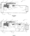
- the figure 3 illustrates, schematically and without limitation, a cooling system according to a second embodiment of the invention.
- the cooling system 1 comprises a cooling circuit in which a cooling fluid circulates.
- the circulation of the coolant is illustrated by black arrows.
- the cooling circuit comprises a cooling pump 2.
- the cooling pump 2 is connected to heat exchangers connected to the internal combustion engine 3, to the lubrication circuit 4, and to the exhaust gas 5, via a pipe 10.
- These heat exchangers of the internal combustion engine 3 and the lubrication circuit 4 are arranged in the cooling circuit in parallel, and this assembly is arranged in series with the heat exchanger with the exhaust gas 5, via a pipe 11.
- the pipe 12 is connected to a first thermostat 6.
- the output 17 of the first thermostat 6 is connected to a heater 8 by means of a pipe 13.
- the fluid leaving the heater 8 flows to the pump 2.
- the outlet 17 is the output of the first thermostat 6 always connected to the input of the first thermostat 6.
- the outlet 18 of the first thermostat 6 is connected to an evaporator 19 by means of a pipe 15.
- the outlet 18 is connected to the inlet of the first thermostat 6 only when the cooling fluid at the inlet of the first thermostat 6 has a temperature higher than or equal to the temperature threshold of the first thermostat 6.
- the cooling fluid is directed into a second thermostat 20 by means of a pipe 31.
- the output 28 of the second thermostat 20 is connected to the pump 2 via a pipe 24 and a pipe 16.
- the outlet 28 is the output of the second thermostat 20 always connected to the input of the second thermostat 20.
- the outlet 27 of the second thermostat 20 is connected to a radiator 7 of the cooling circuit by means of a pipe 21.
- the radiator 7 outlet is connected to the cooling pump 2 via the pipe 16.
- the cooling circuit comprises three branches at the output of the heat exchangers with the elements or equipment of the engine: it is the branch with the heater 8 at the output of the first thermostat 6, the branch back to the pump 2 at the output of the second thermostat 20, and the branch with the radiator 7 at the output of the second thermostat 20.
- the cooling system 1 further comprises a closed circuit according to a Rankine cycle, in which circulates a working fluid.
- the circulation of the working fluid is illustrated by arrows in light gray.
- the closed circuit according to the Rankine cycle comprises a pump of the Rankine circuit 25.
- the Rankine circuit pump 25 is connected to the evaporator 19 by means of a line 32.
- the fluid of cooling and the working fluid exchange heat, thereby cooling the coolant and heating the working fluid.
- the outlet of the evaporator 19 is connected to a turbine 26 via a pipe 33.
- the turbine 26 converts the heat into mechanical or electrical energy.
- the outlet of the turbine 26 is connected to a condenser of the Rankine circuit 29 via a pipe 34.
- the working fluid circulates, in liquid form, to the pump of the Rankine circuit 25. by means of a pipe 35.
- the condenser of the Rankine circuit 29 exchanges heat with a low temperature loop, in which a fluid flows at low temperature.
- the low temperature fluid circulation is illustrated by dark gray arrows.
- the low temperature fluid circulates, by means of lines 36 and 37, between the condenser of the Rankine circuit 29, in which it recovers heat, and a low-temperature radiator 30, in which it is cooled.
- the low-temperature radiator 30 is disposed near the cooling radiator 7.
- an additional condenser 23 for example an air-conditioning condenser, is interposed between the radiator of the low-temperature circuit 30 and the cooling radiator 7.
- the invention relates to a vehicle comprising an internal combustion engine and a cooling device according to one of the variants or one of the combinations of variants described above.
- the vehicle may be in particular a motor vehicle or a heavy goods vehicle.
- the internal combustion engine according to the invention can be used in the field of embedded applications, such as road, maritime or aeronautical, or in the field of stationary installations, such as a generator.
Landscapes
- Engineering & Computer Science (AREA)
- Mechanical Engineering (AREA)
- General Engineering & Computer Science (AREA)
- Chemical & Material Sciences (AREA)
- Combustion & Propulsion (AREA)
- Physics & Mathematics (AREA)
- Thermal Sciences (AREA)
- Engine Equipment That Uses Special Cycles (AREA)
Applications Claiming Priority (1)
| Application Number | Priority Date | Filing Date | Title |
|---|---|---|---|
| FR1853874A FR3080887B1 (fr) | 2018-05-04 | 2018-05-04 | Systeme de refroidissement d'un moteur avec deux thermostats et integrant un circuit selon un cycle de rankine |
Publications (2)
| Publication Number | Publication Date |
|---|---|
| EP3564504A1 true EP3564504A1 (de) | 2019-11-06 |
| EP3564504B1 EP3564504B1 (de) | 2023-09-06 |
Family
ID=62597778
Family Applications (1)
| Application Number | Title | Priority Date | Filing Date |
|---|---|---|---|
| EP19168126.1A Active EP3564504B1 (de) | 2018-05-04 | 2019-04-09 | Kühlsystem eines verbrennungsmotors mit zwei thermostaten und mit einem rankine kreislauf |
Country Status (6)
| Country | Link |
|---|---|
| US (1) | US11008928B2 (de) |
| EP (1) | EP3564504B1 (de) |
| JP (1) | JP2019194476A (de) |
| KR (1) | KR20190127562A (de) |
| CN (1) | CN110439666B (de) |
| FR (1) | FR3080887B1 (de) |
Families Citing this family (5)
| Publication number | Priority date | Publication date | Assignee | Title |
|---|---|---|---|---|
| US11143093B2 (en) * | 2020-01-06 | 2021-10-12 | Power Solutions International, Inc. | Fluid-cooled manifolds and engine systems |
| US11792955B2 (en) * | 2020-04-15 | 2023-10-17 | Baidu Usa Llc | Thermal transfer system and control in multiple operating conditions |
| AT525276B1 (de) | 2021-12-07 | 2023-02-15 | Avl List Gmbh | Verfahren zur temperierung zumindest zweier bauteilanordnungen |
| KR20240000004A (ko) * | 2022-06-21 | 2024-01-02 | 한국자동차연구원 | 하이브리드 차량용 배터리 열관리 시스템 |
| KR20230174788A (ko) * | 2022-06-21 | 2023-12-29 | 한국자동차연구원 | 하이브리드 차량용 배터리 열관리 시스템 |
Citations (5)
| Publication number | Priority date | Publication date | Assignee | Title |
|---|---|---|---|---|
| EP1925806A2 (de) * | 2006-11-24 | 2008-05-28 | Behr GmbH & Co. KG | System mit einem Organic-Rankine-Kreislauf zum Antrieb zumindest einer Expansionsmaschine, Wärmetauscher zum Antrieb einer Expansionsmaschine, Verfahren zum Betreiben zumindest einer Expansionsmaschine |
| EP2320058A1 (de) * | 2008-08-26 | 2011-05-11 | Sanden Corporation | Abwärme nutzende vorrichtung für einen verbrennungsmotor |
| WO2014103820A1 (ja) * | 2012-12-27 | 2014-07-03 | 日産自動車株式会社 | エンジンの廃熱利用装置 |
| WO2016069455A1 (en) * | 2014-10-27 | 2016-05-06 | Cummins, Inc. | System and method of low grade heat utilization for a waste heat recovery system |
| EP3064734A1 (de) * | 2013-10-30 | 2016-09-07 | Isuzu Motors Limited | Motorkühlungssystem |
Family Cites Families (8)
| Publication number | Priority date | Publication date | Assignee | Title |
|---|---|---|---|---|
| JP2005214064A (ja) * | 2004-01-29 | 2005-08-11 | Aisin Seiki Co Ltd | 内燃機関の冷却装置 |
| CN102305151A (zh) * | 2011-08-03 | 2012-01-04 | 天津大学 | 一种高效的内燃机余热能回收系统 |
| JP2014070632A (ja) * | 2012-10-02 | 2014-04-21 | Daimler Ag | 車両用廃熱回収システム |
| FR3002285B1 (fr) * | 2013-02-20 | 2015-02-20 | Renault Sa | Systeme de recuperation de chaleur des gaz d'echappement dans un moteur a combustion interne, avec deux echangeurs de chaleur au niveau d'un circuit de recirculation de gaz |
| DE102014007303A1 (de) * | 2014-05-17 | 2015-11-19 | Man Truck & Bus Ag | Steuer- oder Regelverfahren für ein Kraftfahrzeug |
| JP2017125430A (ja) * | 2016-01-13 | 2017-07-20 | 日野自動車株式会社 | 車両の水冷構造 |
| CN205591989U (zh) * | 2016-04-21 | 2016-09-21 | 兰州理工大学 | 基于有机朗肯循环车用发电系统的冷却结构 |
| JP2018021485A (ja) * | 2016-08-02 | 2018-02-08 | いすゞ自動車株式会社 | 多段ランキンサイクルシステム、内燃機関、及び多段ランキンサイクルシステムの運転方法 |
-
2018
- 2018-05-04 FR FR1853874A patent/FR3080887B1/fr active Active
-
2019
- 2019-04-09 EP EP19168126.1A patent/EP3564504B1/de active Active
- 2019-04-30 KR KR1020190050339A patent/KR20190127562A/ko not_active Application Discontinuation
- 2019-04-30 CN CN201910360014.7A patent/CN110439666B/zh active Active
- 2019-05-02 US US16/401,144 patent/US11008928B2/en active Active
- 2019-05-07 JP JP2019087454A patent/JP2019194476A/ja active Pending
Patent Citations (5)
| Publication number | Priority date | Publication date | Assignee | Title |
|---|---|---|---|---|
| EP1925806A2 (de) * | 2006-11-24 | 2008-05-28 | Behr GmbH & Co. KG | System mit einem Organic-Rankine-Kreislauf zum Antrieb zumindest einer Expansionsmaschine, Wärmetauscher zum Antrieb einer Expansionsmaschine, Verfahren zum Betreiben zumindest einer Expansionsmaschine |
| EP2320058A1 (de) * | 2008-08-26 | 2011-05-11 | Sanden Corporation | Abwärme nutzende vorrichtung für einen verbrennungsmotor |
| WO2014103820A1 (ja) * | 2012-12-27 | 2014-07-03 | 日産自動車株式会社 | エンジンの廃熱利用装置 |
| EP3064734A1 (de) * | 2013-10-30 | 2016-09-07 | Isuzu Motors Limited | Motorkühlungssystem |
| WO2016069455A1 (en) * | 2014-10-27 | 2016-05-06 | Cummins, Inc. | System and method of low grade heat utilization for a waste heat recovery system |
Also Published As
| Publication number | Publication date |
|---|---|
| US11008928B2 (en) | 2021-05-18 |
| US20190338693A1 (en) | 2019-11-07 |
| FR3080887B1 (fr) | 2021-07-30 |
| CN110439666A (zh) | 2019-11-12 |
| FR3080887A1 (fr) | 2019-11-08 |
| KR20190127562A (ko) | 2019-11-13 |
| EP3564504B1 (de) | 2023-09-06 |
| JP2019194476A (ja) | 2019-11-07 |
| CN110439666B (zh) | 2022-07-08 |
Similar Documents
| Publication | Publication Date | Title |
|---|---|---|
| EP3564504B1 (de) | Kühlsystem eines verbrennungsmotors mit zwei thermostaten und mit einem rankine kreislauf | |
| AU2010224799B2 (en) | Method and apparatus for oiling rotating or oscillating components | |
| US20130283790A1 (en) | Device and method for the recovery of waste heat from an internal combustion engine | |
| US20190249589A1 (en) | Waste heat recovery vehicle cooling optimization | |
| FR2885169A1 (fr) | Systeme de gestion de l'energie calorifique a bord d'un vehicule comportant un circuit a cycle de rankine | |
| FR2835884A1 (fr) | Procede de controle de la temperature de gaz admis dans un moteur de vehicule automobile, echangeur et dispositif de gestion de la temperature de ces gaz | |
| FR3002285A1 (fr) | Systeme de recuperation de chaleur des gaz d'echappement dans un moteur a combustion interne, avec deux echangeurs de chaleur au niveau d'un circuit de recirculation de gaz | |
| EA019697B1 (ru) | Установка для охлаждения двигателя | |
| FR2884556A1 (fr) | Dispositif de recuperation d'energie d'un moteur a combustion interne | |
| EP2935853B1 (de) | Luft-/wärmeverwaltung eines motoreinlasses sowie zugehöriges wärmeverwaltungsverfahren | |
| WO2009068504A1 (de) | Aluminiumband für lithografische druckplattenträger und dessen herstellung | |
| FR2832186A1 (fr) | Systeme de gestion de l'energie thermique d'un moteur thermique comprenant deux reseaux | |
| EP2959121B1 (de) | System zur rückgewinnung von wärme aus den abgasen einer brennkraftmaschine | |
| EP3676516B1 (de) | Kühlkreislaufanordnung für eine wärmekraftmaschine und ein getriebe | |
| EP1963657A1 (de) | Vorrichtung zur kühlung von einlassluft und rückgeführter abgase | |
| EP2039906B1 (de) | Verfahren zur Temperaturregelung eines Verbrennungsmotors mit Turbolader und Ladeluftkühler | |
| FR2897392A1 (fr) | Dispositif et procede de refroidissement pour moteur et organe de vehicule. | |
| EP2483092A1 (de) | System und verfahren zur überwachung der temperatur des passagierabteils eines kraftfahrzeugs | |
| EP4189218A1 (de) | Axialturbine mit organischem rankine-zyklus und gesteuertem variablem einlass | |
| FR3061870B1 (fr) | Circuit thermodynamique pour vehicule automobile | |
| WO2021069244A1 (fr) | Systeme de refroidissement a radiateur unique | |
| FR3057299A1 (fr) | Ensemble de motorisation a boucle de rankine | |
| EP1819910B1 (de) | Niedrigtemperatur-ausrüstungskühlsystem für einen teil einer motorfahrzeugausrüstung und damit verbundene wärmetauscher | |
| FR3057305A1 (fr) | Ensemble de motorisation a boucle de rankine | |
| FR3049656A1 (fr) | Systeme de gestion d'air d'admission pour un moteur thermique de vehicule automobile |
Legal Events
| Date | Code | Title | Description |
|---|---|---|---|
| PUAI | Public reference made under article 153(3) epc to a published international application that has entered the european phase |
Free format text: ORIGINAL CODE: 0009012 |
|
| STAA | Information on the status of an ep patent application or granted ep patent |
Free format text: STATUS: THE APPLICATION HAS BEEN PUBLISHED |
|
| AK | Designated contracting states |
Kind code of ref document: A1 Designated state(s): AL AT BE BG CH CY CZ DE DK EE ES FI FR GB GR HR HU IE IS IT LI LT LU LV MC MK MT NL NO PL PT RO RS SE SI SK SM TR |
|
| AX | Request for extension of the european patent |
Extension state: BA ME |
|
| STAA | Information on the status of an ep patent application or granted ep patent |
Free format text: STATUS: REQUEST FOR EXAMINATION WAS MADE |
|
| 17P | Request for examination filed |
Effective date: 20200506 |
|
| RBV | Designated contracting states (corrected) |
Designated state(s): AL AT BE BG CH CY CZ DE DK EE ES FI FR GB GR HR HU IE IS IT LI LT LU LV MC MK MT NL NO PL PT RO RS SE SI SK SM TR |
|
| STAA | Information on the status of an ep patent application or granted ep patent |
Free format text: STATUS: EXAMINATION IS IN PROGRESS |
|
| 17Q | First examination report despatched |
Effective date: 20210806 |
|
| RIC1 | Information provided on ipc code assigned before grant |
Ipc: F02G 5/04 20060101ALN20230303BHEP Ipc: F02G 5/00 20060101ALI20230303BHEP Ipc: F01P 7/16 20060101AFI20230303BHEP |
|
| GRAP | Despatch of communication of intention to grant a patent |
Free format text: ORIGINAL CODE: EPIDOSNIGR1 |
|
| STAA | Information on the status of an ep patent application or granted ep patent |
Free format text: STATUS: GRANT OF PATENT IS INTENDED |
|
| INTG | Intention to grant announced |
Effective date: 20230414 |
|
| GRAS | Grant fee paid |
Free format text: ORIGINAL CODE: EPIDOSNIGR3 |
|
| GRAA | (expected) grant |
Free format text: ORIGINAL CODE: 0009210 |
|
| STAA | Information on the status of an ep patent application or granted ep patent |
Free format text: STATUS: THE PATENT HAS BEEN GRANTED |
|
| AK | Designated contracting states |
Kind code of ref document: B1 Designated state(s): AL AT BE BG CH CY CZ DE DK EE ES FI FR GB GR HR HU IE IS IT LI LT LU LV MC MK MT NL NO PL PT RO RS SE SI SK SM TR |
|
| REG | Reference to a national code |
Ref country code: GB Ref legal event code: FG4D Free format text: NOT ENGLISH |
|
| REG | Reference to a national code |
Ref country code: CH Ref legal event code: EP |
|
| REG | Reference to a national code |
Ref country code: DE Ref legal event code: R096 Ref document number: 602019036578 Country of ref document: DE |
|
| REG | Reference to a national code |
Ref country code: IE Ref legal event code: FG4D Free format text: LANGUAGE OF EP DOCUMENT: FRENCH |
|
| REG | Reference to a national code |
Ref country code: LT Ref legal event code: MG9D |
|
| REG | Reference to a national code |
Ref country code: NL Ref legal event code: MP Effective date: 20230906 |
|
| PG25 | Lapsed in a contracting state [announced via postgrant information from national office to epo] |
Ref country code: GR Free format text: LAPSE BECAUSE OF FAILURE TO SUBMIT A TRANSLATION OF THE DESCRIPTION OR TO PAY THE FEE WITHIN THE PRESCRIBED TIME-LIMIT Effective date: 20231207 |
|
| PG25 | Lapsed in a contracting state [announced via postgrant information from national office to epo] |
Ref country code: SE Free format text: LAPSE BECAUSE OF FAILURE TO SUBMIT A TRANSLATION OF THE DESCRIPTION OR TO PAY THE FEE WITHIN THE PRESCRIBED TIME-LIMIT Effective date: 20230906 Ref country code: RS Free format text: LAPSE BECAUSE OF FAILURE TO SUBMIT A TRANSLATION OF THE DESCRIPTION OR TO PAY THE FEE WITHIN THE PRESCRIBED TIME-LIMIT Effective date: 20230906 Ref country code: NO Free format text: LAPSE BECAUSE OF FAILURE TO SUBMIT A TRANSLATION OF THE DESCRIPTION OR TO PAY THE FEE WITHIN THE PRESCRIBED TIME-LIMIT Effective date: 20231206 Ref country code: LV Free format text: LAPSE BECAUSE OF FAILURE TO SUBMIT A TRANSLATION OF THE DESCRIPTION OR TO PAY THE FEE WITHIN THE PRESCRIBED TIME-LIMIT Effective date: 20230906 Ref country code: LT Free format text: LAPSE BECAUSE OF FAILURE TO SUBMIT A TRANSLATION OF THE DESCRIPTION OR TO PAY THE FEE WITHIN THE PRESCRIBED TIME-LIMIT Effective date: 20230906 Ref country code: HR Free format text: LAPSE BECAUSE OF FAILURE TO SUBMIT A TRANSLATION OF THE DESCRIPTION OR TO PAY THE FEE WITHIN THE PRESCRIBED TIME-LIMIT Effective date: 20230906 Ref country code: GR Free format text: LAPSE BECAUSE OF FAILURE TO SUBMIT A TRANSLATION OF THE DESCRIPTION OR TO PAY THE FEE WITHIN THE PRESCRIBED TIME-LIMIT Effective date: 20231207 Ref country code: FI Free format text: LAPSE BECAUSE OF FAILURE TO SUBMIT A TRANSLATION OF THE DESCRIPTION OR TO PAY THE FEE WITHIN THE PRESCRIBED TIME-LIMIT Effective date: 20230906 |
|
| REG | Reference to a national code |
Ref country code: AT Ref legal event code: MK05 Ref document number: 1608834 Country of ref document: AT Kind code of ref document: T Effective date: 20230906 |
|
| PG25 | Lapsed in a contracting state [announced via postgrant information from national office to epo] |
Ref country code: NL Free format text: LAPSE BECAUSE OF FAILURE TO SUBMIT A TRANSLATION OF THE DESCRIPTION OR TO PAY THE FEE WITHIN THE PRESCRIBED TIME-LIMIT Effective date: 20230906 |
|
| PG25 | Lapsed in a contracting state [announced via postgrant information from national office to epo] |
Ref country code: IS Free format text: LAPSE BECAUSE OF FAILURE TO SUBMIT A TRANSLATION OF THE DESCRIPTION OR TO PAY THE FEE WITHIN THE PRESCRIBED TIME-LIMIT Effective date: 20240106 |
|
| PG25 | Lapsed in a contracting state [announced via postgrant information from national office to epo] |
Ref country code: AT Free format text: LAPSE BECAUSE OF FAILURE TO SUBMIT A TRANSLATION OF THE DESCRIPTION OR TO PAY THE FEE WITHIN THE PRESCRIBED TIME-LIMIT Effective date: 20230906 |
|
| PG25 | Lapsed in a contracting state [announced via postgrant information from national office to epo] |
Ref country code: ES Free format text: LAPSE BECAUSE OF FAILURE TO SUBMIT A TRANSLATION OF THE DESCRIPTION OR TO PAY THE FEE WITHIN THE PRESCRIBED TIME-LIMIT Effective date: 20230906 |
|
| PG25 | Lapsed in a contracting state [announced via postgrant information from national office to epo] |
Ref country code: SM Free format text: LAPSE BECAUSE OF FAILURE TO SUBMIT A TRANSLATION OF THE DESCRIPTION OR TO PAY THE FEE WITHIN THE PRESCRIBED TIME-LIMIT Effective date: 20230906 Ref country code: RO Free format text: LAPSE BECAUSE OF FAILURE TO SUBMIT A TRANSLATION OF THE DESCRIPTION OR TO PAY THE FEE WITHIN THE PRESCRIBED TIME-LIMIT Effective date: 20230906 Ref country code: IS Free format text: LAPSE BECAUSE OF FAILURE TO SUBMIT A TRANSLATION OF THE DESCRIPTION OR TO PAY THE FEE WITHIN THE PRESCRIBED TIME-LIMIT Effective date: 20240106 Ref country code: ES Free format text: LAPSE BECAUSE OF FAILURE TO SUBMIT A TRANSLATION OF THE DESCRIPTION OR TO PAY THE FEE WITHIN THE PRESCRIBED TIME-LIMIT Effective date: 20230906 Ref country code: EE Free format text: LAPSE BECAUSE OF FAILURE TO SUBMIT A TRANSLATION OF THE DESCRIPTION OR TO PAY THE FEE WITHIN THE PRESCRIBED TIME-LIMIT Effective date: 20230906 Ref country code: CZ Free format text: LAPSE BECAUSE OF FAILURE TO SUBMIT A TRANSLATION OF THE DESCRIPTION OR TO PAY THE FEE WITHIN THE PRESCRIBED TIME-LIMIT Effective date: 20230906 Ref country code: AT Free format text: LAPSE BECAUSE OF FAILURE TO SUBMIT A TRANSLATION OF THE DESCRIPTION OR TO PAY THE FEE WITHIN THE PRESCRIBED TIME-LIMIT Effective date: 20230906 Ref country code: SK Free format text: LAPSE BECAUSE OF FAILURE TO SUBMIT A TRANSLATION OF THE DESCRIPTION OR TO PAY THE FEE WITHIN THE PRESCRIBED TIME-LIMIT Effective date: 20230906 Ref country code: PT Free format text: LAPSE BECAUSE OF FAILURE TO SUBMIT A TRANSLATION OF THE DESCRIPTION OR TO PAY THE FEE WITHIN THE PRESCRIBED TIME-LIMIT Effective date: 20240108 |