EP3564065B1 - Segment de piste isolante pour un système d'alimentation par le sol et système d'alimentation par le sol correspondant - Google Patents
Segment de piste isolante pour un système d'alimentation par le sol et système d'alimentation par le sol correspondant Download PDFInfo
- Publication number
- EP3564065B1 EP3564065B1 EP19172456.6A EP19172456A EP3564065B1 EP 3564065 B1 EP3564065 B1 EP 3564065B1 EP 19172456 A EP19172456 A EP 19172456A EP 3564065 B1 EP3564065 B1 EP 3564065B1
- Authority
- EP
- European Patent Office
- Prior art keywords
- power supply
- supply system
- track
- insulating
- segment
- Prior art date
- Legal status (The legal status is an assumption and is not a legal conclusion. Google has not performed a legal analysis and makes no representation as to the accuracy of the status listed.)
- Active
Links
Images

Classifications
-
- B—PERFORMING OPERATIONS; TRANSPORTING
- B60—VEHICLES IN GENERAL
- B60M—POWER SUPPLY LINES, AND DEVICES ALONG RAILS, FOR ELECTRICALLY- PROPELLED VEHICLES
- B60M1/00—Power supply lines for contact with collector on vehicle
- B60M1/30—Power rails
-
- B—PERFORMING OPERATIONS; TRANSPORTING
- B60—VEHICLES IN GENERAL
- B60M—POWER SUPPLY LINES, AND DEVICES ALONG RAILS, FOR ELECTRICALLY- PROPELLED VEHICLES
- B60M5/00—Arrangements along running rails or at joints thereof for current conduction or insulation, e.g. safety devices for reducing earth currents
-
- B—PERFORMING OPERATIONS; TRANSPORTING
- B60—VEHICLES IN GENERAL
- B60L—PROPULSION OF ELECTRICALLY-PROPELLED VEHICLES; SUPPLYING ELECTRIC POWER FOR AUXILIARY EQUIPMENT OF ELECTRICALLY-PROPELLED VEHICLES; ELECTRODYNAMIC BRAKE SYSTEMS FOR VEHICLES IN GENERAL; MAGNETIC SUSPENSION OR LEVITATION FOR VEHICLES; MONITORING OPERATING VARIABLES OF ELECTRICALLY-PROPELLED VEHICLES; ELECTRIC SAFETY DEVICES FOR ELECTRICALLY-PROPELLED VEHICLES
- B60L5/00—Current collectors for power supply lines of electrically-propelled vehicles
- B60L5/42—Current collectors for power supply lines of electrically-propelled vehicles for collecting current from individual contact pieces connected to the power supply line
-
- B—PERFORMING OPERATIONS; TRANSPORTING
- B60—VEHICLES IN GENERAL
- B60M—POWER SUPPLY LINES, AND DEVICES ALONG RAILS, FOR ELECTRICALLY- PROPELLED VEHICLES
- B60M1/00—Power supply lines for contact with collector on vehicle
- B60M1/30—Power rails
- B60M1/34—Power rails in slotted conduits
-
- H—ELECTRICITY
- H01—ELECTRIC ELEMENTS
- H01B—CABLES; CONDUCTORS; INSULATORS; SELECTION OF MATERIALS FOR THEIR CONDUCTIVE, INSULATING OR DIELECTRIC PROPERTIES
- H01B17/00—Insulators or insulating bodies characterised by their form
- H01B17/14—Supporting insulators
-
- H—ELECTRICITY
- H02—GENERATION; CONVERSION OR DISTRIBUTION OF ELECTRIC POWER
- H02G—INSTALLATION OF ELECTRIC CABLES OR LINES, OR OF COMBINED OPTICAL AND ELECTRIC CABLES OR LINES
- H02G9/00—Installations of electric cables or lines in or on the ground or water
- H02G9/02—Installations of electric cables or lines in or on the ground or water laid directly in or on the ground, river-bed or sea-bottom; Coverings therefor, e.g. tile
-
- B—PERFORMING OPERATIONS; TRANSPORTING
- B60—VEHICLES IN GENERAL
- B60M—POWER SUPPLY LINES, AND DEVICES ALONG RAILS, FOR ELECTRICALLY- PROPELLED VEHICLES
- B60M1/00—Power supply lines for contact with collector on vehicle
- B60M1/12—Trolley lines; Accessories therefor
- B60M1/18—Section insulators; Section switches
-
- B—PERFORMING OPERATIONS; TRANSPORTING
- B60—VEHICLES IN GENERAL
- B60M—POWER SUPPLY LINES, AND DEVICES ALONG RAILS, FOR ELECTRICALLY- PROPELLED VEHICLES
- B60M1/00—Power supply lines for contact with collector on vehicle
- B60M1/30—Power rails
- B60M1/34—Power rails in slotted conduits
- B60M1/346—Joints
Definitions
- the field of the invention is that of ground feed systems.
- the patent FR3017342 describes a ground feed system for a railway vehicle, comprising a conductive track held by a track support on a concrete base.
- the ground feed system is buried in the roadway so that the conductive track is flush with the road surface or protrudes slightly a few centimeters above the road surface.
- the conductive track is subdivided into a plurality of segments, which are installed one after the other on the track support in the direction of the railway track.
- the document EP 2907690 discloses a possible track support taking the form of an elastomeric material slipper suitable for receiving the components of the conductive track and being fixed in a concrete base of the track.
- a railway vehicle such as a tram
- a railway vehicle is equipped with two runners which are lowered so as to come into sliding contact on the conductive track.
- the segments of the track are individually supplied with electrical power as the tram passes by so as to provide it with the power necessary for its movement.
- An evolution of a catenary-free power system consists in combining the ground-based power supply solution with an on-board energy solution thus allowing the tram to have a certain autonomy.
- the tram recharges its on-board energy source when it is in a zone of the track supplied by the ground (also called an equipped zone).
- the areas of the track crossed independently are devoid of any equipment belonging to the power supply system (also called unequipped zone).
- the tram is stopped before entering the road. unequipped area; each pad is raised so as to leave contact with the conductive track; once the runners are raised, the tram independently crosses the unequipped area; once above a new equipped zone, the tram is stopped again; the pads are lowered to come into contact with the conductive track; and finally the tram can start again.
- the object of the invention is therefore to respond to this drawback by proposing an improved ground feed system.
- the invention relates to an insulating track segment and a ground feed system according to the appended claims.
- the figure 1 represents the intersection 12 between a railway line 1 and a road 2.
- the railway line comprises two son of rails 13 and 14 running in parallel with one another, in a longitudinal direction Z of the railway line 1.
- Route 2 runs in a Y direction, orthogonal to the railway track 1.
- the vertical direction corresponds to the X direction.
- Track 1 is equipped with a power supply system from the ground 10 to allow the circulation of a railway vehicle (not shown in the figures), in particular a tram, by supplying it with the electrical energy it needs.
- the system 10 notably comprises a conductive track 30 supplied with electrical power by suitable means.
- the conductive track 30 is flush with the surface of the roadway 6.
- Each pad with which the tram is fitted slides on the upper surface of the conductive track 30 so as to collect the electric power delivered by the system 10.
- the conductive track 30 is held in position by a track support 34, which itself is anchored in a concrete base 23, cast at the bottom of a trench made in the surface of the roadway 6.
- the track support 34 is made of an elastomeric material, the upper face of which has a receiving groove for the conductive track 30 and the lower face of which has a V-concave shape so as to be received in a mating shape reserved in the upper part of the raft 23.
- a track support consisting of a section fixed to the concrete base. This profile comprises, on its upper face, a groove for receiving the conductive track.
- the conductive track is interrupted. It therefore has a section of conductive track 30 upstream of the intersection 12 and a section of conductive track 30 'downstream of the intersection 12. The downstream section is held by a support 34' anchored to a concrete base 23 '. . Intersection 12 is therefore an unequipped zone.
- the system 10 comprises an insulating track 40 extending between the sections of conductive track 30 and 30 ', so to ensure surface continuity for the tram runner (s).
- the insulating track 40 is implanted so that the upper surface of the insulating track 40 is at the same level as the upper surface of the conductive track sections 30 and 30 ', at least at the level of the ends of the conductive track sections.
- the insulating track 40 consists of a plurality of insulating track segments 42.
- the segments 42 are arranged one after the other in the Z direction.
- Each segment 42 is fixed directly to the surface of the carriageway 6.
- Each segment 42 is thus advantageously received in a suitable groove 44 made in the surface of the roadway 6.
- Each segment of insulating track 42 is fixed by fixing means which will be detailed in figure 2 .
- the asphalt constituting the surface layer of the roadway is brought on either side of the insulating track 40 so that the latter is flush with the surface of the roadway 6 or protrudes a few millimeters above this surface.
- the segments 42 are anchored directly on a flat upper face (or provided with a suitable groove) of the concrete base of the ground supply system.
- the implantation of the insulating track does not require a track support for its fixing.
- an insulating track segment 42 is shown.
- It comprises a body 50 made of a material insulating against electric current, preferably an elastomer, for example an elastomer of the EPDM type (ethylene-propylene-diene monomer).
- an elastomer for example an elastomer of the EPDM type (ethylene-propylene-diene monomer).
- the body 50 has a plurality of blind holes 51. These are arranged so as to form a pattern, for example a die having a plurality of rows and columns extending over the entire upper face of the body 50.
- each blind hole 51 receives an insert 52, preferably of cylindrical shape.
- the insulating track segment described here in detail being short (it has a length less than or equal to 60cm) two blind holes are reserved for fixing. As a variant, in particular for longer segments, a greater number of blind holes can be reserved for fixing.
- Each insert 52 has a diameter slightly greater than that of the blind hole 51 which receives it. The insert is then forcibly inserted into the blind hole and the frictional forces are sufficient for good retention in position. Optionally, the inserts can also be glued.
- Each insert 52 has a height greater than the depth of the blind hole 51 which receives it. Thus the inserts 52 protrude above the upper face of the body 50. The upper face of the inserts 52 thus constitute the upper surface of the insulating track segment 42 against which the tram slider slides.
- the inserts have a diameter of 20 mm and a height of 10 mm.
- the upper edge of each insert is advantageously chamfered to avoid impacts with the wiper.
- the material of the inserts 52 is chosen so as to have a suitable hardness to limit wear and allow the slider to slide, while resisting the passage of road vehicles crossing the intersection 12.
- the inserts 52 are made of ceramic, for example made of 92% alumina, which is the best abrasion resistant electrical insulating material.
- two blind holes 51 ′ are reserved for fixing the insulating track segment 42.
- the fixing means are for example constituted by a screw 54 and an insulating plug, of which a single screw 54 is visible on the figure 2 .
- the elastomeric material of the body 50 of the segment 42 is reinforced by a metal plate 53 extending substantially over the entire length and the width of the segment 42.
- the plate 53 is preferably made of steel. (S235 for example). This metal plate 53 is embedded in the elastomer material constituting the body 50. It is located below the blind holes for receiving the inserts.
- the bottom of the blind hole 51 ' is provided with a through hole passing through the metal plate 53 and the elastomer layers above and below the metal plate 53.
- the through hole opens out on the underside of the body. 50, which also corresponds to the lower surface of the insulating track segment 42.
- the screw 54 is inserted through the through hole in the dowel to anchor itself for example in the concrete of the raft.
- the head of the screw 54 is received entirely inside the corresponding blind hole 51 ′.
- the possibility of fixing the insulating track directly in the roadway or, as a variant, on a concrete base makes it possible to reduce the length of the track d. power supply to be installed.
- the installation site of such a railway line can therefore consist in carrying out the sections upstream and downstream of a section of the track that the tramway will cross independently.
Landscapes
- Engineering & Computer Science (AREA)
- Mechanical Engineering (AREA)
- Power Engineering (AREA)
- Transportation (AREA)
- Road Paving Structures (AREA)
- Current-Collector Devices For Electrically Propelled Vehicles (AREA)
- Control Of Vehicles With Linear Motors And Vehicles That Are Magnetically Levitated (AREA)
Description
- L'invention a pour domaine celui des systèmes d'alimentation par le sol.
- Le brevet
FR3017342 - Le système d'alimentation par le sol est enterré dans la chaussée de manière à ce que la piste conductrice affleure à la surface de la chaussée ou fasse une légère saillie de quelques centimètres au-dessus de la surface de la chaussée.
- La piste conductrice est subdivisée en une pluralité de segments, qui sont installés les uns à la suite des autres sur le support de piste selon la direction de la voie ferrée.
- Entre deux segments successifs de la piste conductrice, est collé, sur le support de piste, un élément isolant pour former une piste conductrice discontinue.
- Le document
EP 2907690 divulgue un support de piste possible prenant la forme d'un chausson en matériau élastomère propre à recevoir les composants de la piste conductrice et être fixé dans un radier en béton de la voie. - Le document "Tramway & Light Rail - WELCOME TO DOSHIN RUBBER", 18 juillet 2017 (2017-07-18), (accessible à l'adresse Internet: httpsj/web.archive.org/web/2017071814291 6/https://doshinrubber.com/tramway-light-rail/) divulgue un tel système d'alimentation par le sol mettant en oeuvre un support de piste similaire à celui divulgué dans le document
EP 2907690 . - Un véhicule ferroviaire, tel qu'un tramway, est équipé de deux patins qui sont descendus de manière à venir en contact glissant sur la piste conductrice. Les segments de la piste sont alimentés individuellement en puissance électrique au passage du tramway de manière à lui fournir la puissance nécessaire à son déplacement.
- Une évolution d'un système d'alimentation sans caténaire consiste à combiner la solution d'alimentation par le sol avec une solution d'énergie embarquée permettant ainsi au tramway d'avoir une certaine autonomie.
- Dans cette solution mixte, qui permet d'optimiser la longueur de piste conductrice à installer, le tramway vient recharger sa source d'énergie embarquée lorsqu'il est sur une zone de la voie alimentée par le sol (aussi dénommée zone équipée).
- Ce faisant, les zones de la voie franchies en autonomie sont dépourvues d'équipement appartenant au système d'alimentation (aussi dénommée zone non-équipée).
- Pour éviter qu'ils ne frottent sur la surface de la chaussée au moment du franchissement par le véhicule ferroviaire d'une zone non-équipée, il est nécessaire de relever les patins selon la procédure suivante : le tramway est arrêté avant de rentrer sur la zone non-équipée ; chaque patin est relevé de manière à quitter le contact avec la piste conductrice ; une fois les patins relevés, le tramway franchit en autonomie la zone non-équipée ; une fois au-dessus d'une nouvelle zone équipée, le tramway est à nouveau arrêté ; les patins sont descendus pour venir en contact de la piste conductrice ; et finalement le tramway peut repartir.
- Il est ainsi nécessaire de procéder au relevage du ou de chaque patin du véhicule électrique car s'il était laissé en position basse il risquerait de frotter sur différents types de revêtement non prévus à cet effet (herbe, béton, asphalte, pavés, etc.) Le patin connaîtrait alors une dégradation accélérée et un vieillissement prématuré.
- L'invention a donc pour but de répondre à cet inconvénient en proposant un système d'alimentation par le sol amélioré.
- Pour cela l'invention a pour objet un segment de piste isolante et un système d'alimentation par le sol selon les revendications annexées.
- L'invention et ses avantages seront mieux compris à la lecture de la description détaillée qui va suivre d'un mode de réalisation particulier, donné uniquement à titre d'exemple non limitatif, cette description étant faite en se référant aux dessins annexés, sur lesquels :
- la
figure 1 est une représentation en perspective éclatée d'un système d'alimentation par le sol selon l'invention implanté au niveau d'une intersection entre une voie ferrée et une route ; et, - la
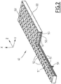
figure 2 est une représentation en perspective d'un segment de piste isolante du système d'alimentation par le sol de lafigure 1 , ce segment étant représenté en coupes verticales partielles. - La
figure 1 représente l'intersection 12 entre une voie ferrée 1 et une route 2. - La voie ferrée comporte deux fils de rails 13 et 14 circulant en parallèle l'un de l'autre, selon une direction longitudinale Z de la voie ferrée 1.
- La route 2 circule selon une direction Y, orthogonale à la voie ferrée 1. La direction verticale correspond à la direction X.
- La voie 1 est équipée d'un système d'alimentation par le sol 10 pour permettre la circulation d'un véhicule ferroviaire (non représenté sur les figures), notamment un tramway, en lui fournissant l'énergie électrique dont il a besoin.
- Le système 10 comporte notamment une piste conductrice 30 alimentée en puissance électrique par des moyens adaptés.
- La piste conductrice 30 affleure à la surface de la chaussée 6.
- Chaque patin dont est équipé le tramway glisse sur la surface supérieure de la piste conductrice 30 de manière à collecter la puissance électrique délivrée par le système 10.
- Dans le mode de réalisation particulier, représenté à la
figure 1 , la piste conductrice 30 est maintenue en position par un support de piste 34, qui lui-même est ancré dans un radier en béton 23, coulé au fond d'une tranchée pratiquée dans la surface de la chaussée 6. - Dans le mode de réalisation particulier représenté à la
figure 1 , le support de piste 34 est réalisé dans un matériau élastomère, dont la face supérieure comporte une rainure de réception de la piste conductrice 30 et dont la face inférieure présente une forme concave en V de manière à être reçue dans une forme conjuguée réservée dans la partie supérieure du radier 23. - Il est à noter que l'on connaît d'autres types de systèmes d'alimentation par le sol qui diffèrent du mode de réalisation de la
figure 1 par un support de piste différent. Par exemple, on connait un support de piste constitué par un profilé fixé sur le radier en béton. Ce profilé comporte, sur sa face supérieure, une rainure de réception de la piste conductrice. - Au niveau de l'intersection 12 proprement dite, la piste conductrice est interrompue. Elle présente donc un tronçon de piste conductrice 30 en amont de l'intersection 12 et un tronçon de piste conductrice 30' en aval de l'intersection 12. Le tronçon aval est maintenu par un support 34' ancré sur un radier en béton 23'. L'intersection 12 est donc une zone non-équipée.
- Selon l'invention, pour éviter d'avoir à relever le ou les patins du tramway au franchissement de l'intersection 12, le système 10 comporte une piste isolante 40 s'étendant entre les tronçons de piste conductrice 30 et 30', de manière à assurer une continuité de surface pour le ou les patins du tramway. La piste isolante 40 est implantée de manière à ce que la surface supérieure de la piste isolante 40 se trouve au même niveau que la surface supérieure des tronçons de piste conductrice 30 et 30', au moins au niveau des extrémités des tronçons de piste conductrice.
- La piste isolante 40 est constituée d'une pluralité de segments de piste isolante 42. Les segments 42 sont disposés les uns à la suite des autres selon la direction Z.
- Chaque segment 42 est fixé directement sur la surface de la chaussée 6.
- Chaque segment 42 est ainsi avantageusement reçu dans une rainure 44 adaptée pratiquée dans la surface de la chaussée 6. Chaque segment de piste isolante 42 est fixé par des moyens de fixation qui seront détaillés à la
figure 2 . L'asphalte constitutif de la couche superficielle de la chaussée est amenée de part et d'autre de la piste isolante 40 de manière à ce que celle-ci soit affleurante à la surface de la chaussée 6 ou fasse saillie de quelques millimètres au-dessus de cette surface. - En variante, les segments 42 sont ancrés directement sur une face supérieure plane (ou munie d'une rainure adaptée) du radier en béton du système d'alimentation par le sol.
- Ainsi, l'implantation de la piste isolante ne requiert pas de support de piste pour sa fixation.
- En se référant à la
figure 2 , un segment de piste isolante 42 est représenté. - Il présente une forme générale parallélépipédique.
- Il comporte un corps 50 réalisé en un matériau isolant du courant électrique, de préférence un élastomère, par exemple un élastomère du type EPDM (éthylène-propylène-diène monomère).
- Le corps 50 comporte une pluralité de trous borgnes 51. Ceux-ci sont disposés de manière à former un motif, par exemple une matrice ayant une pluralité de rangées et de colonnes s'étendant sur toute la face supérieure du corps 50.
- A l'exception de deux trous borgnes 51' qui sont réservés pour la fixation du segment 42, chaque trou borgne 51 reçoit un insert 52, de préférence de forme cylindrique. Le segment de piste isolante décrit ici en détail étant court (il présente une longueur inférieure ou égale à 60cm) deux trous borgnes sont réservés pour la fixation. En variante, notamment pour des segments plus long, un plus grand nombre de trous borgnes peuvent être réservés à la fixation.
- Chaque insert 52 présent un diamètre légèrement supérieur à celui du trou borgne 51 qui le reçoit. L'insert est alors inséré à force dans le trou borgne et les forces de frottement sont suffisantes pour un bon maintien en position. Eventuellement, les inserts peuvent également être collés.
- Chaque insert 52 présente une hauteur supérieure à la profondeur du trou borgne 51 qui le reçoit. Ainsi les inserts 52 font saillie au-dessus de la face supérieure du corps 50. La face supérieure des inserts 52 constituent ainsi la surface supérieure du segment de piste isolante 42 contre laquelle glisse le frotteur du tramway. Par exemple, les inserts ont un diamètre de 20 mm et une hauteur de 10 mm. L'arête supérieure de chaque insert est avantageusement chanfreinée pour éviter les chocs avec le frotteur.
- Le matériau des inserts 52 est choisi de manière à présenter une dureté adaptée pour limiter l'usure et autoriser le glissement du frotteur, tout en résistant au passage des véhicules routiers traversant l'intersection 12. Par exemple, les inserts 52 sont réalisés en céramique, par exemple constituée à 92% d'alumine, qui est le matériau isolant électrique résistant le mieux à l'abrasion.
- Comme représenté sur la
figure 2 , deux trous borgnes 51' sont réservés pour la fixation du segment de piste isolante 42. - Les moyens de fixation sont par exemple constitués par une vis 54 et une cheville isolante, dont une seule vis 54 est visible sur la
figure 2 . - Pour permettre un tel ancrage, le matériau élastomère du corps 50 du segment 42 est renforcé par une plaque métallique 53 s'étendant sensiblement sur l'intégralité de la longueur et de la largeur du segment 42. La plaque 53 est de préférence réalisée en acier (S235 par exemple). Cette plaque métallique 53 est noyée dans le matériau élastomère constitutif du corps 50. Elle est située en dessous des trous borgnes de réception des inserts.
- Le fait que le segment de piste isolante 42 soit renforcé par une plaque métallique 53 améliore sa solidité mécanique et permet une implantation simple dans la chaussée.
- Le fond du trou borgne 51' est muni d'un trou traversant passant à travers la plaque métallique 53 et les couches d'élastomère au-dessus et en-dessous de la plaque métallique 53. Le trou traversant débouche sur la face inférieure du corps 50, qui correspond également à la surface inférieure du segment de piste isolante 42.
- La vis 54 est insérée à travers le trou traversant dans la cheville pour venir s'ancrer par exemple dans le béton du radier. La tête de la vis 54 est reçue intégralement à l'intérieur du trou borgne 51' correspondant.
- L'homme du métier constatera que l'utilisation d'une piste isolante pour rabouter deux tronçons de piste conductrice permet d'assurer une continuité de surface propice au glissement du frotteur dont est équipé le véhicule électrique. Il n'y a donc plus besoin de mettre en œuvre la procédure complexe de relevage du frotteur au moment du franchissement d'une intersection équipée du système selon l'invention.
- De plus, la possibilité de fixer directement la piste isolante dans la chaussée ou, en variante, sur un radier en béton (ayant une face supérieure plane ou munie d'une rainure présentant un profil simple), permet de réduire la longueur de piste d'alimentation à installer.
- Le chantier d'installation d'une telle voie ferrée peut donc consister à réaliser les tronçons en amont et en aval d'une section de la voie que le tramway franchira en autonomie.
Claims (7)
- Segment de piste isolante (42) pour un système d'alimentation par le sol (10), ledit segment de piste isolante (42) comportant un corps (50) réalisé en un matériau isolant du courant électrique, ledit segment de piste isolante (42) constituant une portion d'une piste isolante (40) destinée à former, avec une piste conductrice du système d'alimentation par le sol, une surface de glissement continue pour un patin d'un véhicule alimenté par ledit système d'alimentation par le sol,caractérisé en ce que le corps (50) est réalisé en un matériau élastomère et intègre une plaque métallique (53) de renfort du corps (50),en ce que le corps (50) est muni d'une pluralité d'inserts (52) qui définissent la surface de glissement dudit segment de piste isolante,et en ce que la plaque métallique (53) est noyée dans le matériau élastomère constitutif du corps (50) et est située en dessous de trous borgnes (51) de réception des inserts (52).
- Segment selon la revendication 1, dans lequel matériau élastomère est un élastomère du type éthylène-propylène-diène monomère - EPDM.
- Segment selon la revendication 1 ou la revendication 2, dans lequel les inserts (52) sont réalisés en céramique.
- Segment selon l'une quelconque des revendications 1 à 3, dans lequel le segment de piste isolante (42) comporte un trou traversant propre à recevoir un système de fixation adapté (54).
- Système d'alimentation par le sol (10), caractérisé en ce qu'il comporte au moins un segment de piste isolante (42) selon l'une quelconque des revendications 1 à 4.
- Système d'alimentation par le sol selon la revendication 5, dans lequel le segment de piste isolante (42) est ancré directement dans un radier en béton enterré dans la chaussée.
- Système d'alimentation par le sol selon la revendication 5, dans lequel le segment de piste isolante (42) est ancré directement dans la chaussée.
Applications Claiming Priority (1)
| Application Number | Priority Date | Filing Date | Title |
|---|---|---|---|
| FR1853864A FR3080803B1 (fr) | 2018-05-04 | 2018-05-04 | Segment de piste isolante pour un systeme d'alimentation par le sol et systeme d'alimentation par le sol correspondant |
Publications (2)
| Publication Number | Publication Date |
|---|---|
| EP3564065A1 EP3564065A1 (fr) | 2019-11-06 |
| EP3564065B1 true EP3564065B1 (fr) | 2021-12-15 |
Family
ID=62528738
Family Applications (1)
| Application Number | Title | Priority Date | Filing Date |
|---|---|---|---|
| EP19172456.6A Active EP3564065B1 (fr) | 2018-05-04 | 2019-05-03 | Segment de piste isolante pour un système d'alimentation par le sol et système d'alimentation par le sol correspondant |
Country Status (9)
| Country | Link |
|---|---|
| US (1) | US10974618B2 (fr) |
| EP (1) | EP3564065B1 (fr) |
| AU (1) | AU2019203080B2 (fr) |
| CA (1) | CA3041706A1 (fr) |
| CO (1) | CO2019004534A1 (fr) |
| ES (1) | ES2907831T3 (fr) |
| FR (1) | FR3080803B1 (fr) |
| IL (1) | IL266319A (fr) |
| MX (1) | MX2019005105A (fr) |
Families Citing this family (1)
| Publication number | Priority date | Publication date | Assignee | Title |
|---|---|---|---|---|
| CN118219939A (zh) * | 2023-08-04 | 2024-06-21 | 比亚迪股份有限公司 | 导电轨和轨道交通系统 |
Family Cites Families (11)
| Publication number | Priority date | Publication date | Assignee | Title |
|---|---|---|---|---|
| US1964804A (en) * | 1932-09-24 | 1934-07-03 | Norris C Barnard | Railway track crossover |
| US3268170A (en) * | 1964-06-19 | 1966-08-23 | Railroad Rubber Products Inc | Insulating rubber rail seat |
| BE789791A (fr) * | 1971-10-08 | 1973-02-01 | Fischer Ag Georg | Procede et dispositif pour raccorder des conducteurs electriques a des rails de voie de transport |
| US4793545A (en) * | 1987-07-14 | 1988-12-27 | Construction Polymers Company | Embedded track assembly |
| CN100364196C (zh) * | 2000-09-26 | 2008-01-23 | 乔纳森·马克·莫里斯 | 与铁路轨道结合在一起的管道 |
| FR2861102B1 (fr) * | 2003-10-20 | 2006-03-17 | Lohr Ind | Troncon modulaire de voie pour vehicule de transport urbain autoguide sur pneumatiques |
| FR3017342B1 (fr) | 2014-02-10 | 2016-03-18 | Alstom Transport Sa | Support de piste d'un systeme d'alimentation electrique par le sol pour un vehicule terrestre, rail comportant un tel support et procede d'implantation |
| FR3019113B1 (fr) * | 2014-03-25 | 2016-05-06 | Alstom Transp Tech | Systeme d'alimentation par le sol pour vehicules electriques non guides |
| CN104149661A (zh) * | 2014-08-04 | 2014-11-19 | 镇江大全赛雪龙牵引电气有限公司 | 嵌地式供电系统端头连接机构 |
| CN204095572U (zh) * | 2014-08-04 | 2015-01-14 | 镇江大全赛雪龙牵引电气有限公司 | 嵌地式供电系统连接盒 |
| FR3037195B1 (fr) * | 2015-06-08 | 2019-01-25 | Alstom Transport Technologies | Ensemble constitue d'un vehicule electrique et d'un systeme de recharge stationnaire par conduction ; systeme, installation, vehicule et procede associes |
-
2018
- 2018-05-04 FR FR1853864A patent/FR3080803B1/fr not_active Expired - Fee Related
-
2019
- 2019-04-29 IL IL266319A patent/IL266319A/en unknown
- 2019-04-29 CA CA3041706A patent/CA3041706A1/fr active Pending
- 2019-04-30 MX MX2019005105A patent/MX2019005105A/es unknown
- 2019-05-01 AU AU2019203080A patent/AU2019203080B2/en active Active
- 2019-05-02 CO CONC2019/0004534A patent/CO2019004534A1/es unknown
- 2019-05-03 EP EP19172456.6A patent/EP3564065B1/fr active Active
- 2019-05-03 ES ES19172456T patent/ES2907831T3/es active Active
- 2019-05-03 US US16/402,733 patent/US10974618B2/en active Active
Also Published As
| Publication number | Publication date |
|---|---|
| ES2907831T3 (es) | 2022-04-26 |
| BR102019009014A2 (pt) | 2020-04-28 |
| FR3080803A1 (fr) | 2019-11-08 |
| IL266319A (en) | 2019-07-31 |
| EP3564065A1 (fr) | 2019-11-06 |
| US20190337410A1 (en) | 2019-11-07 |
| CA3041706A1 (fr) | 2019-11-04 |
| AU2019203080A1 (en) | 2019-11-21 |
| US10974618B2 (en) | 2021-04-13 |
| AU2019203080B2 (en) | 2023-04-06 |
| FR3080803B1 (fr) | 2021-07-23 |
| CO2019004534A1 (es) | 2020-05-05 |
| MX2019005105A (es) | 2019-11-05 |
Similar Documents
| Publication | Publication Date | Title |
|---|---|---|
| EP2191070B1 (fr) | Module prefabrique de voie pour vehicule de transport urbain autoguide sur pneumatiques | |
| EP1685297B1 (fr) | Troncon modulaire de voie pour vehicule de transport urbain notamment autoguide sur pneumatiques | |
| EP2907690B1 (fr) | Support de piste d'un système d'alimentation électrique par le sol pour un véhicule terrestre, rail comportant un tel support et procédé d'implantation | |
| EP3395606B1 (fr) | Support de pistes conductrices en élastomère à section rectangulaire pour système d'alimentation électrique par le sol | |
| EP3564065B1 (fr) | Segment de piste isolante pour un système d'alimentation par le sol et système d'alimentation par le sol correspondant | |
| FR3019113A1 (fr) | Systeme d'alimentation par le sol pour vehicules electriques non guides | |
| EP0585959B1 (fr) | Conduit enterré | |
| WO2006035139A1 (fr) | Systeme d'alimentation, electrique par le sol pour vehicule electrique | |
| BE1020879A4 (fr) | Coeur a pointe mobile pour rails a ornieres. | |
| EP2195187A1 (fr) | Support transversal lateral repetitif pour au moins un profile d'alimentation laterale electrique et pour le rail de guidage d'un vehicule routier guide a motorisation electrique | |
| FR2982622A1 (fr) | Dalle en beton de support d'au moins deux files de rails d'une voie ferree et voie ferree equipee d'au moins une telle dalle | |
| EP0145609B1 (fr) | Platelage de passage à niveau | |
| EP0952307B1 (fr) | Procédé pour la construction d'un ouvrage sous un talus de support d'une voie ferrée ou d'une chaussée | |
| WO2006042922A1 (fr) | Croisement de deux rails de guidage faisant partie d'un ensemble de captage au sol d'energie electrique pour un vehicule. | |
| FR2901814A1 (fr) | Ensemble pour passage a niveau | |
| FR3131927A1 (fr) | Module de voie ferree | |
| EP2865808A1 (fr) | Voie de roulement continue sur ouvrage viaduc | |
| FR2562922A1 (fr) | Dalle de chaussee, notamment pour des voies de circulation provisoires | |
| FR2610955A1 (fr) | Procede de realisation de voiries a derouler sur le sol et element de chemin de roulement pour sa mise en oeuvre | |
| EP3473491B1 (fr) | Système d'alimentation électrique d'un véhicule par le sol et procédé de renforcement associé | |
| FR3052465A1 (fr) | Systeme d'eclissage pour barres de guidage laterales de vehicule guide de type val, procede d'eclissage | |
| FR2726300A1 (fr) | Ralentisseur routier realise par assemblage d'elements modulaires | |
| FR2938275A1 (fr) | Rampant de quai prefabrique et quai prefabrique pour un arret de vehicule de transport | |
| FR3039173A1 (fr) | Pont pour le passage de troupeaux et procede de montage d’un tel pont | |
| FR3047017A1 (fr) | Module de caniveau pour la realisation d'un caniveau fonctionnalise a proximite d'une voie de circulation |
Legal Events
| Date | Code | Title | Description |
|---|---|---|---|
| PUAI | Public reference made under article 153(3) epc to a published international application that has entered the european phase |
Free format text: ORIGINAL CODE: 0009012 |
|
| STAA | Information on the status of an ep patent application or granted ep patent |
Free format text: STATUS: THE APPLICATION HAS BEEN PUBLISHED |
|
| STAA | Information on the status of an ep patent application or granted ep patent |
Free format text: STATUS: REQUEST FOR EXAMINATION WAS MADE |
|
| AK | Designated contracting states |
Kind code of ref document: A1 Designated state(s): AL AT BE BG CH CY CZ DE DK EE ES FI FR GB GR HR HU IE IS IT LI LT LU LV MC MK MT NL NO PL PT RO RS SE SI SK SM TR |
|
| AX | Request for extension of the european patent |
Extension state: BA ME |
|
| 17P | Request for examination filed |
Effective date: 20191022 |
|
| RBV | Designated contracting states (corrected) |
Designated state(s): AL AT BE BG CH CY CZ DE DK EE ES FI FR GB GR HR HU IE IS IT LI LT LU LV MC MK MT NL NO PL PT RO RS SE SI SK SM TR |
|
| GRAP | Despatch of communication of intention to grant a patent |
Free format text: ORIGINAL CODE: EPIDOSNIGR1 |
|
| STAA | Information on the status of an ep patent application or granted ep patent |
Free format text: STATUS: GRANT OF PATENT IS INTENDED |
|
| INTG | Intention to grant announced |
Effective date: 20210709 |
|
| RIN1 | Information on inventor provided before grant (corrected) |
Inventor name: DUPRAT, PATRICK |
|
| GRAS | Grant fee paid |
Free format text: ORIGINAL CODE: EPIDOSNIGR3 |
|
| GRAA | (expected) grant |
Free format text: ORIGINAL CODE: 0009210 |
|
| STAA | Information on the status of an ep patent application or granted ep patent |
Free format text: STATUS: THE PATENT HAS BEEN GRANTED |
|
| AK | Designated contracting states |
Kind code of ref document: B1 Designated state(s): AL AT BE BG CH CY CZ DE DK EE ES FI FR GB GR HR HU IE IS IT LI LT LU LV MC MK MT NL NO PL PT RO RS SE SI SK SM TR |
|
| REG | Reference to a national code |
Ref country code: GB Ref legal event code: FG4D Free format text: NOT ENGLISH Ref country code: CH Ref legal event code: EP |
|
| REG | Reference to a national code |
Ref country code: DE Ref legal event code: R096 Ref document number: 602019010010 Country of ref document: DE |
|
| REG | Reference to a national code |
Ref country code: IE Ref legal event code: FG4D Free format text: LANGUAGE OF EP DOCUMENT: FRENCH |
|
| REG | Reference to a national code |
Ref country code: AT Ref legal event code: REF Ref document number: 1455249 Country of ref document: AT Kind code of ref document: T Effective date: 20220115 |
|
| REG | Reference to a national code |
Ref country code: LT Ref legal event code: MG9D |
|
| REG | Reference to a national code |
Ref country code: NL Ref legal event code: MP Effective date: 20211215 |
|
| REG | Reference to a national code |
Ref country code: ES Ref legal event code: FG2A Ref document number: 2907831 Country of ref document: ES Kind code of ref document: T3 Effective date: 20220426 |
|
| PG25 | Lapsed in a contracting state [announced via postgrant information from national office to epo] |
Ref country code: RS Free format text: LAPSE BECAUSE OF FAILURE TO SUBMIT A TRANSLATION OF THE DESCRIPTION OR TO PAY THE FEE WITHIN THE PRESCRIBED TIME-LIMIT Effective date: 20211215 Ref country code: LT Free format text: LAPSE BECAUSE OF FAILURE TO SUBMIT A TRANSLATION OF THE DESCRIPTION OR TO PAY THE FEE WITHIN THE PRESCRIBED TIME-LIMIT Effective date: 20211215 Ref country code: FI Free format text: LAPSE BECAUSE OF FAILURE TO SUBMIT A TRANSLATION OF THE DESCRIPTION OR TO PAY THE FEE WITHIN THE PRESCRIBED TIME-LIMIT Effective date: 20211215 Ref country code: BG Free format text: LAPSE BECAUSE OF FAILURE TO SUBMIT A TRANSLATION OF THE DESCRIPTION OR TO PAY THE FEE WITHIN THE PRESCRIBED TIME-LIMIT Effective date: 20220315 |
|
| REG | Reference to a national code |
Ref country code: AT Ref legal event code: MK05 Ref document number: 1455249 Country of ref document: AT Kind code of ref document: T Effective date: 20211215 |
|
| PG25 | Lapsed in a contracting state [announced via postgrant information from national office to epo] |
Ref country code: SE Free format text: LAPSE BECAUSE OF FAILURE TO SUBMIT A TRANSLATION OF THE DESCRIPTION OR TO PAY THE FEE WITHIN THE PRESCRIBED TIME-LIMIT Effective date: 20211215 Ref country code: NO Free format text: LAPSE BECAUSE OF FAILURE TO SUBMIT A TRANSLATION OF THE DESCRIPTION OR TO PAY THE FEE WITHIN THE PRESCRIBED TIME-LIMIT Effective date: 20220315 Ref country code: LV Free format text: LAPSE BECAUSE OF FAILURE TO SUBMIT A TRANSLATION OF THE DESCRIPTION OR TO PAY THE FEE WITHIN THE PRESCRIBED TIME-LIMIT Effective date: 20211215 Ref country code: HR Free format text: LAPSE BECAUSE OF FAILURE TO SUBMIT A TRANSLATION OF THE DESCRIPTION OR TO PAY THE FEE WITHIN THE PRESCRIBED TIME-LIMIT Effective date: 20211215 Ref country code: GR Free format text: LAPSE BECAUSE OF FAILURE TO SUBMIT A TRANSLATION OF THE DESCRIPTION OR TO PAY THE FEE WITHIN THE PRESCRIBED TIME-LIMIT Effective date: 20220316 |
|
| PG25 | Lapsed in a contracting state [announced via postgrant information from national office to epo] |
Ref country code: NL Free format text: LAPSE BECAUSE OF FAILURE TO SUBMIT A TRANSLATION OF THE DESCRIPTION OR TO PAY THE FEE WITHIN THE PRESCRIBED TIME-LIMIT Effective date: 20211215 |
|
| PG25 | Lapsed in a contracting state [announced via postgrant information from national office to epo] |
Ref country code: SM Free format text: LAPSE BECAUSE OF FAILURE TO SUBMIT A TRANSLATION OF THE DESCRIPTION OR TO PAY THE FEE WITHIN THE PRESCRIBED TIME-LIMIT Effective date: 20211215 Ref country code: SK Free format text: LAPSE BECAUSE OF FAILURE TO SUBMIT A TRANSLATION OF THE DESCRIPTION OR TO PAY THE FEE WITHIN THE PRESCRIBED TIME-LIMIT Effective date: 20211215 Ref country code: RO Free format text: LAPSE BECAUSE OF FAILURE TO SUBMIT A TRANSLATION OF THE DESCRIPTION OR TO PAY THE FEE WITHIN THE PRESCRIBED TIME-LIMIT Effective date: 20211215 Ref country code: PT Free format text: LAPSE BECAUSE OF FAILURE TO SUBMIT A TRANSLATION OF THE DESCRIPTION OR TO PAY THE FEE WITHIN THE PRESCRIBED TIME-LIMIT Effective date: 20220418 Ref country code: EE Free format text: LAPSE BECAUSE OF FAILURE TO SUBMIT A TRANSLATION OF THE DESCRIPTION OR TO PAY THE FEE WITHIN THE PRESCRIBED TIME-LIMIT Effective date: 20211215 Ref country code: CZ Free format text: LAPSE BECAUSE OF FAILURE TO SUBMIT A TRANSLATION OF THE DESCRIPTION OR TO PAY THE FEE WITHIN THE PRESCRIBED TIME-LIMIT Effective date: 20211215 |
|
| PG25 | Lapsed in a contracting state [announced via postgrant information from national office to epo] |
Ref country code: PL Free format text: LAPSE BECAUSE OF FAILURE TO SUBMIT A TRANSLATION OF THE DESCRIPTION OR TO PAY THE FEE WITHIN THE PRESCRIBED TIME-LIMIT Effective date: 20211215 Ref country code: AT Free format text: LAPSE BECAUSE OF FAILURE TO SUBMIT A TRANSLATION OF THE DESCRIPTION OR TO PAY THE FEE WITHIN THE PRESCRIBED TIME-LIMIT Effective date: 20211215 |
|
| REG | Reference to a national code |
Ref country code: DE Ref legal event code: R097 Ref document number: 602019010010 Country of ref document: DE |
|
| PG25 | Lapsed in a contracting state [announced via postgrant information from national office to epo] |
Ref country code: IS Free format text: LAPSE BECAUSE OF FAILURE TO SUBMIT A TRANSLATION OF THE DESCRIPTION OR TO PAY THE FEE WITHIN THE PRESCRIBED TIME-LIMIT Effective date: 20220415 |
|
| PLBE | No opposition filed within time limit |
Free format text: ORIGINAL CODE: 0009261 |
|
| STAA | Information on the status of an ep patent application or granted ep patent |
Free format text: STATUS: NO OPPOSITION FILED WITHIN TIME LIMIT |
|
| PG25 | Lapsed in a contracting state [announced via postgrant information from national office to epo] |
Ref country code: DK Free format text: LAPSE BECAUSE OF FAILURE TO SUBMIT A TRANSLATION OF THE DESCRIPTION OR TO PAY THE FEE WITHIN THE PRESCRIBED TIME-LIMIT Effective date: 20211215 Ref country code: AL Free format text: LAPSE BECAUSE OF FAILURE TO SUBMIT A TRANSLATION OF THE DESCRIPTION OR TO PAY THE FEE WITHIN THE PRESCRIBED TIME-LIMIT Effective date: 20211215 |
|
| 26N | No opposition filed |
Effective date: 20220916 |
|
| PG25 | Lapsed in a contracting state [announced via postgrant information from national office to epo] |
Ref country code: SI Free format text: LAPSE BECAUSE OF FAILURE TO SUBMIT A TRANSLATION OF THE DESCRIPTION OR TO PAY THE FEE WITHIN THE PRESCRIBED TIME-LIMIT Effective date: 20211215 |
|
| REG | Reference to a national code |
Ref country code: DE Ref legal event code: R119 Ref document number: 602019010010 Country of ref document: DE |
|
| REG | Reference to a national code |
Ref country code: CH Ref legal event code: PL |
|
| REG | Reference to a national code |
Ref country code: BE Ref legal event code: MM Effective date: 20220531 |
|
| PG25 | Lapsed in a contracting state [announced via postgrant information from national office to epo] |
Ref country code: MC Free format text: LAPSE BECAUSE OF FAILURE TO SUBMIT A TRANSLATION OF THE DESCRIPTION OR TO PAY THE FEE WITHIN THE PRESCRIBED TIME-LIMIT Effective date: 20211215 Ref country code: LU Free format text: LAPSE BECAUSE OF NON-PAYMENT OF DUE FEES Effective date: 20220503 Ref country code: LI Free format text: LAPSE BECAUSE OF NON-PAYMENT OF DUE FEES Effective date: 20220531 Ref country code: CH Free format text: LAPSE BECAUSE OF NON-PAYMENT OF DUE FEES Effective date: 20220531 |
|
| PG25 | Lapsed in a contracting state [announced via postgrant information from national office to epo] |
Ref country code: IE Free format text: LAPSE BECAUSE OF NON-PAYMENT OF DUE FEES Effective date: 20220503 |
|
| PG25 | Lapsed in a contracting state [announced via postgrant information from national office to epo] |
Ref country code: DE Free format text: LAPSE BECAUSE OF NON-PAYMENT OF DUE FEES Effective date: 20221201 Ref country code: BE Free format text: LAPSE BECAUSE OF NON-PAYMENT OF DUE FEES Effective date: 20220531 |
|
| P01 | Opt-out of the competence of the unified patent court (upc) registered |
Effective date: 20230821 |
|
| GBPC | Gb: european patent ceased through non-payment of renewal fee |
Effective date: 20230503 |
|
| PG25 | Lapsed in a contracting state [announced via postgrant information from national office to epo] |
Ref country code: HU Free format text: LAPSE BECAUSE OF FAILURE TO SUBMIT A TRANSLATION OF THE DESCRIPTION OR TO PAY THE FEE WITHIN THE PRESCRIBED TIME-LIMIT; INVALID AB INITIO Effective date: 20190503 |
|
| PG25 | Lapsed in a contracting state [announced via postgrant information from national office to epo] |
Ref country code: MK Free format text: LAPSE BECAUSE OF FAILURE TO SUBMIT A TRANSLATION OF THE DESCRIPTION OR TO PAY THE FEE WITHIN THE PRESCRIBED TIME-LIMIT Effective date: 20211215 Ref country code: CY Free format text: LAPSE BECAUSE OF FAILURE TO SUBMIT A TRANSLATION OF THE DESCRIPTION OR TO PAY THE FEE WITHIN THE PRESCRIBED TIME-LIMIT Effective date: 20211215 Ref country code: GB Free format text: LAPSE BECAUSE OF NON-PAYMENT OF DUE FEES Effective date: 20230503 |
|
| PG25 | Lapsed in a contracting state [announced via postgrant information from national office to epo] |
Ref country code: MT Free format text: LAPSE BECAUSE OF FAILURE TO SUBMIT A TRANSLATION OF THE DESCRIPTION OR TO PAY THE FEE WITHIN THE PRESCRIBED TIME-LIMIT Effective date: 20211215 |
|
| REG | Reference to a national code |
Ref country code: ES Ref legal event code: PC2A Owner name: ALSTOM HOLDINGS Effective date: 20250310 |
|
| PGFP | Annual fee paid to national office [announced via postgrant information from national office to epo] |
Ref country code: IT Payment date: 20250527 Year of fee payment: 7 |
|
| PGFP | Annual fee paid to national office [announced via postgrant information from national office to epo] |
Ref country code: FR Payment date: 20250528 Year of fee payment: 7 |
|
| PGFP | Annual fee paid to national office [announced via postgrant information from national office to epo] |
Ref country code: ES Payment date: 20250630 Year of fee payment: 7 |
|
| PG25 | Lapsed in a contracting state [announced via postgrant information from national office to epo] |
Ref country code: TR Free format text: LAPSE BECAUSE OF FAILURE TO SUBMIT A TRANSLATION OF THE DESCRIPTION OR TO PAY THE FEE WITHIN THE PRESCRIBED TIME-LIMIT Effective date: 20211215 |