EP3563806B1 - Katheter mit einziehbarer hülse - Google Patents
Katheter mit einziehbarer hülse Download PDFInfo
- Publication number
- EP3563806B1 EP3563806B1 EP19178195.4A EP19178195A EP3563806B1 EP 3563806 B1 EP3563806 B1 EP 3563806B1 EP 19178195 A EP19178195 A EP 19178195A EP 3563806 B1 EP3563806 B1 EP 3563806B1
- Authority
- EP
- European Patent Office
- Prior art keywords
- catheter system
- inner tube
- sleeve
- retractable
- retractable sleeve
- Prior art date
- Legal status (The legal status is an assumption and is not a legal conclusion. Google has not performed a legal analysis and makes no representation as to the accuracy of the status listed.)
- Active
Links
- 239000012530 fluid Substances 0.000 claims description 31
- 229920000139 polyethylene terephthalate Polymers 0.000 claims description 12
- 239000005020 polyethylene terephthalate Substances 0.000 claims description 12
- 239000004642 Polyimide Substances 0.000 claims description 11
- 229920001721 polyimide Polymers 0.000 claims description 11
- 239000000017 hydrogel Substances 0.000 claims description 9
- -1 polyethylene terephthalate Polymers 0.000 claims description 7
- 239000004696 Poly ether ether ketone Substances 0.000 claims description 4
- 229920002530 polyetherether ketone Polymers 0.000 claims description 4
- 229920000249 biocompatible polymer Polymers 0.000 claims description 3
- 239000002184 metal Substances 0.000 claims description 3
- 239000004677 Nylon Substances 0.000 claims 1
- 229920001778 nylon Polymers 0.000 claims 1
- 238000000034 method Methods 0.000 description 35
- 238000003780 insertion Methods 0.000 description 13
- 230000037431 insertion Effects 0.000 description 13
- 239000000463 material Substances 0.000 description 13
- 238000005304 joining Methods 0.000 description 5
- 238000003466 welding Methods 0.000 description 4
- 230000006835 compression Effects 0.000 description 3
- 238000007906 compression Methods 0.000 description 3
- 239000000126 substance Substances 0.000 description 3
- XLYOFNOQVPJJNP-UHFFFAOYSA-N water Substances O XLYOFNOQVPJJNP-UHFFFAOYSA-N 0.000 description 3
- JHWNWJKBPDFINM-UHFFFAOYSA-N Laurolactam Chemical compound O=C1CCCCCCCCCCCN1 JHWNWJKBPDFINM-UHFFFAOYSA-N 0.000 description 2
- 229920000299 Nylon 12 Polymers 0.000 description 2
- FAPWRFPIFSIZLT-UHFFFAOYSA-M Sodium chloride Chemical compound [Na+].[Cl-] FAPWRFPIFSIZLT-UHFFFAOYSA-M 0.000 description 2
- 238000007792 addition Methods 0.000 description 2
- 239000000853 adhesive Substances 0.000 description 2
- 238000004026 adhesive bonding Methods 0.000 description 2
- 230000001070 adhesive effect Effects 0.000 description 2
- 230000004927 fusion Effects 0.000 description 2
- 239000007788 liquid Substances 0.000 description 2
- 238000004519 manufacturing process Methods 0.000 description 2
- 238000012986 modification Methods 0.000 description 2
- 230000004048 modification Effects 0.000 description 2
- 230000007935 neutral effect Effects 0.000 description 2
- 229920000642 polymer Polymers 0.000 description 2
- 229920000036 polyvinylpyrrolidone Polymers 0.000 description 2
- 235000013855 polyvinylpyrrolidone Nutrition 0.000 description 2
- 239000001267 polyvinylpyrrolidone Substances 0.000 description 2
- RZVAJINKPMORJF-UHFFFAOYSA-N Acetaminophen Chemical compound CC(=O)NC1=CC=C(O)C=C1 RZVAJINKPMORJF-UHFFFAOYSA-N 0.000 description 1
- 239000013543 active substance Substances 0.000 description 1
- 238000002583 angiography Methods 0.000 description 1
- 239000011248 coating agent Substances 0.000 description 1
- 238000000576 coating method Methods 0.000 description 1
- 239000002131 composite material Substances 0.000 description 1
- 238000002788 crimping Methods 0.000 description 1
- 230000001419 dependent effect Effects 0.000 description 1
- 239000003814 drug Substances 0.000 description 1
- 229940079593 drug Drugs 0.000 description 1
- 239000007792 gaseous phase Substances 0.000 description 1
- 239000000499 gel Substances 0.000 description 1
- 238000003384 imaging method Methods 0.000 description 1
- 230000003902 lesion Effects 0.000 description 1
- 239000003562 lightweight material Substances 0.000 description 1
- 239000007791 liquid phase Substances 0.000 description 1
- 239000011159 matrix material Substances 0.000 description 1
- 239000012528 membrane Substances 0.000 description 1
- 239000003921 oil Substances 0.000 description 1
- 230000000452 restraining effect Effects 0.000 description 1
- 238000000926 separation method Methods 0.000 description 1
- 238000010008 shearing Methods 0.000 description 1
- 239000011780 sodium chloride Substances 0.000 description 1
- 239000000243 solution Substances 0.000 description 1
- 238000003860 storage Methods 0.000 description 1
Images


Classifications
-
- A—HUMAN NECESSITIES
- A61—MEDICAL OR VETERINARY SCIENCE; HYGIENE
- A61F—FILTERS IMPLANTABLE INTO BLOOD VESSELS; PROSTHESES; DEVICES PROVIDING PATENCY TO, OR PREVENTING COLLAPSING OF, TUBULAR STRUCTURES OF THE BODY, e.g. STENTS; ORTHOPAEDIC, NURSING OR CONTRACEPTIVE DEVICES; FOMENTATION; TREATMENT OR PROTECTION OF EYES OR EARS; BANDAGES, DRESSINGS OR ABSORBENT PADS; FIRST-AID KITS
- A61F2/00—Filters implantable into blood vessels; Prostheses, i.e. artificial substitutes or replacements for parts of the body; Appliances for connecting them with the body; Devices providing patency to, or preventing collapsing of, tubular structures of the body, e.g. stents
- A61F2/95—Instruments specially adapted for placement or removal of stents or stent-grafts
- A61F2/962—Instruments specially adapted for placement or removal of stents or stent-grafts having an outer sleeve
- A61F2/966—Instruments specially adapted for placement or removal of stents or stent-grafts having an outer sleeve with relative longitudinal movement between outer sleeve and prosthesis, e.g. using a push rod
-
- A—HUMAN NECESSITIES
- A61—MEDICAL OR VETERINARY SCIENCE; HYGIENE
- A61F—FILTERS IMPLANTABLE INTO BLOOD VESSELS; PROSTHESES; DEVICES PROVIDING PATENCY TO, OR PREVENTING COLLAPSING OF, TUBULAR STRUCTURES OF THE BODY, e.g. STENTS; ORTHOPAEDIC, NURSING OR CONTRACEPTIVE DEVICES; FOMENTATION; TREATMENT OR PROTECTION OF EYES OR EARS; BANDAGES, DRESSINGS OR ABSORBENT PADS; FIRST-AID KITS
- A61F2/00—Filters implantable into blood vessels; Prostheses, i.e. artificial substitutes or replacements for parts of the body; Appliances for connecting them with the body; Devices providing patency to, or preventing collapsing of, tubular structures of the body, e.g. stents
- A61F2/95—Instruments specially adapted for placement or removal of stents or stent-grafts
- A61F2/9517—Instruments specially adapted for placement or removal of stents or stent-grafts handle assemblies therefor
-
- A—HUMAN NECESSITIES
- A61—MEDICAL OR VETERINARY SCIENCE; HYGIENE
- A61F—FILTERS IMPLANTABLE INTO BLOOD VESSELS; PROSTHESES; DEVICES PROVIDING PATENCY TO, OR PREVENTING COLLAPSING OF, TUBULAR STRUCTURES OF THE BODY, e.g. STENTS; ORTHOPAEDIC, NURSING OR CONTRACEPTIVE DEVICES; FOMENTATION; TREATMENT OR PROTECTION OF EYES OR EARS; BANDAGES, DRESSINGS OR ABSORBENT PADS; FIRST-AID KITS
- A61F2/00—Filters implantable into blood vessels; Prostheses, i.e. artificial substitutes or replacements for parts of the body; Appliances for connecting them with the body; Devices providing patency to, or preventing collapsing of, tubular structures of the body, e.g. stents
- A61F2/95—Instruments specially adapted for placement or removal of stents or stent-grafts
- A61F2/9522—Means for mounting a stent or stent-graft onto or into a placement instrument
-
- A—HUMAN NECESSITIES
- A61—MEDICAL OR VETERINARY SCIENCE; HYGIENE
- A61F—FILTERS IMPLANTABLE INTO BLOOD VESSELS; PROSTHESES; DEVICES PROVIDING PATENCY TO, OR PREVENTING COLLAPSING OF, TUBULAR STRUCTURES OF THE BODY, e.g. STENTS; ORTHOPAEDIC, NURSING OR CONTRACEPTIVE DEVICES; FOMENTATION; TREATMENT OR PROTECTION OF EYES OR EARS; BANDAGES, DRESSINGS OR ABSORBENT PADS; FIRST-AID KITS
- A61F2250/00—Special features of prostheses classified in groups A61F2/00 - A61F2/26 or A61F2/82 or A61F9/00 or A61F11/00 or subgroups thereof
- A61F2250/0003—Special features of prostheses classified in groups A61F2/00 - A61F2/26 or A61F2/82 or A61F9/00 or A61F11/00 or subgroups thereof having an inflatable pocket filled with fluid, e.g. liquid or gas
Definitions
- the present invention relates to the field of catheters, in particular a catheter system with a retractable sleeve structure for use, for example, in delivery and deployment of an intravascular device.
- the catheter system is specifically designed for use in the delivery of an intravascular device through tortuous vessels and its deployment therein.
- Transluminally implantable intravascular devices such as stents or grafts, are initially mounted upon or within a delivery catheter and then crimped into a compact configuration of a relatively small diameter to facilitate insertion and transluminal advancement of the device into the desired lesion requiring treatment. Thereafter, such devices are radially expanded to a larger operative diameter either by removing a constraining layer thereby releasing the device or by inflating a balloon on which the device is crimped. When expanded the device serves to support the vessel against its tendency to reclose and may also serve as a matrix for releasing a medically active substance.
- stent may be used herein below as a general and non-limiting example of a catheter-mounted intravascular device. Both self-expanding and balloon expandable stents are well known and widely available in a variety of designs and configurations.
- Prior art catheter systems for stent delivery provided a restraining sheath overlying the stent.
- US 2007/208350 A1 to Gunderson , illustrates examples of prior art catheter systems.
- the delivery systems described in the Gunderson reference include an outer member, a middle member, and an inner member with a self-expanding stent carried axially around the inner member and held in its reduced delivery configuration by the middle member in combination with a membrane.
- One problem that arises when mounting the stent on the catheter system as well as during retraction of the sheath is excessive friction and rubbing between the sheath and the stent that may complicate and sometimes render stent deployment impossible.
- stents are often coated with a special polymer, a drug, or a combination thereof. Excessive friction and rubbing between the stent and the constraining sheath may cause damage to the integrity of the coated surface material of the stent by the friction between the sheath and the external surface of the stent. Moreover, such friction tends to increase even more when using longer stents or stents with a narrower crimping profile. Accordingly, it is an object of the invention to minimize friction between the catheter and the stent during deployment.
- Yet another problem known in the art is related to the size of the proximal portion or the handle of catheter systems of self-expandable stents. Deploying such stents requires pulling the constraining sheath backward in the proximal direction a length which equals at least the length of the stent. When using longer stents (i.e. 100 millimeters and more) this limitation becomes a disadvantage as it leads to relatively long handles with a bulky mechanical structure that may be uncomfortable to operate. It is therefore advantageous to have a catheter system with a relatively short handle.
- the present invention relates to a catheter system as defined in claim 1. Further improvements are subject to the dependent claims.
- the catheter system comprises a multi-component tubular structure capable of deploying an intravascular device while minimizing axial frictional loads on the device during deployment.
- the catheter system of the invention uses a retractable sleeve structure filled with fluid during delivery and deployment.
- the catheter system comprises an inner tube disposed coaxially with an outer tube, wherein the inner tube comprises an interior lumen for a guide wire and an exterior surface on which a retractable sleeve structure is mounted.
- the outer tube forms a lumen for each of the guide wire, inner tube and the retractable sleeve structure.
- the inner tube includes a curved portion at the proximal end that coils within the housing structure; thus, the retractable sleeve structure is retracted over the curving portion during deployment enabling the use of a shorter housing compared to other catheter systems, and furtherenabling easier operation of the retractable structure.
- Storage of the catheter system may be accomplished at a neutral air pressure.
- the air in the retractable sleeve structure is replaced with fluid through the use of a sealable port.
- any residual air in the sleeve structure may be evacuated through a micro-orifice in the fold of the sleeve tip.
- the intravascular devices shown in these Figures are two-dimensional representations of the intravascular device embodiments.
- the skilled artisan will recognize that the device is a three-dimensional structure having a cylindrical portion, as described further below.
- An exemplary catheter system with a retractable sleeve structure not forming part of the invention as claimed allows an intravascular device to be delivered to a target vessel without subjecting the device to frictional forces during deployment associated with other delivery systems using a constraining sheath.
- the catheter system includes an elongate inner tube defining proximal and distal ends and a lumen extending longitudinally therethrough wherein a guide wire is movably disposed.
- the catheter system further includes an elongate outer tube having a proximal and a distal end, wherein the inner tube coaxially extends therethrough along the entire length.
- the inner tube and outer tube are affixed to a housing structure in the proximal portion of the catheter system, the housing structure includes a distal opening to which the outer tube is affixed, as well as a proximal opening to which the inner tube is affixed.
- distal is defined herein as being closer to the insertion end of the catheter ( i.e. the end typically inserted into the body) and the term "proximal” is defined as being closer to the end of the catheter that generally remains outside the body, as demarcated by line X in the Figures herein.
- a retractable sleeve structure having a proximal and a distal end extends through the axial space created between the inner and the outer tubes.
- the retractable sleeve structure comprises a middle tube and a sleeve tip which coaxially extends substantially along the length of the inner and outer tubes.
- the retractable sleeve structure may be sealingly connected to the inner tube at the distal end with a distal ring thereby forming a sealed chamber.
- the intravascular device is mounted in a radial space created between the inner tube and a double layered sheath created by folding the sleeve tip onto itself.
- the outer tube, the middle tube and inner tube may be manufactured from kink resistant and flexible materials or composite structures, for example polyether ether ketone (PEEK), polyethylene terephthalate (PET), Polyimide (PI), braided Nylon 12 or suitable materials readily understood in the art.
- PEEK polyether ether ketone
- PET polyethylene terephthalate
- PI Polyimide
- the method of affixing the outer tube and inner tube to the housing structure can be achieved through methods that are well known in the art.
- joining methods include fusing (e.g . heat fusion), welding ( e.g. ultrasonic welding) and joining by adhesive methods (e.g., gluing). Combinations of these methods and materials are contemplated by this invention.
- the sleeve tip is manufactured from materials having sufficient radial rigidity to prevent expansion beyond a desired maximum diameter.
- Non-limiting examples include ultra-thin polyethylene terephthalate (PET) or a Polyimide (PI).
- Advantages of a sleeve tip formed by PET include flexibility.
- the sleeve tip is formed of a material about 5-20 micrometers thick, preferably 10 micrometers thick. The two adjacent portions of the sleeve tip created by the fold, i.e. the inner and outer portions of the fold, are maintained apart from each other preferably by a few micrometers so as to avoid rubbing against each other; such separation is enabled by pressurizing sealed chamber.
- the interior surface of the sleeve tip material may be coated with a dry hydrogel which when wetted - e.g. by the filling of the retractable sleeve with fluid - will swell and form a sufficiently rigid sleeve tip, minimizing or cancelling the need for pressurization.
- Hydrogels useful in this embodiment include for example, polyvinylpyrrolidone (PVP) or TG-2000 (Life Science Polymers), but other hydrogels known in the art will be equally useful.
- PVP polyvinylpyrrolidone
- TG-2000 Life Science Polymers
- the distal end of the middle tube is joined to the proximal end of the sleeve tip by a middle connection ring that provides adhesion.
- a proximal ring sealingly connects the retractable sleeve structure to the inner tube within the housing.
- the proximal end of the retractable sleeve structure may further comprise a handle designed to facilitate moving the retractable sleeve structure from a distal position within the housing structure to a proximal position.
- the retractable sleeve structure further comprises a sealable port.
- the retractable sleeve structure together with the inner tube form a sealed chamber, in which fluid may be added or removed through the sealable port.
- "fluid" is understood according to its proper definition in the area of physics, inclusive of any substance that moves when exposed to shearing forces.
- Fluid therefore includes without limitation, substances in a gaseous phase as well as substances in a partial or wholly liquid phase, such as water, water-based solutions, saline, oils or gels.
- the retractable sleeve structure may be retracted by sliding the handle from a first distal position to a second more proximal position, thereby withdrawing and unfolding the sleeve tip and releasing the device. Because the outer tube and the inner tube are fixedly connected to the housing structure, the outer and inner tubes are not affected by sliding the handle of the retractable sleeve structure.
- the disclosure also relates to a method of deploying an intravascular device.
- the first deployment step comprises pressurizing the retractable sleeve structure with fluid.
- the retractable sleeve structure is packaged at neutral air pressure such that the operator will pressurize the retractable sleeve structure with fluid prior to its use.
- pressurization of the retractable sleeve structure with fluid it may be necessary to remove remaining air from the sleeve.
- a micro-orifice in the sleeve tip allows remaining air to evacuate the sealed chamber prior to or while the sealed chamber is filled with a pressurized fluid by applying a pressure of 1-10 atm through the sealable port.
- the micro-orifice preferably has a diameter in the range of 30-40 micrometers, thus allowing air to exit the sealed chamber while generally minimizing the pressurized fluid flow through the micro-orifice. Insertion and pressurization of the fluid can be achieved using methods that are well known in the art.
- physiologically-compatible fluid is used in the sealed chamber, such as, for example, a physiologically-compatible saline solution.
- Other biocompatible fluids may similarly be used as is known in the art.
- the sealed chamber may be filled to a pressure in the range of 1-10 Atm. In one preferred example, the sealed chamber is pressurized to 4 Atm.
- Employment of a pressurized fluid may provide an advantage by maintaining the adjacent inner and outer portions of the fold of the sleeve tip apart from each other by at least a few micrometers so as to avoid rubbing.
- the method of evacuating air through a micro-orifice in the distal portion of the sleeve tip may be advantageous compared to other methods known in the art for evacuating air ( e.g. by application of a vacuum) because the micro-orifice enables evacuation of a greater percentage of residual air from the sealed chamber.
- a fluid may comprise a hydrogel or other material with similar properties, including water absorbency and hydrophilic properties.
- hydrogel is applied during the manufacturing stage, for example, by coating the inner surface of the sleeve tip. Hydrogel may also be introduced through the sealable port following the manufacturing stage. Upon contact with an aqueous liquid, hydrogel increases in volume, thus assisting in evacuating air through the micro-orifice, while simultaneously increasing the axial rigidity of the sleeve tip.
- the method of applying hydrogel to the sealed chamber is thus advantageous in evacuating air and providing the desired level of axial rigidity upon introduction of an aqueous liquid without the need to pressurize the fluid within the sealed chamber as a separate step.
- the method of deploying an intravascular device further comprises navigating the sleeve tip to the target site in the body lumen so that the mounted device is positioned at the target site for deployment.
- the sleeve tip is delivered to the target site in the body lumen by methods known in the art.
- the employment of thin, flexible, lightweight materials, as well as the use of pressurized fluid --and/or a hydrogel-- in the retractable sleeve structure enables the navigation of the catheter system via tortuous lumen while minimizing axial and frictional forces applied on the catheter.
- Figure 1A shows one example not forming part of the present invention of the catheter system 20 in a pre-deployment state having a proximal end and a distal end.
- the catheter system includes a guide wire 9 comprising a distal end 13 extending into the lumen during deployment and a proximal end 14 that remains outside the body during deployment.
- the guide wire 9 extends through the lumen of inner tube 5.
- the inner tube 5 has a proximal end and a distal end.
- the inner tube 5 extends through housing structure 8 having a distal end 8a and a proximal end 8b.
- the housing structure 8 has a length equal to or greater than a distance 2L, i.e. a length twice distance L (detailed herein below).
- the housing structure 8 includes a distal opening 31 and a proximal opening 32.
- the inner tube 5 extends through distal opening 31 of the housing structure 8 to the proximal opening 32, to which the inner tube 5 is affixed.
- the inner tube 5 traverses the proximal opening 32 through the housing structure 8.
- Outer tube 3 forms a lumen through which extends the inner tube 5 and guide wire 9.
- the outer tube 3 is affixed to the housing structure 8 at distal opening 31.
- the outer tube 3 and the inner tube 5 are affixed to the housing structure 8, and form a consistent radial space between the outer surface of the inner tube 5 and the internal surface of the outer tube 3.
- a retractable sleeve structure 2 extends through the radial space formed by outer tube 3 and inner tube 5.
- the retractable sleeve structure 2 comprises middle tube 4 having a proximal end and a distal end and a sleeve tip 16 having a proximal end and a distal end.
- the sleeve tip 16 may have a micro-orifice 18 to permit air to evacuate the sealed chamber 15 prior to or while the sealed chamber 15 is filled with a pressurized fluid 10 through the sealable port 11.
- the proximal end of middle tube 4 is sealingly connected to the inner tube 5 via proximal ring 7.
- the proximal ring 7 forms a fluid-tight, moveable seal against inner tube 5.
- the retractable sleeve structure 2 further comprises a handle 6 which may be utilized to control movement of the retractable sleeve structure 2, including movement of the slideable proximal ring 7 along inner tube 5.
- the sealable port 11 is located in the handle 6; the sealable port 11 may be used to control the contents and pressure of fluids in the sealed chamber 15 formed by the retractable sleeve structure 2 together with the inner tube 5.
- the sealable port 11 may be positioned on the middle tube 4 separate from the handle 6.
- the distal end of middle tube 4 is fixed to the proximal end of the sleeve tip 16.
- the distal end of the sleeve tip 16 may be sealed to the inner tube 5 via a distal ring 12 as shown in Figure 1A .
- Pressurized fluid 10 is introduced into the sealed chamber 15 formed by the retractable sleeve structure 2 and inner tube 5 through the sealable port 11.
- the pressure of the fluid in the retractable sleeve structure may be controlled via the sealable port 11.
- the housing structure of any embodiment described herein may be an open or closed structure.
- the retractable sleeve structure has, while pressurized, a substantially constant outer diameter along the longitudinal extent of the middle tube 4 and sleeve tip 16.
- the sleeve tip 16 radially extends a radial distance W from inner tube 5 and folds onto itself forming a sheath around the crimped device 1.
- the device may be any transluminally implantable intravascular device
- the device 1 depicted in Figure 1A and other Figures is a cylindrical stent, here illustrated in a crimped state.
- Fold 17 of the retractable sleeve structure 2 extends a longitudinal distance L which is equal to or greater than the length of the intravascular device. In other words, the length of the material making up the fold is equal to or greater than twice the length of the mounted intravascular device.
- Figure 1B shows an enlarged portion of the catheter system 20, including the fold 17 of the sleeve tip 16 that forms a radial distance W between the retractable sleeve structure 2 and the inner tube 5.
- the space formed between the sleeve tip 16 and inner tube 5 is suitable for mounting a device 1 prior to deployment.
- the fold length L (shown in Figure 1A ) closely matches the length of the mounted device 1.
- the method of deploying an intravascular device further comprises retracting the retractable sleeve structure 2, whereby the sleeve tip 16 is withdrawn or peeled away from the device in a proximal direction, thereby releasing the device 1.
- Figure 1A and Figures 2 through 4 illustrate the steps according to one embodiment not forming part of the present invention.
- the handle 6 of the retractable sleeve structure 2 begins in a first position near the distal end of the housing structure 8.
- the retraction step comprises applying a proximally-directed force on the handle 6, thereby sliding the proximal ring 7 in a longitudinal direction along the inner tube 5.
- the step is completed, as shown in Figure 4 with the full deployment of the device 1 by sliding the proximal ring 7 and handle 6 the entire distance 2L to a second position adjacent to the proximal end 8b of the housing structure 8, thereby withdrawing the sleeve tip 16 a distance L.
- the retraction of the retractable sleeve structure 2 thereby releases the device 1 while minimizing friction on the exterior surface of the device 1.
- the device 1 is then able to expand into the target site of the body lumen.
- the proximal ring 7 maintains a fluid-tight seal against inner tube 5, thus maintaining pressurization of the retractable sleeve structure 2.
- Figure 4 shows the catheter system 20 in a post-deployment state.
- the retraction of the retractable sleeve structure 2 released the device 1 within the body lumen.
- the retractable sleeve structure 2 is retracted, the sleeve tip 16 is peeled away from the intravascular device thereby releasing it into the body lumen. Retraction of the sleeve structure a distance of 2L will result in withdrawal of the sleeve tip 16 a length L, thus eliminating the fold.
- Figure 5A shows another example of the catheter system 20, wherein the retractable sleeve structure 2 further comprises a collapsible proximal portion sleeve 24 sealingly attached at its proximal end to the proximal end 8b of the housing structure 8, and sealingly attached at its distal end to the middle tube 4.
- the collapsible proximal portion sleeve 24 is manufactured of a highly flexible material, such as, for example ultra-thin polyethylene terephthalate (PET) or a Polyimide (PI).
- PET ultra-thin polyethylene terephthalate
- PI Polyimide
- the proximal end of the retractable sleeve structure 2 is integral with the proximal portion of the housing structure 8, and further includes a spout 28 which comprises a sealable port 29.
- the retractable sleeve structure 2 includes a handle 23 which in this example is formed as a knob positioned at the distal portion within the housing structure 8.
- a radial force is applied to the handle 23, thereby axially compressing the retractable sleeve structure 2; simultaneously, a force in the proximal direction is applied to the handle 23, thereby collapsing the proximal portion sleeve 24, for example, into accordion-like folds as shown in Figure 5B .
- the knob may be moved back and forth several times as shown by the two sided arrow.
- the sleeve tip 16 As the proximal portion sleeve 24 collapses, the sleeve tip 16 therefore withdraws.
- the sleeve tip 16 may have a micro-orifice 18 as shown in Figure 5A to permit air to evacuate the sealed chamber 15 during this process, or prior to or while the sealed chamber 15 is filled with a pressurized fluid 10 through the sealable port 29.
- the proximal portion sleeve 24 may collapse in other manners as known in the art.
- this example has the advantage of not requiring housing structures equal to or longer than twice the length of the steint (i.e. the length of the housing can be shorter than 2L ), thereby making the catheter system more compact and easier to use.
- the method of deploying the intravascular device of Figures 5A and 5B is accomplished by retracting the retractable sleeve structure 2 through a series of steps involving a handle 23, as shown in Figures 5A and 5B .
- the retraction begins, as shown in Figure 5A , with the handle 23 in a first position near the distal end 8a of the housing structure 8 along the collapsible proximal portion sleeve 24 of the retractable sleeve structure 2.
- the first step comprises applying a compression force to the handle 23, thereby gripping the handle 23 against the proximal portion sleeve 24.
- the next step comprises pulling the handle 23 in a proximal direction while maintaining a compression force, thereby collapsing the collapsible proximal portion sleeve 24 toward the proximal end 8b of the housing structure 8 and releasing the intravascular device.
- the collapsible proximal portion sleeve 24 folds in an accordion-like manner, as shown in Figure 5B .
- the method further comprises reducing the compression force on the handle 23 and returning the handle 23 to the first position near the distal end 8a of the housing structure 8.
- FIG 6A shows another example not forming part of the present invention of the catheter system 20, wherein the retractable sleeve structure further comprises a rear retractable portion 25.
- the rear retractable portion 25 has a distal end 26 that is joined to the proximal end of the middle tube 4, and is sealingly attached at its proximal end to an insertion tube 27.
- the rear retractable portion 25 may be manufactured from flexible materials, for example, polyethylene terephthalate (PET), Polyimide (PI), Nylon 12 or suitable materials readily understood in the art.
- PET polyethylene terephthalate
- PI Polyimide
- Nylon 12 suitable materials readily understood in the art.
- the insertion tube 27 surrounds the inner tube 5 with a lumen between the insertion tube 27 and inner tube 5 to enable fluid or air to pass from the insertion tube 27 to the sealed chamber 15 at the distal end of the insertion tube 27.
- the insertion tube 27 connects to a spout 28 affixed to the inner tube 5.
- the spout 28 further comprises a sealable port 29 for controlling the contents and pressure of the fluids in the sealed chamber 15.
- the sealable port 28 may be positioned on the rear retractable portion 25 separate from the spout 29.
- the sleeve tip 16 may have a micro-orifice 18 to permit air to evacuate the sealed chamber 15 prior to or while the sealed chamber 15 is filled with a pressurized fluid 10 through the sealable port 29.
- the insertion tube 27 may be manufactured from a metal or a biocompatible polymer.
- the housing structure 8 includes a wheel 35 having an edge 36 that contacts the exterior surface 37 of the rear retractable portion 25, as shown in Figure 6C .
- frictional force of the edge 36 against the exterior surface 37 results in the rear retractable portion 25 folding onto itself and over the insertion tube 27.
- Other mechanical means readily known to one skilled in the art may be employed to apply a proximal force to the rear retractable portion 25.
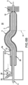
- Figure 7A shows a cross-sectional view of the catheter system 20 of the present invention, wherein the retractable sleeve structure 2 further comprises a curved inner tube portion 30 that is connected to the proximal end of inner tube 5 and extends in a curved direction within the housing structure 8.
- the curved inner tube portion 30 is manufactured from a metal or a biocompatible polymer and may coil up to and beyond 360 degrees within the housing structure 8.
- the middle tube 4, handle 6 and proximal ring 7 follow the curved inner tube portion 30.
- Handle 6 further comprises a sealable port 11 for controlling the contents and pressure of fluids in the sealed chamber 15. In another embodiment, the sealable port 11 may be positioned on the middle tube 4 separate from the handle 6.
- the housing structure has a first end 33 that is affixed to outer tube 3 and a second end 34 that is affixed to the curved inner tube portion 30.
- a force in the proximal direction is applied to the handle 6, thereby retracting the handle 6 and the retractable sleeve structure 2 over the curved inner tube portion 30 as shown in Figure 7B .
- the sleeve tip 16 therefore withdraws.
- the sleeve tip 16 may have a micro-orifice 18 to permit air to evacuate the sealed chamber 15 prior to or while the sealed chamber 15 is filled with a pressurized fluid 10 through the sealable port 11.
- this embodiment has the advantage of not requiring housing structures equal to or longer than twice the length of the stent (i.e. the length of the housing can be shorter than 2L ), thereby making the catheter system more compact and easier to use.
- FIGS 8A - 8D One method is illustrated by Figures 8A - 8D .
- the first step of one example is shown in Figure 8A and comprises compressing at least a portion of intravascular device 1, for example a fully crimped stent, around an inner tube 5 using a holding device 19.
- the next step, shown in Figure 8B comprises applying a force in the distal direction, for example to the handle of the sleeve tip (not shown), such that the retractable sleeve structure moves in the distal direction to incrementally extend longitudinally over an exposed residual portion of the intravascular device.
- the axial rigidity of the sleeve tip 16 is accomplished by fluid pressurization through means discussed above.
- the method further comprises releasing the holding device 19 and pulling the catheter system proximally, as shown in Figure 8C .
- the process repeats, as shown in Figure 8D .
- the holding device 19 is compressed against a more distal location on the device 1 than in the previous step and at each cycle the fold of the sleeve tip is extended incrementally in the distal direction to eventually cover or sheath the entire device.
- the retractable sleeve structure 2 may be assembled with pressurized fluid in the sealed chamber 15.
- the sealed chamber may be deflated once the device is mounted and prior to use.
- the method comprises placing a intravascular device in a crimped state on the inner tube while the handle of the retractable sleeve structure is positioned near the proximal end of the housing structure, such that the sleeve tip is fully withdrawn.
- a force in the distal direction is applied to the handle, such that the retractable sleeve structure moves distally against the mounted intravascular device.
- the sleeve tip Upon contact with the mounted intravascular device, the sleeve tip naturally folds around the intravascular device.
- a holding device is positioned at the distal end of the intravascular device holding it in place as the sleeve tip folds over the device. The fold of the sleeve tip is extended to cover or sheath the entire intravascular device.
- the device may be any stent or graft device, which are well known in the art. Any stent design may be utilized in connection with the present invention.
- the stent consists of separate segments designed to expand independently from each other as the sleeve tip is withdrawn; however, it should be understood that the invention is not limited to any particular stent design or structure.
- a stent or graft having either separate segments or a unitary design i.e., without separate stent segments designed to expand independently from each other
- the invention further contemplates stents or grafts having diameters of variable sizes and different lengths.
- NIRflex stent which is manufactured by Medinol, Ltd., as described in U.S. Patent No. 6,723,119 .
- Another example of a suitable self-expanding stent is described in US Patent Nos. 6,503,270 and 6,355,059 .
Landscapes
- Health & Medical Sciences (AREA)
- Engineering & Computer Science (AREA)
- Biomedical Technology (AREA)
- Cardiology (AREA)
- Oral & Maxillofacial Surgery (AREA)
- Transplantation (AREA)
- Heart & Thoracic Surgery (AREA)
- Vascular Medicine (AREA)
- Life Sciences & Earth Sciences (AREA)
- Animal Behavior & Ethology (AREA)
- General Health & Medical Sciences (AREA)
- Public Health (AREA)
- Veterinary Medicine (AREA)
- Media Introduction/Drainage Providing Device (AREA)
- Surgical Instruments (AREA)
- Measuring Pulse, Heart Rate, Blood Pressure Or Blood Flow (AREA)
Claims (14)
- Kathetersystem (20) mit einem distalen Ende (13) und einem proximalen Ende (14), wobei das Kathetersystem aufweist:eine Innenröhre (5) mit einem ersten Lumen;eine Außenröhre (3) mit einem zweiten Lumen, wobei die Innenröhre (5) durch das zweite Lumen verläuft;eine einziehbare Hülsenstruktur (2), die zwischen der Innenröhre (5) und der Außenröhre (3) positioniert ist, wobei die einziehbare Hülsenstruktur eine Mittelröhre (4) und eine Hülsenspitze (16) aufweist; undeine Gehäusestruktur (8) an dem proximalen Ende des Kathetersystems (20), wobei die Gehäusestruktur ein distales Ende (8a) und ein proximales Ende (8b) aufweist,dadurch gekennzeichnet, dass die Innenröhre (5) einen gekrümmten Innenröhrenabschnitt (30) aufweist, der innerhalb der Gehäusestruktur verläuft und an der Gehäusestruktur (8) befestigt ist;wobei die einziehbare Hülse (2) und die Innenröhre (5) eine abgedichtete Kammer (15) bilden.
- Kathetersystem (20) nach Anspruch 1, wobei sich der gekrümmte Innenröhrenabschnitt (30) innerhalb der Gehäusestruktur (8) befindet und/oder ein Metall oder ein biokompatibles Polymer aufweist, im Besonderen Polyetheretherketon (PEEK), Polyethylenterephthalat (PET), Polyimid (PI) oder Nylon.
- Kathetersystem (20) nach einem der Ansprüche 1 bis 2, wobei der gekrümmte Innenröhrenabschnitt (30) innerhalb der Gehäusestruktur (8) bis 360 Grad oder darüber hinaus aufgerollt ist.
- Kathetersystem (20) nach einem der Ansprüche 1 bis 3, wobei die Mittelröhre (4) mit dem gekrümmten Innenröhrenabschnitt (30) flächengleich ist.
- Kathetersystem (20) nach einem der Ansprüche 1 bis 4, wobei die Außenröhre (3) und die Innenröhre (5) relativ zueinander befestigt sind.
- Kathetersystem (20) nach einem der Ansprüche 1 bis 5, wobei das Kathetersystem (20) ferner eine intravaskuläre Vorrichtung (1) aufweist.
- Kathetersystem (20) nach einem der Ansprüche 1 bis 6, wobei die einziehbare Hülsenstruktur (2) einen abdichtbaren Anschluss (11) aufweist, der sich im Besonderen in einem Griff (6) befindet.
- Kathetersystem (20) nach einem der Ansprüche 1 bis 7, wobei die Hülsenspitze (16) eine Mikroöffnung (18) beinhaltet, die einen Durchmesser von 30-40 Mikrometern aufweist und/oder einen Falz (17) bildet.
- Kathetersystem (20) nach einem der Ansprüche 1 bis 8, wobei die einziehbare Hülsenstruktur (2) ultradünnes Polyethylenterephthalat oder Polyimid aufweist.
- Kathetersystem (20) nach einem der Ansprüche 1 bis 9, ferner aufweisend einen distalen Ring (12), der die Hülsenspitze (16) mit der Innenröhre (5) und/oder einem Führungsdraht (9) verbindet.
- Kathetersystem (20) nach einem der Ansprüche 1 bis 10, wobei die abgedichtete Kammer (15) ein Fluid oder ein Hydrogel enthält.
- Kathetersystem (20) nach einem der Ansprüche 1 bis 11, aufweisend einen radialen Raum (W) zwischen der Hülsenspitze (16) und der Innenröhre (5).
- Kathetersystem (20) nach einem der Ansprüche 1 bis 12, wobei die einziehbare Hülse (2) relativ zu der Innenröhre (5) und der Außenröhre (3) beweglich ist und/oder der gekrümmte Innenröhrenabschnitt (30) unbeweglich an dem Gehäuse (8) befestigt ist.
- Kathetersystem (20) nach einem der Ansprüche 1 bis 13, ferner aufweisend einen Griff (6), der mit der einziehbaren Hülse (2) an dem proximalen Ende der Mittelröhre (4) verbunden ist, wobei der Griff (6) im Besonderen einen proximalen Ring (7) aufweist, der die Mittelröhre (4) mit der Innenröhre (5) verbindet.
Applications Claiming Priority (3)
| Application Number | Priority Date | Filing Date | Title |
|---|---|---|---|
| US13/560,132 US9364358B2 (en) | 2012-07-27 | 2012-07-27 | Catheter with retractable cover and pressurized fluid |
| EP13824514.7A EP2877124B1 (de) | 2012-07-27 | 2013-07-23 | Katheter mit einziehbarer hülse und verfahren zur verwendung des kathetersystems |
| PCT/IB2013/002770 WO2014033553A2 (en) | 2012-07-27 | 2013-07-23 | Catheter with retractable sleeve and method of using catheter system |
Related Parent Applications (2)
| Application Number | Title | Priority Date | Filing Date |
|---|---|---|---|
| EP13824514.7A Division-Into EP2877124B1 (de) | 2012-07-27 | 2013-07-23 | Katheter mit einziehbarer hülse und verfahren zur verwendung des kathetersystems |
| EP13824514.7A Division EP2877124B1 (de) | 2012-07-27 | 2013-07-23 | Katheter mit einziehbarer hülse und verfahren zur verwendung des kathetersystems |
Publications (2)
| Publication Number | Publication Date |
|---|---|
| EP3563806A1 EP3563806A1 (de) | 2019-11-06 |
| EP3563806B1 true EP3563806B1 (de) | 2023-06-28 |
Family
ID=49995554
Family Applications (3)
| Application Number | Title | Priority Date | Filing Date |
|---|---|---|---|
| EP13824514.7A Active EP2877124B1 (de) | 2012-07-27 | 2013-07-23 | Katheter mit einziehbarer hülse und verfahren zur verwendung des kathetersystems |
| EP17167574.7A Pending EP3213719A1 (de) | 2012-07-27 | 2013-07-23 | Katheter mit einziehbarer hülse |
| EP19178195.4A Active EP3563806B1 (de) | 2012-07-27 | 2013-07-23 | Katheter mit einziehbarer hülse |
Family Applications Before (2)
| Application Number | Title | Priority Date | Filing Date |
|---|---|---|---|
| EP13824514.7A Active EP2877124B1 (de) | 2012-07-27 | 2013-07-23 | Katheter mit einziehbarer hülse und verfahren zur verwendung des kathetersystems |
| EP17167574.7A Pending EP3213719A1 (de) | 2012-07-27 | 2013-07-23 | Katheter mit einziehbarer hülse |
Country Status (13)
| Country | Link |
|---|---|
| US (4) | US9364358B2 (de) |
| EP (3) | EP2877124B1 (de) |
| JP (1) | JP6332269B2 (de) |
| CN (2) | CN104582636B (de) |
| AU (2) | AU2013308120C1 (de) |
| BR (1) | BR112015001813B1 (de) |
| CA (2) | CA2878799C (de) |
| ES (2) | ES2952189T3 (de) |
| HK (1) | HK1205671A1 (de) |
| IL (3) | IL236918B (de) |
| IN (1) | IN2014DN11224A (de) |
| RU (2) | RU2737289C2 (de) |
| WO (1) | WO2014033553A2 (de) |
Families Citing this family (31)
| Publication number | Priority date | Publication date | Assignee | Title |
|---|---|---|---|---|
| US9539081B2 (en) | 2009-12-02 | 2017-01-10 | Surefire Medical, Inc. | Method of operating a microvalve protection device |
| US8579964B2 (en) | 2010-05-05 | 2013-11-12 | Neovasc Inc. | Transcatheter mitral valve prosthesis |
| US9554897B2 (en) | 2011-04-28 | 2017-01-31 | Neovasc Tiara Inc. | Methods and apparatus for engaging a valve prosthesis with tissue |
| US9308087B2 (en) | 2011-04-28 | 2016-04-12 | Neovasc Tiara Inc. | Sequentially deployed transcatheter mitral valve prosthesis |
| US9345573B2 (en) | 2012-05-30 | 2016-05-24 | Neovasc Tiara Inc. | Methods and apparatus for loading a prosthesis onto a delivery system |
| US9364358B2 (en) | 2012-07-27 | 2016-06-14 | Medinol Ltd. | Catheter with retractable cover and pressurized fluid |
| US9572665B2 (en) | 2013-04-04 | 2017-02-21 | Neovasc Tiara Inc. | Methods and apparatus for delivering a prosthetic valve to a beating heart |
| US9968740B2 (en) | 2014-03-25 | 2018-05-15 | Surefire Medical, Inc. | Closed tip dynamic microvalve protection device |
| US20160287839A1 (en) | 2015-03-31 | 2016-10-06 | Surefire Medical, Inc. | Apparatus and Method for Infusing an Immunotherapy Agent to a Solid Tumor for Treatment |
| US10433952B2 (en) | 2016-01-29 | 2019-10-08 | Neovasc Tiara Inc. | Prosthetic valve for avoiding obstruction of outflow |
| US10780250B1 (en) | 2016-09-19 | 2020-09-22 | Surefire Medical, Inc. | System and method for selective pressure-controlled therapeutic delivery |
| US11400263B1 (en) | 2016-09-19 | 2022-08-02 | Trisalus Life Sciences, Inc. | System and method for selective pressure-controlled therapeutic delivery |
| CN109996581B (zh) | 2016-11-21 | 2021-10-15 | 内奥瓦斯克迪亚拉公司 | 用于快速收回经导管心脏瓣膜递送系统的方法和系统 |
| WO2018164907A1 (en) * | 2017-03-10 | 2018-09-13 | Promedica Health System, Inc. | Aortic valve no exchange catheter |
| US10588636B2 (en) | 2017-03-20 | 2020-03-17 | Surefire Medical, Inc. | Dynamic reconfigurable microvalve protection device |
| EP3388033A1 (de) * | 2017-04-11 | 2018-10-17 | Koninklijke Philips N.V. | Intravaskuläre vorrichtung mit von intravaskulärem flüssigkeitsdruckausgleich unterstützter expandierbarer radialer erweiterung |
| CA3069991C (en) | 2017-06-29 | 2022-05-31 | Open Stent Solution | Intraluminal support structure and prosthetic valve from the same |
| WO2019036810A1 (en) | 2017-08-25 | 2019-02-28 | Neovasc Tiara Inc. | TRANSCATHETER MITRAL VALVULE PROSTHESIS WITH SEQUENTIAL DEPLOYMENT |
| CN110575285A (zh) | 2018-06-08 | 2019-12-17 | 上海微创心通医疗科技有限公司 | 植入物输送管件和植入物输送系统 |
| US11850398B2 (en) | 2018-08-01 | 2023-12-26 | Trisalus Life Sciences, Inc. | Systems and methods for pressure-facilitated therapeutic agent delivery |
| US11338117B2 (en) | 2018-10-08 | 2022-05-24 | Trisalus Life Sciences, Inc. | Implantable dual pathway therapeutic agent delivery port |
| CN113271890A (zh) | 2018-11-08 | 2021-08-17 | 内奥瓦斯克迪亚拉公司 | 经导管二尖瓣假体的心室展开 |
| CA3132873A1 (en) | 2019-03-08 | 2020-09-17 | Neovasc Tiara Inc. | Retrievable prosthesis delivery system |
| JP7438236B2 (ja) | 2019-04-01 | 2024-02-26 | ニオバスク ティアラ インコーポレイテッド | 制御可能に展開可能な補綴弁 |
| CN113924065A (zh) | 2019-04-10 | 2022-01-11 | 内奥瓦斯克迪亚拉公司 | 具有自然血流的假体瓣膜 |
| EP3972673A4 (de) | 2019-05-20 | 2023-06-07 | Neovasc Tiara Inc. | Einführungsvorrichtung mit hämostasemechanismus |
| CA3143344A1 (en) | 2019-06-20 | 2020-12-24 | Neovasc Tiara Inc. | Low profile prosthetic mitral valve |
| CN113116412B (zh) * | 2019-12-30 | 2024-03-29 | 北京术锐机器人股份有限公司 | 一种微型手术工具头 |
| CN112494786B (zh) * | 2021-02-05 | 2021-05-07 | 北京泰杰伟业科技有限公司 | 球囊导管装置 |
| US20230309962A1 (en) * | 2022-03-29 | 2023-10-05 | Boston Scientific Scimed, Inc. | Telescoping catheter |
| WO2023215558A1 (en) * | 2022-05-06 | 2023-11-09 | Boston Scientific Scimed, Inc. | Intravascular imaging devices |
Citations (2)
| Publication number | Priority date | Publication date | Assignee | Title |
|---|---|---|---|---|
| US20040143315A1 (en) * | 2003-01-17 | 2004-07-22 | Bruun Steven R. | Deployment system for an endoluminal device |
| US20110118817A1 (en) * | 2009-11-17 | 2011-05-19 | Boston Scientific Scimed, Inc. | Stent delivery system |
Family Cites Families (30)
| Publication number | Priority date | Publication date | Assignee | Title |
|---|---|---|---|---|
| ES8705239A1 (es) | 1984-12-05 | 1987-05-01 | Medinvent Sa | Un dispositivo para implantar,mediante insercion en un lugarde dificil acceso, una protesis sustancialmente tubular y radialmente expandible |
| US5707376A (en) * | 1992-08-06 | 1998-01-13 | William Cook Europe A/S | Stent introducer and method of use |
| US5571135A (en) | 1993-10-22 | 1996-11-05 | Scimed Life Systems Inc. | Stent delivery apparatus and method |
| US5569221A (en) | 1994-07-07 | 1996-10-29 | Ep Technologies, Inc. | Catheter component bond and method |
| US5571168A (en) * | 1995-04-05 | 1996-11-05 | Scimed Lifesystems Inc | Pull back stent delivery system |
| US5534007A (en) | 1995-05-18 | 1996-07-09 | Scimed Life Systems, Inc. | Stent deployment catheter with collapsible sheath |
| BE1011180A6 (fr) * | 1997-05-27 | 1999-06-01 | Medicorp R & D Benelux Sa | Endoprothese luminale auto expansible. |
| US6059813A (en) | 1998-11-06 | 2000-05-09 | Scimed Life Systems, Inc. | Rolling membrane stent delivery system |
| US6544278B1 (en) | 1998-11-06 | 2003-04-08 | Scimed Life Systems, Inc. | Rolling membrane stent delivery system |
| US6503270B1 (en) | 1998-12-03 | 2003-01-07 | Medinol Ltd. | Serpentine coiled ladder stent |
| US6355059B1 (en) | 1998-12-03 | 2002-03-12 | Medinol, Ltd. | Serpentine coiled ladder stent |
| US6723119B2 (en) | 2000-03-01 | 2004-04-20 | Medinol Ltd. | Longitudinally flexible stent |
| US7323006B2 (en) * | 2004-03-30 | 2008-01-29 | Xtent, Inc. | Rapid exchange interventional devices and methods |
| WO2005115254A2 (en) * | 2004-05-17 | 2005-12-08 | Datascope Investment Corp. | Surgical stapling system |
| EP1621160B1 (de) | 2004-07-28 | 2008-03-26 | Cordis Corporation | Einführvorrichtung mit einer niedrigen Entfaltungskraft |
| US7955370B2 (en) * | 2004-08-06 | 2011-06-07 | Boston Scientific Scimed, Inc. | Stent delivery system |
| US7632296B2 (en) | 2005-03-03 | 2009-12-15 | Boston Scientific Scimed, Inc. | Rolling membrane with hydraulic recapture means for self expanding stent |
| US20070208350A1 (en) * | 2006-03-06 | 2007-09-06 | Gunderson Richard C | Implantable medical endoprosthesis delivery systems |
| US20070219617A1 (en) * | 2006-03-17 | 2007-09-20 | Sean Saint | Handle for Long Self Expanding Stent |
| US8118853B2 (en) | 2006-06-19 | 2012-02-21 | Cook Medical Technologies Llc | Prosthesis delivery and deployment device |
| US8845712B2 (en) | 2008-01-15 | 2014-09-30 | W. L. Gore & Associates, Inc. | Pleated deployment sheath |
| DE102008015781B4 (de) * | 2008-03-26 | 2011-09-29 | Malte Neuss | Vorrichtung zum Verschluss von Defekten im Gefäßsystem |
| BRPI0913877A2 (pt) * | 2008-06-30 | 2015-10-27 | Bolton Medical Inc | aneurismas da aorta abdominal: sistemas e métodos de uso |
| US20100262157A1 (en) | 2009-04-14 | 2010-10-14 | Medtronic Vascular, Inc. | Methods and Systems for Loading a Stent |
| US8016872B2 (en) | 2009-12-22 | 2011-09-13 | Cook Medical Technologies Llc | Deployment and dilation with an expandable roll sock delivery system |
| US9132064B2 (en) * | 2009-12-23 | 2015-09-15 | Avent, Inc. | Enteral feeding catheter assembly incorporating an indicator |
| US20120259355A1 (en) * | 2011-04-08 | 2012-10-11 | Kyphon Sarl | Retractable inflatable bone tamp |
| US10213329B2 (en) | 2011-08-12 | 2019-02-26 | W. L. Gore & Associates, Inc. | Evertable sheath devices, systems, and methods |
| US9364358B2 (en) * | 2012-07-27 | 2016-06-14 | Medinol Ltd. | Catheter with retractable cover and pressurized fluid |
| US9445928B2 (en) * | 2013-05-30 | 2016-09-20 | Medtronic Vascular, Inc. | Delivery system having a single handed deployment handle for a retractable outer sheath |
-
2012
- 2012-07-27 US US13/560,132 patent/US9364358B2/en active Active
-
2013
- 2013-07-23 JP JP2015523627A patent/JP6332269B2/ja active Active
- 2013-07-23 US US14/775,569 patent/US10226369B2/en active Active
- 2013-07-23 CA CA2878799A patent/CA2878799C/en not_active Expired - Fee Related
- 2013-07-23 RU RU2017103684A patent/RU2737289C2/ru active
- 2013-07-23 CA CA3013622A patent/CA3013622A1/en not_active Abandoned
- 2013-07-23 RU RU2014152907A patent/RU2610213C2/ru active
- 2013-07-23 ES ES19178195T patent/ES2952189T3/es active Active
- 2013-07-23 ES ES13824514T patent/ES2739837T3/es active Active
- 2013-07-23 AU AU2013308120A patent/AU2013308120C1/en not_active Ceased
- 2013-07-23 EP EP13824514.7A patent/EP2877124B1/de active Active
- 2013-07-23 IN IN11224DEN2014 patent/IN2014DN11224A/en unknown
- 2013-07-23 EP EP17167574.7A patent/EP3213719A1/de active Pending
- 2013-07-23 BR BR112015001813-0A patent/BR112015001813B1/pt active IP Right Grant
- 2013-07-23 CN CN201380038985.0A patent/CN104582636B/zh active Active
- 2013-07-23 WO PCT/IB2013/002770 patent/WO2014033553A2/en active Application Filing
- 2013-07-23 EP EP19178195.4A patent/EP3563806B1/de active Active
- 2013-07-23 CN CN201711154634.2A patent/CN107874880B/zh active Active
-
2015
- 2015-01-25 IL IL236918A patent/IL236918B/en active IP Right Grant
- 2015-06-30 HK HK15106195.3A patent/HK1205671A1/xx unknown
-
2016
- 2016-09-29 AU AU2016234958A patent/AU2016234958C1/en not_active Ceased
-
2018
- 2018-06-25 IL IL260252A patent/IL260252B/en active IP Right Grant
-
2019
- 2019-01-18 US US16/251,591 patent/US10973667B2/en active Active
-
2020
- 2020-06-18 IL IL275491A patent/IL275491B/en unknown
-
2021
- 2021-03-12 US US17/199,970 patent/US11872148B2/en active Active
Patent Citations (2)
| Publication number | Priority date | Publication date | Assignee | Title |
|---|---|---|---|---|
| US20040143315A1 (en) * | 2003-01-17 | 2004-07-22 | Bruun Steven R. | Deployment system for an endoluminal device |
| US20110118817A1 (en) * | 2009-11-17 | 2011-05-19 | Boston Scientific Scimed, Inc. | Stent delivery system |
Also Published As
Similar Documents
| Publication | Publication Date | Title |
|---|---|---|
| US10973667B2 (en) | Catheter with retractable cover and pressurized fluid | |
| EP0236333B1 (de) | Implantierungsanordnung und verfahren zur implantierung in ein gefäss | |
| US8435279B2 (en) | Delivery system for a device such as a stent | |
| US20030125764A1 (en) | Catheter | |
| EP1333778B1 (de) | Stentzuführsystem mit rollmembran | |
| JP2004531289A6 (ja) | 改良された折り返しを有する薄膜ステントデリバリーシステム | |
| JPH10277159A (ja) | ステント供給カテーテルシステム | |
| JP2003530200A (ja) | 引き戻し可能なバルーンを備えたステント搬送カテーテル | |
| WO2015141399A1 (ja) | 生体留置物デリバリーシステム | |
| JP2012205838A (ja) | ステントグラフトデリバリー装置 | |
| EP1399090A1 (de) | Katheter zur implantation eines filters in ein blutgefäss | |
| IE20020531A1 (en) | A Catheter |
Legal Events
| Date | Code | Title | Description |
|---|---|---|---|
| PUAI | Public reference made under article 153(3) epc to a published international application that has entered the european phase |
Free format text: ORIGINAL CODE: 0009012 |
|
| STAA | Information on the status of an ep patent application or granted ep patent |
Free format text: STATUS: THE APPLICATION HAS BEEN PUBLISHED |
|
| AC | Divisional application: reference to earlier application |
Ref document number: 2877124 Country of ref document: EP Kind code of ref document: P |
|
| AK | Designated contracting states |
Kind code of ref document: A1 Designated state(s): AL AT BE BG CH CY CZ DE DK EE ES FI FR GB GR HR HU IE IS IT LI LT LU LV MC MK MT NL NO PL PT RO RS SE SI SK SM TR |
|
| STAA | Information on the status of an ep patent application or granted ep patent |
Free format text: STATUS: REQUEST FOR EXAMINATION WAS MADE |
|
| 17P | Request for examination filed |
Effective date: 20200417 |
|
| RBV | Designated contracting states (corrected) |
Designated state(s): AL AT BE BG CH CY CZ DE DK EE ES FI FR GB GR HR HU IE IS IT LI LT LU LV MC MK MT NL NO PL PT RO RS SE SI SK SM TR |
|
| REG | Reference to a national code |
Ref country code: HK Ref legal event code: DE Ref document number: 40008800 Country of ref document: HK |
|
| STAA | Information on the status of an ep patent application or granted ep patent |
Free format text: STATUS: EXAMINATION IS IN PROGRESS |
|
| 17Q | First examination report despatched |
Effective date: 20210127 |
|
| RIC1 | Information provided on ipc code assigned before grant |
Ipc: A61F 2/966 20130101ALI20220622BHEP Ipc: A61F 2/95 20130101ALI20220622BHEP Ipc: A61F 2/24 20060101AFI20220622BHEP |
|
| GRAP | Despatch of communication of intention to grant a patent |
Free format text: ORIGINAL CODE: EPIDOSNIGR1 |
|
| STAA | Information on the status of an ep patent application or granted ep patent |
Free format text: STATUS: GRANT OF PATENT IS INTENDED |
|
| INTG | Intention to grant announced |
Effective date: 20220826 |
|
| GRAJ | Information related to disapproval of communication of intention to grant by the applicant or resumption of examination proceedings by the epo deleted |
Free format text: ORIGINAL CODE: EPIDOSDIGR1 |
|
| STAA | Information on the status of an ep patent application or granted ep patent |
Free format text: STATUS: EXAMINATION IS IN PROGRESS |
|
| INTC | Intention to grant announced (deleted) | ||
| GRAJ | Information related to disapproval of communication of intention to grant by the applicant or resumption of examination proceedings by the epo deleted |
Free format text: ORIGINAL CODE: EPIDOSDIGR1 |
|
| STAA | Information on the status of an ep patent application or granted ep patent |
Free format text: STATUS: GRANT OF PATENT IS INTENDED |
|
| GRAP | Despatch of communication of intention to grant a patent |
Free format text: ORIGINAL CODE: EPIDOSNIGR1 |
|
| INTG | Intention to grant announced |
Effective date: 20230404 |
|
| GRAS | Grant fee paid |
Free format text: ORIGINAL CODE: EPIDOSNIGR3 |
|
| GRAA | (expected) grant |
Free format text: ORIGINAL CODE: 0009210 |
|
| STAA | Information on the status of an ep patent application or granted ep patent |
Free format text: STATUS: THE PATENT HAS BEEN GRANTED |
|
| P01 | Opt-out of the competence of the unified patent court (upc) registered |
Effective date: 20230510 |
|
| AC | Divisional application: reference to earlier application |
Ref document number: 2877124 Country of ref document: EP Kind code of ref document: P |
|
| AK | Designated contracting states |
Kind code of ref document: B1 Designated state(s): AL AT BE BG CH CY CZ DE DK EE ES FI FR GB GR HR HU IE IS IT LI LT LU LV MC MK MT NL NO PL PT RO RS SE SI SK SM TR |
|
| REG | Reference to a national code |
Ref country code: CH Ref legal event code: EP |
|
| REG | Reference to a national code |
Ref country code: AT Ref legal event code: REF Ref document number: 1582057 Country of ref document: AT Kind code of ref document: T Effective date: 20230715 |
|
| REG | Reference to a national code |
Ref country code: IE Ref legal event code: FG4D |
|
| REG | Reference to a national code |
Ref country code: DE Ref legal event code: R096 Ref document number: 602013084146 Country of ref document: DE |
|
| PGFP | Annual fee paid to national office [announced via postgrant information from national office to epo] |
Ref country code: NL Payment date: 20230726 Year of fee payment: 11 |
|
| REG | Reference to a national code |
Ref country code: NL Ref legal event code: FP |
|
| REG | Reference to a national code |
Ref country code: LT Ref legal event code: MG9D |
|
| REG | Reference to a national code |
Ref country code: ES Ref legal event code: FG2A Ref document number: 2952189 Country of ref document: ES Kind code of ref document: T3 Effective date: 20231030 |
|
| PG25 | Lapsed in a contracting state [announced via postgrant information from national office to epo] |
Ref country code: SE Free format text: LAPSE BECAUSE OF FAILURE TO SUBMIT A TRANSLATION OF THE DESCRIPTION OR TO PAY THE FEE WITHIN THE PRESCRIBED TIME-LIMIT Effective date: 20230628 Ref country code: NO Free format text: LAPSE BECAUSE OF FAILURE TO SUBMIT A TRANSLATION OF THE DESCRIPTION OR TO PAY THE FEE WITHIN THE PRESCRIBED TIME-LIMIT Effective date: 20230928 |
|
| PGFP | Annual fee paid to national office [announced via postgrant information from national office to epo] |
Ref country code: IE Payment date: 20230727 Year of fee payment: 11 Ref country code: GB Payment date: 20230727 Year of fee payment: 11 Ref country code: ES Payment date: 20230804 Year of fee payment: 11 |
|
| REG | Reference to a national code |
Ref country code: AT Ref legal event code: MK05 Ref document number: 1582057 Country of ref document: AT Kind code of ref document: T Effective date: 20230628 |
|
| PG25 | Lapsed in a contracting state [announced via postgrant information from national office to epo] |
Ref country code: RS Free format text: LAPSE BECAUSE OF FAILURE TO SUBMIT A TRANSLATION OF THE DESCRIPTION OR TO PAY THE FEE WITHIN THE PRESCRIBED TIME-LIMIT Effective date: 20230628 Ref country code: LV Free format text: LAPSE BECAUSE OF FAILURE TO SUBMIT A TRANSLATION OF THE DESCRIPTION OR TO PAY THE FEE WITHIN THE PRESCRIBED TIME-LIMIT Effective date: 20230628 Ref country code: LT Free format text: LAPSE BECAUSE OF FAILURE TO SUBMIT A TRANSLATION OF THE DESCRIPTION OR TO PAY THE FEE WITHIN THE PRESCRIBED TIME-LIMIT Effective date: 20230628 Ref country code: HR Free format text: LAPSE BECAUSE OF FAILURE TO SUBMIT A TRANSLATION OF THE DESCRIPTION OR TO PAY THE FEE WITHIN THE PRESCRIBED TIME-LIMIT Effective date: 20230628 Ref country code: GR Free format text: LAPSE BECAUSE OF FAILURE TO SUBMIT A TRANSLATION OF THE DESCRIPTION OR TO PAY THE FEE WITHIN THE PRESCRIBED TIME-LIMIT Effective date: 20230929 |
|
| PGFP | Annual fee paid to national office [announced via postgrant information from national office to epo] |
Ref country code: FR Payment date: 20230725 Year of fee payment: 11 |
|
| PG25 | Lapsed in a contracting state [announced via postgrant information from national office to epo] |
Ref country code: FI Free format text: LAPSE BECAUSE OF FAILURE TO SUBMIT A TRANSLATION OF THE DESCRIPTION OR TO PAY THE FEE WITHIN THE PRESCRIBED TIME-LIMIT Effective date: 20230628 |
|
| PG25 | Lapsed in a contracting state [announced via postgrant information from national office to epo] |
Ref country code: SK Free format text: LAPSE BECAUSE OF FAILURE TO SUBMIT A TRANSLATION OF THE DESCRIPTION OR TO PAY THE FEE WITHIN THE PRESCRIBED TIME-LIMIT Effective date: 20230628 |
|
| PG25 | Lapsed in a contracting state [announced via postgrant information from national office to epo] |
Ref country code: IS Free format text: LAPSE BECAUSE OF FAILURE TO SUBMIT A TRANSLATION OF THE DESCRIPTION OR TO PAY THE FEE WITHIN THE PRESCRIBED TIME-LIMIT Effective date: 20231028 |
|
| PG25 | Lapsed in a contracting state [announced via postgrant information from national office to epo] |
Ref country code: SM Free format text: LAPSE BECAUSE OF FAILURE TO SUBMIT A TRANSLATION OF THE DESCRIPTION OR TO PAY THE FEE WITHIN THE PRESCRIBED TIME-LIMIT Effective date: 20230628 Ref country code: SK Free format text: LAPSE BECAUSE OF FAILURE TO SUBMIT A TRANSLATION OF THE DESCRIPTION OR TO PAY THE FEE WITHIN THE PRESCRIBED TIME-LIMIT Effective date: 20230628 Ref country code: RO Free format text: LAPSE BECAUSE OF FAILURE TO SUBMIT A TRANSLATION OF THE DESCRIPTION OR TO PAY THE FEE WITHIN THE PRESCRIBED TIME-LIMIT Effective date: 20230628 Ref country code: PT Free format text: LAPSE BECAUSE OF FAILURE TO SUBMIT A TRANSLATION OF THE DESCRIPTION OR TO PAY THE FEE WITHIN THE PRESCRIBED TIME-LIMIT Effective date: 20231030 Ref country code: IS Free format text: LAPSE BECAUSE OF FAILURE TO SUBMIT A TRANSLATION OF THE DESCRIPTION OR TO PAY THE FEE WITHIN THE PRESCRIBED TIME-LIMIT Effective date: 20231028 Ref country code: EE Free format text: LAPSE BECAUSE OF FAILURE TO SUBMIT A TRANSLATION OF THE DESCRIPTION OR TO PAY THE FEE WITHIN THE PRESCRIBED TIME-LIMIT Effective date: 20230628 Ref country code: CZ Free format text: LAPSE BECAUSE OF FAILURE TO SUBMIT A TRANSLATION OF THE DESCRIPTION OR TO PAY THE FEE WITHIN THE PRESCRIBED TIME-LIMIT Effective date: 20230628 Ref country code: AT Free format text: LAPSE BECAUSE OF FAILURE TO SUBMIT A TRANSLATION OF THE DESCRIPTION OR TO PAY THE FEE WITHIN THE PRESCRIBED TIME-LIMIT Effective date: 20230628 |
|
| PGFP | Annual fee paid to national office [announced via postgrant information from national office to epo] |
Ref country code: IT Payment date: 20230926 Year of fee payment: 11 |
|
| REG | Reference to a national code |
Ref country code: DE Ref legal event code: R119 Ref document number: 602013084146 Country of ref document: DE |
|
| PG25 | Lapsed in a contracting state [announced via postgrant information from national office to epo] |
Ref country code: PL Free format text: LAPSE BECAUSE OF FAILURE TO SUBMIT A TRANSLATION OF THE DESCRIPTION OR TO PAY THE FEE WITHIN THE PRESCRIBED TIME-LIMIT Effective date: 20230628 |
|
| REG | Reference to a national code |
Ref country code: CH Ref legal event code: PL |
|
| PG25 | Lapsed in a contracting state [announced via postgrant information from national office to epo] |
Ref country code: MC Free format text: LAPSE BECAUSE OF FAILURE TO SUBMIT A TRANSLATION OF THE DESCRIPTION OR TO PAY THE FEE WITHIN THE PRESCRIBED TIME-LIMIT Effective date: 20230628 |
|
| REG | Reference to a national code |
Ref country code: BE Ref legal event code: MM Effective date: 20230731 |
|
| PG25 | Lapsed in a contracting state [announced via postgrant information from national office to epo] |
Ref country code: LU Free format text: LAPSE BECAUSE OF NON-PAYMENT OF DUE FEES Effective date: 20230723 |
|
| PG25 | Lapsed in a contracting state [announced via postgrant information from national office to epo] |
Ref country code: MC Free format text: LAPSE BECAUSE OF FAILURE TO SUBMIT A TRANSLATION OF THE DESCRIPTION OR TO PAY THE FEE WITHIN THE PRESCRIBED TIME-LIMIT Effective date: 20230628 Ref country code: LU Free format text: LAPSE BECAUSE OF NON-PAYMENT OF DUE FEES Effective date: 20230723 |
|
| PG25 | Lapsed in a contracting state [announced via postgrant information from national office to epo] |
Ref country code: DK Free format text: LAPSE BECAUSE OF FAILURE TO SUBMIT A TRANSLATION OF THE DESCRIPTION OR TO PAY THE FEE WITHIN THE PRESCRIBED TIME-LIMIT Effective date: 20230628 Ref country code: DE Free format text: LAPSE BECAUSE OF NON-PAYMENT OF DUE FEES Effective date: 20240201 Ref country code: CH Free format text: LAPSE BECAUSE OF NON-PAYMENT OF DUE FEES Effective date: 20230731 |
|
| PLBE | No opposition filed within time limit |
Free format text: ORIGINAL CODE: 0009261 |
|
| STAA | Information on the status of an ep patent application or granted ep patent |
Free format text: STATUS: NO OPPOSITION FILED WITHIN TIME LIMIT |
|
| PG25 | Lapsed in a contracting state [announced via postgrant information from national office to epo] |
Ref country code: BE Free format text: LAPSE BECAUSE OF NON-PAYMENT OF DUE FEES Effective date: 20230731 |
|
| 26N | No opposition filed |
Effective date: 20240402 |