EP3563798B1 - Procédé de production d'outil de nettoyage interdentaire - Google Patents
Procédé de production d'outil de nettoyage interdentaire Download PDFInfo
- Publication number
- EP3563798B1 EP3563798B1 EP17888780.8A EP17888780A EP3563798B1 EP 3563798 B1 EP3563798 B1 EP 3563798B1 EP 17888780 A EP17888780 A EP 17888780A EP 3563798 B1 EP3563798 B1 EP 3563798B1
- Authority
- EP
- European Patent Office
- Prior art keywords
- mold
- elastomer
- base
- portions
- recessed
- Prior art date
- Legal status (The legal status is an assumption and is not a legal conclusion. Google has not performed a legal analysis and makes no representation as to the accuracy of the status listed.)
- Active
Links
Images


Classifications
-
- B—PERFORMING OPERATIONS; TRANSPORTING
- B29—WORKING OF PLASTICS; WORKING OF SUBSTANCES IN A PLASTIC STATE IN GENERAL
- B29C—SHAPING OR JOINING OF PLASTICS; SHAPING OF MATERIAL IN A PLASTIC STATE, NOT OTHERWISE PROVIDED FOR; AFTER-TREATMENT OF THE SHAPED PRODUCTS, e.g. REPAIRING
- B29C45/00—Injection moulding, i.e. forcing the required volume of moulding material through a nozzle into a closed mould; Apparatus therefor
- B29C45/16—Making multilayered or multicoloured articles
-
- A—HUMAN NECESSITIES
- A46—BRUSHWARE
- A46B—BRUSHES
- A46B3/00—Brushes characterised by the way in which the bristles are fixed or joined in or on the brush body or carrier
- A46B3/04—Brushes characterised by the way in which the bristles are fixed or joined in or on the brush body or carrier by mouldable materials, e.g. metals, cellulose derivatives, plastics
-
- A—HUMAN NECESSITIES
- A46—BRUSHWARE
- A46B—BRUSHES
- A46B3/00—Brushes characterised by the way in which the bristles are fixed or joined in or on the brush body or carrier
- A46B3/22—Brushes characterised by the way in which the bristles are fixed or joined in or on the brush body or carrier rubber bristles being fixed in or on brush bodies
-
- A—HUMAN NECESSITIES
- A46—BRUSHWARE
- A46B—BRUSHES
- A46B5/00—Brush bodies; Handles integral with brushware
- A46B5/02—Brush bodies; Handles integral with brushware specially shaped for holding by the hand
-
- A—HUMAN NECESSITIES
- A46—BRUSHWARE
- A46D—MANUFACTURE OF BRUSHES
- A46D3/00—Preparing, i.e. Manufacturing brush bodies
-
- A—HUMAN NECESSITIES
- A46—BRUSHWARE
- A46D—MANUFACTURE OF BRUSHES
- A46D3/00—Preparing, i.e. Manufacturing brush bodies
- A46D3/005—Preparing, i.e. Manufacturing brush bodies by moulding or casting a body around bristles or tufts of bristles
-
- A—HUMAN NECESSITIES
- A61—MEDICAL OR VETERINARY SCIENCE; HYGIENE
- A61C—DENTISTRY; APPARATUS OR METHODS FOR ORAL OR DENTAL HYGIENE
- A61C15/00—Devices for cleaning between the teeth
- A61C15/02—Toothpicks
-
- B—PERFORMING OPERATIONS; TRANSPORTING
- B29—WORKING OF PLASTICS; WORKING OF SUBSTANCES IN A PLASTIC STATE IN GENERAL
- B29C—SHAPING OR JOINING OF PLASTICS; SHAPING OF MATERIAL IN A PLASTIC STATE, NOT OTHERWISE PROVIDED FOR; AFTER-TREATMENT OF THE SHAPED PRODUCTS, e.g. REPAIRING
- B29C45/00—Injection moulding, i.e. forcing the required volume of moulding material through a nozzle into a closed mould; Apparatus therefor
- B29C45/0005—Injection moulding, i.e. forcing the required volume of moulding material through a nozzle into a closed mould; Apparatus therefor using fibre reinforcements
-
- B—PERFORMING OPERATIONS; TRANSPORTING
- B29—WORKING OF PLASTICS; WORKING OF SUBSTANCES IN A PLASTIC STATE IN GENERAL
- B29C—SHAPING OR JOINING OF PLASTICS; SHAPING OF MATERIAL IN A PLASTIC STATE, NOT OTHERWISE PROVIDED FOR; AFTER-TREATMENT OF THE SHAPED PRODUCTS, e.g. REPAIRING
- B29C45/00—Injection moulding, i.e. forcing the required volume of moulding material through a nozzle into a closed mould; Apparatus therefor
- B29C45/17—Component parts, details or accessories; Auxiliary operations
- B29C45/26—Moulds
- B29C45/2626—Moulds provided with a multiplicity of narrow cavities connected to a common cavity, e.g. for brushes, combs
-
- A—HUMAN NECESSITIES
- A46—BRUSHWARE
- A46B—BRUSHES
- A46B2200/00—Brushes characterized by their functions, uses or applications
- A46B2200/10—For human or animal care
- A46B2200/1066—Toothbrush for cleaning the teeth or dentures
- A46B2200/108—Inter-dental toothbrush, i.e. for cleaning interdental spaces specifically
-
- B—PERFORMING OPERATIONS; TRANSPORTING
- B29—WORKING OF PLASTICS; WORKING OF SUBSTANCES IN A PLASTIC STATE IN GENERAL
- B29C—SHAPING OR JOINING OF PLASTICS; SHAPING OF MATERIAL IN A PLASTIC STATE, NOT OTHERWISE PROVIDED FOR; AFTER-TREATMENT OF THE SHAPED PRODUCTS, e.g. REPAIRING
- B29C45/00—Injection moulding, i.e. forcing the required volume of moulding material through a nozzle into a closed mould; Apparatus therefor
- B29C45/16—Making multilayered or multicoloured articles
- B29C2045/1692—Making multilayered or multicoloured articles one layer comprising fibres
-
- B—PERFORMING OPERATIONS; TRANSPORTING
- B29—WORKING OF PLASTICS; WORKING OF SUBSTANCES IN A PLASTIC STATE IN GENERAL
- B29K—INDEXING SCHEME ASSOCIATED WITH SUBCLASSES B29B, B29C OR B29D, RELATING TO MOULDING MATERIALS OR TO MATERIALS FOR MOULDS, REINFORCEMENTS, FILLERS OR PREFORMED PARTS, e.g. INSERTS
- B29K2021/00—Use of unspecified rubbers as moulding material
-
- B—PERFORMING OPERATIONS; TRANSPORTING
- B29—WORKING OF PLASTICS; WORKING OF SUBSTANCES IN A PLASTIC STATE IN GENERAL
- B29K—INDEXING SCHEME ASSOCIATED WITH SUBCLASSES B29B, B29C OR B29D, RELATING TO MOULDING MATERIALS OR TO MATERIALS FOR MOULDS, REINFORCEMENTS, FILLERS OR PREFORMED PARTS, e.g. INSERTS
- B29K2309/00—Use of inorganic materials not provided for in groups B29K2303/00 - B29K2307/00, as reinforcement
- B29K2309/08—Glass
-
- B—PERFORMING OPERATIONS; TRANSPORTING
- B29—WORKING OF PLASTICS; WORKING OF SUBSTANCES IN A PLASTIC STATE IN GENERAL
- B29K—INDEXING SCHEME ASSOCIATED WITH SUBCLASSES B29B, B29C OR B29D, RELATING TO MOULDING MATERIALS OR TO MATERIALS FOR MOULDS, REINFORCEMENTS, FILLERS OR PREFORMED PARTS, e.g. INSERTS
- B29K2509/00—Use of inorganic materials not provided for in groups B29K2503/00 - B29K2507/00, as filler
- B29K2509/02—Ceramics
-
- B—PERFORMING OPERATIONS; TRANSPORTING
- B29—WORKING OF PLASTICS; WORKING OF SUBSTANCES IN A PLASTIC STATE IN GENERAL
- B29L—INDEXING SCHEME ASSOCIATED WITH SUBCLASS B29C, RELATING TO PARTICULAR ARTICLES
- B29L2031/00—Other particular articles
- B29L2031/42—Brushes
- B29L2031/425—Toothbrush
Definitions
- the present invention relates to a method for manufacturing an interdental cleaner.
- Patent Literature 1 discloses, for example, an interdental cleaner including a base material portion made of synthetic resin and a soft portion made of elastomer.
- the base material portion has a handle base and a thin shaft-shaped core portion.
- the handle base has a curved shape.
- An annular recessed portion is formed in the handle base.
- the soft portion has a cleaning soft portion formed around the core portion, a slip resistance portion formed around the annular recessed portion, and a coupling portion coupling the cleaning soft portion and the slip resistance portion.
- a sectional area of the coupling portion is smaller than respective sectional areas of the cleaning soft portion and the slip resistance portion.
- the interdental cleaners are manufactured by performing a first step of molding the base material portions (primary molded products) and a second step of molding the interdental cleaners (secondary molded products) by forming the soft portions on the respective base material portions.
- the base material portions primary molded products
- the base material portions are molded by filling the synthetic resin into a first mold having spaces in correspondence to the base material portions.
- the elastomer is filled into a second mold having spaces for forming the soft portions around the respective base material portions under a condition in which the base material portions is situated in the second mold.
- the elastomer is filled into the second mold from gates formed at positions in correspondence to portions of the respective base material portions between the respective core portions and the respective annular recessed portions.
- the cleaning soft portions configured to clean interdental spaces are formed by filling the elastomer around the respective core portions
- the slip resistance portions are formed by filling the elastomer into the respective annular recessed portions in the respective handle bases
- the coupling portions are formed by filling the elastomer to surfaces of portions of the base material portions between the core portions and the annular recessed portions.
- Patent Literature 1 JP 2016-104382 A
- An object of the present invention is to provide a method for manufacturing an interdental cleaner configured to suppress occurrence of insufficient filling of elastomer into a space around a shaft portion in a step of filling the elastomer into a mold.
- a sectional area of the coupling portion (an elastomer flow path area of a region of the second space in correspondence to the coupling portion) is smaller than respective sectional areas of the cleaning portion and the slip resistance portion, so that a pressure loss becomes large when the elastomer flows through the space in correspondence to the coupling portion.
- a very large injection pressure is required, but the elastomer may leak from a space for forming the coupling portion to the outside of the space.
- a method for manufacturing an interdental cleaner including: a first step of molding a base portion by filling composite material including synthetic resin into a first mold having a first space in correspondence to the base portion which includes a handle portion having a shape that is at least partially curved and a shaft portion connected to a distal end portion of the handle portion, the shaft portion having a sectional area smaller than a sectional area of the handle portion and a shape which allows the shaft portion to be inserted into an interdental space; and a second step of forming a cleaning portion configured to clean the inter dental space, a slip resistance portion and a coupling portion configured to couple the cleaning portion and the slip resistance portion by filling elastomer into a second mold from a side of a distal end portion of the shaft portion under a condition in which the base portion is situated in the second mold, the second mold having a second space configured to form the cleaning portion around the shaft portion, the slip resistance portion on a surface of the handle portion, and the coupling portion on
- What is used as the second mold in the second step has a ratio of a flow path area for the elastomer in a section of the second space around the distal end portion of the handle portion to a flow path area for the elastomer in a section of the second space around a proximal end portion of the shaft portion, the ratio being no less than 40%.
- what is used in the second step as the second mold has the ratio of the flow path area in the second space for the elastomer around the distal end portion of the handle portion to the flow path area for the elastomer in the second space around the proximal end portion of the shaft portion, the ratio being no less than 40%.
- the ratio being no less than 40%.
- what is used as the second mold in the second step has the ratio which is no more than 90%.
- what is molded preferably has the handle portion including a base and a recessed portion having a shape recessed from a surface of the base, the handle portion including a back-side edge portion, which is formed on one side in a direction orthogonal to an axial direction of the shaft portion to have a curved shape so that the recessed portion is formed at a position including at least a part of the back-side edge portion, and a belly-side edge portion, which is formed on another side to have a curved shape so that the base is formed at a position including at least a part of the belly-side edge portion, an angle between a tangent to a distal end portion of the back-side edge portion and the axial direction of the shaft portion being smaller than an angle between a tangent to a distal end portion of the belly-side edge portion and the axial direction of the shaft portion.
- the elastomer is filled into the second mold so that the elastomer flows
- the elastomer smoothly flows from a periphery of the shaft portion toward the recessed portion. Since the handle portion is slightly displaced toward a belly side of the handle portion in the second mold due to an injection pressure of the elastomer, a flow path for forming the coupling portion is secured.
- what is molded as the base portion preferably includes the base having a shape extending continuously along the belly-side edge portion.
- the handle portion since the base made of the composite material extends continuously along the belly-side edge portion, the handle portion has higher strength as compared to the case in which a part of the slip resistance portion made of the elastomer is provided along the belly-side edge portion, for example.
- what is molded as the handle portion further includes a bulge portion bulging from a portion of a surface of the recessed portion at a distance from a boundary between the base and the recessed portion.
- the elastomer flowing along the recessed portion in the second step collides with a side surface of the bulge portion before colliding with the boundary between the recessed portion and the base (a side surface rising from a proximal end portion of the recessed portion), so that a flow velocity of the elastomer reduces.
- the elastomer is prevented from strongly colliding with the boundary between the recessed portion and the base.
- it is possible to suppress leakage of the elastomer from the second space in the second mold to an outside of the second space in the second step.
- what is molded as the recessed portion preferably includes a flow path widening region in which a flow path area for the elastomer at a portion distant by 1 mm from a specific portion of the recessed portion to an opposite side from the shaft portion is larger by no less than 7% in comparison with a flow path area for the elastomer at the specific portion, and the bulge portion which is at least partially situated in the flow path widening region.
- the interdental cleaner with an effective slip resistance function of the slip resistance portion with suppressing occurrence of jetting (external visual defects of elastomer flow marks) in the flow path widening region when the elastomer flows along the recessed portion in the second step.
- jetting external visual defects of elastomer flow marks
- the jetting may happen to a vicinity of the position of the abrupt increase in the flow path area.
- the composite material including the synthetic resin and glass fiber is filled into the first mold.
- the base portion reinforced with the glass fiber is molded in the first step, it is possible to suppress damage to the bulge portion even if there is a contact between the bulge portion and the second mold when the base portion is situated in the second mold. Vibration of the base portion when the base portion is situated in the second mold may be suppressed as well.
- the composite material further including titanium dioxide is filled into the first mold.
- the bulge portion provided to the base portion suppresses the reduction in strength of the handle portion resultant from the inclusion of titanium dioxide, and the resultant vibration of the base portion when the base portion is situated in the second mold. It is also possible to mold the white base portion at low cost.
- an interdental cleaner configured to suppress occurrence of the insufficient filling of the elastomer into the space around the shaft portion in the step of filling the elastomer into the mold.
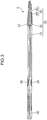
- interdental cleaner group 1 An of interdental cleaner group 1 according to an embodiment of the present invention is described with reference to FIGS. 1 to 10 .
- the interdental cleaner group 1 includes interdental cleaners 2 connected to each other.
- the interdental cleaners 2 adjacent to each other are connected by connecting portions 32.
- Each of the interdental cleaners 2 has a base portion 10 (c.f. FIG. 4 ) made of composite material including synthetic resin and a soft portion 50 (c.f. FIG. 3 ) made of elastomer having hardness lower than that of the composite material.
- the composite material is material including the synthetic resin, glass fiber and titanium dioxide.
- a glass fiber content in the composite material is preferably 10 to 49% by weight, and more preferably 15 to 45% by weight.
- a titanium dioxide content in the composite material is preferably 0.5 to 10% by weight, and more preferably 1 to 5% by weight.
- the glass fiber content is 30% by weight, and the titanium dioxide content is 3% by weight.
- Polypropylene, ABS, polybutylene terephthalate, polycarbonate, polyethylene terephthalate, polystyrene, polyacetal or the like is preferably used as the synthetic resin.
- Styrene elastomer, silicon, olefin elastomer, polyester elastomer or the like is preferably used as the elastomer.
- polypropylene is used as the synthetic resin
- styrene elastomer is used as the elastomer.
- the respective interdental cleaners 2 are manufactured by performing the following first and second steps.
- the base portions (primary molded products) 10 are molded by filling the composite material into a first mold 100 (c.f. FIG. 9 ) having a first space in correspondence to the base portions 10.
- the interdental cleaners (secondary molded products) 2 respectively having the soft portions 50 are manufactured by filling the elastomer into a second mold 200 (c.f. FIG. 10 ) having second spaces configured to form the soft portions 50 under a condition in which the base portions 10 are situated in the second mold 200. Details of the manufacturing method are described later.
- the base portion 10 has a handle portion 20 to be held by fingers and a shaft portion 40 connected to a distal end portion (upper end portion in FIG. 4 ) of the handle portion 20.
- the handle portion 20 has a shape curved at least partially. With regard to the present embodiment, the handle portion 20 is formed in a flat shape.
- the handle portion 20 has a handle main body 22 and a held portion 30.
- the handle main body 22 has a shape which is curved entirely.
- the handle main body 22 has a belly-side edge portion 22a and a back-side edge portion 22b.
- the belly-side edge portion 22a is a portion which is formed on one side (a right side in FIG. 4 ) of the handle main body 22 in a direction orthogonal to an axial direction of the shaft portion 40 to have a curved shape.
- the back-side edge portion 22b is a portion which is formed on the other side (a left side in FIG. 4 ) of the handle main body 22 in the direction orthogonal to the axial direction of the shaft portion 40 to have a curved shape.
- a size of the handle main body 22 in a width direction (a direction connecting the belly-side edge portion 22a and the back-side edge portion 22b) is larger than a thickness of the handle main body 22.
- the handle main body 22 has a base 24, a recessed portion 26 and bulge portions 28.
- the base 24 includes the belly-side edge portion 22a and has a curved shape.
- the recessed portion 26 has a shape recessed from surfaces of the base 24.
- the recessed portion 26 includes the back-side edge portion 22b and has the curved shape.
- the recessed portion 26 is formed on both surfaces of the handle main body 22.
- the recessed portion 26 has a flow path widening region 26A.
- the flow path widening region 26A is a region in which a flow path area for the elastomer at a portion distant by 1 mm from a specific portion of the recessed portion 26 to an opposite side from the shaft portion 40 (downward in FIG. 4 ) is larger by no less than 7% in comparison to a flow path area for the elastomer at the specific portion.
- the flow path widening region 26A is hatched for the purpose of illustration.
- Each of the bulge portions 28 has a shape bulging from a portion of a surface of the recessed portion 26 at a distance from a boundary 25 between the base 24 and the recessed portion 26 (a side surface rising from a proximal end portion of the recessed portion 26).
- Each of the bulge portions 28 is formed at such a position that at least a part of the bulge portion 28 overlaps the flow path widening region 26A of the recessed portion 26.
- a side surface 28a of each of the bulge portions 28 is formed in a shape which is gradually and slightly inclined toward a center of the bulge portion 28 as a distance from the surface of the recessed portion 26 increases.
- the held portion 30 is a part to be held by the second mold 200 in the second step.
- the held portion 30 is connected to the proximal end portion of the handle main body 22.
- a single hole 30h is formed in the held portion 30.
- the hole 30h is used by the second mold 200 to hold the held portion 30. Therefore, as compared with a case in which a plurality of holes are formed in the held portion 30, strength of the second mold 200 is secured.
- the shaft portion 40 is connected to the distal end portion (upper end portion in FIG. 4 ) of the handle portion 20, and has such a shape which allows the shaft portion 40 to be inserted into interdental spaces.
- the shaft portion 40 has a shape extending straight.
- the shaft portion 40 has a sectional area (an area of a section along a plane orthogonal to the axial direction of the shaft portion 40) smaller than a sectional area of the handle portion 20.
- the shaft portion 40 has a substantially circular columnar shape. More specifically, the shaft portion 40 is formed into the shape having an outer diameter gradually and slightly reducing from the proximal end portion toward the distal end portion.
- the shaft portion 40 is formed integrally with the handle portion 20.
- An orientation (attitude) of the shaft portion 40 with respect to the handle portion 20 is set so that an angle between a tangent to the distal end portion of the back-side edge portion 22b and the axial direction of the shaft portion 40 is smaller than an angle between a tangent to the distal end portion of the belly-side edge portion 22a and the axial direction of the shaft portion 40.
- an angle ⁇ (c.f. FIG. 4 ) between a first straight line L1 extending through the center of the shaft portion 40 and a second straight line L2 is preferably set to 10° to 50°.
- the second straight line L2 is a straight line extending through a first midpoint P3 and a second midpoint Q3.
- the first midpoint P3 is a midpoint between an intersection point P1 of a first circle C1 in a first radius (45 mm in the present embodiment), which is centered at the distal end portion 40a of the shaft portion 40, with the belly-side edge portion 22a and an intersection point P2 of the first circle C1 with the back-side edge portion 22b.
- the second midpoint Q3 is a midpoint between an intersection point Q1 of a second circle C2 in a second radius (50 mm in the present embodiment), which is centered at the distal end portion 40a of the shaft portion 40, with the belly-side edge portion 22a and an intersection point Q2 of the second circle C2 with the back-side edge portion 22b.
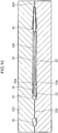
- the soft portion 50 includes a cleaning portion 60 configured to clean interdental spaces, a slip resistance portion 70 and a coupling portion 80.
- the cleaning portion 60 is provided around the shaft portion 40.
- the cleaning portion 60 includes a cleaning portion main body 62 having such a shape as to cover a surface of the shaft portion 40 and brush hairs 64.
- Each of the brush hairs 64 protrudes outward in a direction orthogonal to the axial direction of the shaft portion 40 from an outer peripheral surface of the cleaning portion main body 62 and has an outer shape gradually getting smaller as a distance from the outer peripheral surface of the cleaning portion main body 62 increases.
- each of the brush hairs 64 is formed in a cone shape.
- the slip resistance portion 70 is formed on the surface of the recessed portion 26. As shown in FIGS. 7 and 8 , a surface of the slip resistance portion 70 and the surface of the base 24 are formed to be flush with each other. On the other hand, as shown in FIG. 8 , a surface of each of the bulge portions 28 protrudes a predetermined dimension D (0.15 mm in the present embodiment) from the surface of the slip resistance portion 70 and the surface of the base 24.
- the coupling portion 80 couples the cleaning portion 60 and the slip resistance portion 70. More specifically, the coupling portion 80 couples the cleaning portion 60 and the slip resistance portion 70 on a surface of the distal end portion of the back-side edge portion 22b of the handle main body 22. A sectional area of the coupling portion 80 is smaller than a sectional area of the cleaning portion main body 62 and a sectional area of the slip resistance portion 70.
- FIG. 5 shows a section of the cleaning portion 60 at the proximal end portion
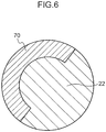
- FIG. 6 shows a section of the coupling portion 80 at the distal end portion.
- an area of the elastomer at the distal end portion of the coupling portion 80 (hereinafter referred to as “coupling portion distal end portion area”) is smaller than an area of the elastomer at the proximal end portion of the cleaning portion 60 (hereinafter referred to as "cleaning portion proximal end portion area").
- a ratio of the coupling portion distal end portion area to the cleaning portion proximal end portion area is preferably between 40% and 90% (inclusive), more preferably between 50% and 85% (inclusive), and yet more preferably between 65% and 85% (inclusive). With regard to the present embodiment, the ratio is set to 70%.
- a method for manufacturing the interdental cleaner 2 is described with reference to FIGS. 9 and 10 .
- the manufacturing method includes the first step and the second step as described above.
- the composite material material including the synthetic resin, the glass fiber and titanium dioxide
- the first mold 100 having the first space in correspondence to the base portions 10 from gates formed at positions in correspondence to the proximal end portions of the base portions 10.
- the base portions 10 are molded.
- the first space is a space having a shape in conformity to the base portions 10 connected to each other by the connecting portions 32.
- the second mold 200 having the spaces for forming the soft portions 50 on the base portions 10 is used.
- the base portions 10 are situated in the second mold 200 at first.
- the base portions 10 are situated in the second mold 200 so that holding portions 202 of the second mold 200 are fitted in the holes 30h in the held portions 30 and that the bulge portions 28 of the base portions 10 are fitted with inner surfaces of the second mold 200.
- each of the bulge portions 28 is guided so as to be fitted with the inner surface of the second mold 200, even if each of the bulge portions 28 is slightly displaced from the position in which the bulge portion 28 is to be fitted with the inner surface of the second mold 200.
- the elastomer is filled into the second mold 200 in this state.
- the elastomer is injected from gates 204 formed at positions of the second mold 200 in correspondence to the distal end portions of the shaft portions 40. In this way, the elastomer flows from peripheries of the shaft portions 40 toward the recessed portions 26.
- the ratio of the coupling portion distal end portion area (the flow path area in the section at the distal end portion for the elastomer around the distal end portion of the back-side edge portion 22b of each of the handle main bodies 22) to the cleaning portion proximal end portion area (the flow path area in the section of the proximal end portion for the elastomer around the proximal end portion of each of the shaft portions 40) is set to 70%, so that it is possible to suppress a very large pressure loss when the elastomer flowing along each of the shaft portions 40 flows through the space in correspondence to each of the coupling portions 80.
- the elastomer flows smoothly from the space around each of the shaft portions 40 toward the space in correspondence to each of the slip resistance portions 70 through the space in correspondence to each of the coupling portions 80. In this way, it is possible to suppress leakage of the elastomer from the second spaces in the second step. Since the ratio is set to 70%, a pressure loss is secured to some extent when the elastomer flows through the space in correspondence to each of the coupling portions 80. In this way, since the elastomer is filled into the spaces in correspondence to the respective brush hairs 64, occurrence of incomplete molding of each of the cleaning portions 60 is suppressed.
- the elastomer collides with the side surface 28a of each of the bulge portions 28 before colliding with the boundary 25 between the base 24 and the recessed portion 26 (the side surface rising from the proximal end portion of the recessed portion 26).
- a flow velocity of the elastomer reduces.
- the elastomer colliding with the side surface 28a of each of the bulge portions 28 flows around the bulge portion 28 and reaches the boundary 25. In this way, the elastomer is prevented from strongly colliding with the boundary 25 between the recessed portion 26 and the base 24.
- the interdental cleaner group 1 including the interdental cleaners 2 is formed.
- the interdental cleaner group 1 it is possible to take an image of the interdental cleaner group 1 to check for insufficient filling (short shot) of the elastomer near the bulge portions 28.
- each of the bulge portions 28 is formed as a floating structure in the slip resistance portion 70 made of the elastomer, so that it is possible to check for the insufficient filling by checking whether the elastomer is filled appropriately to surround each of the bulge portions 28.
- each of the shaft portions 40 and each of the handle main bodies 22 are slightly displaced toward each of the belly-side edge portions 22a with each of the holding portions 202 as a fulcrum due to an injection pressure of the elastomer when the elastomer flows along each of the back-side edge portions 22b in the second step, the space for forming each of the coupling portions 80 (the flow path area for the elastomer) is secured. As a result, the elastomer smoothly flows toward each of the recessed portions 26.
- each of the base portions 10 is molded to have a smaller angle between the tangent to the distal end portion of the back-side edge portion 22b and the axial direction of the shaft portion 40 than an angle between the tangent to the distal end portion of the belly-side edge portion 22a and the axial direction of the shaft portion 40 in the first step, the elastomer further smoothly flows from the periphery of each of the shaft portions 40 toward each of the recessed portions 26 in the second step.
- each of the bulge portions 28 is at least partially situated in each of the flow path widening regions 26A, it is possible to manufacture the interdental cleaners 2 with effective slip resistance functions of the slip resistance portions 70 with suppressing occurrence of jetting near each of the flow path widening regions 26A when the elastomer flows along each of the recessed portions 26 in the second step.
- the jetting may occur near the position of the abrupt increase in the flow path area.
- the composite material filled into the first mold 100 in the first step includes the glass fiber
- the base portions 10 reinforced with the glass fiber are molded.
- Vibration of the base portions 10 when the base portions 10 are situated in the second mold 200 may be suppressed as well.
- the composite material further includes titanium dioxide.
- the reinforcing effect of the glass fiber on the base portions 10 is slightly reduced by the inclusion of titanium dioxide, the bulge portions 28 provided to the base portions 10 suppress the reduction in strength of the handle portions 20 resultant from the inclusion of titanium dioxide and the resultant vibration of the base portions 10 in positioning of the base portions 10 in the second mold 200. It is also possible to mold the white base portions 10 at low cost. It is preferable from a viewpoint of suppressing the reduction in strength that material used to obtain the white base portions 10 is zinc sulfide.
- the handle portion 20 Since the base 24 extends continuously along the belly-side edge portion 22a, the handle portion 20 has higher strength as compared to a case in which a part of the slip resistance portion 70 made of the elastomer is provided along the belly-side edge portion 22a, for example.
- injecting positions of the elastomer in the second step i.e., the positions of the gates 204 are not restricted to those in the aforementioned example.
- the gates 204 may be provided at positions in correspondence to portions of the base portions 10 between the shaft portions 40 and the bulge portions 28. In this way, the elastomer flowing along each of the recessed portions 26 becomes likely to collide with the side surface 28a of each of the bulge portions 28, so that occurrence of so-called jetting is suppressed near each of the bulge portions 28.
- the recessed portion 26 and the slip resistance portion 70 may be provided to only one surface of the handle main body 22.
- the first mold 100 and the second mold 200 it is possible to use a mold including a lower mold and an upper mold for forming a first space and a second space with the lower mold, the lower mold including a base mold and a rotatable mold.
- the rotatable mold is a mold which is rotatable with respect to the base mold with holding the held portion 30 of the base portion 10.
- the base mold has portions configured to form a space in correspondence to the handle main body 22 and the shaft portion 40, and a space in correspondence to the soft portion 50.
- the rotatable mold has a portion configured to form a space in correspondence to the held portion 30.
- composite material is filled into the first space formed between the lower mold and the upper mold in the first step.
- the upper mold separates from the lower mold upward whereas the rotatable mold separates from the base mold upward with holding the held portion 30 and rotates 180° in the position, and is displaced toward the base mold again.
- the base portion 10 is situated in the space in correspondence to the soft portion 50 (the region below the second space) in the lower mold .
- the upper mold comes into contact with the lower mold to form the first space and the second space.
- elastomer is filled into the second space.
- the composite material is filled into the first space (the first step is performed).
Landscapes
- Engineering & Computer Science (AREA)
- Manufacturing & Machinery (AREA)
- Mechanical Engineering (AREA)
- Health & Medical Sciences (AREA)
- Chemical & Material Sciences (AREA)
- Materials Engineering (AREA)
- Epidemiology (AREA)
- Life Sciences & Earth Sciences (AREA)
- Animal Behavior & Ethology (AREA)
- General Health & Medical Sciences (AREA)
- Public Health (AREA)
- Veterinary Medicine (AREA)
- Dentistry (AREA)
- Moulds For Moulding Plastics Or The Like (AREA)
- Injection Moulding Of Plastics Or The Like (AREA)
Claims (8)
- Procédé de fabrication d'un dispositif de nettoyage interdentaire (2), le procédé comprenant:une première étape de moulage d'une partie de base (10) en versant un matériau composite incluant une résine synthétique dans un premier moule (100) présentant un premier espace en correspondance avec la partie de base qui inclut une partie de poignée (20) présentant une forme qui est au moins partiellement incurvée et une partie de tige (40) connectée à une partie d'extrémité distale de la partie de poignée, la partie de tige présentant une aire de section plus petite qu'une aire de section de la partie de poignée et une forme qui permet à la partie de tige d'être insérée dans un espace interdentaire ; etune seconde étape de formation d'une partie de nettoyage (60) configurée pour nettoyer l'espace interdentaire, une partie anti-glissement (70) et une partie de liaison (80) configurée pour lier la partie de nettoyage et la partie anti-glissement en versant un élastomère dans un second moule (200) à partir d'un côté d'une partie d'extrémité distale de la partie de tige dans une condition dans laquelle la partie de base est située dans le second moule, le second moule présentant un second espace configuré pour former la partie de nettoyage autour de la partie de tige, la partie anti-glissement sur une surface de la partie de poignée, et la partie de liaison sur une surface de la partie de poignée,dans lequel ce qui est utilisé comme second moule dans la seconde étape présente un rapport d'une aire de passage d'écoulement d'élastomère dans une section du second espace autour de la partie d'extrémité distale de la partie de poignée à une aire de passage d'écoulement d'élastomère dans une section du second espace autour d'une partie d'extrémité proximale de la partie de tige, le rapport n'étant pas inférieur à 40%.
- Procédé de fabrication d'un dispositif de nettoyage interdentaire selon la revendication 1,
dans lequel ce qui est utilisé comme second moule dans la seconde étape présente le rapport qui n'est pas supérieur à 90 %. - Procédé de fabrication d'un dispositif de nettoyage interdentaire selon la revendication 1 ou 2,dans lequel dans la première étape, ce qui est moulé présente la partie de poignée incluant une base (24) et une partie évidée (26) présentant une forme évidée à partir d'une surface de la base, la partie de poignée incluant une partie de bord côté dos (22b),qui est formée sur un premier côté dans une direction orthogonale à une direction axiale de la partie de tige pour présenter une forme incurvée de sorte que la partie évidée est formée à une position incluant au moins une partie de la partie de bord côté dos, et une partie de bord côté ventre (22a),qui est formée sur un autre côté pour présenter une forme incurvée de sorte que la base est formée à une position incluant au moins une partie de la partie de bord côté ventre, un angle entre une tangente à une partie d'extrémité distale de la partie de bord côté dos et la direction axiale de la partie de tige étant inférieur à un angle entre une tangente à une partie d'extrémité distale de la partie de bord côté ventre et la direction axiale de la partie de tige, etdans lequel dans la seconde étape, l'élastomère est versé dans le second moule de sorte que l'élastomère s'écoule le long de la partie de tige et de la partie évidée.
- Procédé de fabrication d'un dispositif de nettoyage interdentaire selon la revendication 3,
dans lequel dans la première étape, ce qui est moulé comme partie de base inclut la base présentant une forme s'étendant en continu le long de la partie de bord côté ventre. - Procédé de fabrication d'un dispositif de nettoyage interdentaire selon l'une quelconque des revendications 3 ou 4,
dans lequel dans la première étape, ce qui est moulé comme partie de poignée inclut en outre une partie bombée (28) qui est bombée à partir d'une partie d'une surface de la partie évidée à une distance d'une limite entre la base et la partie évidée. - Procédé de fabrication d'un dispositif de nettoyage interdentaire selon la revendication 5,
dans lequel dans la première étape, ce qui est moulé comme la partie évidée inclut une région d'élargissement de passage d'écoulement (26A) dans laquelle une aire de passage d'écoulement d'élastomère au niveau d'une partie distante de 1 mm d'une partie spécifique de la partie évidée vers un côté opposé à la partie de tige est plus grande d'au moins 7 % en comparaison avec une aire de passage d'écoulement d'élastomère au niveau de la partie spécifique, et la partie bombée qui est au moins partiellement située dans la région d'élargissement de passage d'écoulement. - Procédé de fabrication d'un dispositif de nettoyage interdentaire selon l'une quelconque des revendications 1 à 6,
dans lequel dans la première étape, le matériau composite incluant la résine synthétique et une fibre de verre est versé dans le premier moule. - Procédé de fabrication d'un dispositif de nettoyage interdentaire selon la revendication 7,
dans lequel dans la première étape, le matériau composite incluant en outre du dioxyde de titane est versé dans le premier moule.
Applications Claiming Priority (2)
| Application Number | Priority Date | Filing Date | Title |
|---|---|---|---|
| JP2016256517A JP6752139B2 (ja) | 2016-12-28 | 2016-12-28 | 歯間清掃具の製造方法 |
| PCT/JP2017/047362 WO2018124302A1 (fr) | 2016-12-28 | 2017-12-28 | Procédé de production d'outil de nettoyage interdentaire |
Publications (3)
| Publication Number | Publication Date |
|---|---|
| EP3563798A1 EP3563798A1 (fr) | 2019-11-06 |
| EP3563798A4 EP3563798A4 (fr) | 2020-09-02 |
| EP3563798B1 true EP3563798B1 (fr) | 2021-10-20 |
Family
ID=62709498
Family Applications (1)
| Application Number | Title | Priority Date | Filing Date |
|---|---|---|---|
| EP17888780.8A Active EP3563798B1 (fr) | 2016-12-28 | 2017-12-28 | Procédé de production d'outil de nettoyage interdentaire |
Country Status (5)
| Country | Link |
|---|---|
| US (1) | US11351705B2 (fr) |
| EP (1) | EP3563798B1 (fr) |
| JP (1) | JP6752139B2 (fr) |
| CN (1) | CN110167478B (fr) |
| WO (1) | WO2018124302A1 (fr) |
Families Citing this family (4)
| Publication number | Priority date | Publication date | Assignee | Title |
|---|---|---|---|---|
| USD884279S1 (en) * | 2018-05-17 | 2020-05-12 | M+C Schiffer Gmbh | Oral care device |
| JP7652528B2 (ja) | 2018-12-28 | 2025-03-27 | 小林製薬株式会社 | 歯間清掃具 |
| JP2020103851A (ja) | 2018-12-28 | 2020-07-09 | 小林製薬株式会社 | 歯間清掃具 |
| JP7417353B2 (ja) | 2018-12-28 | 2024-01-18 | 小林製薬株式会社 | 歯間清掃具の製造方法 |
Family Cites Families (18)
| Publication number | Priority date | Publication date | Assignee | Title |
|---|---|---|---|---|
| JPH02151425A (ja) * | 1988-12-03 | 1990-06-11 | Bando Chem Ind Ltd | 歯付き伝導ベルトの射出成形用金型 |
| DE19857296A1 (de) * | 1998-12-14 | 2000-06-15 | Hauni Maschinenbau Ag | Verfahren und Vorrichtung zum Bilden eines Tabakstrangs |
| DE10033256A1 (de) * | 2000-07-10 | 2002-01-24 | Coronet Werke Gmbh | Verfahren und Vorrichtung zur Herstellung von Borstenwaren sowie Borstenware |
| DE10065517A1 (de) | 2000-12-28 | 2002-07-04 | Trisa Holding Ag Triengen | Verfahren zur Herstellung einer Zahnbürste |
| US20130273502A1 (en) * | 2008-03-24 | 2013-10-17 | Richard J. Shaw | Dental probe, a method of forming the probe and a method of using the probe |
| US9468510B2 (en) * | 2008-03-24 | 2016-10-18 | Richard J. Shaw | Floss device, a method of forming the floss device and a method of using the floss device |
| US8549691B2 (en) * | 2009-12-18 | 2013-10-08 | Colgate-Palmolive Company | Oral care implement having multi-component handle |
| JP5836610B2 (ja) | 2011-03-04 | 2015-12-24 | キヤノン株式会社 | プラスチック光学部材及びその製造方法 |
| EP2857167B1 (fr) * | 2012-05-24 | 2023-03-15 | Sunstar Suisse SA | Procédé de fabrication d'un outil de nettoyage interdentaire et outil de nettoyage interdentaire |
| EP2922680A2 (fr) | 2012-11-21 | 2015-09-30 | iMFLUX Inc. | Canal de coulée de taille réduite pour un système de moulage par injection |
| ES2605394T3 (es) * | 2014-03-06 | 2017-03-14 | Tepe Munhygienprodukter Ab | Limpiador interdental |
| CN107106272B (zh) * | 2014-11-11 | 2019-06-14 | 盛势达(瑞士)有限公司 | 牙缝清洁工具的制造方法 |
| EP3305243B1 (fr) * | 2015-06-08 | 2024-12-11 | Sunstar Suisse SA | Outil de nettoyage interdentaire |
| JP6625374B2 (ja) * | 2015-08-28 | 2019-12-25 | 小林製薬株式会社 | 歯間清掃具及び歯間清掃具の製造方法 |
| JP6639875B2 (ja) * | 2015-11-17 | 2020-02-05 | 小林製薬株式会社 | 歯間清掃具 |
| JP6730797B2 (ja) * | 2015-11-17 | 2020-07-29 | 小林製薬株式会社 | 歯間清掃具群 |
| JP6292246B2 (ja) * | 2016-03-07 | 2018-03-14 | サンスター株式会社 | 歯間清掃具 |
| JP6387386B2 (ja) * | 2016-12-28 | 2018-09-05 | 小林製薬株式会社 | 歯間清掃具の製造方法 |
-
2016
- 2016-12-28 JP JP2016256517A patent/JP6752139B2/ja active Active
-
2017
- 2017-12-28 CN CN201780081366.8A patent/CN110167478B/zh not_active Expired - Fee Related
- 2017-12-28 EP EP17888780.8A patent/EP3563798B1/fr active Active
- 2017-12-28 WO PCT/JP2017/047362 patent/WO2018124302A1/fr not_active Ceased
- 2017-12-28 US US16/472,872 patent/US11351705B2/en active Active
Also Published As
| Publication number | Publication date |
|---|---|
| CN110167478A (zh) | 2019-08-23 |
| EP3563798A4 (fr) | 2020-09-02 |
| JP2018108148A (ja) | 2018-07-12 |
| EP3563798A1 (fr) | 2019-11-06 |
| US20200189159A1 (en) | 2020-06-18 |
| JP6752139B2 (ja) | 2020-09-09 |
| US11351705B2 (en) | 2022-06-07 |
| CN110167478B (zh) | 2021-06-11 |
| WO2018124302A1 (fr) | 2018-07-05 |
Similar Documents
| Publication | Publication Date | Title |
|---|---|---|
| EP3563797B1 (fr) | Procédé de fabrication d'un dispositif de nettoyage interdentaire | |
| EP3563798B1 (fr) | Procédé de production d'outil de nettoyage interdentaire | |
| JP6409825B2 (ja) | 歯間清掃具の製造方法 | |
| JP6262288B2 (ja) | 歯間清掃具の製造方法 | |
| CN107920877B (zh) | 基部、齿间清洁具以及齿间清洁具的制造方法 | |
| US8408891B2 (en) | Golf ball mold and golf ball manufacturing method | |
| US20120118850A1 (en) | Multilayered cosmetic container | |
| US11633269B2 (en) | Method of manufacturing inter-dental cleaning tool | |
| JP2018108483A (ja) | 歯間清掃具の製造方法 | |
| EP3785663B1 (fr) | Outil de nettoyage interdentaire | |
| JP4929245B2 (ja) | 工具類のグリップ | |
| HK40006294A (zh) | 齿间清洁具的制造方法 | |
| HK40006295A (en) | Method for producing interdental cleaning tool | |
| HK40006295B (en) | Method for producing interdental cleaning tool | |
| HK40006294B (zh) | 齿间清洁具的制造方法 | |
| JP7105124B2 (ja) | 二色成形物の製造方法および二色成形物 | |
| US11585468B2 (en) | Thermoplastic elastomeric bellow duct | |
| US20240151269A1 (en) | Cage and ball bearing | |
| JP6976831B2 (ja) | 歯間清掃具の製造方法 |
Legal Events
| Date | Code | Title | Description |
|---|---|---|---|
| STAA | Information on the status of an ep patent application or granted ep patent |
Free format text: STATUS: THE INTERNATIONAL PUBLICATION HAS BEEN MADE |
|
| PUAI | Public reference made under article 153(3) epc to a published international application that has entered the european phase |
Free format text: ORIGINAL CODE: 0009012 |
|
| STAA | Information on the status of an ep patent application or granted ep patent |
Free format text: STATUS: REQUEST FOR EXAMINATION WAS MADE |
|
| 17P | Request for examination filed |
Effective date: 20190628 |
|
| AK | Designated contracting states |
Kind code of ref document: A1 Designated state(s): AL AT BE BG CH CY CZ DE DK EE ES FI FR GB GR HR HU IE IS IT LI LT LU LV MC MK MT NL NO PL PT RO RS SE SI SK SM TR |
|
| AX | Request for extension of the european patent |
Extension state: BA ME |
|
| DAV | Request for validation of the european patent (deleted) | ||
| DAX | Request for extension of the european patent (deleted) | ||
| A4 | Supplementary search report drawn up and despatched |
Effective date: 20200803 |
|
| RIC1 | Information provided on ipc code assigned before grant |
Ipc: A61C 15/02 20060101AFI20200728BHEP |
|
| GRAP | Despatch of communication of intention to grant a patent |
Free format text: ORIGINAL CODE: EPIDOSNIGR1 |
|
| STAA | Information on the status of an ep patent application or granted ep patent |
Free format text: STATUS: GRANT OF PATENT IS INTENDED |
|
| INTG | Intention to grant announced |
Effective date: 20210503 |
|
| GRAS | Grant fee paid |
Free format text: ORIGINAL CODE: EPIDOSNIGR3 |
|
| GRAA | (expected) grant |
Free format text: ORIGINAL CODE: 0009210 |
|
| STAA | Information on the status of an ep patent application or granted ep patent |
Free format text: STATUS: THE PATENT HAS BEEN GRANTED |
|
| AK | Designated contracting states |
Kind code of ref document: B1 Designated state(s): AL AT BE BG CH CY CZ DE DK EE ES FI FR GB GR HR HU IE IS IT LI LT LU LV MC MK MT NL NO PL PT RO RS SE SI SK SM TR |
|
| REG | Reference to a national code |
Ref country code: GB Ref legal event code: FG4D |
|
| REG | Reference to a national code |
Ref country code: CH Ref legal event code: EP |
|
| REG | Reference to a national code |
Ref country code: IE Ref legal event code: FG4D |
|
| REG | Reference to a national code |
Ref country code: DE Ref legal event code: R096 Ref document number: 602017048091 Country of ref document: DE |
|
| REG | Reference to a national code |
Ref country code: AT Ref legal event code: REF Ref document number: 1439286 Country of ref document: AT Kind code of ref document: T Effective date: 20211115 |
|
| REG | Reference to a national code |
Ref country code: LT Ref legal event code: MG9D |
|
| REG | Reference to a national code |
Ref country code: NL Ref legal event code: MP Effective date: 20211020 |
|
| REG | Reference to a national code |
Ref country code: AT Ref legal event code: MK05 Ref document number: 1439286 Country of ref document: AT Kind code of ref document: T Effective date: 20211020 |
|
| PG25 | Lapsed in a contracting state [announced via postgrant information from national office to epo] |
Ref country code: RS Free format text: LAPSE BECAUSE OF FAILURE TO SUBMIT A TRANSLATION OF THE DESCRIPTION OR TO PAY THE FEE WITHIN THE PRESCRIBED TIME-LIMIT Effective date: 20211020 Ref country code: LT Free format text: LAPSE BECAUSE OF FAILURE TO SUBMIT A TRANSLATION OF THE DESCRIPTION OR TO PAY THE FEE WITHIN THE PRESCRIBED TIME-LIMIT Effective date: 20211020 Ref country code: FI Free format text: LAPSE BECAUSE OF FAILURE TO SUBMIT A TRANSLATION OF THE DESCRIPTION OR TO PAY THE FEE WITHIN THE PRESCRIBED TIME-LIMIT Effective date: 20211020 Ref country code: BG Free format text: LAPSE BECAUSE OF FAILURE TO SUBMIT A TRANSLATION OF THE DESCRIPTION OR TO PAY THE FEE WITHIN THE PRESCRIBED TIME-LIMIT Effective date: 20220120 Ref country code: AT Free format text: LAPSE BECAUSE OF FAILURE TO SUBMIT A TRANSLATION OF THE DESCRIPTION OR TO PAY THE FEE WITHIN THE PRESCRIBED TIME-LIMIT Effective date: 20211020 |
|
| PG25 | Lapsed in a contracting state [announced via postgrant information from national office to epo] |
Ref country code: IS Free format text: LAPSE BECAUSE OF FAILURE TO SUBMIT A TRANSLATION OF THE DESCRIPTION OR TO PAY THE FEE WITHIN THE PRESCRIBED TIME-LIMIT Effective date: 20220220 Ref country code: SE Free format text: LAPSE BECAUSE OF FAILURE TO SUBMIT A TRANSLATION OF THE DESCRIPTION OR TO PAY THE FEE WITHIN THE PRESCRIBED TIME-LIMIT Effective date: 20211020 Ref country code: PT Free format text: LAPSE BECAUSE OF FAILURE TO SUBMIT A TRANSLATION OF THE DESCRIPTION OR TO PAY THE FEE WITHIN THE PRESCRIBED TIME-LIMIT Effective date: 20220221 Ref country code: PL Free format text: LAPSE BECAUSE OF FAILURE TO SUBMIT A TRANSLATION OF THE DESCRIPTION OR TO PAY THE FEE WITHIN THE PRESCRIBED TIME-LIMIT Effective date: 20211020 Ref country code: NO Free format text: LAPSE BECAUSE OF FAILURE TO SUBMIT A TRANSLATION OF THE DESCRIPTION OR TO PAY THE FEE WITHIN THE PRESCRIBED TIME-LIMIT Effective date: 20220120 Ref country code: NL Free format text: LAPSE BECAUSE OF FAILURE TO SUBMIT A TRANSLATION OF THE DESCRIPTION OR TO PAY THE FEE WITHIN THE PRESCRIBED TIME-LIMIT Effective date: 20211020 Ref country code: LV Free format text: LAPSE BECAUSE OF FAILURE TO SUBMIT A TRANSLATION OF THE DESCRIPTION OR TO PAY THE FEE WITHIN THE PRESCRIBED TIME-LIMIT Effective date: 20211020 Ref country code: HR Free format text: LAPSE BECAUSE OF FAILURE TO SUBMIT A TRANSLATION OF THE DESCRIPTION OR TO PAY THE FEE WITHIN THE PRESCRIBED TIME-LIMIT Effective date: 20211020 Ref country code: GR Free format text: LAPSE BECAUSE OF FAILURE TO SUBMIT A TRANSLATION OF THE DESCRIPTION OR TO PAY THE FEE WITHIN THE PRESCRIBED TIME-LIMIT Effective date: 20220121 Ref country code: ES Free format text: LAPSE BECAUSE OF FAILURE TO SUBMIT A TRANSLATION OF THE DESCRIPTION OR TO PAY THE FEE WITHIN THE PRESCRIBED TIME-LIMIT Effective date: 20211020 |
|
| REG | Reference to a national code |
Ref country code: DE Ref legal event code: R097 Ref document number: 602017048091 Country of ref document: DE |
|
| PG25 | Lapsed in a contracting state [announced via postgrant information from national office to epo] |
Ref country code: SM Free format text: LAPSE BECAUSE OF FAILURE TO SUBMIT A TRANSLATION OF THE DESCRIPTION OR TO PAY THE FEE WITHIN THE PRESCRIBED TIME-LIMIT Effective date: 20211020 Ref country code: SK Free format text: LAPSE BECAUSE OF FAILURE TO SUBMIT A TRANSLATION OF THE DESCRIPTION OR TO PAY THE FEE WITHIN THE PRESCRIBED TIME-LIMIT Effective date: 20211020 Ref country code: RO Free format text: LAPSE BECAUSE OF FAILURE TO SUBMIT A TRANSLATION OF THE DESCRIPTION OR TO PAY THE FEE WITHIN THE PRESCRIBED TIME-LIMIT Effective date: 20211020 Ref country code: MC Free format text: LAPSE BECAUSE OF FAILURE TO SUBMIT A TRANSLATION OF THE DESCRIPTION OR TO PAY THE FEE WITHIN THE PRESCRIBED TIME-LIMIT Effective date: 20211020 Ref country code: EE Free format text: LAPSE BECAUSE OF FAILURE TO SUBMIT A TRANSLATION OF THE DESCRIPTION OR TO PAY THE FEE WITHIN THE PRESCRIBED TIME-LIMIT Effective date: 20211020 Ref country code: DK Free format text: LAPSE BECAUSE OF FAILURE TO SUBMIT A TRANSLATION OF THE DESCRIPTION OR TO PAY THE FEE WITHIN THE PRESCRIBED TIME-LIMIT Effective date: 20211020 Ref country code: CZ Free format text: LAPSE BECAUSE OF FAILURE TO SUBMIT A TRANSLATION OF THE DESCRIPTION OR TO PAY THE FEE WITHIN THE PRESCRIBED TIME-LIMIT Effective date: 20211020 |
|
| PLBE | No opposition filed within time limit |
Free format text: ORIGINAL CODE: 0009261 |
|
| STAA | Information on the status of an ep patent application or granted ep patent |
Free format text: STATUS: NO OPPOSITION FILED WITHIN TIME LIMIT |
|
| REG | Reference to a national code |
Ref country code: BE Ref legal event code: MM Effective date: 20211231 |
|
| 26N | No opposition filed |
Effective date: 20220721 |
|
| GBPC | Gb: european patent ceased through non-payment of renewal fee |
Effective date: 20220120 |
|
| PG25 | Lapsed in a contracting state [announced via postgrant information from national office to epo] |
Ref country code: LU Free format text: LAPSE BECAUSE OF NON-PAYMENT OF DUE FEES Effective date: 20211228 Ref country code: IE Free format text: LAPSE BECAUSE OF NON-PAYMENT OF DUE FEES Effective date: 20211228 Ref country code: GB Free format text: LAPSE BECAUSE OF NON-PAYMENT OF DUE FEES Effective date: 20220120 Ref country code: AL Free format text: LAPSE BECAUSE OF FAILURE TO SUBMIT A TRANSLATION OF THE DESCRIPTION OR TO PAY THE FEE WITHIN THE PRESCRIBED TIME-LIMIT Effective date: 20211020 |
|
| PG25 | Lapsed in a contracting state [announced via postgrant information from national office to epo] |
Ref country code: SI Free format text: LAPSE BECAUSE OF FAILURE TO SUBMIT A TRANSLATION OF THE DESCRIPTION OR TO PAY THE FEE WITHIN THE PRESCRIBED TIME-LIMIT Effective date: 20211020 Ref country code: BE Free format text: LAPSE BECAUSE OF NON-PAYMENT OF DUE FEES Effective date: 20211231 |
|
| PG25 | Lapsed in a contracting state [announced via postgrant information from national office to epo] |
Ref country code: IT Free format text: LAPSE BECAUSE OF FAILURE TO SUBMIT A TRANSLATION OF THE DESCRIPTION OR TO PAY THE FEE WITHIN THE PRESCRIBED TIME-LIMIT Effective date: 20211020 |
|
| P01 | Opt-out of the competence of the unified patent court (upc) registered |
Effective date: 20230511 |
|
| PG25 | Lapsed in a contracting state [announced via postgrant information from national office to epo] |
Ref country code: CY Free format text: LAPSE BECAUSE OF FAILURE TO SUBMIT A TRANSLATION OF THE DESCRIPTION OR TO PAY THE FEE WITHIN THE PRESCRIBED TIME-LIMIT Effective date: 20211020 |
|
| PG25 | Lapsed in a contracting state [announced via postgrant information from national office to epo] |
Ref country code: HU Free format text: LAPSE BECAUSE OF FAILURE TO SUBMIT A TRANSLATION OF THE DESCRIPTION OR TO PAY THE FEE WITHIN THE PRESCRIBED TIME-LIMIT; INVALID AB INITIO Effective date: 20171228 |
|
| PG25 | Lapsed in a contracting state [announced via postgrant information from national office to epo] |
Ref country code: MK Free format text: LAPSE BECAUSE OF FAILURE TO SUBMIT A TRANSLATION OF THE DESCRIPTION OR TO PAY THE FEE WITHIN THE PRESCRIBED TIME-LIMIT Effective date: 20211020 |
|
| PG25 | Lapsed in a contracting state [announced via postgrant information from national office to epo] |
Ref country code: MT Free format text: LAPSE BECAUSE OF FAILURE TO SUBMIT A TRANSLATION OF THE DESCRIPTION OR TO PAY THE FEE WITHIN THE PRESCRIBED TIME-LIMIT Effective date: 20211020 |
|
| PGFP | Annual fee paid to national office [announced via postgrant information from national office to epo] |
Ref country code: CH Payment date: 20250101 Year of fee payment: 8 |
|
| PG25 | Lapsed in a contracting state [announced via postgrant information from national office to epo] |
Ref country code: TR Free format text: LAPSE BECAUSE OF FAILURE TO SUBMIT A TRANSLATION OF THE DESCRIPTION OR TO PAY THE FEE WITHIN THE PRESCRIBED TIME-LIMIT Effective date: 20211020 |
|
| REG | Reference to a national code |
Ref country code: CH Ref legal event code: U11 Free format text: ST27 STATUS EVENT CODE: U-0-0-U10-U11 (AS PROVIDED BY THE NATIONAL OFFICE) Effective date: 20260101 |
|
| PGFP | Annual fee paid to national office [announced via postgrant information from national office to epo] |
Ref country code: DE Payment date: 20251211 Year of fee payment: 9 |
|
| PGFP | Annual fee paid to national office [announced via postgrant information from national office to epo] |
Ref country code: FR Payment date: 20251229 Year of fee payment: 9 |