EP3563796A1 - System aus dentalrestaurationsteil(en) und kühlvorrichtung sowie verfahren - Google Patents
System aus dentalrestaurationsteil(en) und kühlvorrichtung sowie verfahren Download PDFInfo
- Publication number
- EP3563796A1 EP3563796A1 EP18170105.3A EP18170105A EP3563796A1 EP 3563796 A1 EP3563796 A1 EP 3563796A1 EP 18170105 A EP18170105 A EP 18170105A EP 3563796 A1 EP3563796 A1 EP 3563796A1
- Authority
- EP
- European Patent Office
- Prior art keywords
- dental restoration
- restoration part
- cooling
- heat sink
- heat sinks
- Prior art date
- Legal status (The legal status is an assumption and is not a legal conclusion. Google has not performed a legal analysis and makes no representation as to the accuracy of the status listed.)
- Granted
Links
Images

Classifications
-
- F—MECHANICAL ENGINEERING; LIGHTING; HEATING; WEAPONS; BLASTING
- F27—FURNACES; KILNS; OVENS; RETORTS
- F27D—DETAILS OR ACCESSORIES OF FURNACES, KILNS, OVENS OR RETORTS, IN SO FAR AS THEY ARE OF KINDS OCCURRING IN MORE THAN ONE KIND OF FURNACE
- F27D9/00—Cooling of furnaces or of charges therein
-
- A—HUMAN NECESSITIES
- A61—MEDICAL OR VETERINARY SCIENCE; HYGIENE
- A61C—DENTISTRY; APPARATUS OR METHODS FOR ORAL OR DENTAL HYGIENE
- A61C13/00—Dental prostheses; Making same
- A61C13/0003—Making bridge-work, inlays, implants or the like
- A61C13/0006—Production methods
-
- A—HUMAN NECESSITIES
- A61—MEDICAL OR VETERINARY SCIENCE; HYGIENE
- A61C—DENTISTRY; APPARATUS OR METHODS FOR ORAL OR DENTAL HYGIENE
- A61C13/00—Dental prostheses; Making same
-
- A—HUMAN NECESSITIES
- A61—MEDICAL OR VETERINARY SCIENCE; HYGIENE
- A61C—DENTISTRY; APPARATUS OR METHODS FOR ORAL OR DENTAL HYGIENE
- A61C13/00—Dental prostheses; Making same
- A61C13/08—Artificial teeth; Making same
- A61C13/083—Porcelain or ceramic teeth
-
- F—MECHANICAL ENGINEERING; LIGHTING; HEATING; WEAPONS; BLASTING
- F25—REFRIGERATION OR COOLING; COMBINED HEATING AND REFRIGERATION SYSTEMS; HEAT PUMP SYSTEMS; MANUFACTURE OR STORAGE OF ICE; LIQUEFACTION SOLIDIFICATION OF GASES
- F25D—REFRIGERATORS; COLD ROOMS; ICE-BOXES; COOLING OR FREEZING APPARATUS NOT OTHERWISE PROVIDED FOR
- F25D3/00—Devices using other cold materials; Devices using cold-storage bodies
-
- F—MECHANICAL ENGINEERING; LIGHTING; HEATING; WEAPONS; BLASTING
- F27—FURNACES; KILNS; OVENS; RETORTS
- F27B—FURNACES, KILNS, OVENS OR RETORTS IN GENERAL; OPEN SINTERING OR LIKE APPARATUS
- F27B17/00—Furnaces of a kind not covered by any of groups F27B1/00 - F27B15/00
- F27B17/02—Furnaces of a kind not covered by any of groups F27B1/00 - F27B15/00 specially designed for laboratory use
- F27B17/025—Furnaces of a kind not covered by any of groups F27B1/00 - F27B15/00 specially designed for laboratory use for dental workpieces
-
- F—MECHANICAL ENGINEERING; LIGHTING; HEATING; WEAPONS; BLASTING
- F27—FURNACES; KILNS; OVENS; RETORTS
- F27D—DETAILS OR ACCESSORIES OF FURNACES, KILNS, OVENS OR RETORTS, IN SO FAR AS THEY ARE OF KINDS OCCURRING IN MORE THAN ONE KIND OF FURNACE
- F27D19/00—Arrangements of controlling devices
-
- F—MECHANICAL ENGINEERING; LIGHTING; HEATING; WEAPONS; BLASTING
- F27—FURNACES; KILNS; OVENS; RETORTS
- F27D—DETAILS OR ACCESSORIES OF FURNACES, KILNS, OVENS OR RETORTS, IN SO FAR AS THEY ARE OF KINDS OCCURRING IN MORE THAN ONE KIND OF FURNACE
- F27D9/00—Cooling of furnaces or of charges therein
- F27D2009/007—Cooling of charges therein
- F27D2009/0091—Cooling of charges therein in a fluidised bed of cooling elements
Definitions
- the invention relates to a system comprising a dental restoration part and a cooling device, according to the preamble of claims 1 and 2, and an associated method, according to the preamble of claims 17, 18 and 19.
- dental restoration parts are made under heat treatment.
- dental ovens which have a combustion chamber in which usually several dental restoration parts can be fired at the same time.
- the dental restoration parts are often made of special dental ceramics such as lithium disilicate or zirconium oxide and require a special firing curve to provide the desired properties.
- zirconium oxide required cycle times of several hours, for example eight hours.
- Microcracks are particularly critical because they are often overlooked. In the microcracks bacteria can accumulate in the patient's mouth, which can lead to infections. Essentially, microcracks in ceramic restorations have a negative effect on long-term stability and mechanical properties over the wearing period.
- Another problem is the breaking strength, especially in complex designed dental restorations.
- a cooling rate is typically selected which ensures that there are no cracks and no residual stresses, in particular tensile compressive stresses.
- the cooling is often carried out so that a combustion hood, in which the combustion chamber is formed, is raised. This has the advantage that the footprint on which the dental restoration parts lie is not shaken by an avoidable movement.
- the incoming ambient air then causes the dental restoration part to cool.
- An improved solution for preventing asymmetric cooling can be the DE 195 429 841 C1 remove.
- a firing cap is not only swung up, but first lifted vertically and then pivoted first. This allows a uniform access of air from all sides, and thus a thermo-voltage-free cooling. To avoid thermal stresses, the firing hood is initially only slightly raised, and then stronger, so that no too large Delta-T is formed.
- the invention has for its object to provide a system of a dental restoration part or more dental restoration parts and a cooling device and an associated method according to the preambles of claims 1, 2, 17, 18, 19, which are improved in terms of cooling efficiency without thermal Tensions would arise.
- the dental restoration part (s) in the bed of cooling bodies are in contact with them and so cooling can take place via a solid-state heat conduction.
- the dental restoration part or the dental restoration parts is or are surrounded on all sides by heat sinks. This means that a one-sided cooling is excluded as with the use of a blower. Rather, the dental restoration part is cooled uniformly from all sides.
- Also important according to the invention is the relative movement between the dental restoration part and the heat sinks via a movement device. This makes it possible to bring ever new and therefore cooler heatsink to the dental restoration part.
- the heated heatsinks are removed or mixed in the heap or bed for the dental restoration parts.
- the relative movement between the dental restoration part and the heat sinks can be realized in any suitable manner by the movement device.
- the dental restoration part can be held in a stream of heat sinks. In this case, it is favorable if the dental restoration part is also rotated by the current so that new sides of the dental restoration part always come into contact with the flow of the cooling bodies.
- Very hot dental restoration parts can thus initially cool, for example, in the ambient air for a short time. At this time, the Delta-T is very large, so that a convection cooling is still effective.
- the dental restoration part can be allowed to cool zirconia after sintering and opening the furnace head of about 1200 degrees, or lithium disilicate of about 700 degrees. In both cases, the solidification of the ceramic has progressed so far that a movement of the dental restoration part is not critical.
- the dental restoration part is brought into contact with the cooling bodies as bulk material, or the bulk material is supplied to the dental restoration parts.
- the present invention effective and uniform contact cooling or heat conduction cooling is set in motion.
- dental restoration part all possible types of dental restoration parts are to be subsumed in the singular or in the plural: for example, teeth which are produced based on standard specifications or those which are specially adapted to the patient. Also inlays, onlays, bridges, crowns, partial crowns, abutments and abutment crowns and dental arches, partial dental arches, partial dentures, full dentures and any other heat-treated dental products.
- the materials used for the dental restoration parts include ceramics, composites and metals and metal alloys, as well as any other dental materials that require heat treatment.
- Any suitable direction of movement can be used to provide the relative movement.
- This includes, for example, a device with a trickle opening.
- the trickle opening can be located above, below or to the side of the dental restoration part and allow the heat sink to pass as bulk material, in a predetermined flow rate.
- the flow rate can also be adjustable, for example by the size or shape of the trickle opening is adjusted.
- the trickle opening can be provided both upstream and downstream of the dental restoration part.
- the dental restoration part may be held in a kind of grate or sieve which is shaped so that the movement of the heat sink results in movement of the dental restoration part.
- the flow of the heat sink with its main flow direction can be guided slightly laterally of the middle of the dental restoration part, so that the dental restoration part is also rotated by the friction of the heat sink.
- the heat sinks can also be moved in a sieve drum in the manner of a laundry drum together with the dental restoration part. Their sieve openings can be chosen so small that the heat sinks pass through, whereas the dental restoration part does not.
- the heat sinks are preferably abrasion-resistant and dust-free, so that no contamination remains on the dental restoration part.
- the heat sinks preferably have contact surfaces which are shaped differently, so that suitable contact surfaces are also present in the case of different dental restoration parts, and planar contact is possible. This improves the heat dissipation from the restoration to the heat sink.
- the heat sinks are substantially spherical.
- Heatsinks with better roundness have best flow properties, which benefits the cooling effect due to the intensive movement. In addition, it is avoided by such heat sink that projections of these can damage the dental restoration.
- the cooling performance can be adjusted in many areas to the requirements.
- the dental restoration part can be cleaned after the cooling according to the invention, for example by compressed air.
- a freezer as part of the cooling device is also particularly favorable. This can cool the heat sink if necessary. For this purpose, a changing part of the heat sink during their relative movement relative to the dental restoration part or the muffle in the vicinity of the freezer and is cooled.
- the freezer can be arranged externally or preferably below in the relative movement space of the heat sink.
- the heat sinks are made of a material that allows a good heat dissipation.
- a material that allows a good heat dissipation For example, it is possible to use sintered ceramic bodies with specifically designed contact surfaces as a heat sink.
- a metallic realization of the heat sink can be sought, for example, just when a muffle to be cooled, with metallic heat sinks allow improved heat conduction.
- a composite material or composites of metal and ceramic are also favorable, since then the ceramic outer surface is resistant to abrasion and prevents contamination and metal cores accelerate heat dissipation.
- the heat sink can withstand the maximum existing temperature of the dental restoration part, for example, 1200 degrees Celsius or 1000 degrees Celsius.
- the heatsink By the system and contacting a heat transfer from the dental restoration part on the heat sink. As a result, the heatsink are slightly heated and the dental restoration part strongly cooled.
- the mass of the dental restoration parts should be only a fraction of the total mass of the heat sink, for example 10 to 100%. The same applies to the heat capacity.
- cooler heatsinks can be fed towards the end of the cooling cycle, for example those previously described in US Pat stored in a refrigerator.
- the heat sink each have a plurality of contact surfaces for contact with the dental restoration part, which in particular have different sizes and shapes.
- the heat sink have spherical contact surfaces, straight contact surfaces and / or concave and / or convex contact surfaces, in particular a combination of these.
- the heat sink and the dental restoration part are housed in an arbitrarily designed space in which they perform their movement relative to each other under changing contacts.
- This space is referred to as a relative movement space and may e.g. a vessel or part of a vessel or e.g. the space be above a pad.
- Another possibility is to provide a waterbed below a grate or sieve for receiving the dental restoration part.
- the heat sinks then first fall on the hot dental restoration part and cool it off.
- a temperature slightly above room temperature such as 60 degrees Celsius
- the supply of heat sinks continues so that these, which are present as bulk material, slip next to the grate or sieve or through it into the waterbed.
- the level of the water increases so that the water can reach the dental restoration part and cool it further.
- the heat sinks have a specific weight which corresponds to that of the dental restoration part, possibly including its embedding, with a deviation of at most +/- 30%, in particular at most +/- 10%.
- the first larger and then smaller heat sink are brought into contact with the dental restoration part.
- the cooling rate is directly dependent on the number of contact points, which in turn is approximately 1 / diameter 2 dependent on the heat sink size, so that thereby towards the end of the cooling cycle in view of the sinking delta T, the cooling rate can be increased again.
- stirrer e.g. a magnetic stirrer
- This typically has a stirring fish which moves both the heat sink and the dental restoration parts and provides the desired alternating contact.
- the dental restorative part can be placed on the heat sink with the stirrer switched off, without it sinking in and, with the stirrer switched on, being moved into the heat sink together with the heat sinks.
- the stirrer may be a magnetic stirrer, the stirrer bar is covered with a temperature-resistant, smooth and non-abrasive material, is edge-free and has rounded portions. Its radius is at least 3 mm, in particular at least 5 mm.
- the stirrer may be provided with an abrasion-resistant and heat-resistant coating, for example enamelled, and also free of edges.
- the stirrer is an electrically operated stirrer, which is automatically switched on, in particular when placing a dental restoration part
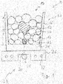
- Fig. 1 shows a system 10 according to the invention of a dental restoration part 12 and a cooling device 19.
- the dental restoration part 12 is received in a plurality of heat sinks 14 and embedded.
- the heat sink 14 are received as bulk material in a vessel 16, up to a filling level 18.
- the filling level 18 is at about 90% of the container height and without Dentalrestaurationsteil well below, for example, at 80% with introduced Dentalrestaurationsteil 12.
- the heat sinks 18 are substantially spherical, but have contact surfaces 20 in many different forms, ie shapes and sizes on. These are designed so that they offer numerous possibilities to lie flat against the dental restoration part 12.
- different ball sizes are provided, wherein the smallest balls have a size of not less than 0.05 mm.
- the largest balls have a diameter in such a way that they fit into small cavities of the restoration.
- Fig. 1 the contact surfaces are deliberately unevenly distributed. This is intended and enables various investment possibilities on the dental restoration part 12.
- the cooling device 19 also has a stirrer 23. This serves to first stir hot dental restoration part 12 with the first cold heat sinks 14.
- the mass of the heat sink 14 exceeds that of the dental restoration part by a multiple, e.g. by 5 to 200 times, in the illustrated embodiment by 20 times.
- the heat sinks according to the invention preferably have a mean thermal conductivity, significantly larger than plastic and much lower than metal. You can e.g. made of ceramic.
- the dental restoration part 12 is completely accommodated in the bed 22 of heat sinks 14.
- the specific weight of the heat sink 14 is at most as large as that of the dental restoration part 12, and preferably 20% smaller. Therefore, the dental restoration part 12 sinks into the bed 22 and is completely surrounded by the heat sinks 14.
- the stirrer 23 according to the invention is designed in the example as a magnetic stirrer.
- the vessel 16 is non-ferromagnetic, that is permeable to magnetic forces.
- a stir bar 24 is centrally located below in the vessel 16. In a conventional manner is rather elongated and rounded in the illustrated embodiment with a circular cross section and ends.
- the stirring fish 24 has a coating of glass, an enamel coating or PTFE, consisting of Fig. 1 is not apparent.
- the stirrer further includes an actuator plate 26 and a magnet 28 which is received in the actuator plate 26 and rotates about an axis 30.
- control plate 26 has a cooling coil 32, which further cools it.
- the heat sink 14 are postcooled.
- reserve heat sinks 14 can also be kept in a storage container, and after cooling of the dental restoration part 12, the vessel 16 with the heat sinks 14 and the dental restoration part 12 is then completely emptied, and a new bed 22 of heat sinks 14 becomes from the reservoir provided in the vessel 16 for receiving the next hot dental restoration part 12.
- the hot dental restoration part 12 is placed on the bed 22 of heat sinks 14.
- the agitator 23 is then immediately put into operation and causes the heat sinks 14 to move driven by the stirring fish 24.
- the somewhat heavier dental restoration part 12 sinks into the bed 22 of the heat sink 16 and is cooled on all sides.
- Fig. 2 shows a modified embodiment of a system 10 according to the invention.
- the cooling device 19 has a trickle opening 40.
- the trickle orifices 40 are attached to in the lowest point of a bulk material container 42 for heat sink 14.
- the trickle opening 40 is adjustable in terms of their opening size and their opening cross-section. This can be realized via a slider 44, as in Fig. 2 is shown schematically.
- the bulk material container 42 together with the trickle opening 40 acts like an hourglass. From the trickle 40 fall heat sink 14 on the dental restoration part. 12. They form there a kind of heap, under which the dental restoration part 12 is buried, so that it is cooled by the contact with the heat sinks 14.
- FIG. 3 Another embodiment of a system 10 according to the invention is Fig. 3 seen.
- a water bath 46 extends just below the dental restoration part 12.
- the dental restoration part 12 is for this purpose on a pedestal 48, which has a height sufficient that the dental restoration part 12 is at the beginning of the cooling process above the water level.
- heat sink 14 for example, by the trickle opening 40 according to Fig. 2 Now, the dental restoration part 12 is cooled, initially substantially from above.
- the heat sink 14 fall through the provided with a grate 50 pedestal in the water 46. This increases the water level, and the dental restoration part 12 is thereby additionally cooled from below.
- a type of laundry drum is provided as a vessel: Cooling by free convection creates a long waiting time between the completion of the heat treatment and the time at which the restoration can be further processed.
- the cooling is provided in the form of a laundry drum.
- a cylinder that rotates has numerous holes to form a sieve.
- the restoration is either free in the balls or in a fixed, but for the balls "permeable" cage.
- the heat sinks or granules must be able to withstand the maximum temperature of the dental restoration part (about 1000 ° C) and absorb heat as quickly and effectively as possible.
Landscapes
- Health & Medical Sciences (AREA)
- Engineering & Computer Science (AREA)
- Oral & Maxillofacial Surgery (AREA)
- General Engineering & Computer Science (AREA)
- Mechanical Engineering (AREA)
- Animal Behavior & Ethology (AREA)
- General Health & Medical Sciences (AREA)
- Public Health (AREA)
- Veterinary Medicine (AREA)
- Epidemiology (AREA)
- Dentistry (AREA)
- Life Sciences & Earth Sciences (AREA)
- Chemical & Material Sciences (AREA)
- Physics & Mathematics (AREA)
- Thermal Sciences (AREA)
- Combustion & Propulsion (AREA)
- Clinical Laboratory Science (AREA)
- Manufacturing & Machinery (AREA)
- Ceramic Engineering (AREA)
- Dental Tools And Instruments Or Auxiliary Dental Instruments (AREA)
Abstract
Description
- Die Erfindung betrifft ein System aus einen Dentalrestaurationsteil sowie einer Kühlvorrichtung, gemäß dem Oberbegriff der Ansprüche 1 und 2, sowie ein zugehöriges Verfahren, gemäß dem Oberbegriff der Ansprüche 17, 18 und 19.
- Typischerweise werden Dentalrestaurationsteile unter Wärmebehandlung hergestellt. Für die Erwärmung der Dentalrestaurationsteile dienen Dentalöfen, die einen Brennraum aufweisen, in dem meist mehrere Dentalrestaurationsteile zur gleichen Zeit gebrannt werden können.
- Die Dentalrestaurationsteile bestehen häufig aus speziellen Dentalkeramiken wie Lithiumdisilikat oder Zirkoniumoxid und bedürfen einer besonderen Brennkurve, damit die erwünschten Eigenschaften bereitgestellt werden können.
- Vor nicht allzu langer Zeit waren besonders für Zirkoniumoxid hierfür Zykluszeiten von mehreren Stunden, beispielsweise acht Stunden, erforderlich.
- In neuerer Zeit sind Versuche unternommen worden, die Zykluszeit deutlich zu reduzieren auf deutlich geringere Zykluszeiten, selbst bei Zirkoniumoxidrestaurationen. Hierzu hat man eine größere Aufheizrate und eine größere Abkühlrate verwendet. Beides ist aufgrund der eingeleiteten Thermospannungen nicht unkritisch.
- Dies gilt insbesondere für die Abkühlrate, da Thermospannungen dazu führen können, dass das keramische Dentalrestaurationsteil einen Sprödbruch erfährt, oder zumindest einen Riss.
- Mikrorisse sind hier besonders kritisch, da sie häufig übersehen werden. In den Mikrorissen können sich im Mund des Patienten Bakterien ansammeln, die zu Infektionen führen können. Im Wesentlichen wirken sich Mikrorisse bei keramischen Restaurationen negativ auf die Langzeitstabilität und die mechanischen Eigenschaften über die Tragedauer aus.
- Ein weiteres Problem ist die Bruchfestigkeit, gerade bei komplex gestalteten Dentalrestaurationen.
- Um die bekannten Probleme zu vermeiden, wird typischerweise eine Abkühlrate ausgewählt, die gewährleistet, dass keine Risse und keine Restspannungen, insbesondere Zug-Druckspannungen, entstehen.
- Dies führt jedoch dazu, dass gegebenenfalls die Abkühlzeit deutlich länger als die Heizzeit wird, was dem erwünschten kurzen Brennzyklus zuwiderläuft.
- Das Abkühlen erfolgt häufig so, dass eine Brennhaube, in der der Brennraum ausgebildet ist, angehoben wird. Dies hat den Vorteil, dass die Stellfläche, auf der die Dentalrestaurationsteile liegen, nicht durch eine vermeidbare Bewegung erschüttert wird.
- Die eintretende Umgebungsluft führt dann dazu, dass das Dentalrestaurationsteil abkühlt.
- Es ist bereits vorgeschlagen worden, eine Zwangskühlung vorzunehmen, beispielsweise durch ein Gebläse. Ein solches hat jedoch den gravierenden Nachteil, dass die Abkühlung auf der Gebläseseite deutlich schneller erfolgt als auf der von dem Gebläse abgewandten Seite, so dass erhebliche Thermospannungen induziert werden, die zu Brüchen des Dentalrestaurationsteiles führen können.
- Eine verbesserte Lösung zur Verhinderung der asymmetrischen Abkühlung lässt sich der
DE 195 429 841 C1 entnehmen. Bei dieser Lösung wird eine Brennhaube nicht lediglich hochgeschwenkt, sondern zunächst vertikal angehoben und dann erst verschwenkt. Hierdurch lässt sich ein gleichmäßiger Luftzutritt von allen Seiten, und damit eine thermospannungsfreie Abkühlung, ermöglichen. Zur Vermeidung von Wärmespannungen wird die Brennhaube zunächst lediglich etwas angehoben, und daran anschließend stärker, so dass kein zu großes Delta-T entsteht. - Diese Lösung erfordert daher nach wie vor einen vergleichsweise langen Abkühlungszeitraum.
- Demgegenüber liegt der Erfindung die Aufgabe zugrunde, ein System aus einem Dentalrestaurationsteil oder mehreren Dentalrestaurationsteilen und einer Kühlvorrichtung sowie ein zugehöriges Verfahren gemäß den Oberbegriffen der Ansprüche 1, 2, 17, 18, 19 zu schaffen, die hinsichtlich der Kühleffizienz verbessert sind, ohne dass thermische Spannungen entstehen würden.
- Diese Aufgabe wird erfindungsgemäß durch die Merkmale der Hauptansprüche gelöst. Vorteilhafte Weiterbildungen ergeben sich aus den Unteransprüchen.
- Erfindungsgemäß besonders günstig ist es, wenn das oder die Dentalrestaurationsteile in dem Bett aus Kühlkörpern in Kontakt mit diesen sind und so eine Abkühlung über eine Festkörper-Wärmeleitung erfolgen kann.
- Das Dentalrestaurationsteil oder die Dentalrestaurationsteile ist oder sind von allen Seiten von Kühlkörpern umgeben. Dies bedeutet, dass eine einseitige Abkühlung wie bei der Verwendung eines Gebläses ausgeschlossen ist. Vielmehr wird das Dentalrestaurationsteil von allen Seiten gleichmäßig gekühlt.
- Erfindungsgemäß wichtig ist auch die Relativbewegung zwischen dem Dentalrestaurationsteil und den Kühlkörpern über eine Bewegungsvorrichtung. Diese erlaubt es, immer neue und insofern kühlere Kühlkörper an das Dentalrestaurationsteil heranzuführen. Die erwärmten Kühlkörper werden abgeführt oder in dem Haufen oder Bett für die Dentalrestaurationsteile vermischt.
- Die Relativbewegung zwischen dem Dentalrestaurationsteil und den Kühlkörpern kann in beliebiger geeigneter Weise durch die Bewegungsvorrichtung realisiert werden. Beispielsweise kann das Dentalrestaurationsteil in einem Strom von Kühlkörpern gehalten werden. In diesem Fall ist es günstig, wenn das Dentalrestaurationsteil durch den Strom auch mit gedreht wird, damit immer neue Seiten des Dentalrestaurationsteiles mit dem Strom der Kühlkörper in Kontakt geraten.
- Erfindungsgemäß ist es günstig, wenn mindestens ein Teil der Abkühlphase durch das erfindungsgemäße Verfahren mit der Relativbewegung zwischen Kühlkörpern und den Dentalrestaurationsteilen realisiert wird.
- Sehr heisse Dentalrestaurationsteile können so zunächst beispielsweise in der Umgebungsluft für eine kurze Zeit abkühlen. Zu diesem Zeitpunkt ist das Delta-T sehr groß, so dass auch eine Konvektionskühlung noch wirksam ist.
- Beispielsweise kann man so Zirkondioxid nach dem Sintern und öffnen des Ofenkopfes von ca. 1200 Grad abkühlen lassen, oder Lithiumdisilikat von ca. 700 Grad. In beiden Fällen ist die Verfestigung der Keramik so weit fortgeschritten, dass eine Bewegung des Dentalrestaurationsteiles unkritisch ist.
- Hier anschließend wird das Dentalrestaurationsteil mit den Kühlkörpern als Schüttgut in Kontakt gebracht, oder das Schüttgut wird dem Dentalrestaurationsteile zugeführt. Die erfindungsgemäß wirksame und gleichmäßig Kontaktkühlung oder Wärmeleitungskühlung wird in Gang gesetzt.
- Unter "Dentalrestaurationsteil" seien hier sämtliche möglichen Arten von Dentalrestaurationsteilen im Singular oder im Plural zu subsumieren: Beispielsweise Zähne, die basierend auf Standardvorgaben hergestellt sind, oder solche, die speziell an den Patienten angepasst sind. Auch Inlays, Onlays, Brücken, Kronen, Teilkronen, Abutments und Abutmentkronen und Zahnbögen, Teilzahnbögen, Teilprothesen, Vollprothesen sowie beliebige andere wärmezubehandelnde Dentalprodukte.
- Ferner seien hierunter Muffeln zu verstehen, in die Dentalrestaurationsteile eingebettet sind.
- Zu den für die Dentalrestaurationsteile verwendeten Materialien gehören Keramiken, Composites und Metalle und Metalllegierungen sowie sämtliche anderen Dentalwerkstoffe, die eine Wärmebehandlung benötigen.
- Für die Bereitstellung der Relativbewegung kann eine beliebige geeignete Bewegungsrichtung eingesetzt werden. Hierzu gehört beispielsweise eine Vorrichtung mit einer Rieselöffnung. Die Rieselöffnung kann sich oberhalb, unterhalb oder seitlich des Dentalrestaurationsteiles befinden und die Kühlkörper als Schüttgut durchlassen, und zwar in einer vorgegebenen Strömungsrate.
- Die Strömungsrate kann zudem einstellbar sein, beispielsweise indem die Größe oder Form der Rieselöffnung verstellt wird.
- Die Rieselöffnung kann sowohl stromauf als auch stromab des Dentalrestaurationsteiles vorgesehen sein.
- Das Dentalrestaurationsteil kann auf einer Art Rost oder Sieb gehalten sein, das so geformt ist, dass die Bewegung der Kühlkörper zu einer Bewegung des Dentalrestaurationsteiles führt.
- Hierzu kann beispielsweise der Strom der Kühlkörper mit seiner Haupt-Strömungsrichtung etwas seitlich der Mitte des Dentalrestaurationsteiles geführt sein, so dass das Dentalrestaurationsteil durch die Reibung der Kühlkörper mit gedreht wird.
- Die Kühlkörper können auch in einer Siebtrommel nach der Art einer Wäschetrommel zusammen mit dem Dentalrestaurationsteil bewegt werden. Deren Sieböffnungen können so klein gewählt werden, dass die Kühlkörper hindurch passen, das Dentalrestaurationsteil hingegen nicht.
- Bevorzugt sind die Kühlkörper abriebfest und staubfrei, so dass keine Verunreinigung an dem Dentalrestaurationsteil verbleiben.
- Bevorzugt weisen die Kühlkörper Kontaktflächen auf, die unterschiedlich geformt sind, so dass auch bei verschiedenen Dentalrestaurationsteilen passende Kontaktflächen vorliegen und eine flächige Anlage möglich ist. Hierdurch wird die Wärmeableitung von der Restauration zum Kühlkörper verbessert.
- Es kann aber auch vorteilhaft sein, wenn die Kühlkörper im Wesentlichen kugelförmig sind.
- Kühlkörper mit besserer Rundheit haben beste Fliesseigenschaften, was der Kühlwirkung gerade durch die intensive Bewegung zugute kommt. Zudem wird durch solche Kühlkörper vermieden, dass Vorsprünge dieser die Dentalrestauration beschädigen können.
- Wenn die Kontakte zu den Dentalrestaurationsteilen aufgrund der balligen Ausgestaltung der Kontaktflächen eher punktförmig sind, erfolgt eine lediglich punktförmig Wärmeableitung. Dann ist es wichtig, dass eine Vielzahl von Kontaktpunkten vorliegen, um dennoch die gewünschte intensive, aber schonende Kühlung sicherzustellen
- Bei geringerer Relativgröße der Kühlkörper zu den Dentalrestaurationsteilen entsteht eine größere Anzahl von Kontaktpunkten, und dementsprechend eine intensivere Kühlung.
- Durch entsprechende Dimensionierung läßt sich insofern die Kühlleistung in weiten Bereichen an die Erfordernisse anpassen.
- Vorsorglich kann dennoch das Dentalrestaurationsteil nach der erfindungsgemäßen Abkühlung beispielsweise durch Druckluft gereinigt werden.
- Besonders günstig ist auch eine Tiefkühlvorrichtung als Teil der Kühlvorrichtung. Diese kann die Kühlkörper bei Bedarf nachkühlen. Hierzu gerät ein sich ändernden Teil der Kühlkörper während Ihrer Relativbewegung bezogen auf das Dentalrestaurationsteil oder die Muffel in die Nachbarschaft der Tiefkühlvorrichtung und wird nachgekühlt.
- Dies ist besonders für die letzte Kühlungsphase nahe der Raumtemperatur günstig, da diese dann signifikant beschleunigt werden kann. Die Tiefkühlvorrichtung kann extern oder bevorzugt unten in dem Relativbewegungsraum der Kühlkörper angeordnet sein.
- Erfindungsgemäß ist es günstig, wenn die Kühlkörper aus einem Material bestehen, das eine gute Wärmeabfuhr ermöglicht. Beispielsweise ist es möglich, gesinterte Keramikkörper mit gezielt ausgebildeten Kontaktflächen als Kühlkörper zu verwenden. Alternativ kann auch eine metallische Realisierung der Kühlkörper angestrebt werden, beispielsweise gerade, wenn eine Muffel gekühlt werden soll, wobei metallische Kühlkörper eine verbesserte Wärmeleitung ermöglichen. Ein Werkstoffverbund oder Verbundwerkstoffe aus Metall und Keramik sind ebenfalls günstig, da dann die Keramikaussenfläche abriebfest ist und eine Kontamination verhindert und Metallkerne die Wärmeabfuhr beschleunigen.
- Es sind auch mit Keramik beschichtete Metallkugeln besonders günstig für den Einsatz als Kühlkörper.
- Es versteht sich, dass die Kühlkörper die maximal bestehende Temperatur des Dentalrestaurationsteiles aushalten können, beispielsweise 1200 Grad Celsius oder 1000 Grad Celsius.
- Durch die Anlage und Kontaktierung erfolgt eine Wärmeübertragung vom Dentalrestaurationsteil auf die Kühlkörper. Hierdurch werden die Kühlkörper etwas erwärmt und das Dentalrestaurationsteil stark abgekühlt. Die Masse der Dentalrestaurationsteile soll lediglich ein Bruchteil der Gesamtmasse der Kühlkörper betragen, beispielsweise 10 bis 100 %. Gleiches gilt für die Wärmekapazität.
- Dennoch steigt die Temperatur der Kühlkörper durch die insofern bestehende Wärmezufuhr leicht an. Um dies zu kompensieren, können kühlere Kühlkörper gegen Ende des Abkühl-Zyklus zugeführt werden, beispielsweise solche, die zuvor in einem Kühlschrank aufbewahrt wurden.
- In vorteilhafter Ausgestaltung ist es vorgesehen, dass die Kühlkörper je eine Mehrzahl von Kontaktflächen für den Kontakt mit dem Dentalrestaurationsteil aufweisen, die insbesondere unterschiedliche Größen und Formen aufweisen.
- In weiterer vorteilhafter Ausgestaltung ist es vorgesehen, dass die Kühlkörper ballige Kontaktflächen, gerade Kontaktflächen und/oder konkave und/oder konvexe Kontaktflächen aufweisen, insbesondere eine Kombination dieser.
- Die Kühlkörper und das Dentalrestaurationsteil sind einem beliebig gestalteten Raum untergebracht, in welchem sie ihre Bewegung relativ zueinander unter wechselnden Kontakten vollziehen. Dieser Raum wird insofern als Relativbewegungsraum bezeichnet und kann z.B. ein Gefäß oder ein Teil eines Gefäßes oder z.B. der Raum oberhalb einer Unterlage sein.
- Eine andere Möglichkeit besteht darin, ein Wasserbett unterhalb eines Rost oder Siebs für die Aufnahme des Dentalrestaurationsteiles vorzusehen. Die Kühlkörper fallen dann zunächst auf das heiße Dentalrestaurationsteil und kühlen es ab. Wenn eine Temperatur etwas oberhalb der Raumtemperatur, beispielsweise 60 Grad Celsius, erreicht ist, wird die Zufuhr der Kühlkörper so fortgesetzt, dass diese, die als Schüttgut vorliegen, neben dem Rost oder Sieb oder durch es hindurch in das Wasserbett rutschen. Der Pegel des Wassers steigt an, so dass das Wasser das Dentalrestaurationsteil erreichen kann und dieses weiter abkühlt.
- Besonders günstig ist es, wenn die Kühlkörper ein spezifisches Gewicht aufweisen, das dem des Dentalrestaurationsteils, ggf. einschließlich seiner Einbettung, mit einer Abweichung von höchstens +/- 30 %, insbesondere höchstens +/- 10%, entspricht.
- Eine schwerkraftunterstützte Bewegung der Kühlkörper relativ zum Dentalrestaurationsteil ist bevorzugt. In vorteilhafter Ausgestaltung ist es vorgesehen, dass die zunächst größere und dann kleinere Kühlkörper mit dem Dentalrestaurationsteil in Anlage gebracht werden. Die Kühlgeschwindigkeit ist direkt von der Anzahl der Kontaktpunkte abhängig, welche wiederum näherungsweise mit 1/Durchmesser2 von der Kühlkörpergröße abhängig ist, so dass hierdurch gegen Ende des Kühlzyklus in Hinblick auf das sinkende Delta T die Kühlgeschwindigkeit wieder erhöht werden kann.
- Wenn dies nicht möglich ist, ist alternativ auch die Möglichkeit des Einsatzes eines Rührers, z.B. eines Magnetrührers, gegeben. Dieser weist typischerweise einen Rührfisch auf, der sowohl die Kühlkörper als auch die Dentalrestaurationsteile bewegt und für die erwünschte wechselnde Kontaktgabe sorgt.
- In einer andere Ausführungsform ist es vorgesehen, dass das Dentalrestaurationsteil bei ausgeschaltetem Rührer auf die Kühlkörper auflegbar ist, ohne dass es einsinkt und bei eingeschalteten Rührer zusammen mit den Kühlkörpern in diese eingesunken bewegt wird.
- Vorteilhaft kann der Rührer ein Magnetrührer sein, dessen Rührfisch mit einem temperaturfesten, glatten und nicht abrasiven Material umhüllt ist, kantenfrei ist und Abrundungen aufweist. Dessen Radius beträgt mindestens 3 mm, insbesondere mind. 5 mm. Bei dieser Ausführungsform kann der Rührer mit einer abriebfesten und wärmefesten Beschichtung versehen sein, beispielsweise emailliert, und zudem kantenfrei sein.
- Bei dieser Ausführungsform kann es vorgesehen sein, dass der Rührer ein elektrisch betriebener Rührer ist, der insbesondere beim Auflegen eines Dentalrestaurationsteils automatisch einschaltbar ist
- Weitere Vorteile, Einzelheiten und Merkmale ergeben sich aus der nachstehenden Beschreibung mehrere Ausführungsbeispiele der Erfindung anhand der Zeichnung.
- Es zeigen:
- Fig. 1
- eine schematische Seitenansicht einer Ausführungsform der Erfindung;
- Fig. 2
- eine weitere Ausführungsform der Erfindung, ebenfalls in schematischer Darstellung; und
- Fig. 3
- eine dritte Ausführungsform der Erfindung, die gegenüber
Fig. 2 modifiziert ist. -
Fig. 1 zeigt eine erfindungsgemäße System 10 aus einem Dentalrestaurationsteil 12 und einer Kühlvorrichtung 19. Das Dentalrestaurationsteil 12 ist in einer Vielzahl von Kühlkörpern 14 aufgenommen und eingebettet. - Die Kühlkörper 14 sind als Schüttgut in einem Gefäß 16 aufgenommen, und zwar bis zu einer Füllhöhe 18. Die Füllhöhe 18 liegt bei eingebrachtem Dentalrestaurationsteil 12 bei etwa 90% der Gefäßhöhe und ohne Dentalrestaurationsteil deutlich darunter, beispielsweise bei 80%.
- Die Kühlkörper 18 sind im Wesentlichen kugelförmig, weisen jedoch Kontaktflächen 20 in zahlreichen unterschiedlichen Ausprägungen, also Formen und Größen, auf. Diese sind so ausgelegt, dass sie zahlreiche Möglichkeiten bieten, flächig an dem Dentalrestaurationsteil 12 anzuliegen.
- Bevorzugt sind unterschiedliche Kugelgrößen vorgesehen, wobei die kleinsten Kugeln eine Größe von nicht weniger als 0.05 mm haben. Bevorzugt weisen die größten Kugeln einen Durchmesser in der Weise auf, dass sie auch in kleine Kavitäten der Restauration passen.
- Durch die Kontaktflächen 20 wird der Wärmeübergang besonders gut unterstützt.
- In
Fig. 1 sind die Kontaktflächen bewusst ungleichmäßig verteilt dargestellt. Dies ist beabsichtigt und ermöglicht verschiedene Anlagemöglichkeiten an dem Dentalrestaurationsteil 12. - Die erfindungsgemäße Kühlvorrichtung 19 weist auch einen Rührer 23 auf. Dieser dient dazu, dass zunächst heiße Dentalrestaurationsteil 12 mit den zunächst kalten Kühlkörpern 14 umzurühren. Die Masse der Kühlkörper 14 übersteigt diejenige des Dentalrestaurationsteiles um ein Mehrfaches, z.B. um das 5- bis 200-fache, im dargestellten Ausführungsbeispiel um das 20-fache.
- Durch die Rührbewegung erfolgt eine wechselnde Anlage von Flächen des Dentalrestaurationsteiles 12 an Kontaktflächen 20 der Kühlkörper 14. Hierdurch kommen immer neue und häufig kalte Kontaktflächen 20 mit dem Dentalrestaurationsteil 12 in Anlage, die dieses überraschend rasch, aber dennoch schonend abkühlen.
- Die Kühlkörper weisen erfindungsgemäß bevorzugt einen mittleren Wärmeleitwert auf, deutlich größer als Kunststoff und deutlich geringer als Metall. Sie können z.B. aus Keramik bestehen.
- Besonders günstig ist es, dass das Dentalrestaurationsteil 12 vollständig in dem Bett 22 aus Kühlkörpern 14 aufgenommen ist. Um dies sicherzustellen, ist das spezifische Gewicht der Kühlkörper 14 höchstens so groß wie dasjenige des Dentalrestaurationsteiles 12, und bevorzugt 20% kleiner. Daher sinkt das Dentalrestaurationsteil 12 in das Bett 22 ein und ist dort vollständig von den Kühlkörpern 14 umgeben.
- Der erfindungsgemäße Rührer 23 ist im Beispielsfall als Magnetrührer ausgebildet. Hierzu ist das Gefäß 16 nicht-ferromagnetisch, also für Magnetkräfte durchlässig. Ein Rührfisch 24 ist unten zentral in dem Gefäß 16 aufgenommen. In an sich bekannter Weise ist eher länglich und im dargestellten Ausführungsbeispiel mit kreisrundem Querschnitt und endseitig verrundet.
- Der Rührfisch 24 weist eine Beschichtung aus Glas, einer Emaillierung oder aus PTFE auf, die aus
Fig. 1 nicht ersichtlich ist. - Zum Rührer gehört ferner eine Stellplatte 26 sowie ein Magnet 28, der in der Stellplatte 26 aufgenommen ist und sich um eine Achse 30 dreht.
- Aufgrund der Magnetkraft dreht sich auch der Rührfisch 24 in an sich bekannter Weise um die Achse 30 mit und setzt dadurch die Kühlkörper 14 und das Dentalrestaurationsteil 12 in Bewegung.
- Durch diese Bewegung gelangen immer neue Stellen des Dentalrestaurationsteils 12 in Kontakt mit unterschiedlichen Kontaktflächen 20 an unterschiedlichen Kühlkörpern.
- In dem dargestellten Ausführungsbeispiel weist die Stellplatte 26 eine Kühlschlange 32 auf, die sie weiter abkühlt. Über den vergleichsweise dicken Boden 36 des Gefäßes 16, der auf der Stellplatte 26 auffliegt, werden die Kühlkörper 14 nachgekühlt.
- Bei entsprechend großem und dementsprechend günstigem Massenverhältnis zwischen Kühlkörpern 14 und Dentalrestaurationsteil 12 ist dies jedoch nicht erforderlich, so dass eine Nachkühlung entbehrlich ist.
- Alternativ zur Nachkühlung können auch Reserve-Kühlkörper 14 in einem Vorratsbehälter bereitgehalten werden, und nach Abkühlung des Dentalrestaurationsteiles 12 wird dann kurzerhand das Gefäß 16 mit den Kühlkörpern 14 und dem Dentalrestaurationsteil 12 vollständig entleert, und aus dem Vorratsbehälter wird ein neues Bett 22 an Kühlkörpern 14 in dem Gefäß 16 für die Aufnahme des nächsten heißen Dentalrestaurationsteiles 12 bereitgestellt.
- Für den Betrieb der erfindungsgemäßen Kühlvorrichtung 19 wird zunächst das heiße Dentalrestaurationsteil 12 auf das Bett 22 aus Kühlkörpern 14 aufgelegt. Der Rührer 23 wird dann umgehend in Betrieb genommen und bewirkt, dass sich die Kühlkörper 14 angetrieben durch den Rührfisch 24 bewegen.
- Hierdurch sinkt das etwas schwerere Dentalrestaurationsteil 12 in das Bett 22 der Kühlkörper 16 ein und wird allseitig gekühlt.
-
Fig. 2 zeigt eine modifizierte Ausführungsform eines erfindungsgemäßen Systems 10. In dieser Ausführungsform weist die Kühlvorrichtung 19 eine Rieselöffnung 40 auf. Die Rieselöffnungen 40 ist an in der untersten Stelle eines Schüttgutbehälter 42 für Kühlkörper 14 angebracht. - Bevorzugt ist die Rieselöffnung 40 hinsichtlich ihrer Öffnungsgröße und ihres Öffnungsquerschnitts verstellbar. Dies lässt sich über einen Schieber 44 realisieren, wie er in
Fig. 2 schematisch dargestellt ist. - Der Schüttgutbehälter 42 zusammen mit der Rieselöffnung 40 wirkt wie eine Sanduhr. Aus der Rieselöffnung 40 fallen Kühlkörper 14 auf das Dentalrestaurationsteil. 12. Sie bilden dort eine Art Haufen, unter dem das Dentalrestaurationsteil 12 begraben ist, so dass es durch den Kontakt mit den Kühlkörpern 14 gekühlt wird.
- In einer weiter modifizierten Ausführungsform ist es vorgesehen, unterhalb des Dentalrestaurationsteiles 12 eine kleine Rüttelvorrichtungen anzubringen. Durch diese werden immer neue Kühlkörper 14 mit dem Dentalrestaurationsteil in Kontakt gebracht, so dass die Kühlung intensiviert wird.
- Eine weitere Ausführungsform eines erfindungsgemäßen Systems 10 ist aus
Fig. 3 ersichtlich. Dort erstreckt sich ein Wasserbad 46 knapp unterhalb des Dentalrestaurationsteiles 12. Das Dentalrestaurationsteil 12 liegt hierzu auf einem Podest 48, dass eine Höhe hat, die ausreicht, dass das Dentalrestaurationsteil 12 bei Beginn des Kühlvorgangs sich oberhalb des Wasserspiegels befindet. Durch aufgebrachte Kühlkörper 14, beispielsweise durch die Rieselöffnung 40 gemäßFig. 2 , wird nun das Dentalrestaurationsteil 12 gekühlt, und zwar zunächst im Wesentlichen von oben. - Die Kühlkörper 14 fallen durch das mit einem Rost 50 versehene Podest in das Wasser 46. Hierdurch steigt der Wasserspiegel, und das Dentalrestaurationsteil 12 wird hierdurch zusätzlich auch von unten gekühlt.
- Günstig ist hier eine erst schonende Abkühlung durch die Kugeln und dann, wenn das Thema Thermoschock nicht mehr heikel ist, z.B. bei ca. 60°C, wird noch schnell mit Wasser auf Endtemperatur gekühlt. Hierdurch wird das Delta T wieder vergrößert, damit die Endabkühlung nicht zu langsam vonstattengeht.
- Anstelle des hier erwähnten Wassers kann auch ein beliebiges anderes liquides Kühlmedium verwendet werden, das sich mit dem jeweils verwendeten Material des Dentalrestaurationsteiles 12 verträgt.
- Insbesondere ist es günstig, die Wärmeleitfähigkeit und Wärmekapazität, aber auch die Masse des Kühlmedium an die der Kühlkörper 14 anzupassen, um so für eine gleichmäßige Abkühlung zu sorgen.
- In einer weiteren Ausführungsform ist eine Art Wäschetrommel als Gefäß vorgesehen:
Beim Kühlen durch freie Konvektion entsteht eine lange Wartezeit zwischen dem Abschluss der Wärmebehandlung und dem Zeitpunkt, zu dem die Restauration weiterverarbeitet werden kann. - In einer erfindungsgemäßen Ausführungsform ist die Abkühlung in Form einer Wäschetrommel vorgesehen. Ein Zylinder, der sich dreht, weist zahlreiche Löcher zur Bildung eines Siebs auf. Die Restauration liegt entweder frei in den Kugeln oder in einem fixen, aber für die Kugeln "durchlässigen" Käfig.
- Die Kühlkörper oder das Granulat muss die maximale Temperatur des Dentalrestaurationsteils aushalten (ca. 1000°C), und möglichst rasch und gut Wärme aufnehmen.
- Besonders günstig ist es - unabhängig von der Ausführungsform - , wenn sich die Restauration in einem definierten Bereich /an einem definierten Ort befindet, damit man sie nicht nach Ende des Kühlvorgangs in den Kühlkörpern suchen gehen muss
Claims (20)
- System aus einem Dentalrestaurationsteil oder mehreren Dentalrestaurationsteilen, und/oder mit einem gegebenenfalls in eine Muffel eingebetteten Dentalrestaurationsteil, und einer Kühlvorrichtung, dadurch gekennzeichnet, dass die Kühlvorrichtung Kühlkörper (14) als Schüttgut und eine Bewegungsvorrichtung aufweist, mit welcher Kühlkörper (14) und das oder die Dentalrestaurationsteile (12) relativ zueinander bewegbar sind.
- System aus einem Dentalrestaurationsteil oder mehreren Dentalrestaurationsteilen und/oder mit einem gegebenenfalls in eine Muffel eingebetteten Dentalrestaurationsteil und einer Kühlvorrichtung dadurch gekennzeichnet, dass die Kühlvorrichtung Kühlkörper (14) als Schüttgut aufweist, und dass die Kühlvorrichtung(19) eine Rieselöffnung (40) für die Kühlkörper (14) aufweist, insbesondere oberhalb und/oder unterhalb des Dentalrestaurationsteiles (12).
- System nach Anspruch 1 oder 2, dadurch gekennzeichnet, dass die Bewegungsvorrichtung ein Bewegungselement aufweist der dafür bestimmt ist, die Kühlkörper (14) zusammen mit dem Dentalrestaurationsteil zu bewegen, insbesondere in einem Relativbewegungsraum von Kühlkörper (14) und Dentalrestaurationsteil (12).
- System nach Anspruch 1, dadurch gekennzeichnet, dass die Kühlkörper (14) als Granulat, als Hohlkörper, als prismatische Körper, als Quader mit abgerundeten Ecken und Kanten und/oder als runde Körper, insbesondere im wesentlichen in Kugelform, je mit Kontaktflächen, ausgebildet sind.
- System nach einem der vorhergehenden Ansprüche, dadurch gekennzeichnet, dass die Anzahl der Kontaktpunkte und/oder Kontaktflächen zwischen Dentalrestaurationsteil und Kühlkörpern zwischen 3 Kontakten/cm2 und 100.000 Kontakten/cm2 beträgt, insbesondere zwischen 12 Kontakten/cm2 und 12.000 Kontakten/cm2.
- System nach einem der vorhergehenden Ansprüche, dadurch gekennzeichnet, dass die Kühlkörper (14) aus keramischem Material bestehen, insbesondere aus Aluminiumoxid oder Zirkoniumdioxid, oder aus Glas oder aus Metall, letzteres insbesondere für die Kühlung einer Muffel, oder aus Verbundwerkstoffen oder Werkstoffverbunden der o.g. Materialklassen sowie mit Glas oder Keramik beschichtete Metallkühlkörper.
- System nach einem der vorhergehenden Ansprüche, dadurch gekennzeichnet, dass die Kühlkörper (14) für Dentalrestaurationsteile (12) eine Größe zwischen 50 µm und 10 mm aufweisen.
- System nach einem der vorhergehenden Ansprüche, dadurch gekennzeichnet, dass ein geschlossenes oder offenes Gefäß (16) die Kühlkörper (14) und das Dentalrestaurationsteil (12) aufnimmt, wobei insbesondere das Volumen der Kühlkörper (14) mindestens das 3-fache des Volumens des Dentalrestaurationsteiles (12) ist.
- System nach Anspruch 8 und 9, dadurch gekennzeichnet, dass das Gefäß (16) für die Aufnahme der Kühlkörper und des Dentalrestaurationsteils, ggf. einschließlich der Muffel, eine Kühlkörper-Auflagefläche aufweist, die ihrerseits insbesondere aktive Kühlelemente aufweist, über welche die Kühlkörper ggf. nachkühlbar sind
- System nach einem der vorhergehenden Ansprüche, dadurch gekennzeichnet, dass ein Gefäß (16) für die Aufnahme der Kühlkörper (14) und des Dentalrestaurationsteils (12) eine Aufnahmevolumen aufweist, das ein Vielfaches des Volumens des Dentalrestaurationsteils beträgt.
- System nach einem der vorhergehenden Ansprüche, dadurch gekennzeichnet, dass nicht benötigte Kühlkörper in einem auf Raumtemperatur befindlichen Gefäß aufbewahrt sind und mit den benötigten Kühlkörpern austauschbar sind.
- System nach einem der vorhergehenden Ansprüche, dadurch gekennzeichnet, dass eine Tiefkühlvorrichtung als Teil der Kühlvorrichtung einem Teil, insbesondere einem sich ändernden Teil, der Kühlkörper (14) während Ihrer Relativbewegung bezogen auf das Dentalrestaurationsteil oder die Muffel, insbesondere zur Nachkühlung dieser, benachbart ist oder in deren Nachbarschaft gerät, unter Kühlung der Kühlkörper (14) durch die Tiefkühlvorrichtung, und dass die Tiefkühlvorrichtung insbesondere unten in dem Relativbewegungsraum der Kühlkörper (14) angeordnet ist.
- System nach einem der vorhergehenden Ansprüche, dadurch gekennzeichnet, dass mindestens teilweise die Kühlvorrichtung, insbesondere mindestens ein Teil der Kühlkörper (14) in einer Tiefkühlvorrichtung aufbewahrt ist, auf einer Temperatur deutlich unterhalb der Raumtemperatur, insbesondere unter 0 Grad, und für die Verwendung gegen Ende der Kühlphase bestimmt ist.
- System nach einem der vorhergehenden Ansprüche, dadurch gekennzeichnet, dass ein Gefäß (16) für die Aufnahme des Dentalrestaurationsteiles oder der Dentalrestaurationsteile und der Kühlkörper eine Flüssigkeit (z.B. Wasser 46) aufweist.
- System nach Anspruch 14, dadurch gekennzeichnet, dass die Flüssigkeit sich vor der Aufbringung oder Einbringung der Kühlkörper (14) unterhalb des Dentalrestaurationsteiles befindet und deren Pegel durch Einbringen der Kühlkörper (14) ansteigt und insbesondere das Dentalrestaurationsteil (12) erreicht.
- System nach einem der Ansprüche 2 bis 15, dadurch gekennzeichnet, dass die Rieselöffnung (40) in ihrer Größe und/oder Abmessung einstellbar ist.
- Verfahren zum Kühlen eines gegebenenfalls in eine Muffel eingebetteten Dentalrestaurationsteils (12), unter Verwendung einer Kühlvorrichtung (19), dadurch gekennzeichnet, dass das Dentalrestaurationsteil (12) in einem Bett von losen Kühlkörpern (14) der Kühlvorrichtung (19) aufgenommen ist, welche Kühlkörper (14) als Schüttgut relativ zu dem Dentalrestaurationsteil (12) bewegt werden, wobei wechselnde Kontaktflächen (20) der Kühlkörper (14) mit dem Dentalrestaurationsteil (12) in Anlage geraten und dieses dort kühlen.
- Verfahren zum Kühlen eines gegebenenfalls in eine Muffel eingebetteten Dentalrestaurationsteils (12), unter Verwendung einer Kühlvorrichtung (19), dadurch gekennzeichnet, dass Kühlkörper (14) aus einem Schüttgutbehälter (42) oberhalb des Dentalrestaurationsteil (12), insbesondere durch eine Rieselöffnung, auf das Dentalrestaurationsteil fallen, wobei, ggf. wechselnde, Kontaktflächen (20) der Kühlkörper (14) mit dem Dentalrestaurationsteil (12) in Anlage geraten und dieses dort kühlen.
- Verfahren zum Kühlen eines gegebenenfalls in eine Muffel eingebetteten Dentalrestaurationsteils (12), unter Verwendung einer Kühlvorrichtung (19), dadurch gekennzeichnet, dass eine Mehrzahl von Kühlkörpern (14), mit einer Größe von mehr als 1 mm, je mit, ggf. wechselnden, Kontaktflächen (20) mit dem oder den Dentalrestaurationsteilen in Anlage oder in Kälteleitverbindung geraten und dieses dort kühlen.
- Verfahren zum Kühlen eines gegebenenfalls in eine Muffel eingebetteten Dentalrestaurationsteils, gemäß einem der Ansprüche 17, 18 und 19, dadurch gekennzeichnet, dass die zunächst größere und dann kleinere Kühlkörper mit dem Dentalrestaurationsteil (12) in Anlage gebracht werden.
Priority Applications (4)
| Application Number | Priority Date | Filing Date | Title |
|---|---|---|---|
| EP18170105.3A EP3563796B1 (de) | 2018-04-30 | 2018-04-30 | System aus dentalrestaurationsteil(en) und kühlvorrichtung sowie verfahren |
| CN201910336393.6A CN110403722A (zh) | 2018-04-30 | 2019-04-25 | 包括牙科修复件和冷却装置的系统以及方法 |
| JP2019086872A JP2019193793A (ja) | 2018-04-30 | 2019-04-26 | 歯科補綴材(群)と冷却装置からなるシステムならびに方法 |
| US16/396,907 US20190331421A1 (en) | 2018-04-30 | 2019-04-29 | System, device and process for cooling dental restoration parts |
Applications Claiming Priority (1)
| Application Number | Priority Date | Filing Date | Title |
|---|---|---|---|
| EP18170105.3A EP3563796B1 (de) | 2018-04-30 | 2018-04-30 | System aus dentalrestaurationsteil(en) und kühlvorrichtung sowie verfahren |
Publications (2)
| Publication Number | Publication Date |
|---|---|
| EP3563796A1 true EP3563796A1 (de) | 2019-11-06 |
| EP3563796B1 EP3563796B1 (de) | 2022-10-05 |
Family
ID=62091759
Family Applications (1)
| Application Number | Title | Priority Date | Filing Date |
|---|---|---|---|
| EP18170105.3A Active EP3563796B1 (de) | 2018-04-30 | 2018-04-30 | System aus dentalrestaurationsteil(en) und kühlvorrichtung sowie verfahren |
Country Status (4)
| Country | Link |
|---|---|
| US (1) | US20190331421A1 (de) |
| EP (1) | EP3563796B1 (de) |
| JP (1) | JP2019193793A (de) |
| CN (1) | CN110403722A (de) |
Citations (2)
| Publication number | Priority date | Publication date | Assignee | Title |
|---|---|---|---|---|
| US4475370A (en) * | 1983-05-16 | 1984-10-09 | Marvin M. Stark Research Foundation | Device for treating dental castings |
| US20130241095A1 (en) * | 2010-12-09 | 2013-09-19 | 3Mm Innovative Properties Company | System comprising a rapid prototyping device and a material cartridge, a cartridge, and a method of using the system |
Family Cites Families (4)
| Publication number | Priority date | Publication date | Assignee | Title |
|---|---|---|---|---|
| US5064479A (en) * | 1990-05-31 | 1991-11-12 | Union Carbide Industrial Gases Technology Corporation | Thermal treatment in a fluidized bed |
| JPH10141825A (ja) * | 1996-11-11 | 1998-05-29 | Sekisui Chem Co Ltd | 冷却器 |
| US5901775A (en) * | 1996-12-20 | 1999-05-11 | General Kinematics Corporation | Two-stage heat treating decoring and sand reclamation system |
| WO2017201381A1 (en) * | 2016-05-20 | 2017-11-23 | Soundararajan Gopi | Reversible cement |
-
2018
- 2018-04-30 EP EP18170105.3A patent/EP3563796B1/de active Active
-
2019
- 2019-04-25 CN CN201910336393.6A patent/CN110403722A/zh active Pending
- 2019-04-26 JP JP2019086872A patent/JP2019193793A/ja active Pending
- 2019-04-29 US US16/396,907 patent/US20190331421A1/en not_active Abandoned
Patent Citations (2)
| Publication number | Priority date | Publication date | Assignee | Title |
|---|---|---|---|---|
| US4475370A (en) * | 1983-05-16 | 1984-10-09 | Marvin M. Stark Research Foundation | Device for treating dental castings |
| US20130241095A1 (en) * | 2010-12-09 | 2013-09-19 | 3Mm Innovative Properties Company | System comprising a rapid prototyping device and a material cartridge, a cartridge, and a method of using the system |
Also Published As
| Publication number | Publication date |
|---|---|
| US20190331421A1 (en) | 2019-10-31 |
| EP3563796B1 (de) | 2022-10-05 |
| JP2019193793A (ja) | 2019-11-07 |
| CN110403722A (zh) | 2019-11-05 |
Similar Documents
| Publication | Publication Date | Title |
|---|---|---|
| EP2098188B1 (de) | Verfahren zum Sintern eines Dentalmaterials | |
| EP3256804B1 (de) | Sinterofen für bauteile aus sinterwerkstoff, insbesondere dentalbauteile | |
| DE69619873T2 (de) | Verwendung von neuen glaszusammensetzungen zur herstellung von glasstützen für die zahnheilkunde und verfahren zu deren produktion | |
| EP2452651A1 (de) | Dentalofen mit Suszeptor-Behälter | |
| DE2604667C3 (de) | Drehherdofen | |
| DE102012109248A1 (de) | Herstellung von Analyseproben | |
| EP1020245A2 (de) | Verfahren und Vorrichtung zur Herstellung einer Gasturbinenschaufel mittels gerichtetem Erstarren einer Schmelze | |
| EP3132217A1 (de) | Sinterofen für bauteile aus sinterwerkstoff, insbesondere dentalbauteile | |
| DE60220060T2 (de) | Wirbelbildung inhibitor mit opferkörper | |
| DE102004013668B4 (de) | Pressofen sowie Zwischenkörper für einen Pressofen und Verfahren für den Betrieb eines Pressofens | |
| EP2744613B1 (de) | Sintervorrichtung | |
| EP3563796B1 (de) | System aus dentalrestaurationsteil(en) und kühlvorrichtung sowie verfahren | |
| DE69407992T2 (de) | Kompakte pfanne zur behandlung von metallschmelze | |
| DE102012100631A1 (de) | Sintervorrichtung | |
| EP3725262A1 (de) | Dentales ausbettverfahren sowie muffel | |
| DE10241857B4 (de) | Verfahren und Vorrichtung zur Anfertigung einer Form, insbesondere einer Muffel, für die Herstellung von Zahnersatz-Objekten | |
| DE3836939C1 (de) | ||
| DE10016096C2 (de) | Ofen zum Glühen von zu Coils gehaspelten Stahlbändern und Verfahren zum Glühen derselben | |
| DE2216035B2 (de) | Verfahren zur Herstellung von Schmelztabletten für die Röntgenfluoreszenzanalyse | |
| DE3248104C2 (de) | Tiegel zum Schmelzen und Gießen von Dentallegierungen | |
| DE202012103732U1 (de) | Anordnung zur Herstellung von Analyseproben | |
| DE102007004243B4 (de) | Verfahren zum Herstellen eines Verbundkörpers und Verbundkörper | |
| DE1558325A1 (de) | Heizvorrichtung fuer eine Giessform | |
| EP2450004B1 (de) | Pressmuffel | |
| WO2020016062A1 (de) | Schwebeschmelzverfahren mit einem ringförmigen element |
Legal Events
| Date | Code | Title | Description |
|---|---|---|---|
| PUAI | Public reference made under article 153(3) epc to a published international application that has entered the european phase |
Free format text: ORIGINAL CODE: 0009012 |
|
| STAA | Information on the status of an ep patent application or granted ep patent |
Free format text: STATUS: THE APPLICATION HAS BEEN PUBLISHED |
|
| AK | Designated contracting states |
Kind code of ref document: A1 Designated state(s): AL AT BE BG CH CY CZ DE DK EE ES FI FR GB GR HR HU IE IS IT LI LT LU LV MC MK MT NL NO PL PT RO RS SE SI SK SM TR |
|
| AX | Request for extension of the european patent |
Extension state: BA ME |
|
| STAA | Information on the status of an ep patent application or granted ep patent |
Free format text: STATUS: REQUEST FOR EXAMINATION WAS MADE |
|
| 17P | Request for examination filed |
Effective date: 20200505 |
|
| RBV | Designated contracting states (corrected) |
Designated state(s): AL AT BE BG CH CY CZ DE DK EE ES FI FR GB GR HR HU IE IS IT LI LT LU LV MC MK MT NL NO PL PT RO RS SE SI SK SM TR |
|
| STAA | Information on the status of an ep patent application or granted ep patent |
Free format text: STATUS: EXAMINATION IS IN PROGRESS |
|
| 17Q | First examination report despatched |
Effective date: 20200821 |
|
| GRAP | Despatch of communication of intention to grant a patent |
Free format text: ORIGINAL CODE: EPIDOSNIGR1 |
|
| STAA | Information on the status of an ep patent application or granted ep patent |
Free format text: STATUS: GRANT OF PATENT IS INTENDED |
|
| INTG | Intention to grant announced |
Effective date: 20220506 |
|
| GRAS | Grant fee paid |
Free format text: ORIGINAL CODE: EPIDOSNIGR3 |
|
| GRAA | (expected) grant |
Free format text: ORIGINAL CODE: 0009210 |
|
| STAA | Information on the status of an ep patent application or granted ep patent |
Free format text: STATUS: THE PATENT HAS BEEN GRANTED |
|
| AK | Designated contracting states |
Kind code of ref document: B1 Designated state(s): AL AT BE BG CH CY CZ DE DK EE ES FI FR GB GR HR HU IE IS IT LI LT LU LV MC MK MT NL NO PL PT RO RS SE SI SK SM TR |
|
| REG | Reference to a national code |
Ref country code: GB Ref legal event code: FG4D Free format text: NOT ENGLISH |
|
| REG | Reference to a national code |
Ref country code: CH Ref legal event code: EP |
|
| REG | Reference to a national code |
Ref country code: AT Ref legal event code: REF Ref document number: 1522277 Country of ref document: AT Kind code of ref document: T Effective date: 20221015 |
|
| REG | Reference to a national code |
Ref country code: DE Ref legal event code: R096 Ref document number: 502018010751 Country of ref document: DE |
|
| REG | Reference to a national code |
Ref country code: IE Ref legal event code: FG4D Free format text: LANGUAGE OF EP DOCUMENT: GERMAN |
|
| REG | Reference to a national code |
Ref country code: LT Ref legal event code: MG9D |
|
| REG | Reference to a national code |
Ref country code: NL Ref legal event code: MP Effective date: 20221005 |
|
| PG25 | Lapsed in a contracting state [announced via postgrant information from national office to epo] |
Ref country code: NL Free format text: LAPSE BECAUSE OF FAILURE TO SUBMIT A TRANSLATION OF THE DESCRIPTION OR TO PAY THE FEE WITHIN THE PRESCRIBED TIME-LIMIT Effective date: 20221005 |
|
| PG25 | Lapsed in a contracting state [announced via postgrant information from national office to epo] |
Ref country code: SE Free format text: LAPSE BECAUSE OF FAILURE TO SUBMIT A TRANSLATION OF THE DESCRIPTION OR TO PAY THE FEE WITHIN THE PRESCRIBED TIME-LIMIT Effective date: 20221005 Ref country code: PT Free format text: LAPSE BECAUSE OF FAILURE TO SUBMIT A TRANSLATION OF THE DESCRIPTION OR TO PAY THE FEE WITHIN THE PRESCRIBED TIME-LIMIT Effective date: 20230206 Ref country code: NO Free format text: LAPSE BECAUSE OF FAILURE TO SUBMIT A TRANSLATION OF THE DESCRIPTION OR TO PAY THE FEE WITHIN THE PRESCRIBED TIME-LIMIT Effective date: 20230105 Ref country code: LT Free format text: LAPSE BECAUSE OF FAILURE TO SUBMIT A TRANSLATION OF THE DESCRIPTION OR TO PAY THE FEE WITHIN THE PRESCRIBED TIME-LIMIT Effective date: 20221005 Ref country code: FI Free format text: LAPSE BECAUSE OF FAILURE TO SUBMIT A TRANSLATION OF THE DESCRIPTION OR TO PAY THE FEE WITHIN THE PRESCRIBED TIME-LIMIT Effective date: 20221005 Ref country code: ES Free format text: LAPSE BECAUSE OF FAILURE TO SUBMIT A TRANSLATION OF THE DESCRIPTION OR TO PAY THE FEE WITHIN THE PRESCRIBED TIME-LIMIT Effective date: 20221005 |
|
| PG25 | Lapsed in a contracting state [announced via postgrant information from national office to epo] |
Ref country code: RS Free format text: LAPSE BECAUSE OF FAILURE TO SUBMIT A TRANSLATION OF THE DESCRIPTION OR TO PAY THE FEE WITHIN THE PRESCRIBED TIME-LIMIT Effective date: 20221005 Ref country code: PL Free format text: LAPSE BECAUSE OF FAILURE TO SUBMIT A TRANSLATION OF THE DESCRIPTION OR TO PAY THE FEE WITHIN THE PRESCRIBED TIME-LIMIT Effective date: 20221005 Ref country code: LV Free format text: LAPSE BECAUSE OF FAILURE TO SUBMIT A TRANSLATION OF THE DESCRIPTION OR TO PAY THE FEE WITHIN THE PRESCRIBED TIME-LIMIT Effective date: 20221005 Ref country code: IS Free format text: LAPSE BECAUSE OF FAILURE TO SUBMIT A TRANSLATION OF THE DESCRIPTION OR TO PAY THE FEE WITHIN THE PRESCRIBED TIME-LIMIT Effective date: 20230205 Ref country code: HR Free format text: LAPSE BECAUSE OF FAILURE TO SUBMIT A TRANSLATION OF THE DESCRIPTION OR TO PAY THE FEE WITHIN THE PRESCRIBED TIME-LIMIT Effective date: 20221005 Ref country code: GR Free format text: LAPSE BECAUSE OF FAILURE TO SUBMIT A TRANSLATION OF THE DESCRIPTION OR TO PAY THE FEE WITHIN THE PRESCRIBED TIME-LIMIT Effective date: 20230106 |
|
| REG | Reference to a national code |
Ref country code: DE Ref legal event code: R097 Ref document number: 502018010751 Country of ref document: DE |
|
| P01 | Opt-out of the competence of the unified patent court (upc) registered |
Effective date: 20230607 |
|
| PG25 | Lapsed in a contracting state [announced via postgrant information from national office to epo] |
Ref country code: SM Free format text: LAPSE BECAUSE OF FAILURE TO SUBMIT A TRANSLATION OF THE DESCRIPTION OR TO PAY THE FEE WITHIN THE PRESCRIBED TIME-LIMIT Effective date: 20221005 Ref country code: RO Free format text: LAPSE BECAUSE OF FAILURE TO SUBMIT A TRANSLATION OF THE DESCRIPTION OR TO PAY THE FEE WITHIN THE PRESCRIBED TIME-LIMIT Effective date: 20221005 Ref country code: EE Free format text: LAPSE BECAUSE OF FAILURE TO SUBMIT A TRANSLATION OF THE DESCRIPTION OR TO PAY THE FEE WITHIN THE PRESCRIBED TIME-LIMIT Effective date: 20221005 Ref country code: DK Free format text: LAPSE BECAUSE OF FAILURE TO SUBMIT A TRANSLATION OF THE DESCRIPTION OR TO PAY THE FEE WITHIN THE PRESCRIBED TIME-LIMIT Effective date: 20221005 Ref country code: CZ Free format text: LAPSE BECAUSE OF FAILURE TO SUBMIT A TRANSLATION OF THE DESCRIPTION OR TO PAY THE FEE WITHIN THE PRESCRIBED TIME-LIMIT Effective date: 20221005 |
|
| PLBE | No opposition filed within time limit |
Free format text: ORIGINAL CODE: 0009261 |
|
| STAA | Information on the status of an ep patent application or granted ep patent |
Free format text: STATUS: NO OPPOSITION FILED WITHIN TIME LIMIT |
|
| PG25 | Lapsed in a contracting state [announced via postgrant information from national office to epo] |
Ref country code: SK Free format text: LAPSE BECAUSE OF FAILURE TO SUBMIT A TRANSLATION OF THE DESCRIPTION OR TO PAY THE FEE WITHIN THE PRESCRIBED TIME-LIMIT Effective date: 20221005 Ref country code: AL Free format text: LAPSE BECAUSE OF FAILURE TO SUBMIT A TRANSLATION OF THE DESCRIPTION OR TO PAY THE FEE WITHIN THE PRESCRIBED TIME-LIMIT Effective date: 20221005 |
|
| 26N | No opposition filed |
Effective date: 20230706 |
|
| PG25 | Lapsed in a contracting state [announced via postgrant information from national office to epo] |
Ref country code: SI Free format text: LAPSE BECAUSE OF FAILURE TO SUBMIT A TRANSLATION OF THE DESCRIPTION OR TO PAY THE FEE WITHIN THE PRESCRIBED TIME-LIMIT Effective date: 20221005 |
|
| GBPC | Gb: european patent ceased through non-payment of renewal fee |
Effective date: 20230430 |
|
| PG25 | Lapsed in a contracting state [announced via postgrant information from national office to epo] |
Ref country code: LU Free format text: LAPSE BECAUSE OF NON-PAYMENT OF DUE FEES Effective date: 20230430 |
|
| REG | Reference to a national code |
Ref country code: BE Ref legal event code: MM Effective date: 20230430 |
|
| PG25 | Lapsed in a contracting state [announced via postgrant information from national office to epo] |
Ref country code: MC Free format text: LAPSE BECAUSE OF FAILURE TO SUBMIT A TRANSLATION OF THE DESCRIPTION OR TO PAY THE FEE WITHIN THE PRESCRIBED TIME-LIMIT Effective date: 20221005 |
|
| PG25 | Lapsed in a contracting state [announced via postgrant information from national office to epo] |
Ref country code: GB Free format text: LAPSE BECAUSE OF NON-PAYMENT OF DUE FEES Effective date: 20230430 |
|
| PG25 | Lapsed in a contracting state [announced via postgrant information from national office to epo] |
Ref country code: MC Free format text: LAPSE BECAUSE OF FAILURE TO SUBMIT A TRANSLATION OF THE DESCRIPTION OR TO PAY THE FEE WITHIN THE PRESCRIBED TIME-LIMIT Effective date: 20221005 Ref country code: GB Free format text: LAPSE BECAUSE OF NON-PAYMENT OF DUE FEES Effective date: 20230430 Ref country code: FR Free format text: LAPSE BECAUSE OF NON-PAYMENT OF DUE FEES Effective date: 20230430 |
|
| REG | Reference to a national code |
Ref country code: IE Ref legal event code: MM4A |
|
| PG25 | Lapsed in a contracting state [announced via postgrant information from national office to epo] |
Ref country code: BE Free format text: LAPSE BECAUSE OF NON-PAYMENT OF DUE FEES Effective date: 20230430 |
|
| PG25 | Lapsed in a contracting state [announced via postgrant information from national office to epo] |
Ref country code: IE Free format text: LAPSE BECAUSE OF NON-PAYMENT OF DUE FEES Effective date: 20230430 |
|
| PG25 | Lapsed in a contracting state [announced via postgrant information from national office to epo] |
Ref country code: IE Free format text: LAPSE BECAUSE OF NON-PAYMENT OF DUE FEES Effective date: 20230430 |
|
| PGFP | Annual fee paid to national office [announced via postgrant information from national office to epo] |
Ref country code: AT Payment date: 20240308 Year of fee payment: 7 |
|
| PG25 | Lapsed in a contracting state [announced via postgrant information from national office to epo] |
Ref country code: BG Free format text: LAPSE BECAUSE OF FAILURE TO SUBMIT A TRANSLATION OF THE DESCRIPTION OR TO PAY THE FEE WITHIN THE PRESCRIBED TIME-LIMIT Effective date: 20221005 |
|
| PG25 | Lapsed in a contracting state [announced via postgrant information from national office to epo] |
Ref country code: BG Free format text: LAPSE BECAUSE OF FAILURE TO SUBMIT A TRANSLATION OF THE DESCRIPTION OR TO PAY THE FEE WITHIN THE PRESCRIBED TIME-LIMIT Effective date: 20221005 |
|
| PGFP | Annual fee paid to national office [announced via postgrant information from national office to epo] |
Ref country code: IT Payment date: 20250306 Year of fee payment: 8 |
|
| PGFP | Annual fee paid to national office [announced via postgrant information from national office to epo] |
Ref country code: DE Payment date: 20250418 Year of fee payment: 8 |
|
| PGFP | Annual fee paid to national office [announced via postgrant information from national office to epo] |
Ref country code: CH Payment date: 20250522 Year of fee payment: 8 |
|
| PG25 | Lapsed in a contracting state [announced via postgrant information from national office to epo] |
Ref country code: CY Free format text: LAPSE BECAUSE OF FAILURE TO SUBMIT A TRANSLATION OF THE DESCRIPTION OR TO PAY THE FEE WITHIN THE PRESCRIBED TIME-LIMIT; INVALID AB INITIO Effective date: 20180430 |
|
| PG25 | Lapsed in a contracting state [announced via postgrant information from national office to epo] |
Ref country code: HU Free format text: LAPSE BECAUSE OF FAILURE TO SUBMIT A TRANSLATION OF THE DESCRIPTION OR TO PAY THE FEE WITHIN THE PRESCRIBED TIME-LIMIT; INVALID AB INITIO Effective date: 20180430 |
|
| PG25 | Lapsed in a contracting state [announced via postgrant information from national office to epo] |
Ref country code: TR Free format text: LAPSE BECAUSE OF FAILURE TO SUBMIT A TRANSLATION OF THE DESCRIPTION OR TO PAY THE FEE WITHIN THE PRESCRIBED TIME-LIMIT Effective date: 20221005 |
|
| REG | Reference to a national code |
Ref country code: AT Ref legal event code: MM01 Ref document number: 1522277 Country of ref document: AT Kind code of ref document: T Effective date: 20250430 |
|
| PG25 | Lapsed in a contracting state [announced via postgrant information from national office to epo] |
Ref country code: AT Free format text: LAPSE BECAUSE OF NON-PAYMENT OF DUE FEES Effective date: 20250430 |