EP3563776A2 - Agrafes pour générer et appliquer une compression à l'intérieur d'un corps - Google Patents
Agrafes pour générer et appliquer une compression à l'intérieur d'un corps Download PDFInfo
- Publication number
- EP3563776A2 EP3563776A2 EP19177616.0A EP19177616A EP3563776A2 EP 3563776 A2 EP3563776 A2 EP 3563776A2 EP 19177616 A EP19177616 A EP 19177616A EP 3563776 A2 EP3563776 A2 EP 3563776A2
- Authority
- EP
- European Patent Office
- Prior art keywords
- staple
- bridge
- legs
- elastically
- bone
- Prior art date
- Legal status (The legal status is an assumption and is not a legal conclusion. Google has not performed a legal analysis and makes no representation as to the accuracy of the status listed.)
- Pending
Links
- 230000006835 compression Effects 0.000 title claims abstract description 40
- 238000007906 compression Methods 0.000 title claims abstract description 40
- 210000000988 bone and bone Anatomy 0.000 claims description 89
- 238000005452 bending Methods 0.000 claims description 28
- 239000012781 shape memory material Substances 0.000 claims description 25
- 229910001000 nickel titanium Inorganic materials 0.000 claims description 20
- HLXZNVUGXRDIFK-UHFFFAOYSA-N nickel titanium Chemical compound [Ti].[Ti].[Ti].[Ti].[Ti].[Ti].[Ti].[Ti].[Ti].[Ti].[Ti].[Ni].[Ni].[Ni].[Ni].[Ni].[Ni].[Ni].[Ni].[Ni].[Ni].[Ni].[Ni].[Ni].[Ni] HLXZNVUGXRDIFK-UHFFFAOYSA-N 0.000 claims description 20
- 238000002513 implantation Methods 0.000 claims description 17
- 229910001566 austenite Inorganic materials 0.000 claims description 12
- 229910000734 martensite Inorganic materials 0.000 claims description 10
- 230000036760 body temperature Effects 0.000 claims description 5
- 206010017076 Fracture Diseases 0.000 description 62
- 208000010392 Bone Fractures Diseases 0.000 description 61
- 238000000034 method Methods 0.000 description 24
- 230000001054 cortical effect Effects 0.000 description 23
- 239000012634 fragment Substances 0.000 description 23
- 230000035876 healing Effects 0.000 description 16
- 210000003484 anatomy Anatomy 0.000 description 7
- 239000000463 material Substances 0.000 description 7
- 238000003780 insertion Methods 0.000 description 6
- 230000037431 insertion Effects 0.000 description 6
- 230000002035 prolonged effect Effects 0.000 description 6
- 230000000399 orthopedic effect Effects 0.000 description 4
- 210000004872 soft tissue Anatomy 0.000 description 4
- 239000004696 Poly ether ether ketone Substances 0.000 description 3
- JUPQTSLXMOCDHR-UHFFFAOYSA-N benzene-1,4-diol;bis(4-fluorophenyl)methanone Chemical compound OC1=CC=C(O)C=C1.C1=CC(F)=CC=C1C(=O)C1=CC=C(F)C=C1 JUPQTSLXMOCDHR-UHFFFAOYSA-N 0.000 description 3
- 230000008859 change Effects 0.000 description 3
- 238000010276 construction Methods 0.000 description 3
- 230000001747 exhibiting effect Effects 0.000 description 3
- 229910001092 metal group alloy Inorganic materials 0.000 description 3
- 229920002530 polyetherether ketone Polymers 0.000 description 3
- 229920000642 polymer Polymers 0.000 description 3
- 208000006670 Multiple fractures Diseases 0.000 description 2
- 230000007246 mechanism Effects 0.000 description 2
- 230000009467 reduction Effects 0.000 description 2
- 210000000513 rotator cuff Anatomy 0.000 description 2
- 238000001356 surgical procedure Methods 0.000 description 2
- 210000001519 tissue Anatomy 0.000 description 2
- 206010006811 Bursitis Diseases 0.000 description 1
- 241000282461 Canis lupus Species 0.000 description 1
- 241001465754 Metazoa Species 0.000 description 1
- 229910001069 Ti alloy Inorganic materials 0.000 description 1
- 230000001154 acute effect Effects 0.000 description 1
- 208000037873 arthrodesis Diseases 0.000 description 1
- 230000008901 benefit Effects 0.000 description 1
- 210000003710 cerebral cortex Anatomy 0.000 description 1
- 230000005489 elastic deformation Effects 0.000 description 1
- 238000002594 fluoroscopy Methods 0.000 description 1
- 230000006870 function Effects 0.000 description 1
- 239000011521 glass Substances 0.000 description 1
- 238000001727 in vivo Methods 0.000 description 1
- 230000003446 memory effect Effects 0.000 description 1
- 238000012986 modification Methods 0.000 description 1
- 230000004048 modification Effects 0.000 description 1
- 238000011084 recovery Methods 0.000 description 1
- 230000008439 repair process Effects 0.000 description 1
- 229910001285 shape-memory alloy Inorganic materials 0.000 description 1
- 229910001256 stainless steel alloy Inorganic materials 0.000 description 1
- 210000000707 wrist Anatomy 0.000 description 1
Images


Classifications
-
- A—HUMAN NECESSITIES
- A61—MEDICAL OR VETERINARY SCIENCE; HYGIENE
- A61B—DIAGNOSIS; SURGERY; IDENTIFICATION
- A61B17/00—Surgical instruments, devices or methods
- A61B17/064—Surgical staples, i.e. penetrating the tissue
- A61B17/0642—Surgical staples, i.e. penetrating the tissue for bones, e.g. for osteosynthesis or connecting tendon to bone
-
- A—HUMAN NECESSITIES
- A61—MEDICAL OR VETERINARY SCIENCE; HYGIENE
- A61B—DIAGNOSIS; SURGERY; IDENTIFICATION
- A61B17/00—Surgical instruments, devices or methods
- A61B17/068—Surgical staplers, e.g. containing multiple staples or clamps
-
- A—HUMAN NECESSITIES
- A61—MEDICAL OR VETERINARY SCIENCE; HYGIENE
- A61B—DIAGNOSIS; SURGERY; IDENTIFICATION
- A61B17/00—Surgical instruments, devices or methods
- A61B17/068—Surgical staplers, e.g. containing multiple staples or clamps
- A61B17/0682—Surgical staplers, e.g. containing multiple staples or clamps for applying U-shaped staples or clamps, e.g. without a forming anvil
-
- A—HUMAN NECESSITIES
- A61—MEDICAL OR VETERINARY SCIENCE; HYGIENE
- A61B—DIAGNOSIS; SURGERY; IDENTIFICATION
- A61B17/00—Surgical instruments, devices or methods
- A61B17/56—Surgical instruments or methods for treatment of bones or joints; Devices specially adapted therefor
- A61B17/58—Surgical instruments or methods for treatment of bones or joints; Devices specially adapted therefor for osteosynthesis, e.g. bone plates, screws or setting implements
- A61B17/68—Internal fixation devices, including fasteners and spinal fixators, even if a part thereof projects from the skin
- A61B17/72—Intramedullary devices, e.g. pins or nails
- A61B17/7233—Intramedullary devices, e.g. pins or nails with special means of locking the nail to the bone
- A61B17/7258—Intramedullary devices, e.g. pins or nails with special means of locking the nail to the bone with laterally expanding parts, e.g. for gripping the bone
- A61B17/7266—Intramedullary devices, e.g. pins or nails with special means of locking the nail to the bone with laterally expanding parts, e.g. for gripping the bone with fingers moving radially outwardly
-
- A—HUMAN NECESSITIES
- A61—MEDICAL OR VETERINARY SCIENCE; HYGIENE
- A61B—DIAGNOSIS; SURGERY; IDENTIFICATION
- A61B17/00—Surgical instruments, devices or methods
- A61B17/56—Surgical instruments or methods for treatment of bones or joints; Devices specially adapted therefor
- A61B17/58—Surgical instruments or methods for treatment of bones or joints; Devices specially adapted therefor for osteosynthesis, e.g. bone plates, screws or setting implements
- A61B17/68—Internal fixation devices, including fasteners and spinal fixators, even if a part thereof projects from the skin
- A61B17/72—Intramedullary devices, e.g. pins or nails
- A61B17/7291—Intramedullary devices, e.g. pins or nails for small bones, e.g. in the foot, ankle, hand or wrist
-
- A—HUMAN NECESSITIES
- A61—MEDICAL OR VETERINARY SCIENCE; HYGIENE
- A61B—DIAGNOSIS; SURGERY; IDENTIFICATION
- A61B17/00—Surgical instruments, devices or methods
- A61B2017/00831—Material properties
- A61B2017/00867—Material properties shape memory effect
-
- A—HUMAN NECESSITIES
- A61—MEDICAL OR VETERINARY SCIENCE; HYGIENE
- A61B—DIAGNOSIS; SURGERY; IDENTIFICATION
- A61B17/00—Surgical instruments, devices or methods
- A61B2017/00831—Material properties
- A61B2017/00867—Material properties shape memory effect
- A61B2017/00871—Material properties shape memory effect polymeric
-
- A—HUMAN NECESSITIES
- A61—MEDICAL OR VETERINARY SCIENCE; HYGIENE
- A61B—DIAGNOSIS; SURGERY; IDENTIFICATION
- A61B17/00—Surgical instruments, devices or methods
- A61B2017/00831—Material properties
- A61B2017/00946—Material properties malleable
-
- A—HUMAN NECESSITIES
- A61—MEDICAL OR VETERINARY SCIENCE; HYGIENE
- A61B—DIAGNOSIS; SURGERY; IDENTIFICATION
- A61B17/00—Surgical instruments, devices or methods
- A61B17/064—Surgical staples, i.e. penetrating the tissue
- A61B2017/0641—Surgical staples, i.e. penetrating the tissue having at least three legs as part of one single body
-
- A—HUMAN NECESSITIES
- A61—MEDICAL OR VETERINARY SCIENCE; HYGIENE
- A61B—DIAGNOSIS; SURGERY; IDENTIFICATION
- A61B17/00—Surgical instruments, devices or methods
- A61B17/064—Surgical staples, i.e. penetrating the tissue
- A61B2017/0645—Surgical staples, i.e. penetrating the tissue being elastically deformed for insertion
Definitions
- the present invention relates to staples for generating, applying, and maintaining compression to a site in a human or animal body in order to facilitate healing of diseased or damaged tissue.
- the invention finds particular utility in the field of orthopedics and specifically for reducing fractures and maintaining compression between bone fragments. While the invention has application throughout the body, its utility will be illustrated herein in the context of the repair of fractured or displaced bone tissue, such as during an Akin Osteotomy of the foot or an Isolated Lunocapitate Arthrodesis of the hand/wrist.
- Staples are formed from a plurality of legs (typically two legs, though sometimes more) connected together by a bridge. Staples are typically manufactured from either stainless steel alloys, titanium alloys or Nitinol, a shape memory alloy. The staples are inserted into pre-drilled holes on either side of the fracture site.
- fixation devices that are able to bring bone fragments into close proximity with each other, generate a compressive load, and maintain that compressive load for a prolonged period of time while healing occurs.
- the present invention provides a novel fixation device which is able to bring bone fragments into close proximity with each other, generate a compressive load, and maintain that compressive load for a prolonged period of time while healing occurs.
- the present invention comprises the provision and use of a novel monolithic staple which is manufactured from a single piece of shape memory material (e.g., a material capable of exhibiting superelasticity and/or a temperature-induced shape change).
- shape memory material e.g., a material capable of exhibiting superelasticity and/or a temperature-induced shape change.
- the shape memory material may be a metal alloy (e.g., Nitinol) or a polymer (e.g., appropriately processed PEEK).
- the staple is designed to reduce fractures and generate and maintain more uniform compression between the cortical bone and cancellous bone of the bone fragments to aid in fracture healing.
- the staple comprises an elastic bridge and two elastic legs.
- the bridge and the legs meet at a pair of curved hinge regions which are also elastic.
- the legs of the staple are bent inward with an angle of less than 90°.
- the bridge of the staple Prior to implantation, can be reversibly strained outward (i.e., stretched longitudinally outward) and the legs of the staple can be reversibly bent to a position perpendicular to the longitudinal axis of the bridge so as to allow for insertion of the staple into a prepared fracture site.
- a delivery device may be used to strain the bridge, bend the legs to parallel, hold the staple in this strained state prior to implantation, and insert the strained staple into the prepared fracture site.
- the staple comprises a malleable bridge and two elastic legs.
- the bridge and the legs meet at a pair of curved hinge regions which are also elastic.
- the legs of the staple are bent inward with an angle of less than 90°.
- the malleable bridge may be deformed so that it conforms to the unique anatomical structure of the patient, such that it will sit flush with the cortical surface of the bone after implantation.
- the legs of the staple can be reversibly bent to a position perpendicular to the longitudinal axis of the bridge so as to allow for insertion of the staple into a prepared fracture site.
- a bending device may be used to deform the bridge, and a delivery device may be used to hold the deformed bridge, bend the legs, hold the staple in this state prior to implantation, and insert the staple into the bone, with the bridge of the staple extending across the fracture line.
- a combined bending/delivery device may be used to deform the bridge, bend the legs, hold the staple in this condition prior to implantation, and insert the staple into the bone, with the bridge of the staple extending across the fracture line.
- the deformed and strained staple Upon insertion of the deformed and strained staple into the prepared fracture site, the constraint on the legs of the staple is removed, whereupon the legs of the staple attempt to return to their original unrestrained state, thereby generating a compressive load and maintaining that compressive load for a prolonged period of time while healing occurs.
- the deformed bridge of the staple can be matched to the unique anatomical structure of the patient, such that the bridge of the staple will sit flush with the cortical surface of the bone.
- the staple comprises a malleable bridge with two elastic legs
- the staple can be inserted into the fracture site prior to bending the bridge.
- the bridge can be bent after implantation using a tamp-like device of the sort known in the art.
- a staple comprising:
- a method for providing compression across a fracture line comprising:
- a staple comprising:
- a method for providing compression across a fracture line comprising:
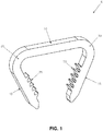
- a novel staple 5 which is able to bring bone fragments into close proximity with each other, generate a greater, and more uniform (i.e., across the cortical bone and the cancellous bone), compressive load across the fracture line, and maintain that greater, and more uniform, compressive load for a prolonged period of time while healing occurs.
- Novel staple 5 is preferably an integral, monolithic structure manufactured from a single piece of shape memory material (e.g., a material capable of exhibiting superelasticity and/or a temperature-induced shape change).
- the shape memory material may be a metal alloy (e.g., Nitinol) or a polymer (e.g., appropriately processed PEEK).
- Staple 5 is designed to reduce fractures and generate and maintain greater, and more uniform, compression between bone fragments to aid in fracture healing.
- Staple 5 comprises an elastic bridge 10 and two elastic legs 15. Bridge 10 and legs 15 meet at a pair of curved hinge regions 20 which are also elastic.
- Legs 15 may have barbed teeth 25 to help the legs of the staple grip into the bone after implantation (see below) and prevent the legs of the staple from working their way back out of the bone.
- legs 15 of staple 5 are bent inward with an angle of less than 90°.
- legs 15 extend at an angle of about 45° to the longitudinal axis of bridge 10 when in their unrestrained state.
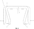
- bridge 10 of staple 5 Prior to implantation, bridge 10 of staple 5 can be reversibly strained outward (i.e., stretched longitudinally) and legs 15 of staple 5 can be reversibly bent to a position substantially perpendicular to bridge 10 ( Fig. 2 ) so as to allow for insertion of the legs of the staple into a prepared fracture site, with the stretched bridge of the staple spanning across the fracture line (see below).
- staple 5 is formed out of Nitinol, elastic deformations of up to approximately 8% are achievable.
- a delivery device can be used to strain bridge 10 and to bend legs 15, hold the staple in this strained state prior to implantation, and then insert the staple into the prepared fracture site.
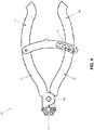
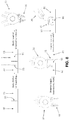
- FIGs. 4-7 there is shown an exemplary delivery device 30 which may be used to strain (i.e., stretch) bridge 10 and bend legs 15 of staple 5.
- Delivery device 30 comprises two arms 35 which are pivotally connected together at a pivot pin 40, whereby to provide a pair of handles 45 on one end for actuating the delivery device, and a staple mount 50 on the other end for holding and straining staple 5.
- staple mount 50 When staple 5 is mounted to staple mount 50 of delivery device 30 and handles 45 are thereafter moved toward one another, staple mount 50 translates apart, thus stretching bridge 10 of staple 5, and also bending legs 15 of staple 5 outward to a position substantially perpendicular to the longitudinal axis of bridge 10.
- Delivery device 30 preferably includes a locking feature 55 that facilitates holding staple 5 in its strained state and allows for easy insertion of staple 5 into a prepared fracture site (see below)
- locking feature 55 is preferably configured so that the surgeon can strain the staple to different degrees, thereby (i) enabling the surgeon to tailor the compressive force (e.g., by bending only legs 15, or by bending legs 15 and straining bridge 10), and (ii) enabling the surgeon to tailor the amount of recoverable strain established across the fracture line (e.g., by varying the amount that bridge 10 is stretched), depending on bone quality.
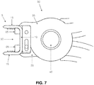
- Fig. 5 shows a close-up of staple mount 50 of delivery device 30.
- Staple mount 50 comprises a channel 60 that receives bridge 10 of staple 5, and two staple-stretching linkages 65 which sit distal to, and help define, channel 60.
- the radii 67 of staple-stretching linkages 65 mate with the curved hinge regions 20 of staple 5 when the legs 15 of the staple have been strained (i.e., bent) outward to a position substantially perpendicular to the longitudinal axis of bridge 10.
- Each staple-stretching linkage 65 is connected to the arms 35 by a pin 70.
- Pins 70 slide in a channels 75 provided on the staple-stretching linkages 65 (i.e., a first pin 70 mounted to a first staple-stretching linkage 65 slides in a channel 75 of the second staple-stretching linkage 65, and a second pin 70 mounted to the second staple-stretching linkage 65 slides in the channel 75 of the first staple-stretching linkage 65).
- Channels 75 are sized to limit the maximum amount of strain which may be imposed on bridge 10 of staple 5 by delivery device 30 (i.e., channels 75 limit the extent to which bridge 10 of staple 5 may be stretched).
- Figs. 6 and 7 show staple 5 being loaded onto delivery device 30 and staple 5 being strained, i.e., bridge 10 being stretched and legs 15 being bent so that they are perpendicular to the longitudinal axis of bridge 10. More particularly, Fig. 6 shows staple 5 loaded onto staple mount 50 of delivery device 30 while staple mount 50 of delivery device 30 is in its closed (i.e., non-staple-straining) position. This is done by positioning bridge 10 of staple 5 in channel 60 of staple mount 50. Note that in this position, legs 15 of staple 5 are in their unbiased, pointed inward position. Fig. 7 shows staple 5 after handles 45 of delivery device 30 have been moved together, so that staple mount 50 is in its open (i.e., staple-straining) position.
- the delivery device is constructed so that upon squeezing handles 45, the legs of the staple are first bent to perpendicular and then, when the legs of the staple are substantially perpendicular, the bridge of the staple is elongated.
- staple 5 is configured so that the force that is generated as staple 5 reconfigures (i.e., as bridge 10 foreshortens and legs 15 bend inward) is less than the "tear through" force of the bone receiving legs 15, i.e., staple 5 is specifically engineered so as to not "tear through” the bone tissue when attempting to reconfigure.
- Delivery device 30 preferably includes the aforementioned locking feature 55 which enables the surgeon to control the extent to which the staple is strained (e.g., to bend only the legs of the staple, or to both bend the legs of the staple and strain the bridge of the staple, and to control the extent to which the bridge is stretched), thereby allowing the surgeon to tailor the compressive forces and recoverable strain imposed on the anatomy, depending on bone quality.
- the compressive forces of staple 5 can be controlled by modulating the material properties of the staple and/or the geometry of the staple.
- a staple should, preferably, have between about 15% and 55% cold work to control the recovery force of the staple; however, other degrees of cold work may be used, and/or the material may not be cold worked at all.
- the shape memory material that the staple is made out of should, preferably, have an austenite finish temperature of greater than about -10°C, resulting in a temperature differential of about 47°C when the staple is implanted (assuming that the staple is implanted in a human body).
- Staple geometry also affects the compression forces generated.
- the staple legs are critical for transmitting the compression force to the bone without "tearing through” the bone.
- the height, width, and length of the staple legs, and the geometry of the staple legs, are all significant relative to the staple's ability to not "tear through” the bone. Staple legs with greater surface area are better able to distribute the compression force and thus not “tear through” the bone.
- Fig. 8 shows how staple 5 may be used to reduce a fracture and generate and maintain greater, and more uniform, compression between bone fragments 80 and 85 to aid in fracture healing.
- the fracture 90 to be fused is first re-approximated and reduced.
- a drill guide (not shown) of the sort well known in the art is used to drill two holes 95 the correct distance apart to accommodate the legs 15 of the strained staple 5.
- Staple 5 is loaded onto delivery device 30, and delivery device 30 is used to stretch bridge 10 and straighten legs 15 of staple 5 (i.e., by squeezing together handles 45). While still on delivery device 30, legs 15 of staple 5 are placed into the pre-drilled holes 95. Staple 5 is then released from delivery device 30, which allows the stretched bridge 10 of staple 5 to foreshorten so as to apply compression to the fracture line, and which allows the strained legs 15 of staple 5 to "kick in” and thereby apply additional inward pressure across the fracture line 90.
- staple 5 applies more uniform compression across the fracture site, generating compression across both the cortical and intramedullary surfaces, using the compressive forces generated by the foreshortening bridge 10 of the strained staple 5 and using the compressive forces generated by inwardly bending legs 15 of the strained staple 5.
- staple 5 can be used to attach soft tissue to bone (e.g., to attach a rotator cuff to bone).
- delivery device 30 may not always seat the staple with the bridge of the staple seated directly against the cortical surface of the bone (i.e., the bridge of the staple may sit slightly above the cortical surface of the bone). Therefore, a tamp of the sort well known in the art may be used to fully seat the staple bridge against the cortical surface of the bone.
- delivery device 30 may be constructed so that its staple-straining linkages 65 are each formed with an outboard constraint 97, whereby to prevent legs 15 from being bent past 90 degrees (relative to the longitudinal axis of bridge 10) when the staple is strained.
- staple 5 and delivery device 30 are provided in the form of a sterilized kit.
- the kit may include additional instruments to aid in the implantation of the staple (e.g., k-wire, drill bit, staple size guide, tamp, etc.).
- staple 5 is strained so that, upon deployment in the bone, it will provide compression across a fracture line.
- staple 5 can be configured to provide a distraction force to a bone.
- staple 5 can be configured and strained so that bridge 10 can be compressed, and/or legs 15 can be bent outward, such that when staple 5 is deployed in bone, the reconfiguring staple can apply a distraction force to the bone, whereby to cause the bone to grow and thereby elongate.
- staple 5 is manufactured from a shape memory material (e.g., a material capable of exhibiting superelasticity and/or a temperature-induced shape change).
- the shape memory material may be a metal alloy (e.g., Nitinol) or a polymer (e.g, appropriately processed PEEK).
- staple 5 can be manufactured out of a single piece of shape memory material (i.e., so as to create an integral, monolithic structure), and the different regions of the staple worked differently, in a metallurgical sense, so that different regions of the staple have different mechanical properties and exhibit different mechanical characteristics, even as they form a single, integral, monolithic structure.
- staple 5 can be manufactured so that bridge 10 is elastic, legs 15 are elastic, and curved hinge regions 20 are elastic, in which case bridge 10 can be elastically deformed, and legs 15 can be elastically deformed, so that both bridge 10 and legs 15 provide compression to the fracture site after implantation.
- bridge 10 and legs 15 may be worked, metallurgically, so that they have the same or different mechanical properties.
- staple 5 can be manufactured so that bridge 10 is malleable and non-superelastic (e.g., fully annealed Nitinol, or martensitic Nitinol with an austenite start temperature greater than body temperature), and legs 15 and hinge regions 20 are superelastic (e.g., austenite but capable of forming stress-induced martensite).
- This allows the malleable bridge 10 of staple 5 to be inelastically bent (i.e., to take a set) to accommodate a particular geometry of the cortical anatomy, while still allowing the superelastic legs 15 of the staple to generate compression.
- legs 15 of staple 5 may be manufactured at a more acute angle ( Fig. 10 ) so as to allow for adequate fracture compression and reduction in the event that bridge 10 must be bent downward (e.g., deformed to a concave position) to meet the anatomical structure of the cortical bone.
- FIG. 9 shows a monolithic staple 5 where bridge 10 is malleable and legs 15 are superelastic, and where staple 5 is shown in its unbent and unstrained condition; and Fig. 10 , where bridge 10 of staple 5 has been bent to give it an altered configuration.
- staple 5 shown in Figs. 9 and 10 is preferably formed out of a single piece of shape memory material, whereby to form a single, integral, monolithic structure, with the single piece of shape memory material having different regions of the staple worked differently, in a metallurgical sense, so that different regions of the staple have different mechanical properties and exhibit different mechanical characteristics, i.e., bridge 10 is malleable and legs 15 are superelastic.
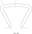
- staple 5 it may be desirable for staple 5 to start with a bridge that is convex, e.g., such as the staple 5 shown in Fig. 10A .
- a bridge that is convex
- the bridge of the implanted staple will sit flush with the cortical bone surface if the bone surface is largely planar.
- the resulting implanted staple could have two small "humps" at the outer ends of the bridge, i.e., at the bridge-hinge interface.
- a convex-shaped bridge i.e., such as is shown in Fig. 10A ) largely eliminates these "humps".
- staple 5 is formed out of a single piece of shape memory material (i.e., so as to form a single, integral, monolithic structure), with the shape memory material being worked so that bridge 10 is malleable (e.g., fully annealed Nitinol, or martensitic Nitinol with an austenite start temperature greater than body temperature) and legs 15 are superelastic (e.g., austenite but capable of forming stress-induced martensite), such that bridge 10 of staple 5 may be bent to contour to the surface of the bone while the compressive force generated by the superelastic legs 15 of the staple are used to help fuse the bone.
- shape memory material i.e., so as to form a single, integral, monolithic structure
- bridge 10 is malleable (e.g., fully annealed Nitinol, or martensitic Nitinol with an austenite start temperature greater than body temperature) and legs 15 are superelastic (e.g., austenite but capable
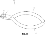
- a bending device can be used to bend bridge 10 of staple 5 prior to implantation of the staple.
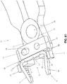
- An exemplary bending device 100 is shown in Fig. 11 .
- Bending device 100 is essentially a modified plier assembly. Staple 5 is placed into the bending fixture 105 of bending device 100; compressing the handles 110 causes bridge 10 of staple 5 to be bent to better meet the shape of the cortical bone surface.
- Fig. 12 shows a close-up of bending fixture 105 of bending device 100.
- Two pins 115 are used to locate the staple, and a third pin 120 is used to bend the bridge of the staple when the handles 110 of bending device 100 are compressed.
- a channel 125 in bending fixture 105 both directs the shape of the contour while also serving to limit the maximum bend imposed on the bridge of the staple.
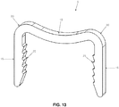
- the legs of the staple can be strained open (e.g., to the geometry shown in Fig. 13 ) so as to allow the bent, strained staple to be inserted into the prepared fracture site.
- the bent staple may be strained using a plier assembly 130 comprising a pair of handles 135 and a straining fixture 140. The previously-bent staple is placed into straining fixture 140, and compressing handles 135 causes the staple's legs 15 to be strained opened to parallel.
- Plier assembly 130 is also used to insert the staple into the bone after the legs of the staple have been strained open to substantially parallel.
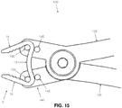
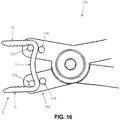
- Figs. 15 and 16 show the construction and function of straining fixture 140 in greater detail.
- Staple 5 is supported by two internal pins 145 and two external pins 150.
- Compressing handles 135 cause the staple legs to move from an inward-pointing configuration ( Fig. 15 ) to a more open (e.g., parallel) state ( Fig. 16 ).
- the previously-bent staple, with the legs now strained to the open state, is then ready for implantation across the fracture line.
- the strained legs 15 of staple 5 then kick inward, reducing the fracture and generating and maintaining compression across the fracture.
- Figs. 17 and 18 show how a staple formed out of a shape memory material, with its bridge being malleable (e.g., fully annealed Nitinol, or martensitic Nitinol with an austenite start temperature greater than body temperature) and its legs being superelastic (e.g., austenite but capable of forming stress-induced martensite), may be used to reduce a fracture 160 between two bone fragments 165, 170 and generate and maintain compression across the fracture.
- malleable e.g., fully annealed Nitinol, or martensitic Nitinol with an austenite start temperature greater than body temperature
- superelastic e.g., austenite but capable of forming stress-induced martensite
- the bridge of the staple is malleable and the legs of the staple are superelastic, the bridge of the staple can be first bent to match the surface profile of the bone while enabling the superelastic legs of the staple to be elastically strained to provide the compressive force across the fracture.
- staple 5 is first loaded onto bending device 100 and the bridge of the staple is bent to accommodate the surface profile of the patient's cortical bone anatomy.
- the surgeon may use fluoroscopy or trial-and-error to bend the bridge of the staple to the appropriate configuration.
- a drill guide (not shown) is used to drill holes 175 into the bone fragments 165, 170 at the appropriate locations on either side of the fracture line 160 to accommodate the strained staple legs.
- Staple 5 is then loaded onto plier assembly 130, and superelastic legs 15 are then elastically bent to the open state.
- the staple With the bridge of the staple inelastically bent into the appropriate configuration and with the legs of the staple elastically strained to substantially parallel, the staple can be inserted into the pre-drilled holes 175 in bone fragments 165, 170.
- the staple is then released from plier assembly 130 and tamped to sit flush with the cortical surface, with the inelastically bent bridge 10 of the staple more closely matching the surface contour of the bone.
- the elastically-strained superelastic legs 15 of the staple applies a compressive force across the fracture.
- the malleable bridge may be bent, or further bent, after the staple has been deployed in bone, e.g., to match, or to more closely match, the surface profile of the bone.
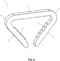
- the bone may have a convex profile.
- Fig. 19 there is shown a staple 5 which has been inelastically bent to have a convex bridge 10 and two legs 15.
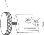
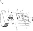
- Figs. 20 and 21 show another bending device 180 which may be used to bend the bridge of a staple, e.g., the bridge 10 of the staple 5 shown in Fig. 10A .
- Bending device 180 generally comprises a housing 185 supporting a pair of pins 190. Pins 190 receive staple 5 in the manner shown in Fig. 21 .
- Bending device 180 also comprises a screw mechanism 195 which selectively advances an element 200 toward pins 190 or retracts element 200 away from pins 190.
- screw mechanism 195 can be used to drive element 200 against bridge 10 of staple 5, whereby to bend the bridge of the staple.
- staple 5 can be used to attach soft tissue to bone (e.g., to attach a rotator cuff to bone).
- delivery device 130 discussed above may not always seat the staple with the bridge of the staple seated directly against the cortical surface of the bone (i.e., the bridge of the staple may sit slightly above the cortical surface of the bone). Therefore, a tamp of the sort well known in the art may be used to fully seat the staple bridge against the cortical surface of the bone.
- staple 5, bending device 100 and/or bending device 180, and delivery device (i.e., plier assembly) 130 are provided in the form of a sterilized kit.
- the kit may include additional instruments to aid in the implantation of the staple (e.g., k-wire, drill bit, staple size guide, tamp, etc.).
- Conventional shape memory staples typically generate between about 20N and about 120N of compressive force from the staple legs kicking inward.
- the novel staple of the present invention having a stretched bridge as described herein generates a compressive load of greater than the 20N to 120N generated by other like-sized conventional staples, thereby providing significantly increased compressive forces without tearing through or otherwise damaging the bone. Additionally, the compressive force provided by the stretched bridge staple of the present invention is more uniformly distributed across the fracture line (i.e., across the cortical bone and the cancellous bone).
Landscapes
- Health & Medical Sciences (AREA)
- Surgery (AREA)
- Life Sciences & Earth Sciences (AREA)
- Orthopedic Medicine & Surgery (AREA)
- Heart & Thoracic Surgery (AREA)
- Veterinary Medicine (AREA)
- Engineering & Computer Science (AREA)
- Biomedical Technology (AREA)
- Nuclear Medicine, Radiotherapy & Molecular Imaging (AREA)
- Medical Informatics (AREA)
- Molecular Biology (AREA)
- Animal Behavior & Ethology (AREA)
- General Health & Medical Sciences (AREA)
- Public Health (AREA)
- Neurology (AREA)
- Rheumatology (AREA)
- Surgical Instruments (AREA)
- Portable Nailing Machines And Staplers (AREA)
- Prostheses (AREA)
Applications Claiming Priority (3)
| Application Number | Priority Date | Filing Date | Title |
|---|---|---|---|
| US201361903820P | 2013-11-13 | 2013-11-13 | |
| PCT/US2014/065406 WO2015073642A1 (fr) | 2013-11-13 | 2014-11-13 | Agrafes pour générer et appliquer une compression à l'intérieur d'un corps |
| EP14861238.5A EP3068312A4 (fr) | 2013-11-13 | 2014-11-13 | Agrafes pour générer et appliquer une compression à l'intérieur d'un corps |
Related Parent Applications (1)
| Application Number | Title | Priority Date | Filing Date |
|---|---|---|---|
| EP14861238.5A Division EP3068312A4 (fr) | 2013-11-13 | 2014-11-13 | Agrafes pour générer et appliquer une compression à l'intérieur d'un corps |
Publications (2)
| Publication Number | Publication Date |
|---|---|
| EP3563776A2 true EP3563776A2 (fr) | 2019-11-06 |
| EP3563776A3 EP3563776A3 (fr) | 2020-08-05 |
Family
ID=53044398
Family Applications (3)
| Application Number | Title | Priority Date | Filing Date |
|---|---|---|---|
| EP14861238.5A Withdrawn EP3068312A4 (fr) | 2013-11-13 | 2014-11-13 | Agrafes pour générer et appliquer une compression à l'intérieur d'un corps |
| EP19177616.0A Pending EP3563776A3 (fr) | 2013-11-13 | 2014-11-13 | Agrafes pour générer et appliquer une compression à l'intérieur d'un corps |
| EP14862438.0A Active EP3068325B1 (fr) | 2013-11-13 | 2014-11-13 | Dispositifs intermédullaires permettant de générer et d'appliquer une compression à l'intérieur d'un corps |
Family Applications Before (1)
| Application Number | Title | Priority Date | Filing Date |
|---|---|---|---|
| EP14861238.5A Withdrawn EP3068312A4 (fr) | 2013-11-13 | 2014-11-13 | Agrafes pour générer et appliquer une compression à l'intérieur d'un corps |
Family Applications After (1)
| Application Number | Title | Priority Date | Filing Date |
|---|---|---|---|
| EP14862438.0A Active EP3068325B1 (fr) | 2013-11-13 | 2014-11-13 | Dispositifs intermédullaires permettant de générer et d'appliquer une compression à l'intérieur d'un corps |
Country Status (4)
| Country | Link |
|---|---|
| US (6) | US9855036B2 (fr) |
| EP (3) | EP3068312A4 (fr) |
| CN (2) | CN106413606B (fr) |
| WO (2) | WO2015073728A1 (fr) |
Cited By (5)
| Publication number | Priority date | Publication date | Assignee | Title |
|---|---|---|---|---|
| US11911036B2 (en) | 2021-05-17 | 2024-02-27 | Medline Industries, Lp | Staple instrument |
| US11937819B2 (en) | 2022-08-30 | 2024-03-26 | Medline Industries, Lp | Staple instrument |
| USD1027175S1 (en) | 2021-05-17 | 2024-05-14 | Medline Industries, Lp | Staple instrument |
| USD1027176S1 (en) | 2021-05-17 | 2024-05-14 | Medline Industries, Lp | Staple instrument |
| US12458346B2 (en) | 2023-04-05 | 2025-11-04 | Medline Industries, Lp | Staple instrument |
Families Citing this family (87)
| Publication number | Priority date | Publication date | Assignee | Title |
|---|---|---|---|---|
| US8388624B2 (en) | 2003-02-24 | 2013-03-05 | Arthrosurface Incorporated | Trochlear resurfacing system and method |
| CA2572584A1 (fr) | 2004-06-28 | 2006-01-12 | Arthrosurface, Inc. | Systeme de remplacement de surface articulaire |
| CA2686814A1 (fr) | 2006-12-11 | 2008-06-19 | Arthrosurface Incorporated | Appareil de resection retrograde et procede |
| US9662126B2 (en) | 2009-04-17 | 2017-05-30 | Arthrosurface Incorporated | Glenoid resurfacing system and method |
| WO2016154393A1 (fr) | 2009-04-17 | 2016-09-29 | Arthrosurface Incorporated | Système de réparation de glénoïde et ses méthodes d'utilisation |
| EP2542165A4 (fr) | 2010-03-05 | 2015-10-07 | Arthrosurface Inc | Système et procédé de resurfaçage tibial |
| EP3137645B1 (fr) * | 2011-09-22 | 2024-05-29 | Arthrex, Inc. | Régulation de la contrainte de décharge de dispositifs de nitinol |
| EP2804565B1 (fr) | 2011-12-22 | 2018-03-07 | Arthrosurface Incorporated | Système pour une fixation osseuse |
| US8584853B2 (en) | 2012-02-16 | 2013-11-19 | Biomedical Enterprises, Inc. | Method and apparatus for an orthopedic fixation system |
| WO2014008126A1 (fr) | 2012-07-03 | 2014-01-09 | Arthrosurface Incorporated | Système et procédé de resurfaçage et de réparation d'articulation |
| US9492200B2 (en) | 2013-04-16 | 2016-11-15 | Arthrosurface Incorporated | Suture system and method |
| EP3068312A4 (fr) | 2013-11-13 | 2017-07-26 | Mx Orthopedics, Corp. | Agrafes pour générer et appliquer une compression à l'intérieur d'un corps |
| JP2017501002A (ja) | 2013-12-20 | 2017-01-12 | クロスローズ エクストリミティ システムズ リミテッド ライアビリティ カンパニー | 多軸ロッキング穴 |
| US10624748B2 (en) | 2014-03-07 | 2020-04-21 | Arthrosurface Incorporated | System and method for repairing articular surfaces |
| US11607319B2 (en) | 2014-03-07 | 2023-03-21 | Arthrosurface Incorporated | System and method for repairing articular surfaces |
| US9962265B2 (en) | 2014-03-07 | 2018-05-08 | Arthrosurface Incorporated | System and method for repairing articular surfaces |
| US10456130B2 (en) * | 2014-05-07 | 2019-10-29 | Biomedical Enterprises, Inc. | Method and apparatus for loading and implanting a shape memory implant |
| US10456131B2 (en) | 2014-05-07 | 2019-10-29 | Biomedical Enterprises, Inc. | Method and apparatus for loading and implanting a shape memory implant |
| US11202626B2 (en) | 2014-07-10 | 2021-12-21 | Crossroads Extremity Systems, Llc | Bone implant with means for multi directional force and means of insertion |
| US10492841B2 (en) | 2014-07-10 | 2019-12-03 | Crossroads Extremity Systems, Llc | Bone implant and means of insertion |
| USD780311S1 (en) * | 2014-11-20 | 2017-02-28 | Biomedical Enterprises, Inc. | Orthopedic implant |
| WO2016130842A1 (fr) * | 2015-02-14 | 2016-08-18 | In2Bones Usa, Llc | Instrument pliant chirurgical |
| US10863982B2 (en) * | 2016-02-11 | 2020-12-15 | In2Bones Usa, Llc | Surgical bending instrument |
| EP3988032A3 (fr) * | 2015-02-14 | 2022-05-18 | In2Bones USA, LLC | Instrument de cintrage chirurgical |
| US12490978B2 (en) | 2015-02-24 | 2025-12-09 | Orthovestments, Llc | Orthopedic bone staple with polyaxial compression capability |
| WO2016154417A1 (fr) | 2015-03-24 | 2016-09-29 | Mẍ Orthopedics, Corp. | Agrafes pour générer et appliquer une compression dans un corps |
| US10383625B1 (en) | 2015-06-30 | 2019-08-20 | Miguel Angel Pirela-Cruz | Scaphoid fixation with an anatomically designed staple |
| JP6560434B2 (ja) | 2015-07-13 | 2019-08-14 | クロスローズ エクストリミティ システムズ リミテッド ライアビリティ カンパニー | 動的要素を備える骨プレート |
| WO2017040732A2 (fr) | 2015-09-03 | 2017-03-09 | Biomedical Enterprises, Inc. | Implant orthopédique élastique et procédé pour le fabriquer |
| EP3413807B1 (fr) * | 2016-02-08 | 2023-08-16 | Acumed LLC | Agrafes de fixation à utiliser dans des procédures chirurgicales |
| JP6951351B2 (ja) | 2016-02-08 | 2021-10-20 | クロスローズ エクストリミティ システムズ エルエルシーCrossroads Extremity Systems, Llc | インプラント挿入器 |
| US10188388B2 (en) * | 2016-02-16 | 2019-01-29 | Andronica Shontay Mandell Handie | Surgical staple insertion device |
| EP3426166B1 (fr) * | 2016-03-07 | 2025-03-19 | Arthrex, Inc | Dispositifs de production et d'application une compression à l'intérieur d'un corps |
| US10779816B2 (en) * | 2016-07-07 | 2020-09-22 | Medline Industries, Inc. | Orthopedic implant, method, and kit |
| US11864753B2 (en) | 2017-02-06 | 2024-01-09 | Crossroads Extremity Systems, Llc | Implant inserter |
| WO2018148284A1 (fr) | 2017-02-07 | 2018-08-16 | Crossroads Extremity Systems, Llc | Implant à contre-couple |
| USD865178S1 (en) * | 2017-06-02 | 2019-10-29 | Vincent James Sammarco | Orthopedic clip |
| US9993246B1 (en) | 2017-07-07 | 2018-06-12 | Endure Enterprises, Pllc | Medical device bending devices and methods of use |
| US10888319B2 (en) | 2017-07-10 | 2021-01-12 | Gramercy Extremity Orthopedics Llc | Bone staple insertion tool and related method |
| USD870284S1 (en) | 2017-07-31 | 2019-12-17 | Crossroads Extremity Systems, Llc | Osteosynthesis clip |
| US11160663B2 (en) | 2017-08-04 | 2021-11-02 | Arthrosurface Incorporated | Multicomponent articular surface implant |
| US10842487B2 (en) * | 2017-10-20 | 2020-11-24 | Biomedical Enterprises, Inc. | Method and apparatus for loading and implanting a shape memory implant |
| US11000281B2 (en) | 2017-12-22 | 2021-05-11 | Ortho Solutions Holdings Limited | Bone staple inserter |
| US10987101B2 (en) | 2017-12-22 | 2021-04-27 | Ortho Solutions Holdings Limited | Superelastic bone compression staple |
| US20190357951A1 (en) | 2018-05-22 | 2019-11-28 | Subluxation Safe Asset, LP | Staple and plate hard tissue fixation |
| EP3801298A4 (fr) * | 2018-05-29 | 2022-03-09 | In2Bones USA, LLC | Instrument à plier chirurgical |
| CN108771562B (zh) * | 2018-06-01 | 2020-04-14 | 温州医科大学附属第二医院、温州医科大学附属育英儿童医院 | 小骨折块固定u型骨钉 |
| US11000323B2 (en) | 2018-06-01 | 2021-05-11 | Ortho Solutions Holdings Limited | Claw foot bone plate and plate inserter system with fixed and active compression, and method for its use |
| US11135030B2 (en) | 2018-06-15 | 2021-10-05 | Verb Surgical Inc. | User interface device having finger clutch |
| USD895113S1 (en) | 2018-08-08 | 2020-09-01 | Medshape, Inc. | Low profile staple |
| US11116499B1 (en) * | 2018-08-08 | 2021-09-14 | Medshape, Inc. | Low profile staple and methods for using the same |
| USD957636S1 (en) | 2018-08-08 | 2022-07-12 | Medshape, Inc. | Low profile staple |
| US10307156B1 (en) * | 2018-08-08 | 2019-06-04 | Medshape, Inc. | Low profile staple and methods for using same |
| USD1024332S1 (en) | 2018-08-08 | 2024-04-23 | Medshape, Inc. | Low profile staple |
| USD1081989S1 (en) | 2018-08-08 | 2025-07-01 | Medshape, Inc. | Low profile staple |
| US20200046345A1 (en) * | 2018-08-13 | 2020-02-13 | Thomas Zink | Variable Compression Bone Staple System |
| US11504172B2 (en) | 2018-11-01 | 2022-11-22 | Arthrex, Inc. | Variable stiffness hammertoe K-wire and methods for use |
| US11478358B2 (en) | 2019-03-12 | 2022-10-25 | Arthrosurface Incorporated | Humeral and glenoid articular surface implant systems and methods |
| US11439445B2 (en) * | 2019-03-19 | 2022-09-13 | Dynorif, Llc | Methods of bone reduction and fixation |
| WO2021034799A1 (fr) * | 2019-08-19 | 2021-02-25 | Ortho Solutions Holdings Limited | Dispositif d'insertion d'agrafe osseuse de type seringue |
| CN110801255A (zh) * | 2019-11-18 | 2020-02-18 | 北京市春立正达医疗器械股份有限公司 | 一种门型钉 |
| US12042386B2 (en) | 2020-01-29 | 2024-07-23 | DePuy Synthes Products, Inc. | Shape memory implants and methods and apparatus for the loading and implanting thereof |
| US11523820B2 (en) | 2020-01-29 | 2022-12-13 | DePuy Synthes Products, Inc. | Shape memory implants and a method and apparatus for the loading and implanting thereof |
| EP4103069A4 (fr) | 2020-02-11 | 2024-06-05 | Embody Inc. | Dispositif d'ancrage chirurgical, dispositif de déploiement et méthode d'utilisation |
| US11642124B2 (en) | 2020-06-16 | 2023-05-09 | Ortho Solutions Holdings Limited | Reinforced bridge superelastic bone compression staple and inserter system |
| US11806059B2 (en) | 2020-07-14 | 2023-11-07 | DePuy Synthes Products, Inc. | Shape memory implants and methods and apparatus for the loading and implanting thereof |
| US12059183B2 (en) | 2020-07-31 | 2024-08-13 | Crossroads Extremity Systems, Llc | Bone plates with dynamic elements and screws |
| US11690616B2 (en) * | 2020-10-16 | 2023-07-04 | Arthrex, Inc. | Orthopedic staple insertion |
| USD961081S1 (en) | 2020-11-18 | 2022-08-16 | Crossroads Extremity Systems, Llc | Orthopedic implant |
| US11311289B1 (en) | 2021-06-21 | 2022-04-26 | Pressio Inc. | Compression and fixation systems and processes for using the same |
| USD977640S1 (en) | 2021-06-21 | 2023-02-07 | Pressio, Inc. | Staple instrument |
| USD998147S1 (en) | 2021-06-21 | 2023-09-05 | Pressio, Inc. | Boring tool handle |
| USD996480S1 (en) | 2021-06-21 | 2023-08-22 | Pressio Inc. | Boring tool |
| USD1003436S1 (en) * | 2021-08-19 | 2023-10-31 | Medline Industries, Lp | Surgical staple |
| US12220123B2 (en) | 2021-08-19 | 2025-02-11 | Medline Industries, Lp | Apparatus and methods for joining bones |
| US12295625B2 (en) | 2021-08-19 | 2025-05-13 | Medline Industries, Lp | Apparatus and methods for joining bones |
| USD1004088S1 (en) | 2021-08-19 | 2023-11-07 | Medline Industries, Lp | Surgical staple |
| US11931084B2 (en) | 2021-12-07 | 2024-03-19 | DePuy Synthes Products, Inc. | Method and apparatus for an orthopedic fixation system |
| CN114145829B (zh) * | 2021-12-08 | 2023-05-23 | 韩延明 | 一种管状骨骨折可吸收材料髓内固定系统 |
| WO2023159181A1 (fr) * | 2022-02-18 | 2023-08-24 | Kitotech Medical, Inc. | Agrafes et instruments pour peau profonde à modulation de force |
| US12064156B2 (en) | 2023-01-09 | 2024-08-20 | John F. Krumme | Dynamic compression fixation devices |
| USD1017038S1 (en) * | 2022-05-02 | 2024-03-05 | Concise Engineering, Inc. | Bone staple |
| USD1101943S1 (en) | 2022-05-02 | 2025-11-11 | Concise Engineering, Inc. | Bone staple inserter |
| US12446938B2 (en) | 2023-01-12 | 2025-10-21 | DePuy Synthes Products, Inc. | Orthopedic fixation system |
| US12336704B2 (en) | 2023-01-13 | 2025-06-24 | Medline Industries, Lp | Apparatus and methods for joining bones |
| US12376850B2 (en) | 2023-06-22 | 2025-08-05 | Medline Industries, Lp | Surgical staple |
| US12453552B1 (en) | 2024-11-28 | 2025-10-28 | Vilex Llc | Compression staple systems and methods |
Family Cites Families (148)
| Publication number | Priority date | Publication date | Assignee | Title |
|---|---|---|---|---|
| US2580821A (en) | 1950-10-21 | 1952-01-01 | Nicola Toufick | Spring impactor bone plate |
| US3960147A (en) | 1975-03-10 | 1976-06-01 | Murray William M | Compression bone staples and methods of compressing bone segments |
| GB1565178A (en) | 1977-02-24 | 1980-04-16 | Interfix Ltd | Bone screw |
| US4263903A (en) | 1979-01-08 | 1981-04-28 | Richards Manufacturing Co., Inc. | Medical staple means |
| US4428376A (en) * | 1980-05-02 | 1984-01-31 | Ethicon Inc. | Plastic surgical staple |
| CA1149106A (fr) | 1980-11-10 | 1983-07-05 | Henk W. Wevers | Clip orthopedique |
| IL64726A (en) * | 1982-01-08 | 1985-02-28 | Samuel Lieberson | Surgical staple for fractured bones |
| US4438769A (en) | 1982-04-15 | 1984-03-27 | Pratt Clyde R | Medical staple device |
| US4512338A (en) | 1983-01-25 | 1985-04-23 | Balko Alexander B | Process for restoring patency to body vessels |
| US4503569A (en) | 1983-03-03 | 1985-03-12 | Dotter Charles T | Transluminally placed expandable graft prosthesis |
| US4570623A (en) * | 1983-06-02 | 1986-02-18 | Pfizer Hospital Products Group Inc. | Arched bridge staple |
| US5190546A (en) | 1983-10-14 | 1993-03-02 | Raychem Corporation | Medical devices incorporating SIM alloy elements |
| US4733665C2 (en) | 1985-11-07 | 2002-01-29 | Expandable Grafts Partnership | Expandable intraluminal graft and method and apparatus for implanting an expandable intraluminal graft |
| DE3640745A1 (de) | 1985-11-30 | 1987-06-04 | Ernst Peter Prof Dr M Strecker | Katheter zum herstellen oder erweitern von verbindungen zu oder zwischen koerperhohlraeumen |
| SE453258B (sv) | 1986-04-21 | 1988-01-25 | Medinvent Sa | Elastisk, sjelvexpanderande protes samt forfarande for dess framstellning |
| US4905679A (en) | 1988-02-22 | 1990-03-06 | M P Operation, Inc. | Bone fracture reduction device and method of internal fixation of bone fractures |
| US4858601A (en) | 1988-05-27 | 1989-08-22 | Glisson Richard R | Adjustable compression bone screw |
| US4959064A (en) | 1988-10-07 | 1990-09-25 | Boehringer Mannheim Corporation | Dynamic tension bone screw |
| US4950227A (en) | 1988-11-07 | 1990-08-21 | Boston Scientific Corporation | Stent delivery system |
| US4959065A (en) | 1989-07-14 | 1990-09-25 | Techmedica, Inc. | Bone plate with positioning member |
| US5026390A (en) | 1989-10-26 | 1991-06-25 | Brown Alan W | Surgical staple |
| US5089006A (en) | 1989-11-29 | 1992-02-18 | Stiles Frank B | Biological duct liner and installation catheter |
| US5044540A (en) | 1990-03-05 | 1991-09-03 | Micro Precision, Inc. | Surgical stapling instrument |
| FR2668361A1 (fr) | 1990-10-30 | 1992-04-30 | Mai Christian | Agrafe et plaque d'osteosynthese a compression dynamique auto-retentive. |
| US5098434A (en) | 1990-11-28 | 1992-03-24 | Boehringer Mannheim Corporation | Porous coated bone screw |
| FR2700464B1 (fr) | 1992-11-13 | 1995-04-14 | Maurice Bertholet | Pièce de liaison pour éléments osseux. |
| US6030162A (en) | 1998-12-18 | 2000-02-29 | Acumed, Inc. | Axial tension screw |
| FR2710254B1 (fr) | 1993-09-21 | 1995-10-27 | Mai Christian | Agrafe d'ostéosynthèse multi-branches à compression dynamique autorétentive. |
| CA2148667A1 (fr) | 1994-05-05 | 1995-11-06 | Carlo A. Mililli | Appareil chirurgical electrique autonome |
| WO1996016603A1 (fr) * | 1994-11-28 | 1996-06-06 | Creighton University | Agrafe hemostatique a memoire de forme |
| US5782919A (en) * | 1995-03-27 | 1998-07-21 | Sdgi Holdings, Inc. | Interbody fusion device and method for restoration of normal spinal anatomy |
| US5634926A (en) * | 1995-04-25 | 1997-06-03 | Jobe; Richard P. | Surgical bone fixation apparatus |
| US5607530A (en) | 1995-08-09 | 1997-03-04 | W.E. Hall Company | Polymer diverter system for metal pipe having an integrally formed polymer liner |
| US5899906A (en) | 1996-01-18 | 1999-05-04 | Synthes (U.S.A.) | Threaded washer |
| FR2752720A1 (fr) | 1996-09-03 | 1998-03-06 | Medinov Amp | Support d'agrafe chirurgicale du type elastique, superelastique ou a memoire de forme |
| US5766218A (en) | 1996-10-01 | 1998-06-16 | Metamorphic Surgical Devices, Inc. | Surgical binding device and method of using same |
| US5947999A (en) | 1996-12-03 | 1999-09-07 | Groiso; Jorge A. | Surgical clip and method |
| ATE249175T1 (de) | 1997-02-28 | 2003-09-15 | Synthes Ag | Implantat für die osteosynthese |
| IL121316A (en) | 1997-07-15 | 2001-07-24 | Litana Ltd | A medical device for planting in an alloy body with memory properties |
| FR2787313B1 (fr) | 1998-12-17 | 2001-05-04 | Orsco Internat | Implant d'osteosynthese |
| US6569173B1 (en) | 1999-12-14 | 2003-05-27 | Integrated Vascular Interventional Technologies, L.C. | Compression plate anastomosis apparatus |
| US6325805B1 (en) | 1999-04-23 | 2001-12-04 | Sdgi Holdings, Inc. | Shape memory alloy staple |
| US6059787A (en) | 1999-04-26 | 2000-05-09 | Allen; Drew | Compression bone staple apparatus and method |
| US6607530B1 (en) | 1999-05-10 | 2003-08-19 | Highgate Orthopedics, Inc. | Systems and methods for spinal fixation |
| ES2211583T3 (es) | 1999-09-13 | 2004-07-16 | Synthes Ag Chur | Sistema de placa osea. |
| US7491236B2 (en) | 2000-02-16 | 2009-02-17 | Trans1, Inc. | Dual anchor prosthetic nucleus apparatus |
| US6533157B1 (en) | 2000-02-22 | 2003-03-18 | Power Medical Interventions, Inc. | Tissue stapling attachment for use with an electromechanical driver device |
| US20050043757A1 (en) | 2000-06-12 | 2005-02-24 | Michael Arad | Medical devices formed from shape memory alloys displaying a stress-retained martensitic state and method for use thereof |
| EP1294298B1 (fr) | 2000-06-26 | 2004-11-10 | SYNTHES AG Chur | Plaque osseuse pour osteosynthese |
| US6767356B2 (en) * | 2000-09-01 | 2004-07-27 | Angiolink Corporation | Advanced wound site management systems and methods |
| IL138320A (en) | 2000-09-07 | 2005-11-20 | Niti Alloys Tech Ltd | Staples for bone fixation |
| US7976648B1 (en) | 2000-11-02 | 2011-07-12 | Abbott Cardiovascular Systems Inc. | Heat treatment for cold worked nitinol to impart a shape setting capability without eventually developing stress-induced martensite |
| US20020111641A1 (en) * | 2001-01-08 | 2002-08-15 | Incisive Surgical, Inc. | Bioabsorbable surgical clip with engageable expansion structure |
| US6306140B1 (en) | 2001-01-17 | 2001-10-23 | Synthes (Usa) | Bone screw |
| DE10129490A1 (de) | 2001-06-21 | 2003-01-02 | Helmut Mueckter | Implantierbare Schraube zur Stabilisierung einer Gelenkverbindung oder eines Knochenbruches |
| US7175655B1 (en) | 2001-09-17 | 2007-02-13 | Endovascular Technologies, Inc. | Avoiding stress-induced martensitic transformation in nickel titanium alloys used in medical devices |
| US8702768B2 (en) | 2001-10-18 | 2014-04-22 | Orthoip, Llc | Cannulated bone screw system and method |
| US6656184B1 (en) | 2002-01-09 | 2003-12-02 | Biomet, Inc. | Bone screw with helical spring |
| US7618441B2 (en) | 2002-01-22 | 2009-11-17 | Jorge Abel Groiso | Bone staple and methods for correcting spine disorders |
| DE60314235T2 (de) | 2002-02-26 | 2008-01-31 | Degima Medizinprodukte Gmbh | Gewindevorrichtung mit verbessertem widerstand gegen durch torsion verursachtes brechen |
| US7229452B2 (en) | 2002-04-22 | 2007-06-12 | Tyco Healthcare Group Lp | Tack and tack applier |
| US6761731B2 (en) | 2002-06-28 | 2004-07-13 | Cordis Corporation | Balloon-stent interaction to help reduce foreshortening |
| US7955388B2 (en) | 2006-11-01 | 2011-06-07 | Acumed Llc | Orthopedic connector system |
| US7811312B2 (en) | 2002-12-04 | 2010-10-12 | Morphographics, Lc | Bone alignment implant and method of use |
| US7240677B2 (en) | 2003-02-03 | 2007-07-10 | Biomedical Enterprises, Inc. | System and method for force, displacement, and rate control of shaped memory material implants |
| WO2004069031A2 (fr) | 2003-02-03 | 2004-08-19 | Kinetikos Medical Incorporated | Appareils a vis de compression, systemes et procedes associes |
| US7044953B2 (en) | 2003-02-27 | 2006-05-16 | Stryker Leibinger Gmbh & Co. Kg | Compression bone screw |
| US7695471B2 (en) | 2003-04-18 | 2010-04-13 | The University Of Hong Kong | Fixation device |
| US20040260377A1 (en) | 2003-06-17 | 2004-12-23 | Medinol, Ltd. | Shape memory alloy endoprosthesis delivery system |
| US7635367B2 (en) | 2003-08-05 | 2009-12-22 | Medicrea International | Osteosynthesis clip and insertion tool for use with bone tissue fragments |
| US7481832B1 (en) | 2003-09-09 | 2009-01-27 | Biomet Sports Medicine, Llc | Method and apparatus for use of a self-tapping resorbable screw |
| EP1708629A4 (fr) | 2004-01-08 | 2011-08-17 | David Mark Allison | Dispositif de fixation d'os |
| US7297146B2 (en) | 2004-01-30 | 2007-11-20 | Warsaw Orthopedic, Inc. | Orthopedic distraction implants and techniques |
| DE102004009429A1 (de) | 2004-02-24 | 2005-09-22 | Biedermann Motech Gmbh | Knochenverankerungselement |
| FR2868938B1 (fr) * | 2004-04-16 | 2006-07-07 | Memometal Technologies Soc Par | Pince permettant la mise en place d'une agrafe d'osteosynthese de type superelastique |
| US7985222B2 (en) | 2004-04-21 | 2011-07-26 | Medshape Solutions, Inc. | Osteosynthetic implants and methods of use and manufacture |
| ATE481044T1 (de) * | 2004-05-21 | 2010-10-15 | Myers Surgical Solutions Llc | Frakturfixations- und situsstabilisationssystem |
| US7175626B2 (en) | 2004-06-15 | 2007-02-13 | Board Of Regents Of The University Of Nebraska | Dynamic compression device and driving tool |
| EP1611850A1 (fr) | 2004-06-28 | 2006-01-04 | Cardio Life Research S.A. | Dispositif d'occlusion et de ponction étanche pour structure anatomique. |
| FR2874166B1 (fr) | 2004-08-11 | 2012-03-30 | Surge Foot | Agrafe chirurgicale |
| US20060058796A1 (en) | 2004-09-14 | 2006-03-16 | Hartdegen Vernon R | Compression brace |
| WO2007001392A2 (fr) | 2004-10-01 | 2007-01-04 | The Regents Of The University Of Michigan | Fabrication de structures et de materiaux cellulaires en alliage a memoire de forme par assemblage reactif en phase liquide transitoire |
| WO2006104823A2 (fr) | 2005-03-25 | 2006-10-05 | Gordon, Richard, F. | Procede de production d'austenite induite par la contrainte |
| US7993380B2 (en) | 2005-03-31 | 2011-08-09 | Alphatel Spine, Inc. | Active compression orthopedic plate system and method for using the same |
| US20060264954A1 (en) | 2005-04-07 | 2006-11-23 | Sweeney Thomas M Ii | Active compression screw system and method for using the same |
| CN1907238B (zh) * | 2005-08-04 | 2012-02-22 | J·A·格鲁瓦索 | 骨综合夹及包括骨综合夹的外科手术系统 |
| EP1825826B1 (fr) | 2006-02-23 | 2008-08-06 | BIEDERMANN MOTECH GmbH | Dispositif d'ancrage osseux |
| US8147531B2 (en) | 2006-03-17 | 2012-04-03 | Tornier, Inc. | Compression pin with opposed threaded regions |
| WO2007117571A2 (fr) | 2006-04-06 | 2007-10-18 | Lotus Medical, Llc | UTILISATION de la compression active pour favoriser la guerison osseuse |
| WO2007134248A1 (fr) * | 2006-05-12 | 2007-11-22 | Cordis Corporation | Système d'ancrage osseux et son procédé d'utilisation |
| FR2901119B1 (fr) | 2006-05-19 | 2008-12-12 | Memometal Technologies Soc Par | Dispositif support d'un implant chirurgical a memoire de forme |
| US8205782B2 (en) | 2006-07-12 | 2012-06-26 | Niti Surgical Solutions Ltd. | Compression assemblies and applicators for use therewith |
| US20080065154A1 (en) | 2006-09-08 | 2008-03-13 | Warsaw Orthopedic, Inc | Surgical staple |
| US8721646B2 (en) | 2006-10-10 | 2014-05-13 | William Casey Fox | Methods and apparatus for a staple |
| FR2908626B1 (fr) | 2006-11-16 | 2010-01-15 | Newdeal | Implant d'arthrodese inter-phalangienne,kit chirurgical et procede de fabrication correspondants |
| US20080234763A1 (en) | 2007-03-16 | 2008-09-25 | Patterson Chad J | Surgical compression bone screw |
| FR2913876B1 (fr) | 2007-03-20 | 2009-06-05 | Memometal Technologies Soc Par | Dispositif d'osteosynthese |
| US20080249574A1 (en) | 2007-03-20 | 2008-10-09 | Mccombs Mary | Bone Screw System |
| KR101570213B1 (ko) | 2007-12-17 | 2015-11-18 | 신세스 게엠바하 | 동적 뼈 고정 요소 및 그 사용 방법 |
| FR2926453B1 (fr) * | 2008-01-17 | 2011-03-18 | Warsaw Orthopedic Inc | Dispositif d'osteosynthese rachidienne |
| US20090198287A1 (en) | 2008-02-04 | 2009-08-06 | Mark Hsien Nien Chiu | Bone fixation device and method of use thereof |
| WO2009103085A1 (fr) | 2008-02-14 | 2009-08-20 | Arizona Heart Innovative Technologies, Llc | Dispositif de fusion d’articulations |
| US8864804B2 (en) | 2008-02-14 | 2014-10-21 | Lloyd P. Champagne | Bent dip fusion screw |
| FR2929499B1 (fr) | 2008-04-02 | 2010-05-14 | Tornier Sa | Agrafe de compression. |
| US20090264937A1 (en) | 2008-04-21 | 2009-10-22 | Zimmer, Inc. | Bone screw for providing dynamic tension |
| US8808294B2 (en) | 2008-09-09 | 2014-08-19 | William Casey Fox | Method and apparatus for a multiple transition temperature implant |
| WO2010051289A1 (fr) | 2008-10-27 | 2010-05-06 | University Of Toledo | Ensemble fixation avec insert expansible |
| US20100211115A1 (en) | 2008-12-24 | 2010-08-19 | Jeff Tyber | Compression screw assembly, an orthopedic fixation system including a compression screw assembly and method of use |
| US8801732B2 (en) | 2009-01-26 | 2014-08-12 | Ethicon Endo-Surgery, Inc. | Surgical stapler to secure a tissue fold |
| FR2941859B1 (fr) | 2009-02-09 | 2012-04-06 | Memometal Technologies | Vis d'osteosynthese. |
| US20110144703A1 (en) | 2009-02-24 | 2011-06-16 | Krause William R | Flexible Screw |
| AU2010226273A1 (en) | 2009-03-19 | 2011-10-06 | Core Essence Orthopaedics, Inc. | Method and apparatus for delivering a shape memory article to a surgical site |
| JP2012531240A (ja) | 2009-06-26 | 2012-12-10 | クイックリング メディカル テクノロジーズ リミテッド | 外科用ステープラーおよび外科用ステープリングの方法 |
| CA2781435A1 (fr) | 2009-12-11 | 2011-06-16 | Synthes Usa, Llc | Ensemble de fixation d'os |
| FR2957244B1 (fr) | 2010-03-09 | 2012-04-13 | Synchro Medical | Implant d'arthrodese |
| US8216398B2 (en) | 2010-05-17 | 2012-07-10 | Saint Louis University | Method for controlling phase transformation temperature in metal alloy of a device |
| US8790379B2 (en) | 2010-06-23 | 2014-07-29 | Zimmer, Inc. | Flexible plate fixation of bone fractures |
| CN102068300B (zh) * | 2010-12-31 | 2012-10-10 | 任绍东 | 骨折治疗牵引弓 |
| WO2013013069A1 (fr) * | 2011-07-19 | 2013-01-24 | Illuminoss Medical, Inc. | Dispositifs photodynamiques en combinaison |
| US9339268B2 (en) | 2011-07-27 | 2016-05-17 | William Casey Fox | Bone staple, instrument and method of use and manufacturing |
| US9451957B2 (en) * | 2011-07-27 | 2016-09-27 | William Casey Fox | Bone staple extrusion instrument and method of use and manufacturing |
| EP3137645B1 (fr) | 2011-09-22 | 2024-05-29 | Arthrex, Inc. | Régulation de la contrainte de décharge de dispositifs de nitinol |
| US9283006B2 (en) | 2011-09-22 | 2016-03-15 | Mx Orthopedics, Corp. | Osteosynthetic shape memory material intramedullary bone stent and method for treating a bone fracture using the same |
| HK1201138A1 (en) | 2011-10-10 | 2015-08-28 | William Casey Fox | Shape changing bone implant for enhanced healing |
| US10064618B2 (en) | 2012-01-20 | 2018-09-04 | Zimmer, Inc. | Compression bone staple |
| US8584853B2 (en) | 2012-02-16 | 2013-11-19 | Biomedical Enterprises, Inc. | Method and apparatus for an orthopedic fixation system |
| US10292743B2 (en) | 2012-03-01 | 2019-05-21 | Wright Medical Technology, Inc. | Surgical staple |
| US9138274B1 (en) | 2012-05-04 | 2015-09-22 | Xtraverse, LLC | Fasteners with shape changing bellows and methods using same |
| EP2662667B1 (fr) | 2012-05-10 | 2016-01-06 | EM Microelectronic-Marin SA | Procédé de mesure d'un paramètre physique et circuit électronique d'interface d'un capteur capacitif pour sa mise en oeuvre |
| US9095338B2 (en) | 2012-10-09 | 2015-08-04 | Wright Medical Technology, Inc. | Surgical staple insertion device |
| EP2740428B1 (fr) | 2012-12-05 | 2019-05-08 | Biedermann Technologies GmbH & Co. KG | Élément d'ancrage osseux dynamique et procédé de fabrication d'un élément d'ancrage osseux dynamique |
| FR2999069B1 (fr) | 2012-12-06 | 2016-03-11 | In2Bones | Agrafe de compression a jambes convergentes |
| US9402624B1 (en) | 2013-03-14 | 2016-08-02 | Ascension Orthopedics, Inc. | Bone fixation staple |
| US9486212B2 (en) | 2013-03-15 | 2016-11-08 | Orthohelix Surgical Designs, Inc. | Bone staple storage, inserter, and method for use therewith |
| US9585656B2 (en) | 2013-06-03 | 2017-03-07 | Biomedical Enterprises, Inc. | Method and apparatus for loading and implanting a shape memory implant |
| EP3068312A4 (fr) | 2013-11-13 | 2017-07-26 | Mx Orthopedics, Corp. | Agrafes pour générer et appliquer une compression à l'intérieur d'un corps |
| FR3016510B1 (fr) | 2014-01-20 | 2018-04-20 | Arthroplastie Diffusion | Instrument chirurgical pour poser une agrafe d’osteosynthese |
| US10070904B2 (en) | 2014-02-21 | 2018-09-11 | Jeko Metodiev Madjarov | Bone fixation implants |
| US9408647B2 (en) | 2014-02-27 | 2016-08-09 | Biomedical Enterprises, Inc. | Method and apparatus for use of a compressing plate |
| WO2016028784A1 (fr) | 2014-08-19 | 2016-02-25 | Cronen Geoffrey | Système de fixation circonférentielle de la colonne vertébrale |
| US9883897B2 (en) | 2014-09-25 | 2018-02-06 | Biomedical Enterprises, Inc. | Method and apparatus for a compressing plate |
| US10299845B2 (en) | 2014-10-03 | 2019-05-28 | Alphatec Spine, Inc. | Orthopedic screw |
| US20170340777A1 (en) | 2014-11-14 | 2017-11-30 | The Texas A&M University System | Shape Memory Alloy Orthopedic Implant |
| US9901338B2 (en) | 2014-11-19 | 2018-02-27 | Biomet Manufacturing, Llc | Shape memory compression staple |
| WO2016130842A1 (fr) | 2015-02-14 | 2016-08-18 | In2Bones Usa, Llc | Instrument pliant chirurgical |
| WO2016154417A1 (fr) | 2015-03-24 | 2016-09-29 | Mẍ Orthopedics, Corp. | Agrafes pour générer et appliquer une compression dans un corps |
| US10188388B2 (en) | 2016-02-16 | 2019-01-29 | Andronica Shontay Mandell Handie | Surgical staple insertion device |
| EP3426166B1 (fr) | 2016-03-07 | 2025-03-19 | Arthrex, Inc | Dispositifs de production et d'application une compression à l'intérieur d'un corps |
-
2014
- 2014-11-13 EP EP14861238.5A patent/EP3068312A4/fr not_active Withdrawn
- 2014-11-13 EP EP19177616.0A patent/EP3563776A3/fr active Pending
- 2014-11-13 WO PCT/US2014/065553 patent/WO2015073728A1/fr not_active Ceased
- 2014-11-13 EP EP14862438.0A patent/EP3068325B1/fr active Active
- 2014-11-13 CN CN201480073146.7A patent/CN106413606B/zh active Active
- 2014-11-13 WO PCT/US2014/065406 patent/WO2015073642A1/fr not_active Ceased
- 2014-11-13 CN CN201480073147.1A patent/CN106413575B/zh active Active
- 2014-11-13 US US14/540,351 patent/US9855036B2/en active Active
-
2017
- 2017-07-14 US US15/650,210 patent/US9931115B2/en active Active
- 2017-07-17 US US15/651,530 patent/US9861357B2/en active Active
- 2017-08-23 US US15/684,183 patent/US10064619B2/en active Active
-
2018
- 2018-06-08 US US16/003,636 patent/US20180289366A1/en not_active Abandoned
- 2018-08-13 US US16/102,031 patent/US10610218B2/en active Active
Cited By (5)
| Publication number | Priority date | Publication date | Assignee | Title |
|---|---|---|---|---|
| US11911036B2 (en) | 2021-05-17 | 2024-02-27 | Medline Industries, Lp | Staple instrument |
| USD1027175S1 (en) | 2021-05-17 | 2024-05-14 | Medline Industries, Lp | Staple instrument |
| USD1027176S1 (en) | 2021-05-17 | 2024-05-14 | Medline Industries, Lp | Staple instrument |
| US11937819B2 (en) | 2022-08-30 | 2024-03-26 | Medline Industries, Lp | Staple instrument |
| US12458346B2 (en) | 2023-04-05 | 2025-11-04 | Medline Industries, Lp | Staple instrument |
Also Published As
| Publication number | Publication date |
|---|---|
| CN106413575B (zh) | 2020-09-01 |
| WO2015073642A1 (fr) | 2015-05-21 |
| US20170347999A1 (en) | 2017-12-07 |
| EP3068325B1 (fr) | 2021-09-15 |
| US20170311946A1 (en) | 2017-11-02 |
| EP3563776A3 (fr) | 2020-08-05 |
| US9861357B2 (en) | 2018-01-09 |
| EP3068325A4 (fr) | 2017-08-30 |
| EP3068312A4 (fr) | 2017-07-26 |
| EP3068325A1 (fr) | 2016-09-21 |
| US20170311948A1 (en) | 2017-11-02 |
| US10064619B2 (en) | 2018-09-04 |
| US20150133940A1 (en) | 2015-05-14 |
| US20180344316A1 (en) | 2018-12-06 |
| CN106413575A (zh) | 2017-02-15 |
| CN106413606B (zh) | 2020-03-13 |
| US9931115B2 (en) | 2018-04-03 |
| US9855036B2 (en) | 2018-01-02 |
| US20180289366A1 (en) | 2018-10-11 |
| CN106413606A (zh) | 2017-02-15 |
| US10610218B2 (en) | 2020-04-07 |
| EP3068312A1 (fr) | 2016-09-21 |
| WO2015073728A1 (fr) | 2015-05-21 |
Similar Documents
| Publication | Publication Date | Title |
|---|---|---|
| US10610218B2 (en) | Staples for generating and applying compression within a body | |
| US11806008B2 (en) | Devices for generating and applying compression within a body | |
| EP3273872B1 (fr) | Agrafes pour générer et appliquer une compression dans un corps | |
| US12004787B2 (en) | Arthrodesis devices for generating and applying compression within joints | |
| JP6560434B2 (ja) | 動的要素を備える骨プレート | |
| US8721646B2 (en) | Methods and apparatus for a staple | |
| US10130358B2 (en) | Devices for controlling the unloading of superelastic and shape memory orthopedic implants | |
| JP5619875B2 (ja) | 拡張型骨インプラント | |
| US8048134B2 (en) | Active compression to facilitate healing of bones | |
| US20200222091A1 (en) | Plates for generating, applying and maintaining compression within a body | |
| US9883897B2 (en) | Method and apparatus for a compressing plate | |
| CA2529034A1 (fr) | Agrafe a os | |
| US20130018425A1 (en) | System and methods for in vivo adjustable bone plate |
Legal Events
| Date | Code | Title | Description |
|---|---|---|---|
| PUAI | Public reference made under article 153(3) epc to a published international application that has entered the european phase |
Free format text: ORIGINAL CODE: 0009012 |
|
| STAA | Information on the status of an ep patent application or granted ep patent |
Free format text: STATUS: THE APPLICATION HAS BEEN PUBLISHED |
|
| AC | Divisional application: reference to earlier application |
Ref document number: 3068312 Country of ref document: EP Kind code of ref document: P |
|
| AK | Designated contracting states |
Kind code of ref document: A2 Designated state(s): AL AT BE BG CH CY CZ DE DK EE ES FI FR GB GR HR HU IE IS IT LI LT LU LV MC MK MT NL NO PL PT RO RS SE SI SK SM TR |
|
| PUAL | Search report despatched |
Free format text: ORIGINAL CODE: 0009013 |
|
| AK | Designated contracting states |
Kind code of ref document: A3 Designated state(s): AL AT BE BG CH CY CZ DE DK EE ES FI FR GB GR HR HU IE IS IT LI LT LU LV MC MK MT NL NO PL PT RO RS SE SI SK SM TR |
|
| RIC1 | Information provided on ipc code assigned before grant |
Ipc: A61B 17/72 20060101ALI20200701BHEP Ipc: A61B 17/064 20060101AFI20200701BHEP Ipc: A61B 17/068 20060101ALI20200701BHEP Ipc: A61B 17/00 20060101ALN20200701BHEP |
|
| STAA | Information on the status of an ep patent application or granted ep patent |
Free format text: STATUS: REQUEST FOR EXAMINATION WAS MADE |
|
| 17P | Request for examination filed |
Effective date: 20210202 |
|
| RBV | Designated contracting states (corrected) |
Designated state(s): AL AT BE BG CH CY CZ DE DK EE ES FI FR GB GR HR HU IE IS IT LI LT LU LV MC MK MT NL NO PL PT RO RS SE SI SK SM TR |
|
| STAA | Information on the status of an ep patent application or granted ep patent |
Free format text: STATUS: EXAMINATION IS IN PROGRESS |
|
| 17Q | First examination report despatched |
Effective date: 20231213 |