EP3563133B1 - Dynamic vacuum decay leak detection method and apparatus - Google Patents
Dynamic vacuum decay leak detection method and apparatus Download PDFInfo
- Publication number
- EP3563133B1 EP3563133B1 EP17886414.6A EP17886414A EP3563133B1 EP 3563133 B1 EP3563133 B1 EP 3563133B1 EP 17886414 A EP17886414 A EP 17886414A EP 3563133 B1 EP3563133 B1 EP 3563133B1
- Authority
- EP
- European Patent Office
- Prior art keywords
- pressure
- vacuum
- test
- test chamber
- valve
- Prior art date
- Legal status (The legal status is an assumption and is not a legal conclusion. Google has not performed a legal analysis and makes no representation as to the accuracy of the status listed.)
- Active
Links
Images


Classifications
-
- G—PHYSICS
- G01—MEASURING; TESTING
- G01M—TESTING STATIC OR DYNAMIC BALANCE OF MACHINES OR STRUCTURES; TESTING OF STRUCTURES OR APPARATUS, NOT OTHERWISE PROVIDED FOR
- G01M3/00—Investigating fluid-tightness of structures
- G01M3/02—Investigating fluid-tightness of structures by using fluid or vacuum
- G01M3/26—Investigating fluid-tightness of structures by using fluid or vacuum by measuring rate of loss or gain of fluid, e.g. by pressure-responsive devices, by flow detectors
- G01M3/32—Investigating fluid-tightness of structures by using fluid or vacuum by measuring rate of loss or gain of fluid, e.g. by pressure-responsive devices, by flow detectors for containers, e.g. radiators
- G01M3/3281—Investigating fluid-tightness of structures by using fluid or vacuum by measuring rate of loss or gain of fluid, e.g. by pressure-responsive devices, by flow detectors for containers, e.g. radiators removably mounted in a test cell
- G01M3/329—Investigating fluid-tightness of structures by using fluid or vacuum by measuring rate of loss or gain of fluid, e.g. by pressure-responsive devices, by flow detectors for containers, e.g. radiators removably mounted in a test cell for verifying the internal pressure of closed containers
-
- G—PHYSICS
- G01—MEASURING; TESTING
- G01M—TESTING STATIC OR DYNAMIC BALANCE OF MACHINES OR STRUCTURES; TESTING OF STRUCTURES OR APPARATUS, NOT OTHERWISE PROVIDED FOR
- G01M3/00—Investigating fluid-tightness of structures
- G01M3/02—Investigating fluid-tightness of structures by using fluid or vacuum
- G01M3/26—Investigating fluid-tightness of structures by using fluid or vacuum by measuring rate of loss or gain of fluid, e.g. by pressure-responsive devices, by flow detectors
- G01M3/32—Investigating fluid-tightness of structures by using fluid or vacuum by measuring rate of loss or gain of fluid, e.g. by pressure-responsive devices, by flow detectors for containers, e.g. radiators
- G01M3/3281—Investigating fluid-tightness of structures by using fluid or vacuum by measuring rate of loss or gain of fluid, e.g. by pressure-responsive devices, by flow detectors for containers, e.g. radiators removably mounted in a test cell
-
- G—PHYSICS
- G01—MEASURING; TESTING
- G01M—TESTING STATIC OR DYNAMIC BALANCE OF MACHINES OR STRUCTURES; TESTING OF STRUCTURES OR APPARATUS, NOT OTHERWISE PROVIDED FOR
- G01M3/00—Investigating fluid-tightness of structures
- G01M3/02—Investigating fluid-tightness of structures by using fluid or vacuum
- G01M3/26—Investigating fluid-tightness of structures by using fluid or vacuum by measuring rate of loss or gain of fluid, e.g. by pressure-responsive devices, by flow detectors
- G01M3/28—Investigating fluid-tightness of structures by using fluid or vacuum by measuring rate of loss or gain of fluid, e.g. by pressure-responsive devices, by flow detectors for pipes, cables or tubes; for pipe joints or seals; for valves ; for welds
-
- G—PHYSICS
- G01—MEASURING; TESTING
- G01M—TESTING STATIC OR DYNAMIC BALANCE OF MACHINES OR STRUCTURES; TESTING OF STRUCTURES OR APPARATUS, NOT OTHERWISE PROVIDED FOR
- G01M3/00—Investigating fluid-tightness of structures
- G01M3/02—Investigating fluid-tightness of structures by using fluid or vacuum
- G01M3/26—Investigating fluid-tightness of structures by using fluid or vacuum by measuring rate of loss or gain of fluid, e.g. by pressure-responsive devices, by flow detectors
- G01M3/32—Investigating fluid-tightness of structures by using fluid or vacuum by measuring rate of loss or gain of fluid, e.g. by pressure-responsive devices, by flow detectors for containers, e.g. radiators
- G01M3/3209—Details, e.g. container closure devices
-
- G—PHYSICS
- G01—MEASURING; TESTING
- G01M—TESTING STATIC OR DYNAMIC BALANCE OF MACHINES OR STRUCTURES; TESTING OF STRUCTURES OR APPARATUS, NOT OTHERWISE PROVIDED FOR
- G01M3/00—Investigating fluid-tightness of structures
- G01M3/02—Investigating fluid-tightness of structures by using fluid or vacuum
- G01M3/26—Investigating fluid-tightness of structures by using fluid or vacuum by measuring rate of loss or gain of fluid, e.g. by pressure-responsive devices, by flow detectors
- G01M3/32—Investigating fluid-tightness of structures by using fluid or vacuum by measuring rate of loss or gain of fluid, e.g. by pressure-responsive devices, by flow detectors for containers, e.g. radiators
- G01M3/3218—Investigating fluid-tightness of structures by using fluid or vacuum by measuring rate of loss or gain of fluid, e.g. by pressure-responsive devices, by flow detectors for containers, e.g. radiators for flexible or elastic containers
Definitions
- the present invention pertains to the art of testing the integrity of seals associated with various packaging or containers. Particularly, the present invention is directed to using a dynamic vacuum decay method and control system for detecting a leak in a package.
- Flexible package leak testing is often performed using the vacuum decay test method. Vacuum is drawn on a package in a test chamber and the vacuum level is monitored. For flexible packaging the use of a flexible membrane is often used. Testing low headspace packaging is often challenging, as the air within a low volume package can be evacuated before a leak can be detected.
- the test In order to detect leaks in a low volume flexible package, the test must be performed such that the internal volume of the package is not completely evacuated before the test measurement occurs. If vacuum is not pulled effectively on the test chamber, it is possible that all air could be evacuated from a package and the defect could go undetected. Thus, large leaks in a low headspace package may not be detected.
- the traditional vacuum decay pulls vacuum until a timer has been triggered or a vacuum level has been reached.
- a package that is defective can bleed all the air out during the evacuation cycle ( FIG. 1 , correct positive) and there is no more air to leak out.
- a package that may be non-leaking but requires more time for the test chamber to be evacuated would not reach vacuum in the allotted time, and may even be detected as a leak ( FIG. 1 , false negative).
- Non-dynamic filling based on a timer is not reliable in pulling vacuum to the target vacuum level and detecting critical leaks while passing good samples.
- the general approach of pulling vacuum until the target vacuum level is reached is also not reliable as the large leaks will have leaked the air out during the evacuation cycle while also slowing down the evacuation process. Once the target vacuum level is reached, the defect has no air remaining inside and there is no leak that can be measured.
- US Published Patent Appl. No. 2011/174060 A1 discloses a method and a test system for leak testing of liquid and non-liquid filled rigid and semi-rigid non-porous containers.
- the container is enclosed in a conforming test chamber and subjected to vacuum while the pressure within the chamber is monitored by an absolute pressure transducer, alone or in combination with a second differential transducer, to determine if leaks are present in the container.
- the test system remains under low pressure or vacuum conditions while leak tests are not actively in progress such that the system is maintained at an at-rest low vacuum condition to minimize pressure sensor drift and to eliminate build-up of vapours or gases within test system between tests that may hinder the speed and sensitivity of the leak tests.
- the package In the method of testing for package leaks in the test system the package is placed in the test chamber and air is evacuated from the test chamber by a vacuum source. Then, as the test system approaches a target pressure, a trigger pressure is detected, wherein the trigger pressure is higher than the target pressure. Then, the test chamber is isolated from the vacuum source and subsequently the test detecting the presence or absence of a leak in the package based on pressure measurements in the test system is initiated and performed via monitoring both the absolute and the differential pressures.
- Embodiments of the present invention are directed to a vacuum leak test operated using a vacuum decay control system and a test chamber.
- the present invention is directed to a method and testing apparatus for detecting even sub-visible leaks in non-porous containers including, but not limited to, chemical and/or medicinal containing vials, pouches, blister packs, ampoules, syringes, injection cartridges and ophthalmic packages.
- a partially or completely filled container is placed within a leak-tight and sealed test chamber. After the container is placed within the test chamber and the chamber sealed, a vacuum is pulled within the system plus the chamber by a vacuum pump, with the vacuum level being monitored through a series of sequential test periods using a pressure transducer.
- methods of the present invention provide a dynamic vacuum decay test method wherein vacuum decay in the test chamber is dynamically controlled using a timer in cooperation with a pressure feedback control system, such that isolation of the test chamber from the vacuum source is delayed based upon detection of a predetermined pressure level in conjunction with the timer.
- a method of testing for package leaks by a test system that includes a vacuum source, a test chamber in which a package is received for testing, and a valve for selectively isolating the test chamber from the vacuum source, comprises placing a package in the test chamber, drawing a vacuum on the test chamber by the vacuum source, detecting a predetermined pressure level in the test system, based upon the detection of the predetermined pressure level, determining when to stop drawing the vacuum on the test chamber, isolating the test chamber from the vacuum source based upon the determination, and subsequently detecting the presence or absence of a leak in the package based on pressure measurements in the test chamber.
- the method comprises determining when to stop drawing the vacuum by initiating a timer, and wherein the test chamber is isolated from the vacuum source after expiration of the timer.
- the timer may expire after 1 second.
- the test system includes a microcontroller to monitor the pressure level and initiate the timer, wherein the microcontroller dynamically determines when to initiate the timer based on the measured pressure level.
- the predetermined pressure level may be 700mbar.
- test chamber may be, for example, a rigid test chamber or a flexible test chamber
- container may be, for example, a flexible package, non-porous vial, ampoules injection cartridge, ophthalmic product package, syringe, pouch, blister package, and medicinal packaging.
- a method of testing completely or partially liquid product filled or dry product filled rigid and semi-rigid nonporous containers for leaks, including headspace gas leaks and/or vapor leaks derived from package contents, using at least one pressure transducer in a testing system that includes a vacuum source and wherein the testing system may be selective isolated from a test chamber in which a container is received for testing comprises the steps of step A) placing a container in an airtight test chamber and sealing the chamber, step B) maintaining a controlled vacuum pressure within the testing system prior to communicating the testing system to the test chamber, step C) initiating a test by connecting the testing system to the test chamber and drawing a vacuum on the test chamber utilizing the vacuum source, step D) upon reaching a target first determined pressure, initiating a delay timer in the testing system, step E) upon expiration of the delay timer, closing the vacuum source from the test chamber; and subsequently, and step F) monitoring any decay in the vacuum created in the test chamber using the pressure transducer to detect any increase
- step C may be performed such that in a first period of time, if a first predetermined pressure is not achieved, the test is aborted but, if achieved, the test continues to step D. Further, for example, step C may be performed such if the first predetermined pressure is achieved, the test continues for a second period of time and if a second predetermined pressure is not achieved, the test is aborted; otherwise the test continues to step D.
- step C may be performed in at least two steps, such in a first period of time, the testing system in the controlled state is isolated from the vacuum source, then the testing system is connected to the test chamber while monitoring the pressure within the test chamber using the pressure transducer and aborting the testing if a first predetermined pressure is exceeded within a first predetermined period of time from the start of the test; otherwise the test continues by opening the vacuum source to the testing system and allowing the vacuum source to reduce the pressure in the test chamber to a predetermined vacuum utilizing the vacuum source while monitoring the pressure within the test chamber using the pressure transducer For example, in step C, the test is aborted if a second predetermined pressure is not achieved within a second predetermined period of time, following the first period from the start of the test.
- Some embodiments of a method of present invention may include the additional steps of closing the testing system to the test chamber while maintaining a vacuum pressure within the testing system and venting the test chamber if the first predetermined pressure is not reached within the first predetermined period of time. Further, the method may include the additional steps of closing the testing system to the test chamber while maintaining a vacuum pressure within the testing system and venting the test chamber after the monitoring of step F.
- the predetermined pressure level may be 700mbar, and/or the timer expires after 1 second.
- the test system includes a microcontroller to monitor the pressure level measured by the pressure transducer and initiate the timer.
- the microcontroller may dynamically determine when to initiate the timer based on the measured pressure level.
- test chamber may be, for example, a rigid test chamber or a flexible test chamber
- container may be, for example, a flexible package, non-porous vial, ampoules injection cartridge, ophthalmic product package, syringe, pouch, blister package, and medicinal packaging.
- Yet another embodiment of the present invention includes a system for testing for package leaks.
- the system comprises a vacuum source connected to a test chamber via a conduit, a pressure regulator connected in the conduit between the vacuum source and the test chamber, a first valve connected in the conduit between the pressure regulator and the test chamber for selectively isolating the vacuum source from the conduit, a second valve connected in the conduit between the first valve and the test chamber for isolating the test chamber from the conduit, a pressure transducer connected to the conduit between the first valve and the second valve for measuring pressure in the test system, and a timer that is initiated when the pressure transducer detects a target vacuum level, wherein the first valve is closed to isolate the vacuum source from the conduit upon expiration of the timer.
- the leak test method may be deployed by a test controller system.
- the test controller can operate with a rigid test chamber or a flexible test chamber, although the use of a flexible test chamber is advantageous.
- the target vacuum level, the trigger vacuum level, and the timers associated with the test may vary, but generally would not need modification due to the intelligent dynamic vacuum system.
- Embodiments of the leak test method consistent with the present invention may be deployed in conjunction with other vacuum test solutions.
- the use of the intelligent dynamic vacuum leak detection method of the present invention applies to the testing of containers using a method of dynamically controlling and measuring vacuum decay within a test chamber in which a container being tested is sealed and wherein as a vacuum is being pulled with the test chamber the pressure levels are continuously monitored, such that pressure conditions within the test chamber over a period of time are used to indicate passage or failure of a container being tested.
- the test system can either be at atmospheric pressure or at a controlled pressure.
- the test system is at a controlled vacuum of 500mbar.
- the test chamber is closed. Once the test is initiated, vacuum is being drawn on the test chamber. When the vacuum is initially drawn on the chamber the vacuum reading remains stable between the target vacuum level and atmospheric pressure. As the vacuum level is being drawn on the chamber the test system is initially removing air volume and not building a vacuum level, and the vacuum remains at the vacuum plateau until air is evacuated. Once the air volume has generally been evacuated, the vacuum level will build quickly.
- the test system On approaching the target vacuum level, the test system triggers a vacuum trigger, initiating an evacuation delay timer, upon passing through a specific pressure threshold, in this case the trigger pressure is 700mbar and the timer is set to 1 second. Once the vacuum level passes through the trigger point, the timer will determine when to stop pulling vacuum on the chamber.
- a vacuum trigger initiating an evacuation delay timer, upon passing through a specific pressure threshold, in this case the trigger pressure is 700mbar and the timer is set to 1 second.
- a test system 300 in accordance with an embodiment of the present invention includes a vacuum source 310 and a test chamber 340 connected by a vacuum conduit 350.
- a vacuum regulator 330 is placed in the vacuum conduit 350 between the vacuum source 310 and a first valve 301 in the vacuum conduit 350.
- a second valve 302 is placed in the vacuum conduit 350 between the first valve 301 and the test chamber 340.
- a pressure transducer 320 is placed in communication with the vacuum conduit between the first valve 301 and the second valve 302.
- a third valve 303 for venting test system 300 is placed in communication with the vacuum conduit 350 between the first valve 301 and the second valve 302.
- a computer including a timer provides control signals to the vacuum source 310, the vacuum regulator 330, the first valve 301, the second valve 302, and the third valve 303, and receives a pressure signal from the pressure transducer 320 indicating pressure conditions in the test chamber 340.
- test system 300 is at a controlled vacuum of 500 mbar, first valve 301 is open, second valve 302 is closed, and third valve 303 is closed.
- second valve 302 is opened and a regulated vacuum begins to be drawn on the test chamber 340 by vacuum source 310 via vacuum regulator 330 through vacuum conduit 350.
- the vacuum reading remains stable between a target vacuum level and atmospheric pressure.
- the test system 300 is initially removing air volume and not building a vacuum level, and the vacuum remains at a vacuum plateau until air is evacuated.
- a specific pressure threshold designated a vacuum trigger is detected by the pressure transducer 320 at time T2, at which point a delay timer is initiated in the control computer.
- the trigger pressure is 700 mbar and the timer is set to 1 second.
- the timer will determine when to close first valve 301 at time T3 to isolate the vacuum source 310 from the test chamber 340, and thereby stop pulling vacuum on the chamber.
- the pressure transducer 320 then monitors the pressure in the test system to determine the existence of a leak in the package under test.
- the third valve 303 is opened to vent the test system 300 at time T4.
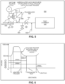
- a test system 500 in accordance with the alternative embodiment of the present invention includes a vacuum source 510 and a test chamber 540 connected by a vacuum conduit 550.
- the vacuum regulator 530 is disposed in the vacuum conduit 550 between the vacuum source 510 and a first valve 501 in the vacuum conduit 550.
- a second valve 502 is placed in the vacuum conduit 550 between the first valve 501 and the test chamber 540.
- a pressure transducer 520 is placed in communication with the vacuum conduit between the first valve 501 and the second valve 502.
- a third valve 503 for venting test system 500 is placed in communication with the vacuum conduit 550 between the first valve 501 and the second valve 502.
- a fourth valve 504 is introduced to bypass the vacuum regulator 530 for enhanced vacuum flow.
- a bypass conduit 560 is provided to bypass the vacuum regulator 510 and the first valve 501 by connecting the vacuum source 510 from point A of the vacuum conduit 550 to point B of the vacuum conduit 550 without passing through the vacuum regulator 530 and the first valve 501.
- a fourth valve 504 is placed in the bypass conduit 560 for controlling the bypass vacuum supply from point A to point B. Accordingly, the bypass conduit 560 provides an unregulated vacuum supply from point A to point B when the fourth valve 504 is open.
- a microcomputer including a timer provides control signals to the vacuum source 510, the vacuum regulator 530, the first valve 501, the second valve 502, the third valve 503, and the fourth valve 504, and receives a pressure signal from the pressure transducer 520 indicating pressure conditions in the test chamber 540.
- test system 500 With reference to FIGS. 5 and 6 , an example operation of the test system 500 is described.
- the test system is at a controlled vacuum of 500mbar, the first valve 501 and the fourth 504 are open, and the second valve 502 and third valve 503 are closed.
- the second valve 502 is opened and a vacuum begins to be drawn on the test chamber 540 by vacuum source 510.
- a regulated vacuum is drawn through the first valve 501 via vacuum regulator 530, and an unregulated vacuum is drawn through the fourth valve 504.
- the vacuum reading remains stable between a target vacuum level and atmospheric pressure.
- the test system 500 As the vacuum level is being drawn on the test chamber 540, the test system 500 is initially removing air volume and not building a vacuum level, and the vacuum remains at a vacuum plateau until air is evacuated. Once the air volume has generally been evacuated, the vacuum level builds quickly. As the test system 500 approaches the target vacuum level, a specific pressure threshold designated a vacuum trigger is detected by the pressure transducer 520 at time T2, at which point a delay timer is initiated in the control computer and the fourth valve 504 offering the unregulated vacuum is closed. For example and without limitation, in this example the trigger pressure is 700 mbar and the timer is set to 1 second.
- the first valve 501 offering regulated vacuum remains open, and the timer will determine the first valve 501 is closed at time T3 to isolate the vacuum source 510 from the test chamber 540, and thereby stop pulling vacuum on the chamber.
- the pressure transducer 520 then monitors the pressure in the test system to determine the existence of a leak in the package under test.
- the third valve 501 is opened to vent the test system 500.
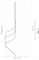
- the vacuum level in the test chamber will pass the trigger point, and upon the timer stopping the evacuation of the test chamber, a large leak in the package-under-test will cause a spike in pressure ( FIG. 7 , correct positive).
- the method reliably draws vacuum on pouches regardless of the time it takes to evacuate the general volume of the test chamber. A package that may be non-leaking but requires more time for the test chamber to be evacuated would not be detected as a leak ( FIG. 7 , correct negative).
- a flow diagram is depicted to illustrate a dynamic vacuum decay leak detection method consistent with the present invention.
- a controlled vacuum level is established in the test system at step 810, prior to communicating the test system to the test chamber.
- the first valve to selectively isolate the vacuum source is open, and the second valve to selectively isolate the test chamber from the test system is closed, such that the test chamber is isolated from the test system.
- the second valve is opened such that the vacuum source of the test system is in communication with the test chamber, and the test system begins to pull vacuum on the test chamber.
- a predetermined vacuum trigger is detected as vacuum in the test chamber begins to build, measured by the pressure transducer, and the detection of this vacuum trigger is fed back to a control system. Based on the detected vacuum trigger, the control system initiates the timer.
- the timer may be set to expire after 1 second.
- the first valve is closed to isolate the vacuum source from the test chamber.
- pressure between the test system and the test chamber is equalized, and pressure in the test system is monitored by the pressure transducer to determine the presence of a leak in the package under test.
- the third valve is opened to vent the test system.
- the present invention allows for a variety of package shapes and sizes to be placed into the test chamber with the same test parameters, and regardless of test chamber volume surrounding the package, it can provide an accurate vacuum evacuation. In doing so, large leaks can be detected on packages with low headspace and little volume surrounding the package. Simultaneously, a larger package format may be tested that requires a longer time to evacuate, and the system would dynamically be able to reach the appropriate vacuum level.
- Embodiments of the present invention are directed to a vacuum leak test operated using a vacuum decay control system and a test chamber.
- the leak test method may be deployed by a test controller system.
- the test controller can operate with a rigid test chamber or a flexible test chamber, although the use of a flexible test chamber is advantageous.
- the target vacuum level, the trigger vacuum level, and the timers associated with the test may vary, but generally would not need modification due to the intelligent dynamic vacuum system.
- Embodiments of the leak test method consistent with the present invention may be deployed in conjunction with other vacuum test solutions.
- the present invention offers distinct advantages to the vacuum decay leak detection of a wide variety of containers, and more particularly to the testing of containers filled with either dry product or liquid product such as non-porous vials, ampoules, injection cartridges, ophthalmic product packages, syringes, pouches, blister packages and other packages containing critical medicinal and/or chemical products.
- the use of the intelligent dynamic vacuum leak detection method of the present invention applies to the testing of containers using a method of dynamically controlling and measuring vacuum decay within a test chamber in which a container being tested is sealed and wherein as a vacuum is being pulled with the test chamber the pressure levels are continuously monitored, such that pressure conditions within the test chamber over a period of time are used to indicate passage or failure of a container being tested.
Landscapes
- Physics & Mathematics (AREA)
- General Physics & Mathematics (AREA)
- Examining Or Testing Airtightness (AREA)
Applications Claiming Priority (2)
| Application Number | Priority Date | Filing Date | Title |
|---|---|---|---|
| US201662439279P | 2016-12-27 | 2016-12-27 | |
| PCT/US2017/068608 WO2018125946A1 (en) | 2016-12-27 | 2017-12-27 | Dynamic vacuum decay leak detection method and apparatus |
Publications (4)
| Publication Number | Publication Date |
|---|---|
| EP3563133A1 EP3563133A1 (en) | 2019-11-06 |
| EP3563133A4 EP3563133A4 (en) | 2020-08-12 |
| EP3563133B1 true EP3563133B1 (en) | 2024-10-23 |
| EP3563133C0 EP3563133C0 (en) | 2024-10-23 |
Family
ID=62709879
Family Applications (1)
| Application Number | Title | Priority Date | Filing Date |
|---|---|---|---|
| EP17886414.6A Active EP3563133B1 (en) | 2016-12-27 | 2017-12-27 | Dynamic vacuum decay leak detection method and apparatus |
Country Status (7)
| Country | Link |
|---|---|
| US (1) | US11067472B2 (cg-RX-API-DMAC7.html) |
| EP (1) | EP3563133B1 (cg-RX-API-DMAC7.html) |
| JP (1) | JP7008986B2 (cg-RX-API-DMAC7.html) |
| KR (1) | KR102574722B1 (cg-RX-API-DMAC7.html) |
| ES (1) | ES2993936T3 (cg-RX-API-DMAC7.html) |
| PL (1) | PL3563133T3 (cg-RX-API-DMAC7.html) |
| WO (1) | WO2018125946A1 (cg-RX-API-DMAC7.html) |
Families Citing this family (7)
| Publication number | Priority date | Publication date | Assignee | Title |
|---|---|---|---|---|
| KR102482175B1 (ko) * | 2017-06-21 | 2022-12-29 | 삼성전자 주식회사 | 통기 검사 장치 및 방법 |
| CN107702870B (zh) * | 2017-11-07 | 2019-12-17 | 苏州富强科技有限公司 | 一种密封结构的密封性检测方法 |
| ES2963894T3 (es) * | 2018-08-10 | 2024-04-03 | Packaging Tech & Inspection Llc | Detección de fugas por caída de vacío con corrección para interferencias |
| US12259301B2 (en) * | 2021-03-31 | 2025-03-25 | Packaging Technologies & Inspection, LLC | System and method for dynamic signal processing for vacuum decay leak detection |
| GB2609962A (en) * | 2021-08-19 | 2023-02-22 | Atlas Copco Airpower Nv | Leak detection of vacuum systems |
| CN114289344B (zh) * | 2021-12-31 | 2023-06-23 | 山东新华医疗器械股份有限公司 | 一种联动生产型真空衰减检漏机 |
| CN115655605A (zh) * | 2022-10-19 | 2023-01-31 | 中广核工程有限公司 | 真空检漏系统及方法 |
Family Cites Families (48)
| Publication number | Priority date | Publication date | Assignee | Title |
|---|---|---|---|---|
| US2784373A (en) * | 1953-03-02 | 1957-03-05 | Nat Res Corp | High-vacuum device |
| US2855777A (en) * | 1956-02-03 | 1958-10-14 | Moore Products Co | Vacuum leak testing apparatus |
| US3800586A (en) * | 1972-04-24 | 1974-04-02 | Uson Corp | Leak testing apparatus |
| DE2928336B1 (de) * | 1979-07-13 | 1980-12-18 | Pfeiffer Vakuumtechnik | Leckraten-Messeinrichtung |
| US4272985A (en) * | 1979-12-03 | 1981-06-16 | Uson Corporation | Method of and apparatus for compensating for temperature in leak testing |
| US4409817A (en) * | 1981-03-25 | 1983-10-18 | Edwards Jr David | Vacuum leak detector and method |
| JPS5834337A (ja) * | 1981-08-25 | 1983-02-28 | Dainippon Printing Co Ltd | 容器の漏れ検査装置 |
| US4587619A (en) * | 1981-12-14 | 1986-05-06 | Scans Associates, Inc. | Method and apparatus for electronic leak testing |
| US4831870A (en) * | 1987-10-21 | 1989-05-23 | The Viking Corporation | Method and apparatus for vacuum testing glass bulbs for sprinklers |
| EP0432143B1 (de) * | 1987-10-28 | 1994-06-08 | Martin Lehmann | Verfahren und Verwendung einer Anordnung zur Prüfung mindestens eines Hohlkörpers auf sein Volumenverhalten |
| US5170660A (en) * | 1987-10-28 | 1992-12-15 | Martin Lehmann | Process and apparatus for volume-testing a hollow body |
| US5199296A (en) * | 1989-01-27 | 1993-04-06 | Martin Lehmann | Method for reducing test cycle time and for improving measuring accuracy at a leak testing process |
| US4899574A (en) | 1989-02-01 | 1990-02-13 | The Mead Corporation | Method and apparatus for detecting leaks in a sealed container |
| US5235845A (en) * | 1990-02-06 | 1993-08-17 | Sumitomo Metal Mining Co., Ltd. | Method of detecting a pinhole at a welded portion of an article |
| US5111684A (en) | 1990-11-21 | 1992-05-12 | Pack Systems | Method and apparatus for leak testing packages |
| US5513516A (en) * | 1992-05-01 | 1996-05-07 | Visi-Pack, Inc. | Method and apparatus for leak testing a container |
| US6662634B2 (en) * | 1994-06-15 | 2003-12-16 | Martin Lehmann | Method for testing containers, use of the method, and a testing device |
| EP0791814A3 (en) * | 1997-05-26 | 1997-11-26 | Martin Lehmann | Method for leak testing and leak testing apparatus |
| US6082184A (en) * | 1997-05-27 | 2000-07-04 | Martin Lehmann | Method for leak testing and leak testing apparatus |
| US5847264A (en) * | 1997-03-31 | 1998-12-08 | Roper Holdings, Inc. | Leak tester with flexible equation capabilities |
| JPH11304633A (ja) * | 1998-04-21 | 1999-11-05 | Matsushita Electric Works Ltd | エアーリーク検出装置 |
| US6003363A (en) * | 1998-09-18 | 1999-12-21 | Fastest, Inc. | Leak detection apparatus and method |
| JP2000203539A (ja) | 1999-01-06 | 2000-07-25 | Oita Kikai Kogyo Kk | 紙パック容器の検査方法及びその検査装置 |
| US6286362B1 (en) * | 1999-03-31 | 2001-09-11 | Applied Materials, Inc. | Dual mode leak detector |
| US6530265B2 (en) * | 1999-08-30 | 2003-03-11 | Daimlerchrysler Corporation | Small/gross leak check |
| US6526809B2 (en) * | 2000-03-30 | 2003-03-04 | Cincinnati Test Systems, Inc. | Method for identifying leaks in a sealed package having a liquid therein |
| US6513366B1 (en) * | 2001-10-11 | 2003-02-04 | Packaging Technologies & Inspection Llc | Method and apparatus for package leak testing |
| JP3820168B2 (ja) * | 2002-03-15 | 2006-09-13 | オリンパス株式会社 | リークテスタ |
| US6834534B2 (en) * | 2003-03-17 | 2004-12-28 | Veeder-Root Company | Fuel storage tank leak prevention and detection system and method |
| US7334456B2 (en) * | 2004-05-11 | 2008-02-26 | Franklin Fueling Systems, Inc. | Method and apparatus for continuously monitoring interstitial regions in gasoline storage facilities and pipelines |
| CA2569700A1 (en) * | 2004-06-07 | 2005-12-22 | Inspection Machinery (No 2) Pty Ltd | An apparatus and method for testing flexible packages for defects |
| US7380440B2 (en) * | 2005-09-09 | 2008-06-03 | Martin Lehmann | Methods for manufacturing unleaky closed containers and leak testing apparatus |
| MX2008014076A (es) * | 2006-05-24 | 2009-02-10 | Cosmo Instr Co Ltd | Metodo de inspeccion de fuga e inspector de fuga. |
| US20080081000A1 (en) * | 2006-09-29 | 2008-04-03 | Macleod John | Integrity testing of vials for test sensors |
| US7788967B2 (en) * | 2007-05-02 | 2010-09-07 | Praxair Technology, Inc. | Method and apparatus for leak detection |
| US20110100095A1 (en) * | 2009-07-01 | 2011-05-05 | Los Alamos National Security, Llc | Passive Glovebox Glove Leak Detector |
| US20110000282A1 (en) * | 2009-07-01 | 2011-01-06 | Los Alamos National Security, Llc | Passive glovebox glove leak detector |
| ES2665764T3 (es) | 2009-11-20 | 2018-04-27 | Packaging Technologies & Inspection Llc | Estado de vacío en reposo para procedimiento y sistema de prueba de estanqueidad mediante medida de disminución del vacío |
| JP2011191203A (ja) | 2010-03-15 | 2011-09-29 | Toyo Seikan Kaisha Ltd | 容器の気密性検査方法及び検査システム |
| US8692186B2 (en) * | 2010-08-10 | 2014-04-08 | Wilco Ag | Method and apparatus for leak testing containers |
| US20120291457A1 (en) * | 2011-05-17 | 2012-11-22 | Service Solutions U.S. Llc | Pressure Decay Leak Check Method and Apparatus |
| US9038440B2 (en) * | 2012-05-01 | 2015-05-26 | Audyssey Laboratories, Inc. | Speaker leak test system and method |
| CN105358951B (zh) * | 2013-05-07 | 2019-06-28 | 吕多尔管理有限公司 | 密封性检验装置和密封性检验方法 |
| US10646732B2 (en) * | 2014-12-12 | 2020-05-12 | Honeywell International Inc. | Testing a mask seal |
| US10161824B2 (en) * | 2015-05-11 | 2018-12-25 | HilFlo, LLC | Hydrostatic pressure test method and apparatus |
| US10401255B1 (en) * | 2015-12-16 | 2019-09-03 | LACO Technologies, Inc. | Vacuum leak testing |
| JP6536476B2 (ja) * | 2016-05-13 | 2019-07-03 | 株式会社デンソー | エバポリークチェックシステム、および、これを用いたエバポリークのチェック方法 |
| DE102017204102A1 (de) * | 2017-03-13 | 2018-09-13 | Robert Bosch Gmbh | Verfahren zum Prüfen eines Behälters auf Dichtheit |
-
2017
- 2017-12-27 JP JP2019534748A patent/JP7008986B2/ja active Active
- 2017-12-27 KR KR1020197021590A patent/KR102574722B1/ko active Active
- 2017-12-27 US US16/474,466 patent/US11067472B2/en active Active
- 2017-12-27 EP EP17886414.6A patent/EP3563133B1/en active Active
- 2017-12-27 PL PL17886414.6T patent/PL3563133T3/pl unknown
- 2017-12-27 ES ES17886414T patent/ES2993936T3/es active Active
- 2017-12-27 WO PCT/US2017/068608 patent/WO2018125946A1/en not_active Ceased
Also Published As
| Publication number | Publication date |
|---|---|
| ES2993936T3 (en) | 2025-01-14 |
| KR20190102222A (ko) | 2019-09-03 |
| EP3563133A4 (en) | 2020-08-12 |
| PL3563133T3 (pl) | 2025-02-24 |
| US11067472B2 (en) | 2021-07-20 |
| WO2018125946A1 (en) | 2018-07-05 |
| EP3563133A1 (en) | 2019-11-06 |
| EP3563133C0 (en) | 2024-10-23 |
| KR102574722B1 (ko) | 2023-09-07 |
| US20190339157A1 (en) | 2019-11-07 |
| JP2020503513A (ja) | 2020-01-30 |
| JP7008986B2 (ja) | 2022-01-25 |
Similar Documents
| Publication | Publication Date | Title |
|---|---|---|
| EP3563133B1 (en) | Dynamic vacuum decay leak detection method and apparatus | |
| EP2502043B1 (en) | At rest vacuum state for vacuum decay leak testing method and system | |
| JP2854534B2 (ja) | 中空体の試験方法及び装置 | |
| EP3757538B1 (en) | System and method for detecting a possible loss of integrity of a flexible bag for biopharmaceutical product | |
| JP6791944B2 (ja) | 密封製品の耐漏洩性を制御する方法及び漏洩検出装置 | |
| EP1836467B1 (en) | Instrument and method for detecting leaks in hermetically sealed packaging | |
| US11105704B2 (en) | Method and apparatus for an integrity test of a flexible container with inspection fluid | |
| US11846566B2 (en) | System and method for detecting a possible loss of integrity of a flexible bag for biopharmaceutical product | |
| US10900862B2 (en) | Gross leak measurement in an incompressible test item in a film chamber | |
| CN107076636A (zh) | 具有用于粗泄漏测试的测量体积的薄膜腔 | |
| JP2020503513A5 (cg-RX-API-DMAC7.html) | ||
| CN104614136A (zh) | 一种真空衰减法测试卷烟包装体泄漏测试方法 | |
| US9733147B2 (en) | Method for testing a leakage detection system | |
| US10545068B2 (en) | Arrangement and method for testing the tightness of a container | |
| JP2003294570A (ja) | エアリーク測定装置 | |
| US20230408365A1 (en) | System and Method for Leak Testing a Sealed Package | |
| EP1469296A1 (en) | Process and apparatus for checking sealor tightness of a package made of flexible or semirigid material | |
| JP3108781B2 (ja) | 密閉合成樹脂製容器のリーク検査装置 |
Legal Events
| Date | Code | Title | Description |
|---|---|---|---|
| STAA | Information on the status of an ep patent application or granted ep patent |
Free format text: STATUS: THE INTERNATIONAL PUBLICATION HAS BEEN MADE |
|
| PUAI | Public reference made under article 153(3) epc to a published international application that has entered the european phase |
Free format text: ORIGINAL CODE: 0009012 |
|
| STAA | Information on the status of an ep patent application or granted ep patent |
Free format text: STATUS: REQUEST FOR EXAMINATION WAS MADE |
|
| 17P | Request for examination filed |
Effective date: 20190719 |
|
| AK | Designated contracting states |
Kind code of ref document: A1 Designated state(s): AL AT BE BG CH CY CZ DE DK EE ES FI FR GB GR HR HU IE IS IT LI LT LU LV MC MK MT NL NO PL PT RO RS SE SI SK SM TR |
|
| AX | Request for extension of the european patent |
Extension state: BA ME |
|
| DAV | Request for validation of the european patent (deleted) | ||
| DAX | Request for extension of the european patent (deleted) | ||
| A4 | Supplementary search report drawn up and despatched |
Effective date: 20200709 |
|
| RIC1 | Information provided on ipc code assigned before grant |
Ipc: G01M 3/20 20060101ALI20200704BHEP Ipc: G01M 3/36 20060101AFI20200704BHEP Ipc: G01M 3/34 20060101ALI20200704BHEP Ipc: G01M 3/32 20060101ALI20200704BHEP |
|
| STAA | Information on the status of an ep patent application or granted ep patent |
Free format text: STATUS: EXAMINATION IS IN PROGRESS |
|
| 17Q | First examination report despatched |
Effective date: 20220914 |
|
| GRAP | Despatch of communication of intention to grant a patent |
Free format text: ORIGINAL CODE: EPIDOSNIGR1 |
|
| STAA | Information on the status of an ep patent application or granted ep patent |
Free format text: STATUS: GRANT OF PATENT IS INTENDED |
|
| INTG | Intention to grant announced |
Effective date: 20240517 |
|
| GRAS | Grant fee paid |
Free format text: ORIGINAL CODE: EPIDOSNIGR3 |
|
| GRAA | (expected) grant |
Free format text: ORIGINAL CODE: 0009210 |
|
| STAA | Information on the status of an ep patent application or granted ep patent |
Free format text: STATUS: THE PATENT HAS BEEN GRANTED |
|
| AK | Designated contracting states |
Kind code of ref document: B1 Designated state(s): AL AT BE BG CH CY CZ DE DK EE ES FI FR GB GR HR HU IE IS IT LI LT LU LV MC MK MT NL NO PL PT RO RS SE SI SK SM TR |
|
| RAP3 | Party data changed (applicant data changed or rights of an application transferred) |
Owner name: PACKAGING TECHNOLOGIES & INSPECTION LLC |
|
| REG | Reference to a national code |
Ref country code: GB Ref legal event code: FG4D |
|
| RIN1 | Information on inventor provided before grant (corrected) |
Inventor name: STAUFFER, ANTON Inventor name: STAUFFER, OLIVER |
|
| REG | Reference to a national code |
Ref country code: CH Ref legal event code: EP |
|
| REG | Reference to a national code |
Ref country code: DE Ref legal event code: R096 Ref document number: 602017085707 Country of ref document: DE |
|
| REG | Reference to a national code |
Ref country code: IE Ref legal event code: FG4D |
|
| U01 | Request for unitary effect filed |
Effective date: 20241106 |
|
| U07 | Unitary effect registered |
Designated state(s): AT BE BG DE DK EE FI FR IT LT LU LV MT NL PT RO SE SI Effective date: 20241114 |
|
| REG | Reference to a national code |
Ref country code: ES Ref legal event code: FG2A Ref document number: 2993936 Country of ref document: ES Kind code of ref document: T3 Effective date: 20250114 |
|
| PGFP | Annual fee paid to national office [announced via postgrant information from national office to epo] |
Ref country code: GB Payment date: 20241215 Year of fee payment: 8 |
|
| U20 | Renewal fee for the european patent with unitary effect paid |
Year of fee payment: 8 Effective date: 20241219 |
|
| PG25 | Lapsed in a contracting state [announced via postgrant information from national office to epo] |
Ref country code: IS Free format text: LAPSE BECAUSE OF FAILURE TO SUBMIT A TRANSLATION OF THE DESCRIPTION OR TO PAY THE FEE WITHIN THE PRESCRIBED TIME-LIMIT Effective date: 20250223 Ref country code: HR Free format text: LAPSE BECAUSE OF FAILURE TO SUBMIT A TRANSLATION OF THE DESCRIPTION OR TO PAY THE FEE WITHIN THE PRESCRIBED TIME-LIMIT Effective date: 20241023 |
|
| PGFP | Annual fee paid to national office [announced via postgrant information from national office to epo] |
Ref country code: ES Payment date: 20250102 Year of fee payment: 8 |
|
| PG25 | Lapsed in a contracting state [announced via postgrant information from national office to epo] |
Ref country code: NO Free format text: LAPSE BECAUSE OF FAILURE TO SUBMIT A TRANSLATION OF THE DESCRIPTION OR TO PAY THE FEE WITHIN THE PRESCRIBED TIME-LIMIT Effective date: 20250123 |
|
| PG25 | Lapsed in a contracting state [announced via postgrant information from national office to epo] |
Ref country code: GR Free format text: LAPSE BECAUSE OF FAILURE TO SUBMIT A TRANSLATION OF THE DESCRIPTION OR TO PAY THE FEE WITHIN THE PRESCRIBED TIME-LIMIT Effective date: 20250124 |
|
| PGFP | Annual fee paid to national office [announced via postgrant information from national office to epo] |
Ref country code: CH Payment date: 20250101 Year of fee payment: 8 |
|
| PGFP | Annual fee paid to national office [announced via postgrant information from national office to epo] |
Ref country code: PL Payment date: 20250115 Year of fee payment: 8 |
|
| PG25 | Lapsed in a contracting state [announced via postgrant information from national office to epo] |
Ref country code: RS Free format text: LAPSE BECAUSE OF FAILURE TO SUBMIT A TRANSLATION OF THE DESCRIPTION OR TO PAY THE FEE WITHIN THE PRESCRIBED TIME-LIMIT Effective date: 20250123 |
|
| PG25 | Lapsed in a contracting state [announced via postgrant information from national office to epo] |
Ref country code: SM Free format text: LAPSE BECAUSE OF FAILURE TO SUBMIT A TRANSLATION OF THE DESCRIPTION OR TO PAY THE FEE WITHIN THE PRESCRIBED TIME-LIMIT Effective date: 20241023 |
|
| PG25 | Lapsed in a contracting state [announced via postgrant information from national office to epo] |
Ref country code: MC Free format text: LAPSE BECAUSE OF FAILURE TO SUBMIT A TRANSLATION OF THE DESCRIPTION OR TO PAY THE FEE WITHIN THE PRESCRIBED TIME-LIMIT Effective date: 20241023 |
|
| PG25 | Lapsed in a contracting state [announced via postgrant information from national office to epo] |
Ref country code: SK Free format text: LAPSE BECAUSE OF FAILURE TO SUBMIT A TRANSLATION OF THE DESCRIPTION OR TO PAY THE FEE WITHIN THE PRESCRIBED TIME-LIMIT Effective date: 20241023 |
|
| PG25 | Lapsed in a contracting state [announced via postgrant information from national office to epo] |
Ref country code: CZ Free format text: LAPSE BECAUSE OF FAILURE TO SUBMIT A TRANSLATION OF THE DESCRIPTION OR TO PAY THE FEE WITHIN THE PRESCRIBED TIME-LIMIT Effective date: 20241023 |
|
| PLBE | No opposition filed within time limit |
Free format text: ORIGINAL CODE: 0009261 |
|
| STAA | Information on the status of an ep patent application or granted ep patent |
Free format text: STATUS: NO OPPOSITION FILED WITHIN TIME LIMIT |
|
| 26N | No opposition filed |
Effective date: 20250724 |
|
| PG25 | Lapsed in a contracting state [announced via postgrant information from national office to epo] |
Ref country code: IE Free format text: LAPSE BECAUSE OF NON-PAYMENT OF DUE FEES Effective date: 20241227 |