EP3561284A2 - Abgasrückführungsanordnung mit wärmetauscher, wärmetauscher und brennkraftmaschine - Google Patents
Abgasrückführungsanordnung mit wärmetauscher, wärmetauscher und brennkraftmaschine Download PDFInfo
- Publication number
- EP3561284A2 EP3561284A2 EP19170265.3A EP19170265A EP3561284A2 EP 3561284 A2 EP3561284 A2 EP 3561284A2 EP 19170265 A EP19170265 A EP 19170265A EP 3561284 A2 EP3561284 A2 EP 3561284A2
- Authority
- EP
- European Patent Office
- Prior art keywords
- exhaust gas
- gas recirculation
- fluid
- heat exchanger
- arrangement
- Prior art date
- Legal status (The legal status is an assumption and is not a legal conclusion. Google has not performed a legal analysis and makes no representation as to the accuracy of the status listed.)
- Granted
Links
Images

Classifications
-
- F—MECHANICAL ENGINEERING; LIGHTING; HEATING; WEAPONS; BLASTING
- F01—MACHINES OR ENGINES IN GENERAL; ENGINE PLANTS IN GENERAL; STEAM ENGINES
- F01N—GAS-FLOW SILENCERS OR EXHAUST APPARATUS FOR MACHINES OR ENGINES IN GENERAL; GAS-FLOW SILENCERS OR EXHAUST APPARATUS FOR INTERNAL-COMBUSTION ENGINES
- F01N3/00—Exhaust or silencing apparatus having means for purifying, rendering innocuous, or otherwise treating exhaust
- F01N3/02—Exhaust or silencing apparatus having means for purifying, rendering innocuous, or otherwise treating exhaust for cooling, or for removing solid constituents of, exhaust
- F01N3/0205—Exhaust or silencing apparatus having means for purifying, rendering innocuous, or otherwise treating exhaust for cooling, or for removing solid constituents of, exhaust using heat exchangers
-
- F—MECHANICAL ENGINEERING; LIGHTING; HEATING; WEAPONS; BLASTING
- F02—COMBUSTION ENGINES; HOT-GAS OR COMBUSTION-PRODUCT ENGINE PLANTS
- F02M—SUPPLYING COMBUSTION ENGINES IN GENERAL WITH COMBUSTIBLE MIXTURES OR CONSTITUENTS THEREOF
- F02M26/00—Engine-pertinent apparatus for adding exhaust gases to combustion-air, main fuel or fuel-air mixture, e.g. by exhaust gas recirculation [EGR] systems
- F02M26/02—EGR systems specially adapted for supercharged engines
- F02M26/04—EGR systems specially adapted for supercharged engines with a single turbocharger
- F02M26/06—Low pressure loops, i.e. wherein recirculated exhaust gas is taken out from the exhaust downstream of the turbocharger turbine and reintroduced into the intake system upstream of the compressor
-
- F—MECHANICAL ENGINEERING; LIGHTING; HEATING; WEAPONS; BLASTING
- F02—COMBUSTION ENGINES; HOT-GAS OR COMBUSTION-PRODUCT ENGINE PLANTS
- F02M—SUPPLYING COMBUSTION ENGINES IN GENERAL WITH COMBUSTIBLE MIXTURES OR CONSTITUENTS THEREOF
- F02M26/00—Engine-pertinent apparatus for adding exhaust gases to combustion-air, main fuel or fuel-air mixture, e.g. by exhaust gas recirculation [EGR] systems
- F02M26/13—Arrangement or layout of EGR passages, e.g. in relation to specific engine parts or for incorporation of accessories
- F02M26/22—Arrangement or layout of EGR passages, e.g. in relation to specific engine parts or for incorporation of accessories with coolers in the recirculation passage
-
- F—MECHANICAL ENGINEERING; LIGHTING; HEATING; WEAPONS; BLASTING
- F02—COMBUSTION ENGINES; HOT-GAS OR COMBUSTION-PRODUCT ENGINE PLANTS
- F02M—SUPPLYING COMBUSTION ENGINES IN GENERAL WITH COMBUSTIBLE MIXTURES OR CONSTITUENTS THEREOF
- F02M26/00—Engine-pertinent apparatus for adding exhaust gases to combustion-air, main fuel or fuel-air mixture, e.g. by exhaust gas recirculation [EGR] systems
- F02M26/13—Arrangement or layout of EGR passages, e.g. in relation to specific engine parts or for incorporation of accessories
- F02M26/22—Arrangement or layout of EGR passages, e.g. in relation to specific engine parts or for incorporation of accessories with coolers in the recirculation passage
- F02M26/23—Layout, e.g. schematics
- F02M26/24—Layout, e.g. schematics with two or more coolers
-
- F—MECHANICAL ENGINEERING; LIGHTING; HEATING; WEAPONS; BLASTING
- F02—COMBUSTION ENGINES; HOT-GAS OR COMBUSTION-PRODUCT ENGINE PLANTS
- F02M—SUPPLYING COMBUSTION ENGINES IN GENERAL WITH COMBUSTIBLE MIXTURES OR CONSTITUENTS THEREOF
- F02M26/00—Engine-pertinent apparatus for adding exhaust gases to combustion-air, main fuel or fuel-air mixture, e.g. by exhaust gas recirculation [EGR] systems
- F02M26/13—Arrangement or layout of EGR passages, e.g. in relation to specific engine parts or for incorporation of accessories
- F02M26/22—Arrangement or layout of EGR passages, e.g. in relation to specific engine parts or for incorporation of accessories with coolers in the recirculation passage
- F02M26/23—Layout, e.g. schematics
- F02M26/28—Layout, e.g. schematics with liquid-cooled heat exchangers
-
- F—MECHANICAL ENGINEERING; LIGHTING; HEATING; WEAPONS; BLASTING
- F02—COMBUSTION ENGINES; HOT-GAS OR COMBUSTION-PRODUCT ENGINE PLANTS
- F02M—SUPPLYING COMBUSTION ENGINES IN GENERAL WITH COMBUSTIBLE MIXTURES OR CONSTITUENTS THEREOF
- F02M26/00—Engine-pertinent apparatus for adding exhaust gases to combustion-air, main fuel or fuel-air mixture, e.g. by exhaust gas recirculation [EGR] systems
- F02M26/13—Arrangement or layout of EGR passages, e.g. in relation to specific engine parts or for incorporation of accessories
- F02M26/22—Arrangement or layout of EGR passages, e.g. in relation to specific engine parts or for incorporation of accessories with coolers in the recirculation passage
- F02M26/29—Constructional details of the coolers, e.g. pipes, plates, ribs, insulation or materials
- F02M26/32—Liquid-cooled heat exchangers
-
- F—MECHANICAL ENGINEERING; LIGHTING; HEATING; WEAPONS; BLASTING
- F02—COMBUSTION ENGINES; HOT-GAS OR COMBUSTION-PRODUCT ENGINE PLANTS
- F02M—SUPPLYING COMBUSTION ENGINES IN GENERAL WITH COMBUSTIBLE MIXTURES OR CONSTITUENTS THEREOF
- F02M26/00—Engine-pertinent apparatus for adding exhaust gases to combustion-air, main fuel or fuel-air mixture, e.g. by exhaust gas recirculation [EGR] systems
- F02M26/13—Arrangement or layout of EGR passages, e.g. in relation to specific engine parts or for incorporation of accessories
- F02M26/22—Arrangement or layout of EGR passages, e.g. in relation to specific engine parts or for incorporation of accessories with coolers in the recirculation passage
- F02M26/33—Arrangement or layout of EGR passages, e.g. in relation to specific engine parts or for incorporation of accessories with coolers in the recirculation passage controlling the temperature of the recirculated gases
-
- F—MECHANICAL ENGINEERING; LIGHTING; HEATING; WEAPONS; BLASTING
- F28—HEAT EXCHANGE IN GENERAL
- F28D—HEAT-EXCHANGE APPARATUS, NOT PROVIDED FOR IN ANOTHER SUBCLASS, IN WHICH THE HEAT-EXCHANGE MEDIA DO NOT COME INTO DIRECT CONTACT
- F28D7/00—Heat-exchange apparatus having stationary tubular conduit assemblies for both heat-exchange media, the media being in contact with different sides of a conduit wall
- F28D7/10—Heat-exchange apparatus having stationary tubular conduit assemblies for both heat-exchange media, the media being in contact with different sides of a conduit wall the conduits being arranged one within the other, e.g. concentrically
-
- F—MECHANICAL ENGINEERING; LIGHTING; HEATING; WEAPONS; BLASTING
- F28—HEAT EXCHANGE IN GENERAL
- F28D—HEAT-EXCHANGE APPARATUS, NOT PROVIDED FOR IN ANOTHER SUBCLASS, IN WHICH THE HEAT-EXCHANGE MEDIA DO NOT COME INTO DIRECT CONTACT
- F28D7/00—Heat-exchange apparatus having stationary tubular conduit assemblies for both heat-exchange media, the media being in contact with different sides of a conduit wall
- F28D7/10—Heat-exchange apparatus having stationary tubular conduit assemblies for both heat-exchange media, the media being in contact with different sides of a conduit wall the conduits being arranged one within the other, e.g. concentrically
- F28D7/103—Heat-exchange apparatus having stationary tubular conduit assemblies for both heat-exchange media, the media being in contact with different sides of a conduit wall the conduits being arranged one within the other, e.g. concentrically consisting of more than two coaxial conduits or modules of more than two coaxial conduits
-
- F—MECHANICAL ENGINEERING; LIGHTING; HEATING; WEAPONS; BLASTING
- F28—HEAT EXCHANGE IN GENERAL
- F28D—HEAT-EXCHANGE APPARATUS, NOT PROVIDED FOR IN ANOTHER SUBCLASS, IN WHICH THE HEAT-EXCHANGE MEDIA DO NOT COME INTO DIRECT CONTACT
- F28D7/00—Heat-exchange apparatus having stationary tubular conduit assemblies for both heat-exchange media, the media being in contact with different sides of a conduit wall
- F28D7/10—Heat-exchange apparatus having stationary tubular conduit assemblies for both heat-exchange media, the media being in contact with different sides of a conduit wall the conduits being arranged one within the other, e.g. concentrically
- F28D7/12—Heat-exchange apparatus having stationary tubular conduit assemblies for both heat-exchange media, the media being in contact with different sides of a conduit wall the conduits being arranged one within the other, e.g. concentrically the surrounding tube being closed at one end, e.g. return type
-
- F—MECHANICAL ENGINEERING; LIGHTING; HEATING; WEAPONS; BLASTING
- F01—MACHINES OR ENGINES IN GENERAL; ENGINE PLANTS IN GENERAL; STEAM ENGINES
- F01N—GAS-FLOW SILENCERS OR EXHAUST APPARATUS FOR MACHINES OR ENGINES IN GENERAL; GAS-FLOW SILENCERS OR EXHAUST APPARATUS FOR INTERNAL-COMBUSTION ENGINES
- F01N13/00—Exhaust or silencing apparatus characterised by constructional features
- F01N13/009—Exhaust or silencing apparatus characterised by constructional features having two or more separate purifying devices arranged in series
-
- F—MECHANICAL ENGINEERING; LIGHTING; HEATING; WEAPONS; BLASTING
- F01—MACHINES OR ENGINES IN GENERAL; ENGINE PLANTS IN GENERAL; STEAM ENGINES
- F01N—GAS-FLOW SILENCERS OR EXHAUST APPARATUS FOR MACHINES OR ENGINES IN GENERAL; GAS-FLOW SILENCERS OR EXHAUST APPARATUS FOR INTERNAL-COMBUSTION ENGINES
- F01N2240/00—Combination or association of two or more different exhaust treating devices, or of at least one such device with an auxiliary device, not covered by indexing codes F01N2230/00 or F01N2250/00, one of the devices being
- F01N2240/02—Combination or association of two or more different exhaust treating devices, or of at least one such device with an auxiliary device, not covered by indexing codes F01N2230/00 or F01N2250/00, one of the devices being a heat exchanger
-
- F—MECHANICAL ENGINEERING; LIGHTING; HEATING; WEAPONS; BLASTING
- F01—MACHINES OR ENGINES IN GENERAL; ENGINE PLANTS IN GENERAL; STEAM ENGINES
- F01N—GAS-FLOW SILENCERS OR EXHAUST APPARATUS FOR MACHINES OR ENGINES IN GENERAL; GAS-FLOW SILENCERS OR EXHAUST APPARATUS FOR INTERNAL-COMBUSTION ENGINES
- F01N2260/00—Exhaust treating devices having provisions not otherwise provided for
- F01N2260/08—Exhaust treating devices having provisions not otherwise provided for for preventing heat loss or temperature drop, using other means than layers of heat-insulating material
-
- F—MECHANICAL ENGINEERING; LIGHTING; HEATING; WEAPONS; BLASTING
- F01—MACHINES OR ENGINES IN GENERAL; ENGINE PLANTS IN GENERAL; STEAM ENGINES
- F01N—GAS-FLOW SILENCERS OR EXHAUST APPARATUS FOR MACHINES OR ENGINES IN GENERAL; GAS-FLOW SILENCERS OR EXHAUST APPARATUS FOR INTERNAL-COMBUSTION ENGINES
- F01N3/00—Exhaust or silencing apparatus having means for purifying, rendering innocuous, or otherwise treating exhaust
- F01N3/02—Exhaust or silencing apparatus having means for purifying, rendering innocuous, or otherwise treating exhaust for cooling, or for removing solid constituents of, exhaust
- F01N3/021—Exhaust or silencing apparatus having means for purifying, rendering innocuous, or otherwise treating exhaust for cooling, or for removing solid constituents of, exhaust by means of filters
-
- F—MECHANICAL ENGINEERING; LIGHTING; HEATING; WEAPONS; BLASTING
- F01—MACHINES OR ENGINES IN GENERAL; ENGINE PLANTS IN GENERAL; STEAM ENGINES
- F01N—GAS-FLOW SILENCERS OR EXHAUST APPARATUS FOR MACHINES OR ENGINES IN GENERAL; GAS-FLOW SILENCERS OR EXHAUST APPARATUS FOR INTERNAL-COMBUSTION ENGINES
- F01N3/00—Exhaust or silencing apparatus having means for purifying, rendering innocuous, or otherwise treating exhaust
- F01N3/08—Exhaust or silencing apparatus having means for purifying, rendering innocuous, or otherwise treating exhaust for rendering innocuous
- F01N3/10—Exhaust or silencing apparatus having means for purifying, rendering innocuous, or otherwise treating exhaust for rendering innocuous by thermal or catalytic conversion of noxious components of exhaust
-
- F—MECHANICAL ENGINEERING; LIGHTING; HEATING; WEAPONS; BLASTING
- F02—COMBUSTION ENGINES; HOT-GAS OR COMBUSTION-PRODUCT ENGINE PLANTS
- F02M—SUPPLYING COMBUSTION ENGINES IN GENERAL WITH COMBUSTIBLE MIXTURES OR CONSTITUENTS THEREOF
- F02M26/00—Engine-pertinent apparatus for adding exhaust gases to combustion-air, main fuel or fuel-air mixture, e.g. by exhaust gas recirculation [EGR] systems
- F02M26/02—EGR systems specially adapted for supercharged engines
- F02M26/09—Constructional details, e.g. structural combinations of EGR systems and supercharger systems; Arrangement of the EGR and supercharger systems with respect to the engine
- F02M26/10—Constructional details, e.g. structural combinations of EGR systems and supercharger systems; Arrangement of the EGR and supercharger systems with respect to the engine having means to increase the pressure difference between the exhaust and intake system, e.g. venturis, variable geometry turbines, check valves using pressure pulsations or throttles in the air intake or exhaust system
-
- F—MECHANICAL ENGINEERING; LIGHTING; HEATING; WEAPONS; BLASTING
- F02—COMBUSTION ENGINES; HOT-GAS OR COMBUSTION-PRODUCT ENGINE PLANTS
- F02M—SUPPLYING COMBUSTION ENGINES IN GENERAL WITH COMBUSTIBLE MIXTURES OR CONSTITUENTS THEREOF
- F02M26/00—Engine-pertinent apparatus for adding exhaust gases to combustion-air, main fuel or fuel-air mixture, e.g. by exhaust gas recirculation [EGR] systems
- F02M26/13—Arrangement or layout of EGR passages, e.g. in relation to specific engine parts or for incorporation of accessories
- F02M26/35—Arrangement or layout of EGR passages, e.g. in relation to specific engine parts or for incorporation of accessories with means for cleaning or treating the recirculated gases, e.g. catalysts, condensate traps, particle filters or heaters
-
- Y—GENERAL TAGGING OF NEW TECHNOLOGICAL DEVELOPMENTS; GENERAL TAGGING OF CROSS-SECTIONAL TECHNOLOGIES SPANNING OVER SEVERAL SECTIONS OF THE IPC; TECHNICAL SUBJECTS COVERED BY FORMER USPC CROSS-REFERENCE ART COLLECTIONS [XRACs] AND DIGESTS
- Y02—TECHNOLOGIES OR APPLICATIONS FOR MITIGATION OR ADAPTATION AGAINST CLIMATE CHANGE
- Y02T—CLIMATE CHANGE MITIGATION TECHNOLOGIES RELATED TO TRANSPORTATION
- Y02T10/00—Road transport of goods or passengers
- Y02T10/10—Internal combustion engine [ICE] based vehicles
- Y02T10/12—Improving ICE efficiencies
Definitions
- the present invention relates to a device for exhaust gas recirculation for the at least partial recirculation of exhaust gases of a combustion device in the gas stream to be supplied to the combustion device, which has an exhaust gas recirculation cooler in the flow channel for the exhaust gas to be recirculated to cool the exhaust gas and to dissipate exhaust heat.
- the present invention relates to an internal combustion engine, which comprises an inventive device for exhaust gas recirculation, as well as a motor vehicle, which in turn comprises the internal combustion engine.
- the resulting exhaust gas is taken downstream of the turbine of the exhaust gas turbocharger or downstream of an optionally arranged diesel particulate filter and fed to the intake air upstream of the compressor of the exhaust gas turbocharger.
- the volume flow of the exhaust gas recirculation amount is usually controlled by means of an exhaust gas recirculation valve, which is arranged in the exhaust gas recirculation path.
- an exhaust gas recirculation cooler is usually arranged in the exhaust gas recirculation path, which cools the exhaust gas supplied to the compressor with the discharge of exhaust gas heat. This exhaust gas cooling has the additional effect of further reduction of nitrogen oxides in the exhaust gas.
- the purpose of the exhaust gas recirculation is to produce a mixture of fresh air and exhaust gas, which is fed to the combustion process and has a lower oxygen content than pure fresh air, whereby the temperature in the combustion chamber of a combustion device or internal combustion engine no longer reaches a level at which nitrogen oxide in the amount is formed, as would be the case with pure fresh air.
- Some of the used exhaust gas recirculation coolers are used for the heat of the exhaust gas obtained during the cooling of further use, such as for heating the Internal combustion engine or a passenger compartment of a motor vehicle equipped with the internal combustion engine or other objects to supply.
- the EP 1 455 078 A1 discloses an internal combustion engine with an exhaust gas turbocharger and an exhaust gas recirculation system, which is designed inexpensively and allows optimized engine operation. For this purpose, in addition to a low-pressure return path, an additional high-pressure return path for discharging the exhaust gas is provided.
- the DE 10 2004 061 809 A1 discloses a heating and / or cooling system for a motor vehicle, which does not have exhaust gas recirculation, but for heating the engine and / or for heating the motor vehicle uses an extra burner for additional heating of the exhaust gas and derivative or decrease the heat of the exhaust gas in a heat exchanger , By using the additional burner, however, the total weight of the internal combustion engine is increased. During operation of the burner additional fuel is consumed.
- an internal combustion engine with exhaust gas recirculation having a high pressure and a low pressure return path, wherein in the low pressure return path, an exhaust gas recirculation cooler is arranged.
- This exhaust gas recirculation system thus comprises, in addition to the exhaust gas recirculation cooler, a first exhaust gas outlet for discharging unreturned exhaust gas, which is arranged at a first branch upstream of the exhaust gas recirculation cooler.
- an internal combustion engine with an exhaust gas turbocharger which has an exhaust gas cooler in the exhaust gas recirculation path.
- the exhaust gas volume flows are predetermined unvariably in their size and direction through the exhaust gas recirculation path.
- the invention is based on the object of providing an exhaust gas recirculation arrangement which overcomes or at least reduces the disadvantages of the prior art.
- an exhaust gas recirculation arrangement is to be provided, in which condensation of moisture or ice formation in an exhaust gas recirculation line is effectively prevented.
- a first aspect of the invention relates to an exhaust gas recirculation arrangement for the at least partial recirculation of exhaust gases of a combustion device into the gas flow to be supplied to the combustion device.
- the gas stream is guided in a flow channel.
- the exhaust gas recirculation arrangement has in the flow channel for the exhaust gas to be recirculated an exhaust gas recirculation cooler for cooling the exhaust gas and for discharging exhaust gas heat.
- an exhaust gas recirculation line technically connected to the gas flow flow is arranged downstream of the exhaust gas recirculation cooler. This is therefore fluidly between the exhaust gas recirculation cooler and an influx of the combustion device.
- the exhaust gas recirculation line has a heat exchanger for supplying heat.
- heat exchangers In the exhaust gas recirculation, heat exchangers have hitherto been used which cool the gas stream, thus extracting heat from it. For this purpose, they are designed for the highest possible heat transfer between the exchange fluid conducted in the heat exchanger and the exhaust gas carried in the exhaust gas line. For this purpose, usually the surface on which the transfer takes place, namely the exhaust gas facing surface of the exhaust pipe, as large as possible. The heat exchange then takes place from the exhaust gas over the largest possible surface of the exhaust pipe to the replacement fluid, which is heated in the course of this. In the heat exchanger according to the invention, however, there is a heat exchange from the exchange fluid to the conduit wall.
- the exhaust gas recirculation arrangement according to the invention allows a better utilization of the available installation space in an internal combustion engine. That is, the space can be used largely independently of how the exhaust gas recirculation cooler and an influx to the combustion device are arranged to each other and in particular spaced. This results in a decisive advantage over existing technologies.
- Known exhaust gas recirculation arrangements in particular those in the low pressure range, require the shortest possible exhaust gas recirculation line in order to reduce the inevitable condensate or ice formation in the exhaust gas recirculation line or their consequences as possible. This in turn requires a spatial proximity of the components connected to one another in the exhaust gas recirculation.
- the exhaust gas recirculation arrangement according to the invention ensures condensate and ice freedom even for longer exhaust gas recirculation lines, with a length of up to 70 centimeters.
- the heat exchanger in the exhaust gas recirculation arrangement according to the invention has an exchange fluid, which is thermally in contact with the exhaust gas recirculation line.
- the heat exchanger is fluidically connected to a coolant circuit of a combustion device and / or exhaust gas recirculation.
- the heat exchanger can therefore be regarded as part of a coolant circuit of the combustion device and / or the exhaust gas recirculation.
- the replacement fluid of the heat exchanger is in this case the coolant of the relevant coolant circuit.
- the advantage of this embodiment is essentially that no additional fluid circuit is necessary and therefore no additional space must be claimed.
- a separate heating device is omitted in order to bring the replacement fluid of the heat exchanger to a defined desired temperature, which is suitable to protect the exhaust gas recirculation line against condensation in the inner circumference. Rather, thermal energy is used, which is released when cooling other components, in particular the combustion device.
- switch-on conditions are preferably provided which must be fulfilled in order to allow passage of the exhaust gas recirculation line, ie to place a corresponding actuating means in or upstream of the exhaust gas recirculation line in the passage position.
- the switch-on condition is preferably selected as dependent on an outside temperature, a cooler temperature and / or an exhaust gas temperature or corresponds to a predefined value of such.
- the exhaust gas recirculation arrangement has a particularly controllable actuating means, which is preferably arranged and configured between exhaust gas recirculation cooler and exhaust gas recirculation line, to close off the exhaust gas recirculation line.
- the actuating means is then advantageously in a closed position when the desired temperature of the replacement fluid is not reached. This is the case in particular during start phases and when the outside temperature is greatly reduced.
- the flow through the exhaust gas recirculation line is therefore only when reaching a so-called switch-on, which in particular shows in reaching the target temperature, allows. This configuration ensures that even at lower coolant or exchange fluid temperatures, the exhaust gas recirculation line remains free of condensate and ice.
- the heat exchanger is arranged in the coolant flow channel downstream of the exhaust gas recirculation cooler. This embodiment allows a further increase in efficiency, since the coolant downstream of the exhaust gas recirculation cooler has a higher temperature and thus the heat stored in the coolant can be transmitted to the exhaust gas recirculation line.
- the exhaust gas recirculation line in the region of the heat exchanger on a smooth inner surface is advantageous in particular in the case of low-pressure exhaust gas recirculation systems.
- the surface between exhaust gas recirculation line and exhaust gas in this embodiment is as small as possible in comparison to known geometries in or embodiments of heat exchangers in which exhaust gas is cooled.
- the heat exchanger has a fluid inlet and a fluid outlet, wherein the fluid inlet and the fluid outlet are arranged adjacent to each other.
- both the fluid inlet and the fluid outlet are arranged on one side, ie at the same end of the heat exchanger extending along the exhaust gas recirculation line.
- both the fluid inlet and the fluid outlet are located at the same end of the heat exchanger with respect to the direction of extension of the exhaust gas recirculation line.
- further space advantages are available because it does not need to be ensured that ever a fluid port (fluid inlet or fluid outlet) can be arranged at both ends of the heat exchanger.
- the exhaust gas recirculation line in particular in the region of the heat exchanger, has a length in the range of 50-700 mm, in particular in the range of 200-650 mm, preferably in the range 250-600 mm.
- Exhaust gas recirculation arrangements with exhaust gas recirculation lines of the above-described lengths showed particularly great effects on the reduction of condensate and ice formation when using the heat exchanger according to the invention, with increasing length of the relative effect on the efficiency increases.
- the length of the exhaust gas recirculation line increases, so does the risk and frequency of ice formation, as the exhaust gas being routed cools and thus less warms the line. This effect is eliminated by the exhaust gas recirculation arrangement according to the invention, so that the line can be configured in almost any length and any course.
- the exhaust gas recirculation line, a fluid supply channel arranged in the heat exchanger and a fluid discharge channel arranged in the heat exchanger run parallel to one another in the region of the heat exchanger and are in thermal contact with each other at least in pairs.
- one of the fluid flow channels is arranged spirally around the exhaust gas recirculation line, wherein local flow directions are tangential to the exhaust gas recirculation line and the effective flow direction, ie the cumulative flow direction, runs parallel thereto.
- This embodiment in turn has the advantage of optimal space utilization at maximum thermal contact.
- such an arrangement allows a multi-shell embodiment of the heat exchanger.
- the individual flow channels are to be understood by shells, which adjoin one another directly, in particular in pairs only separated by a common wall. In this case, at least one of the fluid flow channels surrounds the exhaust gas recirculation line with respect to its cross section.
- it is a three-bladed arrangement, wherein the exhaust gas recirculation line and thus the exhaust gas stream is arranged as a central shell or central tube, surrounded by one of the fluid flow channels, in particular the fluid supply channel.
- the other fluid flow channel, in particular the fluid discharge channel, is then arranged around it.
- at least two of the flow channels are arranged nested in one another, wherein always the exhaust gas recirculation line is washed by the exchange fluid.
- the advantage of these embodiments lies in particular in the flushing of the exhaust gas recirculation line through the replacement fluid, since this ensures on the one hand a high efficiency of heat transfer from the fluid to the exhaust pipe and, on the other hand, enables a construction of the heat exchanger which is as complex as possible.
- a wall separating the fluid supply channel from the fluid discharge channel is preferably longitudinally extended in the flow direction, in particular formed concentrically around the exhaust gas recirculation line and interrupted in a transfer section. In the transfer section, a transfer of the exchange fluid from the supply channel into the fluid discharge channel or vice versa is made possible.
- the efficiency of the heat transfer is further optimized when the fluid supply channel between exhaust gas recirculation line and fluid discharge channel is arranged. This is the case when the fluid supply channel concentrically surrounds the exhaust gas recirculation line and the fluid discharge channel surrounds the fluid supply channel.
- the fluid supply channel and / or the fluid discharge channel surrounds the exhaust gas recirculation line and is arranged.
- This embodiment has the advantage that only one flow channel (supply or discharge) is designed as a closed channel. It is not a prerequisite that the flow channels surround each other concentrically. Rather, it is also possible that the exhaust gas recirculation line and one of the fluid flow channels are arranged adjacent to each other and are jointly surrounded by the remaining fluid flow channel. In other words, one of the fluid flow passages extends in the other and merges into the other in one section, preferably at one end. Accordingly, a fluid-conducting connection between the two fluid flow channels is provided in this section. The fluid-carrying connection preferably corresponds to a turn, so that the flow direction of the replacement fluid changes, preferably 180 °.
- This embodiment is a particularly space-saving and with respect to the thermal transition very efficient design of a heat exchanger.
- the heat exchanger according to the invention has a line to be heated or cooled to which is adjacent a fluid flow passage defining the flow of an exchange fluid.
- the fluid flow channel has a fluid supply and a fluid discharge, which run parallel to one another and to the line and are in thermal contact with the line and / or one another.
- the heat exchanger according to the invention is suitable for arrangement in the exhaust gas recirculation arrangement according to the invention and allows heating of the line by heat transfer from a replacement fluid to the line with minimal space requirements and optimized thermal transfer.
- the design leads to the fact that narrower installation spaces can be used, so that, for example, the arrangement of a supply relative to the exhaust gas recirculation line in a region in which the diameter is reduced due to the arrangement of the fluid flow channels to each other (see, for example FIG. 3 ).
- the fluid discharge is designed as an open flow channel, that surrounds the other two, without even being led in a discrete tube adjacent to this.
- the arrangement of the fluid flow channels in terms of said tube-in-tube principle also has the advantage that the externally guided fluid, in particular the replacement fluid, always has a certain insulating effect between the outside temperature and the inner tube, in particular lessness arises.
- the fluid is preferably conducted in the heat exchanger according to the invention in a first portion of a first flow direction parallel to the direction of extension of the conduit and in a second section in a direction opposite to the first flow direction flow direction, again parallel to the extension direction of the line out, both sections preferably fluidly via a turn connected to each other.
- the heat exchanger according to the invention is preferably arranged in the exhaust gas recirculation arrangement according to the invention. Alternatively, it can also be used with the reverse effect principle, that is to say for heat transfer from a fluid conducted in the conduit to the replacement fluid.
- Another aspect of the invention relates to an internal combustion engine comprising an exhaust gas recirculation arrangement according to the invention and or a heat exchanger according to the invention.
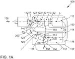
- an exhaust gas recirculation arrangement in two preferred embodiments with reference to Figures 1A and 1B described.
- Essential elements of the exhaust gas recirculation arrangement or system are the exhaust gas recirculation cooler 6, 118 as well as the first branch 10, 136 arranged downstream of the exhaust gas recirculation cooler 6, 118.
- a low-pressure exhaust gas recirculation path for an otherwise not shown internal combustion engine for recirculating exhaust gas (exhaust gas recirculation EGR) in a fresh air or combustion air mass flow
- ND-EGR path low-pressure exhaust gas recirculation path
- EGR exhaust gas recirculation EGR
- a turbine 110 of an exhaust gas turbocharger a catalyst 112nd an overflow housing 114
- a particulate filter 116 for example in the form of a diesel particulate filter
- EGR cooler 118 for example in the form of a diesel particulate filter
- EGR passage 120 for example in the form of a diesel particulate filter
- a point of introduction 122 for introducing recirculated exhaust gas 24 into a fresh air stream 126 having an EGR inlet port 128.
- a compressor 130 of the exhaust gas turbocharger a flange 132 between turbine 110 and catalytic converter 112, an exhaust gas flap 134 in a branching exhaust pipe 136, which serves to remove unreturned exhaust gas 138, an EGR valve 140 in the form of a throttle valve, an intake throttle valve 142, an EGR filter 144 in the form of a dome-shaped grille, a flange 146 between the particulate filter 116 and the EGR cooler 118, a support 148 for the exhaust gas turbocharger and an exhaust manifold 150, which is formed as a module integral with a turbine housing of the turbines 10, and a motor housing 152 of the internal combustion engine.
- a housing 137 accommodating the particle filter 116 has an integrated branch 135, to which the exhaust pipe 136 is connected.
- the EGR filter 144 is disposed on the flange 146 concentric therewith.
- the downstream arranged in the exhaust system Exhaust damper 134 is used to set a Abgasstau horru horres and is optionally integrated into the particulate filter 116 or flanged directly to this.
- the low-pressure EGR cooler 118 is longitudinally flowed through and slightly inclined so that condensate drains off if necessary and ventilation is ensured.
- the EGR cooler 118 is mounted directly on the particulate filter 116 without a further line piece.
- the EGR passage 120 is directly connected to an exhaust funnel of the EGR cooler 118 and is optionally made of a plastic.
- a primary objective of the invention is to reduce the flow resistance of the entire gas path from the turbine exit to the compressor inlet to an absolute minimum. Since in conventional exhaust gas turbochargers the compressor inlet is arranged coaxially and rectified with the turbine outlet, the recirculated exhaust gas 124 is in a closed circuit, as indicated by a dashed line L in Figure 1A indicated, led.
- the goal of the invention is to make the sum of all deflections not much larger than 3600.
- all through-flow components comprising the catalyst 112, the particulate filter 116, the EGR filter 144, the EGR cooler 118, the overflow housing 114 and the EGR valve 140 are arranged substantially circularly to each other.
- the angular differences between the flow directions of the incoming and outflowing gases to the flow direction of the respective aforementioned component are not more than 90 ° and the deflections are all in the same direction, for example in a clockwise direction, as in Figure 1A shown.
- the close-coupled catalytic converter 112 is arranged coaxially with the turbine wheel and fastened directly to the turbocharger housing or to the turbine 110. This also offers other benefits.
- the light-off behavior of the catalyst is optimal, since almost no heat is lost after the turbocharger, and the flow of the catalyst is very evenly distributed.
- a low-cost circular-section catalyst can be used.
- the catalytic converter 112 is connected directly to the particle filter 116 (DPF) by means of the flow-optimized overflow housing 114, which is arranged approximately parallel to the catalytic converter 112. Also, the particulate filter 116 is optionally formed for cost reasons with a circular cross-section.
- the unit of catalyst 112 and particulate filter 116 additionally encloses at least a portion of the exhaust manifold 50 such that catalyst 112 and particulate filter 116 are supplied with thermal energy from the exhaust manifold 50.
- This assembly is optionally isolated by a common heat shielding element. This simultaneously preserves the desired heat or thermal energy in the components catalytic converter 112 and particle filter 116 and protects adjacent vehicle and engine components against overheating.
- the EGR cooler 118 is longitudinally flowed through to reduce the flow resistance without inner deflections and grown directly to an outlet funnel of the particulate filter 116 to simplify the assembly and to avoid costly lines.
- the dynamic pressure (the kinetic energy) of the gases flowing out of the particle filter 116 additionally reduces the required pressure difference.
- the EGR cooler 118 may be arranged slightly inclined in a water cooling, inter alia, for venting the water space.
- the cross section of the EGR cooler 118 is preferably formed circular for cost reasons.
- the EGR filter 144 serves to keep particles out of the particulate filter 116 from the compressor 130 and from the engine.
- the EGR filter 144 is inserted and held, for example, as a dome-shaped or conical or planar fabric or mesh or wire directly into the connection point (flange) between particle filter 116 or housing 137 and EGR cooler 118.
- the ideally circular flange 146 has the largest possible diameter.
- the EGR passage 120 downstream of the EGR cooler 118 is made of plastic for cost reasons, for example.
- the EGR passage 120 has a harmonic cross-sectional shape and a harmonic, flow-optimized curvature course.
- the EGR valve 140 is longitudinally flowed through at least in the opened state and has a minimal flow resistance.
- the EGR valve 140 is formed as a throttle valve and optionally made of a plastic and optionally integrated into the EGR passage 120 or the inlet port 128.
- the inlet nozzle 128 is optionally also made of a plastic and optimized primarily to a minimum flow resistance.
- Inlet nozzle 128, intake throttle 142 (if required) and EGR valve 140 are preferably arranged in a common housing (for example made of plastic).
- Throttle valve 142 and EGR valve 140 are optionally actuated by a common actuator, so that, for example, first the EGR valve 140 is fully opened, and then additionally the intake throttle 142 is closed.
- the exhaust gas flap 134 is integrated directly in the outlet funnel of the particle filter 116 or flanged directly thereto. This makes it possible to use an automatic (spring-actuated) flap instead of an electric flap.
- the turbocharger support 148 is preferably screwed together on the engine side together with the particle filter 116 either on the intermediate flange 146 or on a slit in the particle filter 116. If thermal expansions have to be accommodated within the constructional unit of catalytic converter 112 and particle filter 116, sliding seats are provided between each catalytic converter 112 and turbine 110, catalytic converter 112 and overflow housing 114, overflow housing 114 and particle filter 116 or particle filter 116 and inlet point 122.
- the EGR cooler 118 is mounted, for example, by means of a bayonet closure on the intermediate flange 146 or on the outlet funnel of the particle filter 116.
- the pressure loss in the LP EGR line is reduced so far that the fuel consumption of the engine is not higher than in a high-performance engine with high-pressure EGR system and It can be dispensed with an electric control valve in the exhaust system and a high-pressure EGR system.
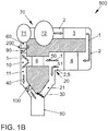
- FIG. 1B shows a further preferred embodiment of the construction of an exhaust system in an internal combustion engine with a focus on the arrangement of the exhaust gas recirculation arrangement according to the invention.
- the first branch 10 is followed by a first exhaust gas outlet 11 for discharging exhaust gas to the environment and a return line 60 for conducting exhaust gas in the direction of the exhaust gas turbocharger 70.
- the entire exhaust gas can pass through the exhaust gas recirculation cooler 6 and only after this into individual volume flows for the purpose of dissipation to the environment and supply to the exhaust gas turbocharger split.
- the inventive arrangement for exhaust gas recirculation with the other in FIG. 1B designed components. That is, it may include the exhaust gas turbocharger 70, from the turbine 72 exhaust gas exiting in the direction of the flow 1 and a catalyst 3 and downstream of the catalyst, a particulate filter 4 is supplied.
- the invention is not limited to the arrangement of a catalyst and a particulate filter.
- a fresh air system for supplying fresh air and exhaust gas mixture in the engine is in the FIG. 1B not shown.
- a second branch 20 Downstream of the particulate filter 4, a second branch 20 is provided, in which the volume flow is divided into the volume flow 50 through the exhaust gas recirculation cooler 6 and in the volume flow 51 to be derived.
- the volume flow through the exhaust gas recirculation cooler 50 is, as already described, downstream of the exhaust gas recirculation cooler 6 in the Volumetric flow of the exhaust gas in the first exhaust pipe 40 and in the gas flow attributable to the exhaust gas turbocharger 70 divided by the return line 60.
- This return line 60 connects to the compressor 71 of the exhaust gas turbocharger 70 and thus supplies the exhaust gas to the compressor so that it compresses the recirculated exhaust gas and optionally immediately mixed with fresh air and the internal combustion engine supplies.
- the second exhaust discharge line 21 thus branches off from the second branch 20 from the supply line 5, which transports the entire exhaust gas.
- the outgoing at the first branch 10 first exhaust gas discharge line 11 is connected for the purpose of weight and space savings with the second exhaust gas discharge line 21 in the junction 80.
- a first valve 30 is arranged in the second exhaust gas discharge line 21. This first valve 30 is in FIG. 1B shown in the closed position, so that the second exhaust gas outlet 21 is closed and thus the entire exhaust gas is passed through the exhaust gas recirculation cooler 6 and this consequently can utilize the entire amount of exhaust gas.
- the first valve 30 can be opened, so that exhaust gas is discharged to the environment in a greater or lesser extent by the second exhaust gas discharge in the volume flow 51 to be diverted.
- a second valve 90 is arranged in the recirculation line 60. Upon closure of this second valve 90, exhaust gas routed through the exhaust gas recirculation cooler 6 can not reach the compressor 71 flow, but must be discharged through the first exhaust discharge 11 to the environment.
- a third valve 100 can also be arranged in the first exhaust gas discharge line 11, with which the exhaust gas recirculation rate can be increased.
- the first valve 30 can be designed such that it as in FIG. 1B in a position, the second exhaust gas discharge line 21 completely closes and completely opens the first exhaust gas discharge line 11 and completely closes the first exhaust gas discharge line 11 and the second exhaust gas discharge line 21 completely opens, as indicated by the dashed line at the end of the first exhaust gas discharge line 11.
- the entire volume flow of the exhaust gas can pass through the exhaust gas recirculation cooler 6 and thus utilize the entire exhaust gas heat in it.
- the exhaust gas recirculation line 60 further includes a heat exchanger 200 configured to transfer heat from an exchange fluid to the exhaust gas recirculation line 60.
- the heat exchanger may, for example, as in the FIGS. 2 and 3 be formed represented.
- FIG. 2 shows a schematic representation of a longitudinal section of a heat exchanger 200 according to the invention in a preferred embodiment. Shown is a heat exchanger 200 according to the invention, which is arranged on an exhaust gas recirculation line 60.
- the heat exchanger 202 includes fluid flow channels 210 and 220, namely, a fluid supply channel 210 and a fluid discharge channel 220.
- these are aligned parallel to one another and parallel to the exhaust gas recirculation line 60.
- at least one of the fluid flow channels 210, 220 can be arranged at least partially tangentially around the exhaust gas recirculation line 60, wherein the tangential arrangement can be carried out as a repeating unit, so that the respective fluid flow channel 220 or 210 runs as a spiral around the exhaust gas recirculation line 60.
- the fluid supply passage 210 is fluidly connected to a fluid inlet 211 at a first end while the fluid discharge passage 220 is fluidly connected to a fluid outlet 221 at a first end.
- the fluid supply channel 10 and the fluid discharge channel 220 are connected in a fluid-conducting manner in the region of a transfer line 215, the transfer line 215 respectively at the second end of the respective fluid flow channel 210 or 220, ie at the end of the respective fluid flow channel 210, 220 facing away from the fluid outlet 221 or the fluid inlet 211 , is arranged.
- the fluid flow channels 210 and 220 extend substantially longitudinally and parallel to the direction of extension of the exhaust gas recirculation line 60.
- the replacement fluid guided in the flow channels 210, 220 experiences a reversal of the flow direction.
- the heat exchanger 200 is a three-shell design, with three shells refers to the arrangement of the flow channels 60, 210, 220 to each other.
- the inner shell is formed by the exhaust gas recirculation line 60, which is the center of the assembly.
- the second shell concentrically surrounding the first shell, ie the exhaust gas recirculation line 60 in the embodiment shown, is in the illustrated embodiment the fluid supply channel 210, which in turn is concentrically surrounded by the fluid discharge duct 220.
- the structure may therefore be described as being based on a pipe-in-pipe principle, with the diameter increasing from the inner shell or inner pipe (exhaust gas recirculation pipe 60) to the outer shell or pipe (fluid discharge duct 220).
- the exhaust gas recirculation line 60 is designed in the embodiment shown as a linearly extending tube. This is only a preferred embodiment or a section of the exhaust gas recirculation line 60 in an exhaust gas recirculation arrangement according to the invention. Beyond the simple design shown, the exhaust gas recirculation line 60 can also be designed as a curved or spiral pipe. In addition, an inner surface 61 of the exhaust gas recirculation line 60 is substantially smooth, that is formed without elevations, depressions or profiling. The term smoothly refers only to the surface texture and not on the course of the entire exhaust gas recirculation line 60. Thus, the inner surface 61 of a tortuous or kinked pipe can be smooth in the context of the invention.
- the heat exchanger 200 according to the invention is shown in a further preferred embodiment, wherein the exhaust gas recirculation arrangement in the region of the heat exchanger 200 is shown in cross section.
- the embodiment shown corresponds to FIG. 3 the in FIG. 2 shown embodiment.
- the heat exchanger 200 is arranged as a multi-shell structure around the exhaust gas recirculation line 60.
- the exhaust gas recirculation line 60 is surrounded by only one of the fluid flow channels 210, 220.
- One of the fluid flow channels 210, 220 in the illustrated embodiment forms the outer shell, which is in the form of a non-round tube 230.
- the exhaust gas recirculation line 60 and the second fluid flow channel 220, 210 are disposed adjacent to each other and parallel to the outer shell.
- the exhaust gas recirculation line 60 as well as in FIG. 2 embodiment shown against the replacement fluid so that no fluid exchange between the fluid flow passage 210, 220 and exhaust gas recirculation line 60 takes place.
- the two fluid flow channels 210, 220 are through a transfer line 215 (in FIG. 3 not shown) fluidly connected to each other. This can be realized by defining the second fluid flow channel 220, 210 by a tube or wall having a shorter length than the non-circular tube 230 bounding the first fluid flow channel 210 or 220.
- the exhaust gas recirculation arrangement 500 heat is transferred from the replacement fluid to the exhaust gas recirculation line 60 in the heat exchanger 200 and the exhaust gas recirculation line 60 is thus heated in this area.
- condensate and / or ice formation in the exhaust gas recirculation line 60 are effectively prevented and the downstream components are protected and prevents unwanted pressure reduction in the exhaust gas recirculation.
Landscapes
- Engineering & Computer Science (AREA)
- Mechanical Engineering (AREA)
- General Engineering & Computer Science (AREA)
- Chemical & Material Sciences (AREA)
- Combustion & Propulsion (AREA)
- Physics & Mathematics (AREA)
- Thermal Sciences (AREA)
- Exhaust-Gas Circulating Devices (AREA)
- Heat-Exchange Devices With Radiators And Conduit Assemblies (AREA)
Abstract
Description
- Die vorliegende Erfindung betrifft eine Einrichtung zur Abgasrückführung zur zumindest teilweisen Rückführung von Abgasen einer Verbrennungseinrichtung in den der Verbrennungseinrichtung zuzuführenden Gasstrom, die im Strömungskanal für das rückzuführende Abgas zur Abkühlung des Abgases und zur Ableitung von Abgaswärme einen Abgasrückführungskühler aufweist.
- Außerdem betrifft die vorliegende Erfindung eine Brennkraftmaschine, die eine erfindungsgemäße Einrichtung zur Abgasrückführung umfasst, sowie ein Kraftfahrzeug, welches wiederum die Brennkraftmaschine umfasst.
- Zur Verringerung von Stickoxid- und Rußemissionen von Verbrennungsmotoren mit Abgasturbo-Aufladung wird das entstandene Abgas stromabwärts der Turbine des Abgasturboladers beziehungsweise stromabwärts eines gegebenenfalls angeordneten Dieselpartikelfilters entnommen und stromaufwärts des Verdichters des Abgasturboladers der Ansaugluft zugeführt. Der Volumenstrom der Abgasrückführmenge wird üblicherweise mittels eines Abgasrückführungsventils geregelt, das in der Abgasrückführungsstrecke angeordnet ist. Um den Verdichter vor zu hohen Abgastemperaturen zu schützen, ist üblicherweise in der Abgasrückführungsstrecke zusätzlich ein Abgasrückführungskühler angeordnet, der unter Abführung von Abgaswärme das dem Verdichter zugeführte Abgas abkühlt. Diese Abgaskühlung hat den zusätzlichen Effekt der weiteren Reduktion von Stickoxiden im Abgas.
- Der Zweck der Abgasrückführung besteht in der Herstellung eines Gemisches aus Frischluft und Abgas, welches dem Verbrennungsprozess zugeführt wird und einen niedrigeren Sauerstoffgehalt aufweist als reine Frischluft, wodurch die Temperatur im Brennraum einer Verbrennungseinrichtung oder Brennkraftmaschine nicht mehr ein Niveau erreicht, bei dem Stickstoffoxid in der Menge gebildet wird, wie es bei reiner Frischluftzufuhr der Fall wäre.
- Einige der verwendeten Abgasrückführungskühler werden dafür eingesetzt, die bei der Abkühlung gewonnene Wärme des Abgases weiterer Nutzung, wie zum Beispiel zur Erwärmung der Brennkraftmaschine oder auch eines Fahrgastraumes eines mit der Brennkraftmaschine ausgestatteten Kraftfahrzeuges oder weiterer Gegenstände, zuzuführen.
- Die
EP 1 455 078 A1 offenbart eine Brennkraftmaschine mit einem Abgasturbolader und einem Abgasrückführungssystem, welches kostengünstig ausgestaltet ist und einen optimierten Motorbetrieb ermöglicht. Zu diesem Zweck ist neben einem Niederdruck-Rückführungspfad ein zusätzlicher Hochdruck-Rückführungspfad zur Ableitung des Abgases vorgesehen. - Die
DE 10 2004 061 809 A1 offenbart ein Heiz- und/oder Kühlsystem für ein Kraftfahrzeug, welches zwar keine Abgasrückführung aufweist, jedoch zur Erwärmung des Motors und/oder zur Beheizung des Kraftfahrzeuges einen extra Brenner einsetzt zur zusätzlichen Erwärmung des Abgases und Ableitung beziehungsweise Abnahme der Wärme des Abgases in einem Wärmetauscher. Durch den Einsatz des zusätzlichen Brenners wird jedoch das Gesamtgewicht der Brennkraftmaschine erhöht. Beim Betrieb des Brenners wird zusätzlicher Brennstoff verbraucht. - In der
DE 10 2006 054 043 A1 ist eine Brennkraftmaschine mit Abgasrückführung dargestellt, die einen Hochdruck- und einen Niederdruck-Rückführungspfad aufweist, wobei im Niederdruck-Rückführungspfad ein Abgasrückführungskühler angeordnet ist. Dieses Abgasrückführungssystem umfasst somit neben dem Abgasrückführungskühler eine erste Abgasableitung zur Ableitung von nicht rückgeführtem Abgas, die an einer ersten Abzweigung stromaufwärts des Abgasrückführungskühlers angeordnet ist. - Aus der
DE 10 2005 052 496 A1 ist eine Brennkraftmaschine mit einem Abgasturbolader bekannt, die im Abgasrückführungspfad einen Abgaskühler aufweist. Dabei sind die Abgasvolumenströme in ihrer Größe und Richtung durch den Abgasrückführungspfad unvariierbar vorgegeben. - Es besteht in den in Kraftfahrzeugen eingesetzten Brennkraftmaschinen zunehmend das Problem, dass Einrichtungen zur Abgasaufbereitung und Abgasrückführung räumlich von der Verbrennungseinheit stärker getrennt sind. Das darin geführte Abgas neigt durch den hohen Feuchtegehalt und die im Abgaskühler erniedrigte Temperatur zur Kondensation in der Abgasrückführungsleitung. Entstehendes Kondensat wiederum kann je nach Temperatur in der Abgasrückführungsleitung zu Eisbildung führen. Beides kann zu einer Verringerung des Leitungsquerschnitts führen, was insbesondere bei Niederdrucksystemen zu einem starken Druckverlust führt. Darüber hinaus führt Eis und Kondensat, welches in die nachgeschalteten Einrichtungen, insbesondere in den Turbolader gelangt, zu deren Schädigung.
-
DE 10 2008 015 591 A1 schlägt zur Lösung dieses Problems vor, dass die Abgasrückführung umgangen wird, wenn die Temperatur von Ansauggas zu niedrig ist. Dies löst jedoch nicht das Problem zu langer Abgasleitungen, da es dort auch bei erreichten Soll-Temperaturen zur Kondensation von Wasser an den Wänden der Leitungen kommt. - Der Erfindung liegt nun die Aufgabe zugrunde, eine Abgasrückführungsanordnung bereitzustellen, die die Nachteile des Stands der Technik behebt oder zumindest reduziert. Insbesondere soll eine Abgasrückführungsanordnung bereitgestellt werden, in der eine Kondensation von Feuchtigkeit beziehungsweise eine Eisbildung in einer Abgasrückführungsleitung wirksam verhindert wird.
- Diese Aufgabe wird durch eine Abgasrückführungsanordnung, einen Wärmetauscher sowie eine Brennkraftmaschine mit den Merkmalen der unabhängigen Ansprüche gelöst.
- Somit betrifft ein erster Aspekt der Erfindung eine Abgasrückführungsanordnung zur zumindest teilweisen Rückführung von Abgasen einer Verbrennungseinrichtung in den der Verbrennungseinrichtung zuzuführenden Gasstrom. Der Gasstrom wird in einem Strömungskanal geführt. Die Abgasrückführungsanordnung weist im Strömungskanal für das rückzuführende Abgas einen Abgasrückführungskühler zur Abkühlung des Abgases sowie zur Ableitung von Abgaswärme auf. Stromab des Abgasrückführungskühlers ist eine mit der Gasstromströmung technisch verbundene Abgasrückführungsleitung angeordnet. Diese befindet sich demnach strömungstechnisch zwischen Abgasrückführungskühler und einem Zustrom der Verbrennungseinrichtung. Erfindungsgemäß ist vorgesehen dass die Abgasrückführungsleitung einen Wärmetauscher zur Zuführung von Wärme aufweist.
- In der erfindungsgemäßen Abgasrückführungsanordnung ist eine Kondensatbildung nahezu vollständig unterbunden. Darüber hinaus findet insbesondere keine Eisbildung in der Abgasrückführungsleitung statt. Dies stellt den Schutz nachgeschalteter Bauteile sicher. Darüber hinaus wird ein Querschnitt des Strömungskanals und insbesondere der Abgasrückführungsleitung nicht durch Tröpfchen- oder Eisbildung verkleinert. Dies ist insbesondere bei Niederdruck-Abgasrückführungssystemen ein entscheidender Vorteil, da hier jegliche Verringerung des Querschnitts zu einem Druckabfall führen würde, der sich nachteilig auf den Wirkungsgrad der Abgasrückführungsanordnung auswirken würde, da der relativ tolerierbare Druckverlust deutlich geringer ist als bei Vergleichssystemen.
- Vorteilhafterweise wird das Wirkprinzip bestehender Wärmetauschertechnologien im Bereich der Abgastechnik umgekehrt, sodass nur wenig Umbauten erforderlich sind. In der Abgasrückführung werden bislang Wärmetauscher eingesetzt, die den Gasstrom kühlen, ihm also Wärme entziehen. Dazu sind sie auf eine höchstmögliche Wärmeübertragung zwischen dem im Wärmetauscher geführten Austauschfluid und dem in der Abgasleitung geführten Abgas ausgelegt. Hierzu ist üblicherweise die Oberfläche, an der die Übertragung stattfindet, nämlich die dem Abgas zugewandte Oberfläche der Abgasleitung, möglichst groß. Der Wärmeaustausch erfolgt dann vom Abgas über die möglichst große Oberfläche der Abgasleitung auf das Austauschfluid, welches im Zuge dessen erwärmt wird. Im erfindungsgemäßen Wärmetauscher hingegen erfolgt ein Wärmeaustausch vom Austauschfluid auf die Leitungswand.
- Die erfindungsgemäße Abgasrückführungsanordnung ermöglicht eine bessere Nutzung des zur Verfügung stehenden Bauraums in einer Brennkraftmaschine. Das heißt, der Bauraum kann weitgehend unabhängig davon genutzt werden, wie der Abgasrückführungskühler und ein Zustrom zur Verbrennungseinrichtung zueinander angeordnet und insbesondere beabstandet sind. Hieraus ergibt sich ein entscheidender Vorteil zu bestehenden Technologien. Bekannte Abgasrückführungsanordnungen, insbesondere solche im Niederdruckbereich, erfordern eine möglichst kurze Abgasrückführungsleitung, um die unvermeidliche Kondensatbeziehungsweise Eisbildung in der Abgasrückführungsleitung beziehungsweise deren Folgen möglichst zu reduzieren. Dies erfordert wiederum eine räumliche Nähe der in der Abgasrückführung miteinander verbundenen Komponenten. Die erfindungsgemäße Abgasrückführungsanordnung hingegen stellt auch für längere Abgasrückführungsleitungen, mit bis zu 70 Zentimetern Länge, eine Kondensat- und Eisfreiheit sicher.
- Der Wärmetauscher in der erfindungsgemäßen Abgasrückführungsanordnung weist ein Austauschfluid auf, welches thermisch mit der Abgasrückführungsleitung in Kontakt steht.
- In bevorzugter Ausgestaltung der Erfindung ist vorgesehen, dass der Wärmetauscher strömungstechnisch mit einem Kühlmittelkreislauf einer Verbrennungseinrichtung und/oder einer Abgasrückführung verbunden ist. Der Wärmetauscher kann demnach als Teil eines Kühlmittelkreislaufs der Verbrennungseinrichtung und/oder der Abgasrückführung angesehen werden. Das Austauschfluid des Wärmetauschers ist in diesem Fall das Kühlmittel des betreffenden Kühlmittelkreislaufs. Der Vorteil dieser Ausgestaltung liegt im Wesentlichen darin, dass kein zusätzlicher Fluidkreislauf notwendig wird und damit kein zusätzlicher Bauraum beansprucht werden muss. Zudem entfällt eine separate Erwärmungseinrichtung, um das Austauschfluid des Wärmetauschers auf eine definierte Solltemperatur zu bringen, die geeignet ist, die Abgasrückführungsleitung gegen Kondensation im Innenumfang zu schützen. Vielmehr wird Wärmeenergie genutzt, die beim Kühlen anderer Baugruppen, insbesondere der Verbrennungseinrichtung, frei wird.
- Für ein wirksames Unterbinden einer Kondensation im Innern der Abgasrückführungsleitung werden bevorzugt Einschaltbedingungen vorgesehen, die erfüllt sein müssen, um ein Passieren der Abgasrückführungsleitung zu erlauben, also ein entsprechendes Stellmittel in beziehungsweise stromauf der Abgasrückführungsleitung in Durchlassposition zu stellen. Bevorzugt wird die Einschaltbedingung als abhängig von einer Außentemperatur, einer Kühlertemperatur und/oder einer Abgastemperatur gewählt oder entspricht einem vordefinierten Wert einer solchen.
- Alternativ oder zusätzlich weist die Abgasrückführungsanordnung ein insbesondere steuerbares Stellmittel auf, welches bevorzugt zwischen Abgasrückführungskühler und Abgasrückführungsleitung angeordnet und ausgebildet ist, die Abgasrückführungsleitung zu verschließen. Das Stellmittel befindet sich mit Vorteil dann in einer Verschlussposition, wenn die Solltemperatur des Austauschfluids nicht erreicht ist. Dies ist insbesondere in Startphasen und bei stark reduzierter Außentemperatur der Fall. Der Durchfluss durch die Abgasrückführungsleitung ist demnach nur bei Erreichen einer sogenannten Einschaltbedingung, die sich insbesondere im Erreichen der Solltemperatur zeigt, ermöglicht. Diese Ausgestaltung stellt sicher, dass auch bei niedrigeren Kühlmittel- beziehungsweise Austauschfluid-Temperaturen die Abgasrückführungsleitung kondensat- und eisfrei bleibt.
- Im Weiteren soll unter Fluid stets auch das Austauschfluid in obiger Bedeutung verwendet werden.
- In einer weiter bevorzugten Ausgestaltung der Erfindung ist vorgesehen, dass der Wärmetauscher im Kühlmittelströmungskanal stromab des Abgasrückführungskühlers angeordnet ist. Diese Ausgestaltung ermöglicht eine weitere Effizienzsteigerung, da das Kühlmittel stromabwärts des Abgasrückführungskühlers eine höhere Temperatur aufweist und somit die im Kühlmittel gespeicherte Wärme an die Abgasrückführungsleitung übertragen werden kann.
- Mit Vorteil weist die Abgasrückführungsleitung im Bereich des Wärmetauschers eine glatte innere Oberfläche auf. Mit anderen Worten ist der Innenumfang der Abgasrückführungsleitung zumindest im Bereich des Wärmetauschers glatt, also ohne Erhebungen, Profilierungen oder Ausnehmungen, ausgeführt. Dies führt zum einen zu einem erhöhten effektiven Querschnitt der Abgasrückführungsleitung, was - wie oben beschrieben - insbesondere bei Niederdruck-Abgasrückführungssystemen von Vorteil ist. Darüber hinaus ist die Oberfläche zwischen Abgasrückführungsleitung und Abgas in dieser Ausgestaltung im Vergleich zu bekannten Geometrien in beziehungsweise Ausgestaltungen von Wärmetauschern, in denen Abgas gekühlt wird, möglichst klein. Daher wird möglichst wenig Wärme von der Abgasrückführungsleitung auf das Abgas übertragen, sodass der Effekt des stromauf der Abgasrückführungsleitung angeordneten Abgasrückführungskühlers, nämlich das Vorliegen eines gekühlten und somit komprimierten Abgases in der Abgasrückführungsanordnung, im Wesentlichen bestehen bleibt.
- In weiter bevorzugter Ausgestaltung der Erfindung ist vorgesehen, dass der Wärmetauscher über einen Fluideinlass und einen Fluidauslass verfügt, wobei der Fluideinlass und der Fluidauslass benachbart zueinander angeordnet sind. Vorliegend ist unter benachbart zu verstehen, dass sowohl der Fluideinlass als auch der Fluidauslass auf einer Seite, also am gleichen Ende des sich entlang der Abgasrückführungsleitung erstreckenden Wärmetauschers, angeordnet sind. Mit anderen Worten befinden sich sowohl Fluideinlass als auch Fluidauslass am gleichen Ende des Wärmetauschers bezogen auf die Erstreckungsrichtung der Abgasrückführungsleitung. In dieser Ausgestaltung sind weitere Bauraumvorteile nutzbar, da nicht sichergestellt werden muss, dass je ein Fluidanschluss (Fluideinlass oder Fluidauslass) an beiden Enden des Wärmetauschers angeordnet werden kann.
- Weiter ist vorgesehen, dass die Abgasrückführungsleitung, insbesondere im Bereich des Wärmetauschers eine Länge im Bereich von 50-700 mm, insbesondere im Bereich von 200-650 mm, bevorzugt im Bereich 250-600 mm aufweist. Abgasrückführungsanordnungen mit Abgasrückführungsleitungen der vorbeschriebenen Längen zeigten besonders große Effekte auf die Reduktion von Kondensat- und Eisbildung bei Verwendung des erfindungsgemäßen Wärmetauschers, wobei mit zunehmender Länge der relative Effekt auf den Wirkungsgrad zu nimmt. Mit zunehmender Länge der Abgasrückführungsleitung nimmt die Gefahr und Häufigkeit von Eisbildung zu, da sich das geführte Abgas abkühlt und so die Leitung weniger wärmt. Dieser Effekt wird durch die erfindungsgemäße Abgasrückführungsanordnung ausgeschaltet, sodass die Leitung in nahezu jeder Länge und jedem Verlauf ausgestaltet werden kann.
- Mit Vorteil verlaufen die Abgasrückführungsleitung, ein im Wärmetauscher angeordneter Fluidzuführungskanal und ein im Wärmetauscher angeordneter Fluidableitungskanal im Bereich des Wärmetauschers parallel zueinander und stehen zumindest paarweise miteinander thermisch in Kontakt. Dabei handelt es sich um eine besonders einfach ausführbare und effektive Anordnung der einzelnen Strömungskanäle (Abgasströmungskanal, Fluidzuführungskanal und Fluidableitungskanal). Alternativ ist einer der Fluidströmungskanäle spiralförmig um die Abgasrückführungsleitung herum angeordnet, wobei lokale Strömungsrichtungen tangential zur Abgasrückführungsleitung verlaufen und die effektive Strömungsrichtung, also die kumulierte Strömungsrichtung, parallel zu dieser verläuft. Diese Ausführungsform hat wiederum den Vorteil einer optimalen Bauraumausnutzung bei maximalem thermischen Kontakt. Zudem ermöglicht eine derartige Anordnung eine mehrschalige Ausgestaltung des Wärmetauschers. Hierbei sind unter Schalen die einzelnen Strömungskanäle zu verstehen, welche direkt aneinander angrenzen, insbesondere paarweise nur durch eine gemeinsame Wand voneinander getrennt sind. Dabei umgibt zumindest einer der Fluidströmungskanäle die Abgasrückführungsleitung bezogen auf deren Querschnitt.
- Besonders bevorzugt handelt es sich um eine dreischattige Anordnung, wobei die Abgasrückführungsleitung und somit der Abgasstrom als zentrale Schale beziehungsweise zentrales Rohr angeordnet ist, umgeben von einem der Fluidströmungskanäle, insbesondere dem Fluidzuführungskanal. Um diesen herum ist dann der andere Fluidströmungskanal, insbesondere der Fluidableitungskanal angeordnet. Mit anderen Worten sind zumindest zwei der Strömungskanäle verschachtelt ineinander angeordnet, wobei stets die Abgasrückführungsleitung von dem Austauschfluid umspült wird. Der Vorteil dieser Ausgestaltungen liegt insbesondere in der Umspülung der Abgasrückführungsleitung durch das Austauschfluid, da dies zum einen einen hohen Wirkungsgrad der Wärmeübertragung vom Fluid auf die Abgasleitung sicherstellt und zum anderen einen möglichst wenig komplexen Aufbau des Wärmetauschers ermöglicht.
- Eine den Fluidzuführungskanal vom Fluidableitungskanal trennende Wand ist bevorzugt in Strömungsrichtung längserstreckt, insbesondere konzentrisch um die Abgasrückführungsleitung ausgebildet und in einem Überführungsabschnitt unterbrochen. Im Überführungsabschnitt ist eine Überführung des Austauschfluids vom Zuführungskanal in den Fluidableitungskanal oder umgekehrt ermöglicht.
- Der Wirkungsgrad der Wärmeübertragung ist ferner optimiert, wenn der Fluidzuführungskanal zwischen Abgasrückführungsleitung und Fluidableitungskanal angeordnet ist. Dies ist der Fall, wenn der Fluidzuführungskanal die Abgasrückführungsleitung und der Fluidableitungskanal den Fluidzuführungskanal konzentrisch umgeben.
- In besonders bevorzugter Ausgestaltung ist somit vorgesehen, dass der Fluidzuführungskanal und/oder der Fluidableitungskanal die Abgasrückführungsleitung umgibt und angeordnet ist. Diese Ausgestaltung hat den Vorteil, dass nur ein Strömungskanal (Zuführung oder Ableitung) als geschlossener Kanal ausgeführt wird. Dabei ist nicht Voraussetzung, dass die Strömungskanäle einander konzentrisch umgeben. Vielmehr ist es auch möglich, dass die Abgasrückführungsleitung und einer der Fluidströmungskanäle einander benachbart angeordnet sind und gemeinsam von dem verbleibenden Fluidströmungskanal umgeben werden. Mit anderen Worten verläuft einer der Fluidströmungskanäle in dem anderen und geht in einem Abschnitt, vorzugsweise an einem Ende in den anderen über. In diesem Abschnitt ist demnach eine fluidführende Verbindung zwischen den beiden Fluidströmungskanälen vorgesehen. Vorzugsweise entspricht die fluidführende Verbindung einer Kehre, sodass sich die Strömungsrichtung des Austauschfluids, vorzugsweise 180° ändert. Diese Ausgestaltung ist eine besonders platzsparende und bezogen auf den thermischen Übergang sehr effiziente Ausgestaltung eines Wärmetauschers.
- Ein weiterer Aspekt der Erfindung betrifft einen Wärmetauscher zur Anordnung in der erfindungsgemäßen Abgasrückführungsanordnung. Der erfindungsgemäße Wärmetauscher weist eine zu wärmende oder zu kühlende Leitung auf, zu der benachbart ein Fluidströmungskanal verläuft, der den Fluss eines Austauschfluids definiert. Erfindungsgemäß weist der Fluidströmungskanal eine Fluidzuführung und eine Fluidableitung auf, welche zueinander und zu der Leitung parallel verlaufen und mit der Leitung und/oder miteinander thermisch in Kontakt stehen. Der erfindungsgemäße Wärmetauscher ist zur Anordnung in der erfindungsgemäßen Abgasrückführungsanordnung geeignet und ermöglicht eine Erwärmung der Leitung durch Wärmeübertragung von einem Austauschfluid auf die Leitung bei minimalem Platzbedarf und optimiertem thermischen Übergang. Zudem führt die Ausgestaltung dazu, dass engere Bauräume nutzbar sind, sodass beispielsweise das Anordnen eines Vorlaufes bezogen benachbart zur Abgasrückführungsleitung in einem Bereich, in dem der Durchmesser aufgrund der Anordnung der Fluidströmungskanäle zueinander reduziert ist (siehe beispielsweise
Figur 3 ). Bezogen aufFigur 3 ergäbe sich, dass die Fluidableitung als offener Strömungskanal ausgeführt ist, also die anderen beiden umgibt, ohne selbst in einem diskreten Rohr benachbart zu diesen geführt zu werden. - Die Anordnung der Fluidströmungskanäle im Sinne des genannten Rohr-im-Rohr-Prinzips hat zudem den Vorteil, dass das außen geführte Fluid, insbesondere das Austauschfluid, stets eine gewisse Isolationswirkung zwischen Außentemperatur und innerem Rohr hat, insbesondere rückzuführendem Abgas.
- Das Fluid wird im erfindungsgemäßen Wärmetauscher bevorzugt in einem ersten Abschnitt einer ersten Strömungsrichtung parallel zur Erstreckungsrichtung der Leitung geführt und in einem zweiten Abschnitt in einer der ersten Strömungsrichtung entgegengesetzten Strömungsrichtung, wiederum parallel zur Erstreckungsrichtung der Leitung, geführt, wobei beide Abschnitte vorzugsweise über eine Kehre strömungstechnisch miteinander verbunden sind.
- Der erfindungsgemäße Wärmetauscher wird bevorzugt in der erfindungsgemäßen Abgasrückführungsanordnung angeordnet. Alternativ ist er auch mit umgekehrtem Wirkprinzip, also zu einer Wärmeübertragung von einem in der Leitung geführten Fluid auf das Austauschfluid, einsetzbar.
- Ein weiterer Aspekt der Erfindung betrifft eine Brennkraftmaschine umfassend eine erfindungsgemäße Abgasrückführungsanordnung und oder einen erfindungsgemäßen Wärmetauscher.
- Weitere bevorzugte Ausgestaltungen der Erfindung ergeben sich aus den übrigen, in den Unteransprüchen genannten Merkmalen.
- Die verschiedenen in dieser Anmeldung genannten Ausführungsformen der Erfindung sind, sofern im Einzelfall nicht anders ausgeführt, mit Vorteil miteinander kombinierbar. Dies betrifft insbesondere die Ausgestaltungen des Wärmetauschers in seiner allgemeinen Form und in der speziellen Anwendung in der erfindungsgemäßen Abgasrückführungsanordnung.
- Die Erfindung wird nachfolgend in Ausführungsbeispielen anhand der zugehörigen Zeichnungen erläutert. Es zeigen:
- Figur 1A
- eine schematische Darstellung der Abgasrückführungsanordnung in einer bevorzugten Ausgestaltung der Erfindung,
- Figur 1B
- eine schematische Darstellung der Abgasrückführungsanordnung in einer weiteren bevorzugten Ausgestaltung der Erfindung,
- Figur 2
- eine schematische Darstellung eines Längsschnitts des erfindungsgemäßen Wärmetauschers in einer bevorzugten Ausführungsform, und
- Figur 3
- eine schematische Darstellung eines Querschnitts des erfindungsgemäßen Wärmetauschers in einer weiteren bevorzugten Ausführungsform.
- Zunächst wird der Aufbau einer Abgasrückführungsanordnung in zwei bevorzugten Ausgestaltungen anhand der
Figuren 1A und1B beschrieben. Wesentliche Elemente der Abgasrückführungsanordnung beziehungsweise -systems sind der Abgasrückführungskühler 6, 118 sowie die stromabwärts des Abgasrückführungskühlers 6, 118 angeordnete erste Abzweigung 10, 136. - Die in
Figur 1A dargestellte, bevorzugte Ausführungsform einer erfindungsgemäßen Niederdruck-Abgasrückführungs-Strecke (ND-AGR-Strecke) für eine ansonsten nicht näher dargestellte Brennkraftmaschine zum Rückführen von Abgas (Abgasrückführung- AGR) in einen Frischluft- beziehungsweise Verbrennungsluftmassenstrom umfasst eine Turbine 110 eines Abgasturboladers, einen Katalysator 112, ein Überströmgehäuse 114, einen Partikelfilter 116, beispielsweise in Form eines Dieselpartikelfilters, einen AGR-Kühler 118, eine AGR-Leitung 120 und eine Einleitstelle 122 zum Einleiten von rückgeführtem Abgas 24 in einen Frischluftstrom 126 mit einem AGR-Einleitungsstutzen 128. - Weiterhin ist in
Figur 1A dargestellt ein Verdichter 130 des Abgasturboladers, ein Flansch 132 zwischen Turbine 110 und Katalysator 112, eine Abgasstauklappe 134 in einem abzweigenden Abgasrohr 136, welches zum Abführen von nicht rückgeführtem Abgas 138 dient, ein AGR-Ventil 140 in Form einer Drosselklappe, eine Ansaugdrosselklappe 142, ein AGR-Filter 144 in Form eines kalottenförmigen Gitters, einen Flansch 146 zwischen dem Partikelfilter 116 und dem AGR-Kühler 118, eine Stütze 148 für den Abgasturbolader und einen Abgaskrümmer 150, der als Modul einstückig mit einem Turbinengehäuse der Turbinen 10 ausgebildet ist, und ein Motorgehäuse 152 der Brennkraftmaschine. - Ein den Partikelfilter 116 aufnehmendes Gehäuse 137 weist eine integrierte Abzweigung 135 auf, an welche das Abgasrohr 136 angeschlossen ist. Das AGR-Filter 144 ist am Flansch 146 konzentrisch zu diesem angeordnet. Die stromabwärts in der Abgasanlage angeordnete Abgasstauklappe 134 dient zum Einstellen eines Abgasstaudruckes und ist optional in den Partikelfilter 116 integriert beziehungsweise an diesen direkt angeflanscht. Der Niederdruck-AGR-Kühler 118 ist längs durchströmt und leicht geneigt, damit gegebenenfalls Kondensat abläuft und eine Entlüftung sichergestellt ist. Der AGR-Kühler 118 ist ohne ein weiteres Leitungsstück direkt am Partikelfilter 116 montiert. Die AGR-Leitung 120 ist direkt mit einem Austrittstrichter des AGR-Kühlers 118 verbunden und ist optional aus einem Kunststoff gefertigt.
- Ein primäres Ziel der Erfindung besteht darin, den Strömungswiderstand der gesamten Gas-Strecke vom Turbinenaustritt bis zum Verdichtereintritt auf ein absolutes Minimum zu verringern. Da bei gängigen Abgasturboladern der Verdichtereintritt koaxial und gleichgerichtet mit dem Turbinenaustritt angeordnet ist, wird das zurückzuführende Abgas 124 in einem geschlossenen Kreislauf, wie durch eine strichpunktierte Linie L in
Figur 1A angedeutet, geführt. - Da jede Umlenkung einen unerwünschten Widerstand erzeugt, ist es das Ziel der Erfindung, die Summe aller Umlenkungen nicht viel größer als 3600 werden zu lassen. Hierzu sind alle durchströmten Komponenten, die den Katalysator 112, den Partikelfilter 116, den EGR-Filter 144, den EGR-Kühler 118, das Überströmgehäuse 114 und das EGR-Ventil 140 umfassen, im Wesentlichen kreisförmig zueinander angeordnet. Die Winkeldifferenzen zwischen den Strömungsrichtungen der ein- und ausströmenden Gase zu der Durchströmungsrichtung des jeweiligen zuvor genannten Bauteils betragen nicht mehr als jeweils 90° und die Ablenkungen erfolgen alle in derselben Richtung, beispielsweise im Uhrzeigersinn, wie in
Figur 1A dargestellt. - Der motornahe Katalysator 112 ist koaxial zum Turbinenrad angeordnet und direkt am Turboladergehäuse beziehungsweise an der Turbine 110 befestigt. Dies bietet darüber hinaus weitere Vorteile. Das Anspringverhalten des Katalysators ist optimal, da nahezu keine Wärme nach dem Turbolader verloren geht, und die Anströmung des Katalysators ist sehr gleich verteilt.
- Außerdem lässt sich ein kostengünstiger Katalysator mit kreisförmigem Querschnitt verwenden.
- Der Katalysator 112 ist mittels des strömungsoptimierten Überströmgehäuses 114 direkt mit dem Partikelfilter 116 (DPF) verbunden, der annähernd parallel zum Katalysator 112 angeordnet ist. Auch der Partikelfilter 116 ist wahlweise aus Kostengründen mit einem kreisförmigen Querschnitt ausgebildet.
- Die Einheit aus Katalysator 112 und Partikelfilter 116 umschließt zusätzlich mindestens einen Abschnitt des Abgaskrümmers 50, sodass Katalysator 112 und Partikelfilter 116 vom Abgaskrümmer 50 mit thermischer Energie versorgt werden. Diese Baueinheit wird optional durch ein gemeinsames Wärmeabschirmelement isoliert. Dies erhält gleichzeitig die gewünschte Wärme beziehungsweise thermische Energie in den Bauteilen Katalysator 112 und Partikelfilter 116 und schützt angrenzende Fahrzeug- und Motorbauteile vor Überhitzung.
- Der AGR-Kühler 118 ist zur Verringerung des Strömungswiderstandes ohne innere Umlenkungen längs durchströmt und zur Vereinfachung der Montage und zur Vermeidung kostspieliger Leitungen direkt an einen Austrittstrichter des Partikelfilters 116 angebaut. Der Staudruck (die kinetische Energie) der aus dem Partikelfilter 116 ausströmenden Gase reduziert zusätzlich die benötigte Druckdifferenz. Der AGR-Kühler 118 kann bei einer Wasserkühlung unter anderem zur Entlüftung des Wasserraumes leicht geneigt angeordnet sein. Der Querschnitt des AGR-Kühlers 118 ist bevorzugt aus Kostengründen kreisförmig ausgebildet.
- Der AGR-Filter 144 dient zum Fernhalten von Partikeln aus dem Partikelfilter 116 vom Verdichter 130 und vom Motor. Der AGR-Filter 144 ist beispielsweise als kalottenförmiges oder kegeliges oder planes Gewebe oder Geflecht oder Sieb direkt in die Verbindungsstelle (Flansch) zwischen Partikelfilter 116 beziehungsweise Gehäuse 137 und AGR-Kühler 118 eingelegt und gehalten. Zur Verringerung des Strömungswiderstandes weist der idealerweise kreisrunde Flansch 146 einen möglichst großen Durchmesser auf.
- Die AGR-Leitung 120 stromabwärts des AGR-Kühlers 118 ist aus Kostengründen beispielsweise aus einem Kunststoff gefertigt. Die AGR-Leitung 120 weist einen harmonischen Querschnittsverlauf und einen harmonischen, strömungsoptimierten Krümmungsverlauf auf.
- Das AGR-Ventil 140 ist zumindest im geöffneten Zustand längsdurchströmt und weist einen minimalen Strömungswiderstand auf. Bevorzugt ist das AGR-Ventil 140 als Drosselklappe ausgebildet und gegebenenfalls aus einem Kunststoff gefertigt und optional in die AGR-Leitung 120 oder den Einleitstutzen 128 integriert.
- Der Einleitstutzen 128 ist optional ebenfalls aus einem Kunststoff hergestellt und primär auf einen minimalen Strömungswiderstand optimiert. Einleitstutzen 128, Ansaug-Drosselklappe 142 (soweit erforderlich) und AGR-Ventil 140 sind bevorzugt in einem gemeinsamen Gehäuse (beispielsweise aus Kunststoff) angeordnet. Drosselklappe 142 und AGR-Ventil 140 werden optional von einem gemeinsamen Steller betätigt, sodass beispielsweise zunächst das AGR-Ventil 140 voll geöffnet wird, und danach zusätzlich die Ansaug-Drosselklappe 142 geschlossen wird. Die Abgasstauklappe 134 ist, sofern noch erforderlich, direkt im Austrittstrichter des Partikelfilters 116 integriert oder direkt an diesen angeflanscht. Hierdurch ist es möglich, eine selbsttätige (federbetätigte) Klappe anstatt einer elektrischen Klappe einzusetzen.
- Die Turboladerstütze 148 ist bevorzugt motorseitig zusammen mit dem Partikelfilter 116 entweder an dem Zwischenflansch 146 oder an einem Butzen im Partikelfilter 116 verschraubt. Falls innerhalb der Baueinheit aus Katalysator 112 und Partikelfilter 116 Wärmedehnungen aufgenommen werden müssen, sind Schiebesitze zwischen jeweils Katalysator 112 und Turbine 110, Katalysator 112 und Überströmgehäuse 114, Überströmgehäuse 114 und Partikelfilter 116 oder Partikelfilter 116 und Einleitstelle 122 vorgesehen. Der AGR-Kühler 118 ist beispielsweise mittels eines Bajonett-Verschlusses am Zwischenflansch 146 beziehungsweise am Ausgangstrichter des Partikelfilter 116 montiert.
- Durch die erfindungsgemäße für ein ND-AGR- System optimierte Anordnung und Ausführung aller beteiligten Bauteile wird der Druckverlust in der ND-AGR-Strecke soweit verringert, dass der Kraftstoffverbrauch des Motors nicht höher ist als bei einem leistungsgleichen Motor mit Hochdruck-AGR-System und es kann auf eine elektrische Regelklappe im Abgasstrang sowie auf ein Hochdruck-AGR-System verzichtet werden.
-
Figur 1B zeigt eine weitere bevorzugte Ausführung des Aufbaus einer Abgasanlage in einer Verbrennungskraftmaschine mit Fokus auf die Anordnung der erfindungsgemäßen Abgasrückführungsanordnung. An die erste Abzweigung 10 schließt sich eine erste Abgasableitung 11 zur Ableitung von Abgas an die Umgebung an sowie eine Rückführungsleitung 60 zur Leitung von Abgas in Richtung des Abgas-Turboladers 70. Somit lässt sich das gesamte Abgas durch den Abgasrückführungskühler 6 leiten und erst nach diesem in einzelne Volumenströme zwecks Ableitung an die Umgebung und Zuleitung zum Abgas-Turbolader aufteilen. - Vorteilhafterweise ist die erfindungsgemäße Anordnung zur Abgasrückführung mit den weiteren in
Figur 1B dargestellten Komponenten ausgestaltet. Das heißt, dass sie den Abgas-Turbolader 70 umfassen kann, aus dessen Turbine 72 Abgas in Richtung der Strömung 1 austritt und einem Katalysator 3 und stromabwärts des Katalysators einem Partikelfilter 4 zugeführt wird. Dabei ist die Erfindung nicht auf die Anordnung eines Katalysators und eines Partikelfilters eingeschränkt. Eine Frischluftanlage zur Zuführung von Frischluft- und Abgasgemisch in den Motor ist dabei in derFigur 1B nicht dargestellt. - Die Zuleitung des Abgases zu den einzelnen dargestellten Komponenten erfolgt mittels strömungstechnischer Verbindungen 2, wie zum Beispiel Leitungen, und/oder durch integrale Anordnung verschiedener Komponenten in einem Gehäuse.
- Stromabwärts des Partikelfilters 4 ist eine zweite Abzweigung 20 vorgesehen, in der der Volumenstrom aufgeteilt wird in den Volumenstrom 50 durch den Abgasrückführungskühler 6 sowie in den abzuleitenden Volumenstrom 51. Der Volumenstrom durch den Abgasrückführungskühler 50 wird, wie bereits beschrieben, stromabwärts des Abgasrückführungskühlers 6 in den Volumenstrom des Abgases in der ersten Abgasleitung 40 sowie in den zum Abgasturbolader 70 zurückzuführenden Gasstrom durch die Rückführungsleitung 60 aufgeteilt. Diese Rückführungsleitung 60 schließt an den Verdichter 71 des Abgas-Turboladers 70 an und führt somit das Abgas dem Verdichter zu, sodass dieser das zurückgeführte Abgas verdichtet und gegebenenfalls gleich mit Frischluft vermischt und der Brennkraftmaschine zuführt.
- Die zweite Abgasableitung 21 zweigt somit von der zweiten Abzweigung 20 von der Zuleitung 5 ab, die das gesamte Abgas transportiert. Die an der ersten Abzweigung 10 abgehende erste Abgasableitung 11 ist zwecks Gewichts- und Bauraumeinsparung mit der zweiten Abgasableitung 21 in der Einmündung 80 verbunden. Zur Regelung des Volumenstromes durch den Abgasrückführungskühler 6 ist in der zweiten Abgasableitung 21 ein erstes Ventil 30 angeordnet. Dieses erste Ventil 30 ist in
Figur 1B in geschlossener Stellung dargestellt, sodass die zweite Abgasableitung 21 geschlossen ist und somit das gesamte Abgas durch den Abgasrückführungskühler 6 geleitet wird und dieser demzufolge die gesamte Menge des Abgases verwerten kann. - Ist eine Verwertung der Wärme des genannten Abgases durch den Abgasrückführungskühler nicht gewünscht, kann das erste Ventil 30 geöffnet werden, sodass Abgas in verstärktem oder vollständigem Maß durch die zweite Abgasableitung im abzuleitenden Volumenstrom 51 an die Umgebung abgeleitet wird.
- Zur Einstellung, wieviel zurückzuführendes Abgas nach vollständiger Verwertung im Abgasrückführungskühler 6 dem Verdichter 71 des Abgas-Turbo-Laders 70 zugeführt wird, ist in der Rückführungsleitung 60 ein zweites Ventil 90 angeordnet. Bei Schließung dieses zweiten Ventils 90 kann durch den Abgasrückführungskühler 6 geleitetes Abgas nicht zum Verdichter 71 strömen, sondern muss durch die erste Abgasableitung 11 an die Umgebung abgeleitet werden.
- Ergänzend kann außerdem in der ersten Abgasableitung 11 ein drittes Ventil 100 angeordnet sein, mit welchem die Abgasrückführrate erhöht werden kann.
- Das erste Ventil 30 kann dabei derart ausgestaltet sein, dass es wie in
Figur 1B in einer Position die zweite Abgasableitung 21 vollständig schließt und dabei die erste Abgasableitung 11 vollständig öffnet und bei Umschaltung die erste Abgasableitung 11 vollständig schließt und die zweite Abgasableitung 21 vollständig öffnet, wie es mit der gestrichelten Linie am Ende der ersten Abgasableitung 11 angedeutet ist. - Insbesondere in dieser Ausgestaltung erübrigt sich die Anordnung des bereits erwähnten dritten Ventils.
- Mittels der erfindungsgemäßen Abgasrückführungsanordnung lassen sich bei Schließung des ersten Ventils 30 der gesamte Volumenstrom des Abgases durch den Abgasrückführungskühler 6 hindurchführen und somit die gesamte Abgaswärme in diesem nutzen.
- Die Abgasrückführungsleitung 60 weist zudem einen Wärmetauscher 200 auf, der eingerichtet ist, Wärme von einem Austauschfluid auf die Abgasrückführungsleitung 60 zu übertragen. Der Wärmetauscher kann beispielsweise wie in den
Figuren 2 und 3 dargestellt ausgebildet sein. - Es wird besonders hervorgehoben, dass die oben beschriebene Anordnung nur eine Ausführungsform der erfindungsgemäßen Abgasrückführungsanordnung beschreibt.
- Erfindungswesentlich ist jedoch lediglich die erfindungsgemäße Anordnung des Wärmetauschers 200, welcher an der Abgasrückführungsleitung 60, also in einem Bereich stromab des Abgasrückführungskühlers 6, insbesondere stromab der Abzweigung 10 und stromauf der Verbrennungseinheit beziehungsweise des Abgasturboladers 70 angeordnet ist.
-
Figur 2 zeigt eine schematische Darstellung eines Längsschnitts eines erfindungsgemäßen Wärmetauschers 200 in einer bevorzugten Ausführungsform. Gezeigt ist ein erfindungsgemäßer Wärmetauscher 200, der an eine Abgasrückführungsleitung 60 angeordnet ist. In der gezeigten Ausführungsform umfasst der Wärmetauscher 202 Fluidströmungskanäle 210 und 220, nämlich einen Fluidzuführungskanal 210 und einen Fluidableitungskanal 220. - Diese sind in der gezeigten Ausführungsform parallel zueinander und parallel zur Abgasrückführungsleitung 60 ausgerichtet. Alternativ dazu kann zumindest einer der Fluidströmungskanäle 210, 220 zumindest bereichsweise tangential um die Abgasrückführungsleitung 60 angeordnet sein, wobei die tangentiale Anordnung als Wiederholeinheit ausgeführt werden kann, sodass der betreffende Fluidströmungskanal 220 oder 210 als Spirale um die Abgasrückführungsleitung 60 verläuft.
- Der Fluidzuführungskanal 210 ist an einem ersten Ende mit einem Fluideinlass 211 fluidführend verbunden, während der Fluidableitungskanal 220 an einem ersten Ende fluidführend mit einem Fluidauslass 221 verbunden ist. Der Fluidzuführungskanal 10 und der Fluidableitungskanal 220 sind im Bereich einer Überleitung 215 fluidführend miteinander verbunden, wobei die Überleitung 215 jeweils am zweiten Ende des betreffenden Fluidströmungskanals 210 beziehungsweise 220, also an dem dem Fluidauslass 221 beziehungsweise dem Fluideinlass 211 abgewandten Ende des jeweiligen Fluidströmungskanals 210, 220, angeordnet ist. In der gezeigten Ausführungsform verlaufen die Fluidströmungskanäle 210 und 220 im Wesentlichen längserstreckt und parallel zur Erstreckungsrichtung der Abgasrückführungsleitung 60. Im Bereich der Überleitung 215 erfährt das in den Strömungskanälen 210, 220 geführte Austauschfluid eine Umkehr der Strömungsrichtung. Dies kann dadurch realisiert sein, dass die Strömungskanäle 210, 220 und 60 ineinander verschachtelt angeordnet sind, wobei eine Trennwand zwischen Fluidzuführungskanal 210 und Fluidableitungskanal 220 im Bereich der Überleitung 215 unterbrochen ist und somit die fluidführende Verbindung zwischen Fluidzuführungskanal 210 und Fluidableitungskanal 220 ausgebildet wird.
- Bei der in
Figur 2 gezeigten Ausführungsform des erfindungsgemäßen Wärmetauschers 200 handelt es sich um eine dreischalige Ausgestaltung, wobei sich dreischalig auf die Anordnung der Strömungskanäle 60, 210, 220 zueinander bezieht. Die innere Schale wird durch die Abgasrückführungsleitung 60 ausgebildet, welche das Zentrum der Anordnung darstellt. Die die erste Schale, also in der gezeigten Ausführungsform die Abgasrückführungsleitung 60, konzentrisch umgebende zweite Schale ist in der gezeigten Ausführungsform der Fluidzuführungskanal 210, welcher wiederum konzentrisch vom Fluidableitungskanal 220 umgeben wird. Der Aufbau kann demnach als auf einem Rohr-im-Rohr-Prinzip basierend beschrieben werden, wobei der Durchmesser ausgehend von der inneren Schale beziehungsweise des inneren Rohres (Abgasrückführungsleitung 60) hin zur äußeren Schale beziehungsweise Rohr (Fluidableitungskanal 220) ansteigt. - Die Abgasrückführungsleitung 60 ist in der gezeigten Ausgestaltung als linear verlaufendes Rohr ausgeführt. Dabei handelt es sich nur um eine bevorzugte Ausführungsform beziehungsweise um einen Ausschnitt der Abgasrückführungsleitung 60 in einer erfindungsgemäßen Abgasrückführungsanordnung. Über die gezeigte einfache Ausführung hinaus kann die Abgasrückführungsleitung 60 auch als gebogenes oder gewundenes Rohr ausgeführt sein. Zudem ist eine innere Oberfläche 61 der Abgasrückführungsleitung 60 im Wesentlichen glatt, also ohne Erhebungen, Vertiefungen oder Profilierung ausgebildet. Dabei bezieht sich die Bezeichnung glatt lediglich auf die Oberflächenbeschaffenheit und nicht auf den Verlauf der gesamten Abgasrückführungsleitung 60. So kann auch die innere Oberfläche 61 eines gewundenen oder geknickten Rohres glatt im Sinne der Erfindung sein.
- In
Figur 3 ist der erfindungsgemäße Wärmetauscher 200 in einer weiteren bevorzugten Ausführungsform gezeigt, wobei die Abgasrückführungsanordnung im Bereich des Wärmetauschers 200 im Querschnitt dargestellt ist. Im Wesentlichen entspricht die gezeigte Ausführungsform derFigur 3 der inFigur 2 gezeigten Ausführungsform. Ebenso wie inFigur 2 ist der Wärmetauscher 200 als mehrschaliger Aufbau um die Abgasrückführungsleitung 60 angeordnet. Im Unterschied zu der inFigur 2 gezeigten Ausführungsform ist die Abgasrückführungsleitung 60 jedoch lediglich von einem der Fluidströmungskanäle 210, 220 umgeben. Einer der Fluidströmungskanäle 210, 220 bildet in der gezeigten Ausführungsform die äußere Schale, welche in Form eines nicht runden Rohres 230 ausgebildet ist. Innerhalb dieses nicht runden Rohres 230 sind die Abgasrückführungsleitung 60 und der zweite Fluidströmungskanal 220, 210 benachbart zueinander und parallel zur äußeren Schale angeordnet. Dabei ist die Abgasrückführungsleitung 60 ebenso wie der inFigur 2 gezeigten Ausführungsform gegen das Austauschfluid abgeschlossen, sodass kein Fluidaustausch zwischen Fluidströmungskanal 210, 220 und Abgasrückführungsleitung 60 erfolgt. Die beiden Fluidströmungskanäle 210, 220 hingegen sind durch eine Überleitung 215 (inFigur 3 nicht gezeigt) fluidführend miteinander verbunden. Dies kann dadurch realisiert werden, dass der zweite Fluidströmungskanal 220, 210 durch ein Rohr oder eine Wand begrenzt ist, welche/s eine geringere Länge aufweist als das nicht runde Rohr 230, welches den ersten Fluidströmungskanal 210 oder 220 begrenzt. Zur optimalen Reduzierung von Strömungswiderständen, insbesondere im Bereich der Überleitung ist von Vorteil, wenn in der Ausführungsform derFigur 3 die äußere Schale 230, also das nicht runde Rohr, die Fluidableitung 220 begrenzt und die Zuführung des Austauschfluids über die im Innern der äußeren Schale 230 angeordnete, insbesondere als verkürztes Rohr oder Wand ausgeführte, Fluidzuführung 210 erfolgt. - In der erfindungsgemäßen Abgasrückführungsanordnung 500 wird im Wärmetauscher 200 Wärme vom Austauschfluid auf die Abgasrückführungsleitung 60 übertragen und die Abgasrückführungsleitung 60 somit in diesem Bereich erwärmt. Somit werden wirkungsvoll eine Kondensat- und/oder Eisbildung in der Abgasrückführungsleitung 60 verhindert und die nachgeschalteten Bauteile geschont sowie eine ungewollte Druckminderung in der Abgasrückführung verhindert.
-
- 500
- Abgasrückführungsanordnung
- 1
- Richtung der Strömung
- 2
- strömungstechnische Verbindung
- 3
- Katalysator
- 4
- Partikelfilter
- 5
- Zuleitung
- 6
- Abgasrückführungskühler
- 10
- erste Abzweigung
- 11
- erste Abgasableitung
- 20
- zweite Abzweigung
- 21
- zweite Abgasableitung
- 30
- erstes Ventil
- 31
- Klappe
- 32
- Gelenk
- 40
- Volumenstrom des Abgases in der ersten Abgasableitung
- 50
- Volumenstrom durch den Abgasrückführungskühler
- 51
- abzuleitender Volumenstrom
- 60
- Rückführungsleitung
- 61
- innere Oberfläche
- 70
- Abgasturbolader
- 71
- Verdichter
- 72
- Turbine
- 80
- Einmündung
- 90
- zweites Ventil
- 100
- drittes Ventil
- 110
- Turbine
- 112
- Katalysator
- 114
- Überströmgehäuse
- 116
- Partikelfilter
- 118
- Abgasrückführungskühler
- 120
- Abgasrückführungsleitung
- 122
- Einleitstelle
- 124
- rückgeführtes Abgas
- 126
- Frischluftstrom
- 128
- AGR-Einleitstutzen
- 130
- Verdichter
- 132
- Flansch
- 134
- Abgasstauklappe
- 135
- integrierte Abzweigung
- 136
- abzweigendes Abgasrohr
- 137
- Gehäuse
- 138
- nicht rückgeführtes Abgas
- 140
- AGR-Ventil
- 142
- Ansaugdrosselklappe
- 144
- Filter
- 146
- Flansch
- 148
- Stütze
- 150
- Abgaskrümmer
- 152
- Motorgehäuse
- 200
- Wärmetauscher
- 210
- Fluidzuführungskanal
- 211
- Fluideinlass
- 215
- Überleitung/Kehre
- 220
- Fluidableitungskanal
- 221
- Fluidauslass
- 230
- äußere Schale/nicht rundes Rohr
Claims (11)
- Abgasrückführungsanordnung (500) zur zumindest teilweisen Rückführung von Abgasen einer Verbrennungseinrichtung in den der Verbrennungseinrichtung zuzuführenden Gasstrom, die im Strömungskanal für das rückzuführende Abgas einen Abgasrückführungskühler (6, 118) zur Abkühlung des Abgases und zur Ableitung von Abgaswärme aufweist, wobei stromabwärts des Abgasrückführungskühlers (6, 118) eine mit dem Gasstrom strömungstechnisch verbundene Abgasrückführungsleitung (60, 120) angeordnet ist, dadurch gekennzeichnet, dass die Abgasrückführungsleitung (60, 120) einen von einem Austauschfluid durchströmten Wärmetauscher (200) zur Zuführung von Wärme in die den Gasstrom begrenzende Abgasrückführungsleitung (60, 120) aufweist.
- Abgasrückführungsanordnung (500) nach Anspruch 1, dadurch gekennzeichnet, dass das Austauschfluid ein Kühlmittel, insbesondere ein in einem Kühlkreislauf der Verbrennungseinrichtung und/oder des Abgasrückführungskühlers geführtes Kühlmittel, ist.
- Abgasrückführungsanordnung (500) nach Anspruch 2, dadurch gekennzeichnet, dass der Wärmetauscher (200) in einem Fluidströmungskanal des Kühlkreislaufs stromabwärts des Abgasrückführungskühlers (6, 118) angeordnet ist.
- Abgasrückführungsanordnung (500) nach einem der vorhergehenden Ansprüche, dadurch gekennzeichnet, dass die Abgasrückführungsleitung (60, 120) im Bereich des Wärmetauschers (200) eine glatte innere Oberfläche (61) aufweist.
- Abgasrückführungsanordnung (500) nach einem der vorhergehenden Ansprüche, dadurch gekennzeichnet, dass der Wärmetauscher (200) über einen Fluideinlass (211) und einen Fluidauslass (221) verfügt, wobei der Fluideinlass (211) und der Fluidauslass (221) benachbart zueinander angeordnet sind.
- Abgasrückführungsanordnung (500) nach einem der vorhergehenden Ansprüche, dadurch gekennzeichnet, dass das Abgas durch die Abgasrückführungsleitung (60, 180) geleitet wird, wenn das Austauschfluid an einem Fluideinlass (211), die Umgebungsluft und/oder das Kühlmittel eine Mindesttemperatur erreicht oder überschreitet.
- Abgasrückführungsanordnung (500) nach einem der vorhergehenden Ansprüche, dadurch gekennzeichnet, dass die Abgasrückführungsleitung (60, 120), ein Fluidzuführungskanal (210) und ein Fluidableitungskanal (220) parallel zueinander verlaufen und zumindest paarweise thermisch miteinander in Kontakt stehen.
- Abgasrückführungsanordnung (500) nach Anspruch 7, dadurch gekennzeichnet, dass der Fluidzuführungskanal (210) zwischen Abgasrückführungsleitung (60) und Fluidableitungskanal (220) angeordnet ist.
- Abgasrückführungsanordnung (500) nach Anspruch 7, dadurch gekennzeichnet, dass der Fluidzuleitungskanal (210) und/oder der Fluidableitungskanal (220) die Abgasrückführungsleitung (60, 120) umgebend angeordnet sind.
- Wärmetauscher (200) zur Anordnung in einer Abgasrückführungsanordnung (500) nach einem der vorhergehenden Ansprüche, aufweisend eine zu wärmende oder zu kühlende Leitung (60, 120) und je einen zu dieser benachbart verlaufenden, den Fluss eines Austauschfluids definierenden Fluidzuführungskanal (210) und Fluidableitungskanal (220), dadurch gekennzeichnet, dass der Fluidzuführungskanal (210) und der Fluidableitungskanal (220) zueinander und zu der Leitung (60, 120) parallel verlaufen und mit der Leitung (60, 120) und zumindest paarweise thermisch miteinander in Kontakt stehen.
- Brennkraftmaschine umfassend eine Abgasrückführungsanordnung nach einem der Ansprüche 1 bis 9 und/oder einen Wärmetauscher nach Anspruch 10.
Applications Claiming Priority (1)
| Application Number | Priority Date | Filing Date | Title |
|---|---|---|---|
| DE102018109688.7A DE102018109688A1 (de) | 2018-04-23 | 2018-04-23 | Abgasrückführungsanordnung mit Wärmetauscher, Wärmetauscher und Brennkraftmaschine |
Publications (3)
| Publication Number | Publication Date |
|---|---|
| EP3561284A2 true EP3561284A2 (de) | 2019-10-30 |
| EP3561284A3 EP3561284A3 (de) | 2020-03-04 |
| EP3561284B1 EP3561284B1 (de) | 2021-04-07 |
Family
ID=66239904
Family Applications (1)
| Application Number | Title | Priority Date | Filing Date |
|---|---|---|---|
| EP19170265.3A Active EP3561284B1 (de) | 2018-04-23 | 2019-04-18 | Abgasrückführungsanordnung mit wärmetauscher, wärmetauscher und brennkraftmaschine |
Country Status (2)
| Country | Link |
|---|---|
| EP (1) | EP3561284B1 (de) |
| DE (1) | DE102018109688A1 (de) |
Family Cites Families (16)
| Publication number | Priority date | Publication date | Assignee | Title |
|---|---|---|---|---|
| JP4247942B2 (ja) * | 1999-07-14 | 2009-04-02 | 臼井国際産業株式会社 | Egrガス冷却装置 |
| DE50310803D1 (de) | 2003-03-06 | 2009-01-02 | Ford Global Tech Llc | Brennkraftmaschine mit einem Abgasturbolader und einem Abgasrückführsystem |
| DE102004061809A1 (de) | 2004-12-22 | 2006-07-06 | Robert Bosch Gmbh | Heiz- und/oder Kühlsystem für ein Kraftfahrzeug |
| DE102005002518B3 (de) * | 2005-01-19 | 2006-08-03 | Pierburg Gmbh | Abgasrückführungssystem für eine Brennkraftmaschine sowie Abgasrückführungsverfahren |
| DE102005052496A1 (de) | 2005-11-03 | 2007-05-10 | Fev Motorentechnik Gmbh | Brennkraftmaschine mit einem Abgasturbolader |
| FR2901599A1 (fr) * | 2006-05-23 | 2007-11-30 | Renault Sas | Echangeur de chaleur, notamment pour le refroidissement des gaz d'echappement d'un vehicule |
| DE102006054043A1 (de) | 2006-11-16 | 2008-05-21 | Volkswagen Ag | Brennkraftmaschine mit Abgasrückführung |
| DE102008015591A1 (de) | 2008-03-26 | 2009-10-01 | Volkswagen Ag | Aufgeladene Brennkraftmaschine mit Abgasrückführung |
| US7757678B2 (en) * | 2008-05-07 | 2010-07-20 | General Electric Company | Locomotive exhaust gas recirculation cooling |
| JP2010156242A (ja) * | 2008-12-26 | 2010-07-15 | Toyota Motor Corp | 異物捕集装置 |
| DE102009032045A1 (de) * | 2009-07-07 | 2011-01-20 | Elb-Form Gmbh | Doppelwandiges Rohr, Verfahren zu seiner Herstellung und seine Verwendung |
| DE102009043085A1 (de) * | 2009-09-25 | 2011-08-04 | Volkswagen AG, 38440 | Brennkraftmaschine mit einem Abgasturbolader und einem Abgasrückführsystem |
| WO2012127535A1 (ja) * | 2011-03-24 | 2012-09-27 | トヨタ自動車株式会社 | 内燃機関の排気循環装置 |
| ES2450791B1 (es) * | 2012-09-25 | 2015-01-16 | Valeo Térmico, S. A. | Intercambiador de calor para gases, en especial de los gases de escape de un motor |
| JP5967300B2 (ja) * | 2013-05-08 | 2016-08-10 | トヨタ自動車株式会社 | 熱交換器 |
| JP6327199B2 (ja) * | 2015-05-07 | 2018-05-23 | 株式会社デンソー | 内燃機関の低水温冷却装置 |
-
2018
- 2018-04-23 DE DE102018109688.7A patent/DE102018109688A1/de not_active Withdrawn
-
2019
- 2019-04-18 EP EP19170265.3A patent/EP3561284B1/de active Active
Also Published As
| Publication number | Publication date |
|---|---|
| EP3561284A3 (de) | 2020-03-04 |
| DE102018109688A1 (de) | 2019-10-24 |
| EP3561284B1 (de) | 2021-04-07 |
Similar Documents
| Publication | Publication Date | Title |
|---|---|---|
| EP2419615B1 (de) | Ladeluftkanal für einen verbrennungsmotor | |
| EP2025911B1 (de) | Abgaskühlvorrichtung für eine Verbrennungskraftmaschine | |
| EP2143923A1 (de) | Aufgeladene Brennkraftmaschine | |
| EP2305991B1 (de) | Brennkraftmaschine mit einem Abgasturbolader und einem Abgasrückführsystem | |
| EP2644874B1 (de) | Einleiteinrichtung für Gase, insbesondere eine Abgasrückführeinrichtung | |
| DE102006058102A1 (de) | Brennkraftmaschine mit Abgasturbolader | |
| EP3085943B1 (de) | Abgasrückführungsbaugruppe mit abgaskrümmer | |
| AT6338U1 (de) | Mehrzylinderbrennkraftmaschine mit ein- und auslassventilen | |
| DE102013111033B4 (de) | Verfahren und Vorrichtung für Thermomanagement einer Kfz-Abgasanlage | |
| DE19654026A1 (de) | Abgasanlage für eine aufgeladene Brennkraftmaschine | |
| DE10228619B4 (de) | Abgasrohr für die Abgasanlage eines Kraftfahrzeugs | |
| DE4414904C1 (de) | Temperaturgeregelte Abgaskatalysatoranlage für eine Brennkraftmaschine | |
| EP3561284B1 (de) | Abgasrückführungsanordnung mit wärmetauscher, wärmetauscher und brennkraftmaschine | |
| EP3635320A1 (de) | Vorrichtung zur wärmerückgewinnung aus einem heizfluid | |
| DE102004018037A1 (de) | Verfahren zum Kühlen von Abgas eines Verbrennungsmotors eines Fahrzeugs sowie Wärmeübertrager | |
| EP2077386B1 (de) | Zylinderkopf mit im Zylinderkopf integriertem Abgaskrümmer | |
| EP3631187B1 (de) | Abgasrückführvorrichtung für eine verbrennungskraftmaschine | |
| EP2194245A2 (de) | Öl-Abgas-Kühlmodul für eine Verbrennungskraftmaschine | |
| DE102007019089A1 (de) | Abgaswärmetauscher, Abgaswärmetauschersystem, Brennkraftmotor und Verfahren zum Behandeln von Abgasen eines Brennkraftmotors | |
| DE102014215364B4 (de) | Brennkraftmaschine | |
| DE102019206450B4 (de) | Motorsystem | |
| DE102010054644B4 (de) | Abgasrückführvorrichtung für eine Verbrennungskraftmaschine | |
| EP2466103B1 (de) | Abgasrückführmodul für eine Verbrennungskraftmaschine | |
| DE102016109247A1 (de) | Abgaswärmeübertrager | |
| DE102015206898A1 (de) | Abgasrückführungsmodul mit regelbarem Bypass sowie Zylinderkopf mit einem solchen Abgasrückführungsmodul |
Legal Events
| Date | Code | Title | Description |
|---|---|---|---|
| PUAI | Public reference made under article 153(3) epc to a published international application that has entered the european phase |
Free format text: ORIGINAL CODE: 0009012 |
|
| STAA | Information on the status of an ep patent application or granted ep patent |
Free format text: STATUS: THE APPLICATION HAS BEEN PUBLISHED |
|
| AK | Designated contracting states |
Kind code of ref document: A2 Designated state(s): AL AT BE BG CH CY CZ DE DK EE ES FI FR GB GR HR HU IE IS IT LI LT LU LV MC MK MT NL NO PL PT RO RS SE SI SK SM TR |
|
| AX | Request for extension of the european patent |
Extension state: BA ME |
|
| RIC1 | Information provided on ipc code assigned before grant |
Ipc: F01N 3/02 20060101ALI20191010BHEP Ipc: F02M 26/06 20160101ALI20191010BHEP Ipc: F02M 26/35 20160101ALI20191010BHEP Ipc: F02M 26/28 20160101ALI20191010BHEP Ipc: F02B 37/18 20060101ALI20191010BHEP Ipc: F02M 26/38 20160101ALI20191010BHEP Ipc: F02M 26/24 20160101ALI20191010BHEP Ipc: F01N 5/02 20060101ALI20191010BHEP Ipc: F02M 26/32 20160101ALI20191010BHEP Ipc: F02M 26/00 20160101ALN20191010BHEP Ipc: F02M 26/33 20160101ALI20191010BHEP Ipc: F28D 7/00 20060101ALI20191010BHEP Ipc: F02M 26/22 20160101AFI20191010BHEP Ipc: B60H 1/02 20060101ALI20191010BHEP |
|
| PUAL | Search report despatched |
Free format text: ORIGINAL CODE: 0009013 |
|
| AK | Designated contracting states |
Kind code of ref document: A3 Designated state(s): AL AT BE BG CH CY CZ DE DK EE ES FI FR GB GR HR HU IE IS IT LI LT LU LV MC MK MT NL NO PL PT RO RS SE SI SK SM TR |
|
| AX | Request for extension of the european patent |
Extension state: BA ME |
|
| RIC1 | Information provided on ipc code assigned before grant |
Ipc: F02M 26/24 20160101ALI20200130BHEP Ipc: F02M 26/22 20160101AFI20200130BHEP Ipc: F02M 26/00 20160101ALN20200130BHEP Ipc: F28D 7/06 20060101ALI20200130BHEP Ipc: F02M 26/33 20160101ALI20200130BHEP Ipc: F28D 7/00 20060101ALI20200130BHEP Ipc: F02M 26/32 20160101ALI20200130BHEP Ipc: B60H 1/02 20060101ALI20200130BHEP Ipc: F02M 26/06 20160101ALI20200130BHEP Ipc: F02M 26/35 20160101ALI20200130BHEP Ipc: F28D 7/10 20060101ALI20200130BHEP Ipc: F01N 3/02 20060101ALI20200130BHEP Ipc: F02M 26/28 20160101ALI20200130BHEP Ipc: F28D 7/16 20060101ALI20200130BHEP Ipc: F02M 26/38 20160101ALI20200130BHEP Ipc: F02B 37/18 20060101ALI20200130BHEP Ipc: F28D 7/12 20060101ALI20200130BHEP Ipc: F01N 5/02 20060101ALI20200130BHEP |
|
| STAA | Information on the status of an ep patent application or granted ep patent |
Free format text: STATUS: REQUEST FOR EXAMINATION WAS MADE |
|
| 17P | Request for examination filed |
Effective date: 20200904 |
|
| RBV | Designated contracting states (corrected) |
Designated state(s): AL AT BE BG CH CY CZ DE DK EE ES FI FR GB GR HR HU IE IS IT LI LT LU LV MC MK MT NL NO PL PT RO RS SE SI SK SM TR |
|
| RIC1 | Information provided on ipc code assigned before grant |
Ipc: F02M 26/06 20160101ALI20201008BHEP Ipc: F02M 26/24 20160101ALI20201008BHEP Ipc: F02M 26/22 20160101AFI20201008BHEP Ipc: F02M 26/00 20160101ALN20201008BHEP Ipc: F28D 7/10 20060101ALI20201008BHEP Ipc: F02M 26/35 20160101ALI20201008BHEP Ipc: F01N 3/02 20060101ALI20201008BHEP Ipc: B60H 1/02 20060101ALI20201008BHEP Ipc: F28D 7/06 20060101ALI20201008BHEP Ipc: F28D 7/00 20060101ALI20201008BHEP Ipc: F28D 7/16 20060101ALI20201008BHEP Ipc: F02M 26/28 20160101ALI20201008BHEP Ipc: F02M 26/33 20160101ALI20201008BHEP Ipc: F02M 26/38 20160101ALI20201008BHEP Ipc: F28D 7/12 20060101ALI20201008BHEP Ipc: F01N 5/02 20060101ALI20201008BHEP Ipc: F02M 26/32 20160101ALI20201008BHEP Ipc: F02B 37/18 20060101ALI20201008BHEP |
|
| GRAP | Despatch of communication of intention to grant a patent |
Free format text: ORIGINAL CODE: EPIDOSNIGR1 |
|
| STAA | Information on the status of an ep patent application or granted ep patent |
Free format text: STATUS: GRANT OF PATENT IS INTENDED |
|
| RIC1 | Information provided on ipc code assigned before grant |
Ipc: F28D 7/12 20060101ALI20201016BHEP Ipc: F02M 26/38 20160101ALI20201016BHEP Ipc: F28D 7/06 20060101ALI20201016BHEP Ipc: F02M 26/33 20160101ALI20201016BHEP Ipc: F01N 5/02 20060101ALI20201016BHEP Ipc: F02B 37/18 20060101ALI20201016BHEP Ipc: F02M 26/32 20160101ALI20201016BHEP Ipc: F02M 26/00 20160101ALN20201016BHEP Ipc: F28D 7/10 20060101ALI20201016BHEP Ipc: F02M 26/06 20160101ALI20201016BHEP Ipc: F01N 3/02 20060101ALI20201016BHEP Ipc: B60H 1/02 20060101ALI20201016BHEP Ipc: F02M 26/35 20160101ALI20201016BHEP Ipc: F02M 26/28 20160101ALI20201016BHEP Ipc: F02M 26/24 20160101ALI20201016BHEP Ipc: F02M 26/22 20160101AFI20201016BHEP Ipc: F28D 7/16 20060101ALI20201016BHEP Ipc: F28D 7/00 20060101ALI20201016BHEP |
|
| INTG | Intention to grant announced |
Effective date: 20201116 |
|
| GRAS | Grant fee paid |
Free format text: ORIGINAL CODE: EPIDOSNIGR3 |
|
| GRAA | (expected) grant |
Free format text: ORIGINAL CODE: 0009210 |
|
| STAA | Information on the status of an ep patent application or granted ep patent |
Free format text: STATUS: THE PATENT HAS BEEN GRANTED |
|
| AK | Designated contracting states |
Kind code of ref document: B1 Designated state(s): AL AT BE BG CH CY CZ DE DK EE ES FI FR GB GR HR HU IE IS IT LI LT LU LV MC MK MT NL NO PL PT RO RS SE SI SK SM TR |
|
| REG | Reference to a national code |
Ref country code: GB Ref legal event code: FG4D Free format text: NOT ENGLISH |
|
| REG | Reference to a national code |
Ref country code: AT Ref legal event code: REF Ref document number: 1379992 Country of ref document: AT Kind code of ref document: T Effective date: 20210415 Ref country code: CH Ref legal event code: EP |
|
| REG | Reference to a national code |
Ref country code: DE Ref legal event code: R096 Ref document number: 502019001155 Country of ref document: DE |
|
| REG | Reference to a national code |
Ref country code: IE Ref legal event code: FG4D Free format text: LANGUAGE OF EP DOCUMENT: GERMAN |
|
| REG | Reference to a national code |
Ref country code: LT Ref legal event code: MG9D |
|
| REG | Reference to a national code |
Ref country code: NL Ref legal event code: MP Effective date: 20210407 |
|
| PG25 | Lapsed in a contracting state [announced via postgrant information from national office to epo] |
Ref country code: BG Free format text: LAPSE BECAUSE OF FAILURE TO SUBMIT A TRANSLATION OF THE DESCRIPTION OR TO PAY THE FEE WITHIN THE PRESCRIBED TIME-LIMIT Effective date: 20210707 Ref country code: NL Free format text: LAPSE BECAUSE OF FAILURE TO SUBMIT A TRANSLATION OF THE DESCRIPTION OR TO PAY THE FEE WITHIN THE PRESCRIBED TIME-LIMIT Effective date: 20210407 Ref country code: FI Free format text: LAPSE BECAUSE OF FAILURE TO SUBMIT A TRANSLATION OF THE DESCRIPTION OR TO PAY THE FEE WITHIN THE PRESCRIBED TIME-LIMIT Effective date: 20210407 Ref country code: HR Free format text: LAPSE BECAUSE OF FAILURE TO SUBMIT A TRANSLATION OF THE DESCRIPTION OR TO PAY THE FEE WITHIN THE PRESCRIBED TIME-LIMIT Effective date: 20210407 Ref country code: LT Free format text: LAPSE BECAUSE OF FAILURE TO SUBMIT A TRANSLATION OF THE DESCRIPTION OR TO PAY THE FEE WITHIN THE PRESCRIBED TIME-LIMIT Effective date: 20210407 |
|
| PG25 | Lapsed in a contracting state [announced via postgrant information from national office to epo] |
Ref country code: IS Free format text: LAPSE BECAUSE OF FAILURE TO SUBMIT A TRANSLATION OF THE DESCRIPTION OR TO PAY THE FEE WITHIN THE PRESCRIBED TIME-LIMIT Effective date: 20210807 Ref country code: GR Free format text: LAPSE BECAUSE OF FAILURE TO SUBMIT A TRANSLATION OF THE DESCRIPTION OR TO PAY THE FEE WITHIN THE PRESCRIBED TIME-LIMIT Effective date: 20210708 Ref country code: RS Free format text: LAPSE BECAUSE OF FAILURE TO SUBMIT A TRANSLATION OF THE DESCRIPTION OR TO PAY THE FEE WITHIN THE PRESCRIBED TIME-LIMIT Effective date: 20210407 Ref country code: PT Free format text: LAPSE BECAUSE OF FAILURE TO SUBMIT A TRANSLATION OF THE DESCRIPTION OR TO PAY THE FEE WITHIN THE PRESCRIBED TIME-LIMIT Effective date: 20210809 Ref country code: SE Free format text: LAPSE BECAUSE OF FAILURE TO SUBMIT A TRANSLATION OF THE DESCRIPTION OR TO PAY THE FEE WITHIN THE PRESCRIBED TIME-LIMIT Effective date: 20210407 Ref country code: PL Free format text: LAPSE BECAUSE OF FAILURE TO SUBMIT A TRANSLATION OF THE DESCRIPTION OR TO PAY THE FEE WITHIN THE PRESCRIBED TIME-LIMIT Effective date: 20210407 Ref country code: LV Free format text: LAPSE BECAUSE OF FAILURE TO SUBMIT A TRANSLATION OF THE DESCRIPTION OR TO PAY THE FEE WITHIN THE PRESCRIBED TIME-LIMIT Effective date: 20210407 Ref country code: NO Free format text: LAPSE BECAUSE OF FAILURE TO SUBMIT A TRANSLATION OF THE DESCRIPTION OR TO PAY THE FEE WITHIN THE PRESCRIBED TIME-LIMIT Effective date: 20210707 |
|
| PG25 | Lapsed in a contracting state [announced via postgrant information from national office to epo] |
Ref country code: LU Free format text: LAPSE BECAUSE OF NON-PAYMENT OF DUE FEES Effective date: 20210418 |
|
| REG | Reference to a national code |
Ref country code: DE Ref legal event code: R097 Ref document number: 502019001155 Country of ref document: DE |
|
| REG | Reference to a national code |
Ref country code: BE Ref legal event code: MM Effective date: 20210430 |
|
| PG25 | Lapsed in a contracting state [announced via postgrant information from national office to epo] |
Ref country code: DK Free format text: LAPSE BECAUSE OF FAILURE TO SUBMIT A TRANSLATION OF THE DESCRIPTION OR TO PAY THE FEE WITHIN THE PRESCRIBED TIME-LIMIT Effective date: 20210407 Ref country code: CZ Free format text: LAPSE BECAUSE OF FAILURE TO SUBMIT A TRANSLATION OF THE DESCRIPTION OR TO PAY THE FEE WITHIN THE PRESCRIBED TIME-LIMIT Effective date: 20210407 Ref country code: SM Free format text: LAPSE BECAUSE OF FAILURE TO SUBMIT A TRANSLATION OF THE DESCRIPTION OR TO PAY THE FEE WITHIN THE PRESCRIBED TIME-LIMIT Effective date: 20210407 Ref country code: RO Free format text: LAPSE BECAUSE OF FAILURE TO SUBMIT A TRANSLATION OF THE DESCRIPTION OR TO PAY THE FEE WITHIN THE PRESCRIBED TIME-LIMIT Effective date: 20210407 Ref country code: MC Free format text: LAPSE BECAUSE OF FAILURE TO SUBMIT A TRANSLATION OF THE DESCRIPTION OR TO PAY THE FEE WITHIN THE PRESCRIBED TIME-LIMIT Effective date: 20210407 Ref country code: EE Free format text: LAPSE BECAUSE OF FAILURE TO SUBMIT A TRANSLATION OF THE DESCRIPTION OR TO PAY THE FEE WITHIN THE PRESCRIBED TIME-LIMIT Effective date: 20210407 Ref country code: ES Free format text: LAPSE BECAUSE OF FAILURE TO SUBMIT A TRANSLATION OF THE DESCRIPTION OR TO PAY THE FEE WITHIN THE PRESCRIBED TIME-LIMIT Effective date: 20210407 Ref country code: SK Free format text: LAPSE BECAUSE OF FAILURE TO SUBMIT A TRANSLATION OF THE DESCRIPTION OR TO PAY THE FEE WITHIN THE PRESCRIBED TIME-LIMIT Effective date: 20210407 |
|
| PLBE | No opposition filed within time limit |
Free format text: ORIGINAL CODE: 0009261 |
|
| STAA | Information on the status of an ep patent application or granted ep patent |
Free format text: STATUS: NO OPPOSITION FILED WITHIN TIME LIMIT |
|
| REG | Reference to a national code |
Ref country code: DE Ref legal event code: R082 Ref document number: 502019001155 Country of ref document: DE |
|
| 26N | No opposition filed |
Effective date: 20220110 |
|
| PG25 | Lapsed in a contracting state [announced via postgrant information from national office to epo] |
Ref country code: IE Free format text: LAPSE BECAUSE OF NON-PAYMENT OF DUE FEES Effective date: 20210418 |
|
| PG25 | Lapsed in a contracting state [announced via postgrant information from national office to epo] |
Ref country code: IS Free format text: LAPSE BECAUSE OF FAILURE TO SUBMIT A TRANSLATION OF THE DESCRIPTION OR TO PAY THE FEE WITHIN THE PRESCRIBED TIME-LIMIT Effective date: 20210807 Ref country code: AL Free format text: LAPSE BECAUSE OF FAILURE TO SUBMIT A TRANSLATION OF THE DESCRIPTION OR TO PAY THE FEE WITHIN THE PRESCRIBED TIME-LIMIT Effective date: 20210407 |
|
| PG25 | Lapsed in a contracting state [announced via postgrant information from national office to epo] |
Ref country code: IT Free format text: LAPSE BECAUSE OF FAILURE TO SUBMIT A TRANSLATION OF THE DESCRIPTION OR TO PAY THE FEE WITHIN THE PRESCRIBED TIME-LIMIT Effective date: 20210407 Ref country code: BE Free format text: LAPSE BECAUSE OF NON-PAYMENT OF DUE FEES Effective date: 20210430 |
|
| REG | Reference to a national code |
Ref country code: CH Ref legal event code: PL |
|
| PG25 | Lapsed in a contracting state [announced via postgrant information from national office to epo] |
Ref country code: LI Free format text: LAPSE BECAUSE OF NON-PAYMENT OF DUE FEES Effective date: 20220430 Ref country code: CH Free format text: LAPSE BECAUSE OF NON-PAYMENT OF DUE FEES Effective date: 20220430 |
|
| P01 | Opt-out of the competence of the unified patent court (upc) registered |
Effective date: 20230523 |
|
| PG25 | Lapsed in a contracting state [announced via postgrant information from national office to epo] |
Ref country code: CY Free format text: LAPSE BECAUSE OF FAILURE TO SUBMIT A TRANSLATION OF THE DESCRIPTION OR TO PAY THE FEE WITHIN THE PRESCRIBED TIME-LIMIT Effective date: 20210407 |
|
| PG25 | Lapsed in a contracting state [announced via postgrant information from national office to epo] |
Ref country code: HU Free format text: LAPSE BECAUSE OF FAILURE TO SUBMIT A TRANSLATION OF THE DESCRIPTION OR TO PAY THE FEE WITHIN THE PRESCRIBED TIME-LIMIT; INVALID AB INITIO Effective date: 20190418 |
|
| PG25 | Lapsed in a contracting state [announced via postgrant information from national office to epo] |
Ref country code: MK Free format text: LAPSE BECAUSE OF FAILURE TO SUBMIT A TRANSLATION OF THE DESCRIPTION OR TO PAY THE FEE WITHIN THE PRESCRIBED TIME-LIMIT Effective date: 20210407 |
|
| PG25 | Lapsed in a contracting state [announced via postgrant information from national office to epo] |
Ref country code: MT Free format text: LAPSE BECAUSE OF FAILURE TO SUBMIT A TRANSLATION OF THE DESCRIPTION OR TO PAY THE FEE WITHIN THE PRESCRIBED TIME-LIMIT Effective date: 20210407 |
|
| REG | Reference to a national code |
Ref country code: AT Ref legal event code: MM01 Ref document number: 1379992 Country of ref document: AT Kind code of ref document: T Effective date: 20240418 |
|
| PGFP | Annual fee paid to national office [announced via postgrant information from national office to epo] |
Ref country code: DE Payment date: 20250430 Year of fee payment: 7 |
|
| PGFP | Annual fee paid to national office [announced via postgrant information from national office to epo] |
Ref country code: GB Payment date: 20250422 Year of fee payment: 7 |
|
| PGFP | Annual fee paid to national office [announced via postgrant information from national office to epo] |
Ref country code: FR Payment date: 20250424 Year of fee payment: 7 |
|
| PG25 | Lapsed in a contracting state [announced via postgrant information from national office to epo] |
Ref country code: AT Free format text: LAPSE BECAUSE OF NON-PAYMENT OF DUE FEES Effective date: 20240418 |
|
| PG25 | Lapsed in a contracting state [announced via postgrant information from national office to epo] |
Ref country code: TR Free format text: LAPSE BECAUSE OF FAILURE TO SUBMIT A TRANSLATION OF THE DESCRIPTION OR TO PAY THE FEE WITHIN THE PRESCRIBED TIME-LIMIT Effective date: 20210407 |
|
| PGFP | Annual fee paid to national office [announced via postgrant information from national office to epo] |
Ref country code: AT Payment date: 20260410 Year of fee payment: 5 |