EP3560149B2 - Verpackungsmaschine mit busknotenanordnung - Google Patents
Verpackungsmaschine mit busknotenanordnung Download PDFInfo
- Publication number
- EP3560149B2 EP3560149B2 EP17764366.5A EP17764366A EP3560149B2 EP 3560149 B2 EP3560149 B2 EP 3560149B2 EP 17764366 A EP17764366 A EP 17764366A EP 3560149 B2 EP3560149 B2 EP 3560149B2
- Authority
- EP
- European Patent Office
- Prior art keywords
- packaging machine
- machine according
- bus node
- circuit board
- tool
- Prior art date
- Legal status (The legal status is an assumption and is not a legal conclusion. Google has not performed a legal analysis and makes no representation as to the accuracy of the status listed.)
- Active
Links
Images


Classifications
-
- H—ELECTRICITY
- H04—ELECTRIC COMMUNICATION TECHNIQUE
- H04L—TRANSMISSION OF DIGITAL INFORMATION, e.g. TELEGRAPHIC COMMUNICATION
- H04L12/00—Data switching networks
- H04L12/28—Data switching networks characterised by path configuration, e.g. LAN [Local Area Networks] or WAN [Wide Area Networks]
- H04L12/40—Bus networks
- H04L12/40006—Architecture of a communication node
- H04L12/40013—Details regarding a bus controller
-
- B—PERFORMING OPERATIONS; TRANSPORTING
- B29—WORKING OF PLASTICS; WORKING OF SUBSTANCES IN A PLASTIC STATE IN GENERAL
- B29C—SHAPING OR JOINING OF PLASTICS; SHAPING OF MATERIAL IN A PLASTIC STATE, NOT OTHERWISE PROVIDED FOR; AFTER-TREATMENT OF THE SHAPED PRODUCTS, e.g. REPAIRING
- B29C65/00—Joining or sealing of preformed parts, e.g. welding of plastics materials; Apparatus therefor
- B29C65/02—Joining or sealing of preformed parts, e.g. welding of plastics materials; Apparatus therefor by heating, with or without pressure
- B29C65/18—Joining or sealing of preformed parts, e.g. welding of plastics materials; Apparatus therefor by heating, with or without pressure using heated tools
- B29C65/24—Joining or sealing of preformed parts, e.g. welding of plastics materials; Apparatus therefor by heating, with or without pressure using heated tools characterised by the means for heating the tool
- B29C65/30—Electrical means
-
- B—PERFORMING OPERATIONS; TRANSPORTING
- B29—WORKING OF PLASTICS; WORKING OF SUBSTANCES IN A PLASTIC STATE IN GENERAL
- B29C—SHAPING OR JOINING OF PLASTICS; SHAPING OF MATERIAL IN A PLASTIC STATE, NOT OTHERWISE PROVIDED FOR; AFTER-TREATMENT OF THE SHAPED PRODUCTS, e.g. REPAIRING
- B29C66/00—General aspects of processes or apparatus for joining preformed parts
- B29C66/01—General aspects dealing with the joint area or with the area to be joined
- B29C66/05—Particular design of joint configurations
- B29C66/10—Particular design of joint configurations particular design of the joint cross-sections
- B29C66/11—Joint cross-sections comprising a single joint-segment, i.e. one of the parts to be joined comprising a single joint-segment in the joint cross-section
- B29C66/112—Single lapped joints
-
- B—PERFORMING OPERATIONS; TRANSPORTING
- B29—WORKING OF PLASTICS; WORKING OF SUBSTANCES IN A PLASTIC STATE IN GENERAL
- B29C—SHAPING OR JOINING OF PLASTICS; SHAPING OF MATERIAL IN A PLASTIC STATE, NOT OTHERWISE PROVIDED FOR; AFTER-TREATMENT OF THE SHAPED PRODUCTS, e.g. REPAIRING
- B29C66/00—General aspects of processes or apparatus for joining preformed parts
- B29C66/01—General aspects dealing with the joint area or with the area to be joined
- B29C66/05—Particular design of joint configurations
- B29C66/10—Particular design of joint configurations particular design of the joint cross-sections
- B29C66/13—Single flanged joints; Fin-type joints; Single hem joints; Edge joints; Interpenetrating fingered joints; Other specific particular designs of joint cross-sections not provided for in groups B29C66/11 - B29C66/12
- B29C66/131—Single flanged joints, i.e. one of the parts to be joined being rigid and flanged in the joint area
-
- B—PERFORMING OPERATIONS; TRANSPORTING
- B29—WORKING OF PLASTICS; WORKING OF SUBSTANCES IN A PLASTIC STATE IN GENERAL
- B29C—SHAPING OR JOINING OF PLASTICS; SHAPING OF MATERIAL IN A PLASTIC STATE, NOT OTHERWISE PROVIDED FOR; AFTER-TREATMENT OF THE SHAPED PRODUCTS, e.g. REPAIRING
- B29C66/00—General aspects of processes or apparatus for joining preformed parts
- B29C66/50—General aspects of joining tubular articles; General aspects of joining long products, i.e. bars or profiled elements; General aspects of joining single elements to tubular articles, hollow articles or bars; General aspects of joining several hollow-preforms to form hollow or tubular articles
- B29C66/51—Joining tubular articles, profiled elements or bars; Joining single elements to tubular articles, hollow articles or bars; Joining several hollow-preforms to form hollow or tubular articles
- B29C66/53—Joining single elements to tubular articles, hollow articles or bars
- B29C66/534—Joining single elements to open ends of tubular or hollow articles or to the ends of bars
- B29C66/5346—Joining single elements to open ends of tubular or hollow articles or to the ends of bars said single elements being substantially flat
- B29C66/53461—Joining single elements to open ends of tubular or hollow articles or to the ends of bars said single elements being substantially flat joining substantially flat covers and/or substantially flat bottoms to open ends of container bodies
-
- B—PERFORMING OPERATIONS; TRANSPORTING
- B29—WORKING OF PLASTICS; WORKING OF SUBSTANCES IN A PLASTIC STATE IN GENERAL
- B29C—SHAPING OR JOINING OF PLASTICS; SHAPING OF MATERIAL IN A PLASTIC STATE, NOT OTHERWISE PROVIDED FOR; AFTER-TREATMENT OF THE SHAPED PRODUCTS, e.g. REPAIRING
- B29C66/00—General aspects of processes or apparatus for joining preformed parts
- B29C66/80—General aspects of machine operations or constructions and parts thereof
- B29C66/81—General aspects of the pressing elements, i.e. the elements applying pressure on the parts to be joined in the area to be joined, e.g. the welding jaws or clamps
- B29C66/816—General aspects of the pressing elements, i.e. the elements applying pressure on the parts to be joined in the area to be joined, e.g. the welding jaws or clamps characterised by the mounting of the pressing elements, e.g. of the welding jaws or clamps
- B29C66/8167—Quick change joining tools or surfaces
-
- B—PERFORMING OPERATIONS; TRANSPORTING
- B29—WORKING OF PLASTICS; WORKING OF SUBSTANCES IN A PLASTIC STATE IN GENERAL
- B29C—SHAPING OR JOINING OF PLASTICS; SHAPING OF MATERIAL IN A PLASTIC STATE, NOT OTHERWISE PROVIDED FOR; AFTER-TREATMENT OF THE SHAPED PRODUCTS, e.g. REPAIRING
- B29C66/00—General aspects of processes or apparatus for joining preformed parts
- B29C66/80—General aspects of machine operations or constructions and parts thereof
- B29C66/83—General aspects of machine operations or constructions and parts thereof characterised by the movement of the joining or pressing tools
- B29C66/832—Reciprocating joining or pressing tools
- B29C66/8322—Joining or pressing tools reciprocating along one axis
-
- B—PERFORMING OPERATIONS; TRANSPORTING
- B29—WORKING OF PLASTICS; WORKING OF SUBSTANCES IN A PLASTIC STATE IN GENERAL
- B29C—SHAPING OR JOINING OF PLASTICS; SHAPING OF MATERIAL IN A PLASTIC STATE, NOT OTHERWISE PROVIDED FOR; AFTER-TREATMENT OF THE SHAPED PRODUCTS, e.g. REPAIRING
- B29C66/00—General aspects of processes or apparatus for joining preformed parts
- B29C66/80—General aspects of machine operations or constructions and parts thereof
- B29C66/84—Specific machine types or machines suitable for specific applications
- B29C66/849—Packaging machines
-
- B—PERFORMING OPERATIONS; TRANSPORTING
- B29—WORKING OF PLASTICS; WORKING OF SUBSTANCES IN A PLASTIC STATE IN GENERAL
- B29C—SHAPING OR JOINING OF PLASTICS; SHAPING OF MATERIAL IN A PLASTIC STATE, NOT OTHERWISE PROVIDED FOR; AFTER-TREATMENT OF THE SHAPED PRODUCTS, e.g. REPAIRING
- B29C66/00—General aspects of processes or apparatus for joining preformed parts
- B29C66/90—Measuring or controlling the joining process
- B29C66/91—Measuring or controlling the joining process by measuring or controlling the temperature, the heat or the thermal flux
- B29C66/912—Measuring or controlling the joining process by measuring or controlling the temperature, the heat or the thermal flux by measuring the temperature, the heat or the thermal flux
- B29C66/9121—Measuring or controlling the joining process by measuring or controlling the temperature, the heat or the thermal flux by measuring the temperature, the heat or the thermal flux by measuring the temperature
- B29C66/91211—Measuring or controlling the joining process by measuring or controlling the temperature, the heat or the thermal flux by measuring the temperature, the heat or the thermal flux by measuring the temperature with special temperature measurement means or methods
- B29C66/91212—Measuring or controlling the joining process by measuring or controlling the temperature, the heat or the thermal flux by measuring the temperature, the heat or the thermal flux by measuring the temperature with special temperature measurement means or methods involving measurement means being part of the welding jaws, e.g. integrated in the welding jaws
-
- B—PERFORMING OPERATIONS; TRANSPORTING
- B29—WORKING OF PLASTICS; WORKING OF SUBSTANCES IN A PLASTIC STATE IN GENERAL
- B29C—SHAPING OR JOINING OF PLASTICS; SHAPING OF MATERIAL IN A PLASTIC STATE, NOT OTHERWISE PROVIDED FOR; AFTER-TREATMENT OF THE SHAPED PRODUCTS, e.g. REPAIRING
- B29C66/00—General aspects of processes or apparatus for joining preformed parts
- B29C66/90—Measuring or controlling the joining process
- B29C66/91—Measuring or controlling the joining process by measuring or controlling the temperature, the heat or the thermal flux
- B29C66/912—Measuring or controlling the joining process by measuring or controlling the temperature, the heat or the thermal flux by measuring the temperature, the heat or the thermal flux
- B29C66/9121—Measuring or controlling the joining process by measuring or controlling the temperature, the heat or the thermal flux by measuring the temperature, the heat or the thermal flux by measuring the temperature
- B29C66/91231—Measuring or controlling the joining process by measuring or controlling the temperature, the heat or the thermal flux by measuring the temperature, the heat or the thermal flux by measuring the temperature of the joining tool
-
- B—PERFORMING OPERATIONS; TRANSPORTING
- B65—CONVEYING; PACKING; STORING; HANDLING THIN OR FILAMENTARY MATERIAL
- B65B—MACHINES, APPARATUS OR DEVICES FOR, OR METHODS OF, PACKAGING ARTICLES OR MATERIALS; UNPACKING
- B65B51/00—Devices for, or methods of, sealing or securing package folds or closures; Devices for gathering or twisting wrappers, or necks of bags
- B65B51/10—Applying or generating heat or pressure or combinations thereof
- B65B51/14—Applying or generating heat or pressure or combinations thereof by reciprocating or oscillating members
-
- B—PERFORMING OPERATIONS; TRANSPORTING
- B65—CONVEYING; PACKING; STORING; HANDLING THIN OR FILAMENTARY MATERIAL
- B65B—MACHINES, APPARATUS OR DEVICES FOR, OR METHODS OF, PACKAGING ARTICLES OR MATERIALS; UNPACKING
- B65B59/00—Arrangements to enable machines to handle articles of different sizes, to produce packages of different sizes, to vary the contents of packages, to handle different types of packaging material, or to give access for cleaning or maintenance purposes
- B65B59/04—Machines constructed with readily-detachable units or assemblies, e.g. to facilitate maintenance
-
- B—PERFORMING OPERATIONS; TRANSPORTING
- B65—CONVEYING; PACKING; STORING; HANDLING THIN OR FILAMENTARY MATERIAL
- B65B—MACHINES, APPARATUS OR DEVICES FOR, OR METHODS OF, PACKAGING ARTICLES OR MATERIALS; UNPACKING
- B65B9/00—Enclosing successive articles, or quantities of material, e.g. liquids or semiliquids, in flat, folded, or tubular webs of flexible sheet material; Subdividing filled flexible tubes to form packages
- B65B9/02—Enclosing successive articles, or quantities of material between opposed webs
- B65B9/04—Enclosing successive articles, or quantities of material between opposed webs one or both webs being formed with pockets for the reception of the articles, or of the quantities of material
-
- B—PERFORMING OPERATIONS; TRANSPORTING
- B65—CONVEYING; PACKING; STORING; HANDLING THIN OR FILAMENTARY MATERIAL
- B65B—MACHINES, APPARATUS OR DEVICES FOR, OR METHODS OF, PACKAGING ARTICLES OR MATERIALS; UNPACKING
- B65B51/00—Devices for, or methods of, sealing or securing package folds or closures; Devices for gathering or twisting wrappers, or necks of bags
- B65B51/10—Applying or generating heat or pressure or combinations thereof
- B65B2051/105—Heat seal temperature control
-
- H—ELECTRICITY
- H04—ELECTRIC COMMUNICATION TECHNIQUE
- H04L—TRANSMISSION OF DIGITAL INFORMATION, e.g. TELEGRAPHIC COMMUNICATION
- H04L12/00—Data switching networks
- H04L12/28—Data switching networks characterised by path configuration, e.g. LAN [Local Area Networks] or WAN [Wide Area Networks]
- H04L12/40—Bus networks
- H04L2012/4026—Bus for use in automation systems
Definitions
- the invention relates to a packaging machine according to the preamble of claim 1.
- a packaging machine is from the DE 10 2008 024 461 A1 known.
- This packaging machine has various processing stations, such as forming, sealing and cutting stations, which are jointly controlled by a central control unit.
- Each individual work station has an individual work station control unit which provides control of a tool present in the respective station.
- a generic packaging machine is in EP 1 440 886 A1 described.
- Another packaging machine equipped with a light band running around the entire packaging machine, goes out of the EP 3 088 314 A1 out.
- the object of the invention is to further improve a packaging machine with regard to the efficiency of its operation and its handling.
- the invention relates to a packaging machine with a work station that has a tool with at least one heating element and/or another actuator inside.
- the work station can thus be a forming station, inside which a forming tool for deep-drawing depressions in a packaging film is provided as a tool.
- the work station could be a sealing station that has a sealing tool as a tool, for example a heated sealing plate. It would also be conceivable for the work station to be a cutting station with a heated knife as the tool.
- the heating element can be an electrical heating element such as a tubular heating element or a resistance heating element or an inductive heating element.
- An actuator is generally an element which acts on packaging material as part of the tool, e.g. B. by exerting heat (the actuator can be an ultrasonic generator, for example) or by exerting mechanical forces (in the case of a forming station as a work station, the actuator can be a moving forming die, for example).
- a bus node arrangement is placed on the outside of the workstation.
- This bus node arrangement includes a housing cap that serves to protect against dirt, moisture and/or thermal influences.
- the housing cap covers at least one printed circuit board equipped with electronic components, which in turn is connected to an interface for connecting to an electronic communication bus.
- the bus node arrangement is also configured to provide information about the tool to the workstation via the interface and/or to receive control data for the tool from the outside.
- the information can be, for example, data on the specific execution of the tool, while the control data can be work commands or setpoint values for the operation of the tool. Both types of data can be, for example, a pull-off length of the film web, the size of a sealing area, a sealing temperature, a format designation of the tool, a tool stroke or maximum or minimum values for the aforementioned parameters.
- a bus or communication bus is understood here in the usual way as a system for data transmission between a number of participants via a common transmission path.
- a bus node is a component connected to the bus, also generally referred to as a bus node.
- a bus node arrangement includes such a bus node.
- a technical advantage of the invention lies in the fact that electronics, which were located in a central control cabinet in conventional machines, are transferred to the bus node arrangement as a mechatronic component. As a result, the space required for the central control cabinet and thus possibly also for the entire packaging machine is reduced.
- a further advantage is that the bus node arrangement is easily accessible due to its arrangement on the outside of the wall of the workstation, in particular in order to be able to service or reconfigure the bus node arrangement. In addition, cabling can be saved, which in turn promotes the most hygienic possible operation of the machine.
- the bus node arrangement provides a carrier for the circuit board.
- This carrier can be a stable structure that protects the circuit board, which may be sensitive, from mechanical stress.
- the carrier is preferably dimensionally stable to such an extent that it withstands pressure differences of up to 6 bar between the sides of the carrier facing the circuit board and the sides facing away from the circuit board.
- the carrier hermetically separates a side facing the circuit board from an opposite side, i. H. side facing away from the circuit board. This makes it possible to expose the side of the carrier facing away from the circuit board to the possibly changing pressure conditions prevailing in the interior of the work station, without the circuit board being exposed to these pressure differences.
- the Carrier aluminum as material.
- the bus node arrangement is arranged over a recess in the wall of the work station in such a way that the housing cap and/or the carrier completely covers the recess.
- This recess can allow access to the interior of the workstation, for example for measurement purposes or to simplify a tool change.
- the housing cap not only protects the parts of the bus node arrangement contained in it, but also the recess and thus the interior of the workstation.
- a seal is provided between the carrier and the circuit board, which is z. B. can be a silicone mat. This seal prevents the passage of dust, moisture or moisture between the carrier and the board. If the seal is made of a flexible material, it also provides shock absorption between the carrier and the circuit board.
- the housing cap can be detachably fastened to the wall of the workstation, e.g. B. by means of threaded bolts. The removal of the housing cap can then allow the at least one circuit board of the bus node arrangement to be checked or reconfigured.
- a ring seal which seals the housing cap in a ring-shaped, circumferential manner against the outside of the wall, preferably watertight, dust-tight and/or splash-watertight.
- the bus node arrangement in particular the circuit board and its electronic components, are particularly effectively protected against negative influences during operation and/or during cleaning of the packaging machine.
- the ring seal is transparent or translucent as a whole or at least in sections.
- the ring seal can be made of silicone, for example.
- the bus node arrangement has a light source, which can be provided, for example, in the form of one or more light-emitting diodes.
- the at least one light source can be operated via the circuit board of the bus node arrangement.
- the at least one light source is expediently arranged inside the housing cap or on an edge of the housing cap facing the ring seal. This means that the light source is protected by the housing cap and/or by the ring seal against negative influences from dust, water or moisture, and that it illuminates the housing cap and/or the ring seal from the inside.
- the light source can be controlled to generate different colors and/or different temporal or spatial lighting patterns. This makes it possible for the bus node arrangement to give an operator of the packaging machine a visual status report relating to the operation of that workstation to which the respective bus node arrangement is attached.
- the light source could be blue, green, yellow/orange, or red, with green or blue light indicating proper workstation operation, yellow/orange light indicating a warning, and red light indicating an error message or workstation standstill.
- Flashing of the light source would be conceivable as a temporal lighting pattern with a special warning effect, while running to and fro or a light signal circulating around the ring seal of the bus node arrangement would be conceivable as a spatial lighting pattern.
- acoustic information transmission to the operator would also be conceivable, for example via a tone generator.
- the information provided via the interface about the tool could in particular include an identifier for the respective tool, with which the tool can be clearly identified. This is advantageous, for example, to prevent the workstation and thus the entire packaging machine from being operated with unsuitable tools. After a suitable tool has been changed, the operation of the workstation and/or the entire packaging machine can also be matched to the respective tool and its properties using the identifier.
- the interface is preferably designed as a bidirectional interface, so that not only can data or information be output from the tool to the bus, but control data can also be received via the interface and forwarded to the tool.
- One or more control elements for controlling the at least one heating element of the tool can also be provided on the printed circuit board of the bus node arrangement, so that less space or no space at all in a central control cabinet of the packaging machine has to be reserved for these control elements in particular.
- the controls can be contactors or solid state relays.
- one or more sensors are provided in the workstation, which measure, for example, a temperature of the tool or the heating elements, a pressure from the actuators of the workstation or the gas pressure in a working chamber of the workstation.
- Certain electronic components on the circuit board can then be configured to receive and/or to evaluate signals from the one or more sensors.
- bus node arrangement is preferable designed for connection to a hybrid cable, via which both a power supply and the communication bus are coupled to the bus node arrangement.
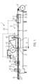
- FIG. 1 shows a schematic side view of an intermittently operating thermoforming packaging machine 1 according to the invention.
- This thermoforming packaging machine 1 has a forming station 2, a sealing station 3, a cross cutting device 4 and a longitudinal cutting device 5, which are arranged in this order in a transport direction R on a machine frame 6.
- a material store 9 is provided in the area of the sealing station 3, from which a top film 10 is drawn off.
- a discharge device 13 in the form of a conveyor belt is provided on the thermoforming packaging machine 1, with which finished, individual packages 14 are transported away.
- thermoforming packaging machine 1 has a feed device, not shown in detail, which grips the lower film 8 and transports it further in the transport direction R per main work cycle.
- the feed device can be implemented, for example, by transport chains or clamping chains arranged on both sides.
- the forming station 2 is designed as a deep-drawing station, in which depressions 15 are formed in the lower film 8 by deep-drawing, for example by means of compressed air and/or vacuum.
- the forming station 2 can be designed in such a way that several troughs 15 are formed next to one another in the direction perpendicular to the transport direction R.
- the sealing station 3 has a hermetically sealable chamber K in which the atmosphere in the troughs 15 can be evacuated prior to sealing with the top film 10, for example, and/or replaced by flushing with a replacement gas or a gas mixture.
- the cross-cutting device 4 is designed as a punch, which cuts through the lower film 8 and the upper film 10 in a direction transverse to the transport direction R between adjacent troughs 15 .
- the cross-cutting device 4 works in such a way that the lower film 8 is not severed over the entire width, but rather is not severed at least in an edge region. This enables controlled onward transport by the feed device.
- the longitudinal cutting device 5 is designed as a knife arrangement with which the lower film 8 and the upper film 10 are severed between adjacent troughs 15 and at the lateral edge of the lower film 8 in the longitudinal direction R, so that individual packages 14 are present behind the longitudinal cutting device 5 .
- the thermoforming packaging machine 1 also has a controller 19. It has the task of controlling and monitoring the processes taking place in the thermoforming packaging machine 1.
- a display device 20 with operating elements 21 serves to visualize or influence the process sequences in the thermoforming packaging machine 1 for or by an operator.
- Central electrical components of the deep-drawing machine 1 are arranged in a control cabinet 22, for example the connection to an external power source.
- the controller 19 exchanges data with the workstations 2, 3, 4, 5 of the thermoforming packaging machine 1 and with the control cabinet 22 via a communication bus 23, hereinafter referred to as the bus for short.
- 4, 5 is provided for connection to the communication bus 23 in each case a bus node arrangement 24.
- the sealing station 3 has a lower part 25 in which one or more packaging troughs 15 can be accommodated, and a bell-shaped upper part 26 with a wall 27 which surrounds an interior space 28 .
- the lower and upper parts 25, 26 can be closed to form the hermetically sealed chamber K together.
- the tool 29 In the interior 28 of the sealing station 3 there is a tool 29 which is a sealing plate here.
- the tool 29 can be a heating plate or a heated mold.
- the tool 29 has at least one heating element 30 with which it can preferably be heated electrically. In 2 three such heating elements 30 embedded in the tool 29 are shown.
- the tool 29 has at least one actuator 30—in the case of a forming station 2, for example, a movable forming die 30, see FIG 1 .
- a bus node arrangement 24 is placed on the outside 31 of the wall 27 facing away from the interior 28 .
- This bus node assembly 24 includes a housing cap 32 which may be molded from plastic material, either translucent or opaque plastic.
- An annular seal 33 made of flexible material seals the housing cap 32 against the outer side 31 of the wall 27 so that it is at least dust-tight and/or splash-proof.
- the ring seal 33 is preferably made of transparent or translucent material; it can, for example, have silicone or consist of silicone.
- a massive and stable support 34 for example made of aluminum.
- the carrier 34 supports a printed circuit board 35 which it carries and which is equipped with electronic components 36 .
- a seal 37 for example in the form of a silicone mat 37 , is arranged between circuit board 35 and carrier 34 .
- the bus node arrangement 24 also has an interface 38 which is connected to the circuit board 35 and by means of which the circuit board 35 is connected to the communication bus 23 .
- Electrical lines 39 connect the circuit board 35 to the respective heating elements 30 and/or actuators 30. These electrical lines 39 provide power for the operation of the heating elements 30 and/or actuators 30.
- the bus node arrangement 24 also has at least one light source 40, e.g. B. in the form of one or more LEDs.
- the light source 40 is arranged on the circuit board 35 and is operated by it.
- the light source 40 can be operated in such a way that the light source 40 is driven to generate different colors (e.g. blue, green, yellow/orange or red), different illuminance levels and/or different lighting patterns over time (e.g. flashing). If more than one light source 40 is provided, these can also be controlled to generate different spatial lighting patterns, for example moving lighting patterns.
- one or more of the light sources can be additionally or alternatively arranged on an edge 41 of the housing cap 32 facing the ring seal 33 . In the exemplary embodiment shown, these light sources 40 are seated in a depression in the edge 41 of the housing cap 32 facing the ring seal 33. Alternatively, the light sources 40 are part of the circuit board 35, which can extend up to the housing cap 32.
- control elements 36a for controlling the at least one heating element or actuator 30 can also be provided on the printed circuit board 35.
- Control elements 36a for the heating elements 30 are understood to mean, for example, contactors or solid-state relays.
- Certain electronic components 36b on circuit board 35 can be configured to receive and/or evaluate signals from one or more sensors 42 provided in workstation 3. These can be, for example, temperature sensors 42 for measuring the temperature of tool 29, pressure sensors 42 for Measuring a pressure in the interior 28 or in the sealing chamber K or a gas sensor 42 for measuring a content of oxygen or another gas.
- a position sensor 42 for detecting a position of the sealing plate could be provided at a sealing station.
- FIG. 2 also shows that there is a recess 43 in the wall 27 of the sealing station 3, which in the present exemplary embodiment even continues to the interior 28.
- the recess 43 is completely covered by the housing cap 32 of the bus node arrangement 24.
- even the carrier 34 is so large that it already completely covers the cutout 34 .
- FIG. 3 shows the bus node arrangement 24 arranged on the outside 31 of the wall 27 of the workstation 3 in a perspective view.
- the heads of six threaded bolts 44 in the present exemplary embodiment can be seen, with which the bus node arrangement 24 or its housing cap 32 is detachably fastened to the outside 31 of the wall 27 .
- the ring seal 33 for sealing the housing cap 32 against the outside 31 of the wall 27 is visible from the outside.
- the ring seal 33 runs around the housing cap 32 and can be illuminated from the inside by means of the light source(s) 40 .
- a data cable 45 is provided for the communication bus 23, which is routed into the bus node arrangement 24 in the area of the interface 38.
- the data cable 45 can be an Ethernet or EtherCAT cable, for example.
- a separate power cable 46 is provided to supply power or power to the bus node arrangement 24 and, via this, to supply power to the heating elements 30 of the tool 29 and is routed parallel to the data cable 45 into the bus node arrangement 24 .
- a hybrid cable 47 is provided, via which both the data exchange via the communication bus 23 and the current or power supply of the bus node arrangement 24 take place.
- the housing cap 32 of the bus node arrangement 24 can also be made more stable, for example as an aluminum die-cast part.
- threaded bolts 44 other means for releasably attaching the housing cap 32 to the wall may be used 27 of the workstation 2, 3, 4, 5 are used, such as clips or brackets.
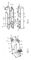
- FIG. 5 shows a perspective view of the bus node arrangement 24.
- the housing 32 is shown, which is detachably fastened to the outside 31 of the wall 27 of the workstation 2, 3, 4, 5 by means of the threaded bolt 44.
- the circuit board 35 which is carried by the carrier 34, becomes visible.
- the bus node arrangement 24 also includes a connector strip 49, which is mechanically connected to the carrier 34, for example, and to which further consumers and/or sensors 42 can be connected.
- two sensors 42 for example pressure sensors or sensors for measuring the concentration of specific gases, are integrated into the bus node arrangement 24. These integrated sensors 42 can be provided in addition to or as an alternative to the sensors 42 arranged in the tool 29, for example.
- the carrier 34 for example made of aluminum, has openings 50 which penetrate the carrier 34 from its side 51 facing the circuit board 35 to the opposite side 52 facing the wall 27 .
- These openings 50 form potting nests into which a potting compound such as polyurethane can be cast during assembly after cables have been routed through or electronic components 36 have been inserted on circuit board 35 .
- the carrier 34 can be connected to the outside 31 of the wall 27 in a fixed but detachable manner by means of a plurality of threaded bolts 53 .
- the seal 37 designed as a silicone mat also has recesses 54 which are essentially congruent with the shape of the openings 50 in the carrier 34 and could even have exactly the same size.
- the bus node arrangement 24 has two different boards 35a, 35b, namely a power board 35a and a logic board 35b.
- a connector or contact arrangement 55 for connection to the connection 48 for the power cable 46 is provided on the power board 35a.
- a plurality of pins 56 support logic board 35b and maintain it at a predetermined spacing relative to power board 35a.
- Electrical contacts or contact pins 57 extend through the seal 37 and the carrier 34 from the circuit boards 35a, 35b.
- the electrical contacts 57 can, for example, be in the form of contact pins made of brass and can optionally be encased in a plastic sleeve 58 .
- the tool 29 used in the work station 2, 3, 4, 5 can have an individual, unique identifier.
- the bus node arrangement 24 is able to read out this identifier of the tool 29 wirelessly or by wire and to make it available to the controller 19 of the thermoforming packaging machine 1 via the bus 23 . This in turn allows the controller 19 to check whether the correct tool 29 is installed. If an incorrect tool 29 is installed, an error message can be output. On the other hand, if a correctly installed tool 29 is recognized, the operation of the thermoforming packaging machine 1 or of the work station 2, 3, 4, 5 can be adapted to the respective tool 29.
- an (RFID) reading head 59 can be connected to the circuit board 35, 35b, for example.
- the bus node arrangement 24 can consequently transmit data relating to the tool 29 to the machine control 19 via the bus 23 . At the same time, it can receive control commands or configuration data from the controller 19 via the bus 23, for example with regard to certain heating or sealing methods, the film width, the deduction length, the format division, the sealing area or the sealing pressure.
- the sensors 42 can be used to monitor the operation of the workstation 2, 3, 4, 5, so that status signals can be transmitted via the bus 23 to the controller 19 of the packaging machine 1, for example with regard to the pressure prevailing in the chamber K, the concentration of certain gases, the sealing pressure used, the prevailing temperature, etc.
- the bus node arrangement 24 also allows the operator of the packaging machine 1 to give feedback on the status and operation of the respective work station 2, 3, 4 due to its shape, which is placed on the outside 31 and protrudes beyond the outside 31, and the at least one light source 40 , 5.
- the light source 40 may glow blue or green when the workstation 2, 3, 4, 5 is operating properly. The operator sees this via the ring seal 33, which is illuminated from the inside—and to a large extent independently of his current location.
- the light source 40 may glow yellow/orange when the operation of the workstation 2, 3, 4, 5 or its tool 29 is becoming problematic or requires inspection by the operator.
- a red light source 40 can signal a blockage or standstill of the workstation.
- the arrangement of the bus node arrangements 24 at or on the respective work stations 2, 3, 4, 5 enables the operator to identify very quickly at which work station the problem has occurred. This minimizes the time required to resolve the problem, which improves the operation of the packaging machine 1. Additionally or alternatively, the warning signal can be flashed of the light source 40 are emphasized. Various embodiments are conceivable here, which the operator of the packaging machine 1 can evaluate by means of corresponding explanations in the operating manual for the packaging machine 1 .
- the bus node arrangement 24 of the present invention offers further advantages in that it enables a watertight and possibly vacuum-tight or pressure-tight cable bushing to the interior 28 of the respective workstations 2, 3, 4, 5. In addition, due to the detachable attachment to the wall 27, the bus node arrangement 24 can be easily serviced and/or replaced.
- bus node arrangement 24 can be combined with one another in any way.
Landscapes
- Engineering & Computer Science (AREA)
- Mechanical Engineering (AREA)
- Physics & Mathematics (AREA)
- Thermal Sciences (AREA)
- Computer Networks & Wireless Communication (AREA)
- Signal Processing (AREA)
- Casings For Electric Apparatus (AREA)
- Package Closures (AREA)
Description
- Die Erfindung bezieht sich auf eine Verpackungsmaschine gemäß dem Oberbegriff des Anspruchs 1.
- Eine Verpackungsmaschine ist aus der
DE 10 2008 024 461 A1 bekannt. Diese Verpackungsmaschine verfügt über verschiedene Bearbeitungsstationen, wie beispielsweise Form-, Siegel- und Schneidstationen, die gemeinsam von einer Zentralsteuereinheit gesteuert werden. Jede einzelne Bearbeitungsstation verfügt über eine individuelle Bearbeitungsstationssteuereinheit, die für die Steuerung eines in der jeweiligen Station vorhandenen Werkzeugs sorgt. - Eine gattungsgemäße Verpackungsmaschine ist in der
EP 1 440 886 A1 beschrieben. - Eine andere Verpackungsmaschine, die mit einem um die gesamte Verpackungsmaschine herumlaufenden Lichtband versehen ist, geht aus der
EP 3 088 314 A1 hervor. - Schließlich offenbart die
DE 100 12 579 B4 eine Bearbeitungsstation mit einem Bussystem, allerdings ohne jeden Bezug zu Verpackungsmaschinen sondern zum Einsatz für eine geschlossene Transportbahn für Paletten. - Die Aufgabe der Erfindung ist es, eine Verpackungsmaschine hinsichtlich der Effizienz ihres Betriebs und ihrer Handhabung weiter zu verbessern.
- Diese Aufgabe wird gelöst durch eine Verpackungsmaschine mit den Merkmalen des Anspruchs 1. Vorteilhafte Weiterbildungen der Erfindung sind in den Unteransprüchen angegeben.
- Die Erfindung bezieht sich auf eine Verpackungsmaschine mit einer Arbeitsstation, die in ihrem Inneren ein Werkzeug mit wenigstens einem Heizelement und/oder einem anderen Aktor aufweist. Bei der Arbeitsstation kann es sich damit um eine Formstation handeln, in deren Innerem als Werkzeug ein Formwerkzeug zum Tiefziehen von Mulden in eine Verpackungsfolie vorgesehen ist. Alternativ könnte es sich bei der Arbeitsstation um eine Siegelstation handeln, die als Werkzeug ein Siegelwerkzeug aufweist, beispielsweise eine beheizte Siegelplatte. Denkbar wäre es auch, dass es sich bei der Arbeitsstation um eine Schneidstation mit einem beheizten Messer als Werkzeug handelt. Das Heizelement kann ein elektrisches Heizelement wie beispielsweise ein Rohrheizkörper oder ein Widerstandsheizelement oder auch ein induktives Heizelement sein. Ein Aktor ist allgemein ein Element, welches als Teil des Werkzeugs auf Verpackungsmaterial einwirkt, z. B. durch Ausüben von Wärme (dazu kann der Aktor beispielsweise ein Ultraschallerzeuger sein) oder durch Ausüben mechanischer Kräfte (dazu kann bei einer Formstation als Arbeitsstation der Aktor beispielsweise ein bewegter Formstempel sein).
- Auf der Außenseite der Arbeitsstation ist erfindungsgemäß eine Busknotenanordnung aufgesetzt. Diese Busknotenanordnung umfasst eine Gehäusekappe, die zum Schutz vor Verschmutzung, Feuchtigkeit und/oder thermischen Einflüssen dient. Die Gehäusekappe überdeckt wenigstens eine mit Elektronikbauteilen bestückte Platine, die ihrerseits mit einer Schnittstelle zum Verbinden mit einem elektronischen Kommunikationsbus verbunden ist. Die Busknotenanordnung ist ferner dazu konfiguriert, über die Schnittstelle eine Information über das Werkzeug der Arbeitsstation bereitzustellen und/oder von außen Steuerungsdaten für das Werkzeug zu empfangen. Bei den Informationen kann es sich beispielsweise um Daten zur konkreten Ausführung des Werkzeugs handeln, während es sich bei den Steuerungsdaten um Arbeitsbefehle oder Sollwerte für den Betrieb des Werkzeugs handeln kann. Bei beiden Arten von Daten kann es sich beispielsweise um eine Abzugslänge der Folienbahn, die Größe einer Siegelfläche, eine Siegeltemperatur, eine Formatbezeichnung des Werkzeugs, ein Werkzeughub oder maximale oder minimale Werte für die vorgenannten Parameter handeln.
- Als Bus oder Kommunikationsbus wird hier in üblicher Weise ein System zur Datenübertragung zwischen mehreren Teilnehmern über einen gemeinsamen Übertragungsweg verstanden. Bei einem Busknoten handelt es sich um eine an den Bus angeschlossene Komponente, allgemein auch als Busteilnehmer bezeichnet. Eine Busknotenanordnung umfasst einen solchen Busknoten.
- Ein technischer Vorteil der Erfindung liegt darin, dass in die Busknotenanordnung als mechatronische Komponente Elektronik ausgelagert wird, die sich bei herkömmlichen Maschinen in einem zentralen Schaltschrank befunden hatte. Dies führt dazu, dass der Platzbedarf für den zentralen Schaltschrank und damit u. U. auch für die gesamte Verpackungsmaschine kleiner wird. Ein weiterer Vorteil liegt darin, dass die Busknotenanordnung bedingt durch ihre Anordnung auf der Außenseite der Wand der Arbeitsstation leicht zugänglich ist, insbesondere um die Busknotenanordnung zu warten oder neu konfigurieren zu können. Zudem kann Verkabelung eingespart werden, was wiederum einen möglichst hygienischen Betrieb der Maschine begünstigt.
- Als besonders vorteilhafte Variante sieht die Busknotenanordung einen Träger für die Platine vor. Bei diesem Träger kann es sich um eine stabile Struktur handeln, die die u. U. empfindliche Platine vor mechanischer Beanspruchung schützt. Vorzugsweise ist der Träger dermaßen formstabil, dass er Druckunterschieden bis zu 6 bar zwischen den der Platine zugewandten und der Platine abgewandten Seiten des Trägers standhält.
- Bevorzugt trennt der Träger eine der Platine zugewandte Seite hermetisch von einer gegenüberliegenden, d. h. der Platine abgewandten Seite. Dies ermöglicht es, die von der Platine abgewandte Seite des Trägers den im Innenraum der Arbeitsstation herrschenden, u. U. wechselnden Druckverhältnissen auszusetzen, ohne dass die Platine diesen Druckunterschieden ausgesetzt wäre.
- In einer zweckmäßigen Ausführung weist der Träger Aluminium als Material auf.
- Zweckmäßig kann es sein, wenn die Busknotenanordnung derart über einer Aussparung in der Wand der Arbeitsstation angeordnet ist, dass die Gehäusekappe und/oder der Träger die Aussparung vollständig überdeckt. Diese Aussparung kann den Zugang zum Innenraum der Arbeitsstation ermöglichen, beispielsweise zu Messzwecken oder um einen Werkzeugwechsel zu vereinfachen. Gleichzeitig schützt die Gehäusekappe nicht nur die in ihr enthaltenen Teile der Busknotenanordnung sondern auch die Aussparung und damit den Innenraum der Arbeitsstation.
- Vorzugsweise ist zwischen dem Träger und der Platine eine Abdichtung vorgesehen, bei der es sich z. B. um eine Silikonmatte handeln kann. Diese Abdichtung verhindert das Hindurchtreten von Staub, Feuchtigkeit oder Nässe zwischen dem Träger und der Platine. Wenn die Abdichtung ein flexibles Material aufweist, sorgt sie außerdem für eine Stoßdämpfung zwischen dem Träger und der Platine.
- Als vorteilhaft stellt es sich heraus, wenn die Gehäusekappe lösbar an der Wand der Arbeitsstation befestigbar ist, z. B. mittels Gewindebolzen. Das Abnehmen der Gehäusekappe kann dann eine Kontrolle oder Neukonfiguration der wenigstens einen Platine der Busknotenanordnung erlauben.
- Erfindungsgemäß ist eine Ringdichtung vorgesehen, die die Gehäusekappe ringförmig umlaufend gegen die Außenseite der Wand abdichtet, vorzugsweise wasserdicht, staubdicht und/oder spritzwasserdicht. Auf diese Weise sind die Busknotenanordnung, insbesondere die Platine und ihre Elektronikbauteile, besonders effektiv geschützt gegenüber negativen Einflüssen im Betrieb und/oder bei der Reinigung der Verpackungsmaschine.
- In einer Variante der Erfindung ist die Ringdichtung insgesamt oder zumindest abschnittsweise transparent oder transluzent. Zu diesem Zweck kann die Ringdichtung beispielsweise aus Silikon gebildet sein.
- Denkbar ist es ferner, dass die Busknotenanordnung eine Lichtquelle aufweist, die beispielsweise in Form von einer oder mehreren Leuchtdioden vorgesehen sein kann. Der Betrieb der wenigstens einen Lichtquelle kann über die Platine der Busknotenanordnung erfolgen.
- Die wenigstens eine Lichtquelle ist zweckmäßig innerhalb der Gehäusekappe oder an einer der Ringdichtung zugewandten Kante der Gehäusekappe angeordnet. Dies bedeutet, dass die Lichtquelle durch die Gehäusekappe und/oder durch die Ringdichtung geschützt ist vor negativen Einflüssen durch Staub, Wasser oder Feuchtigkeit, und dass sie die Gehäusekappe und/oder die Ringdichtung quasi von innen beleuchtet.
- In einem bestimmten erfindungsgemäßen Konzept zum Betrieb der Verpackungsmaschine ist die Lichtquelle ansteuerbar zum Erzeugen unterschiedlicher Farben und/oder unterschiedlicher zeitlicher oder räumlicher Leuchtmuster. Dies ermöglicht es, dass die Busknotenanordnung einem Bediener der Verpackungsmaschine eine optische Statusmeldung gibt betreffend den Betrieb derjenigen Arbeitsstation, an der die jeweilige Busknotenanordnung angebracht ist. Beispielsweise könnte die Lichtquelle in den Farben Blau, Grün, Gelb/Orange oder Rot leuchten, wobei grünes oder blaues Licht einen ordnungsgemäßen Betrieb der Arbeitsstation, gelbes/oranges Licht eine Warnung und rotes Licht eine Fehlermeldung bzw. einen Stillstand der Arbeitsstation signalisiert. Als zeitliches Leuchtmuster mit besonderer Warnwirkung wäre ein Blinken der Lichtquelle denkbar, als räumliches Leuchtmuster ein Hin- und Herlaufen oder ein Umlaufen eines Lichtsignals um die Ringdichtung der Busknotenanordnung herum. Zusätzlich oder alternativ zu einer optischen Informationsvermittlung über die wenigstens eine Lichtquelle wäre auch eine akustische Informationsübermittlung an den Bediener denkbar, beispielsweise über einen Tongenerator.
- Die über die Schnittstelle bereitgestellte Information über das Werkzeug könnte insbesondere eine Kennung des jeweiligen Werkzeugs umfassen, mit der das Werkzeug eindeutig identifizierbar ist. Dies ist vorteilhaft, um beispielweise den Betrieb der Arbeitsstation und damit der gesamten Verpackungsmaschine mit unpassenden Werkzeugen zu verhindern. Nach dem Wechseln eines passenden Werkzeugs kann außerdem der Betrieb der Arbeitsstation und/oder der gesamten Verpackungsmaschine anhand der Kennung auf das jeweilige Werkzeug und seine Eigenschaften abgestimmt werden.
- Bevorzugt ist die Schnittstelle als bidirektionale Schnittstelle ausgebildet, so dass über sie nicht nur Daten oder Informationen von dem Werkzeug nach außen an den Bus ausgegeben werden, sondern auch Steuerungsdaten über die Schnittstelle empfangen und an das Werkzeug weitergeleitet werden können.
- Günstig ist es auch, wenn die Kommunikation über die Schnittstelle verschlüsselt ist, was die Prozesssicherheit der Verpackungsmaschine verbessert.
- An der Platine der Busknotenanordnung können ferner ein oder mehrere insbesondere elektrische oder elektronische Steuerelemente zur Ansteuerung des wenigstens einen Heizelements des Werkzeugs vorgesehen sein, so dass insbesondere für diese Steuerelemente weniger oder gar kein Platz mehr in einem zentralen Schaltschrank der Verpackungsmaschine bereitgehalten werden muss. Bei den Steuerelementen kann es sich um Schütze oder um Solid-State-Relais handeln.
- In einer zweckmäßigen Variante der Erfindung sind in der Arbeitsstation ein oder mehrere Sensoren vorgesehen, die beispielsweise eine Temperatur des Werkzeugs oder der Heizelemente, einen Druck von Aktorik der Arbeitstation oder den Gasdruck in einer Arbeitskammer der Arbeitsstation messen. Bestimmte Elektronikbauteile an der Platine können dann konfiguriert sein zum Empfangen und/oder zum Auswerten von Signalen des einen Sensors oder der mehreren Sensoren.
- Schließlich ist die Busknotenanordnung vorzugsweise für den Anschluss an ein Hybridkabel ausgebildet, über das sowohl eine Leistungsversorgung als auch der Kommunikationsbus mit der Busknotenanordnung gekoppelt werden.
- Im Folgenden wird die Erfindung anhand von Ausführungsbeispielen näher erläuert. Im Einzelnen zeigen:
- Fig. 1
- eine schematische Seitenansicht einer erfindungsgemäßen Verpackungsmaschine,
- Fig. 2
- eine schematische Darstellung einer Arbeitsstation der Verpackungsmaschine,
- Fig. 3
- eine perspektivische Ansicht eines ersten Ausführungsbeispiels einer Busknotenanordnung,
- Fig. 4
- eine perspektivische Ansicht eines zweiten Ausführungsbeispiels einer Busknotenanordnung,
- Fig. 5
- eine weitere perspektivische Ansicht einer Busknotenanordnung und
- Fig. 6
- eine Explosionsdarstellung einer Busknotenanordnung.
- Gleiche Komponenten sind in den Figuren durchgängig mit gleichen Bezugszeichen versehen.
-
Figur 1 zeigt in einer schematischen Seitenansicht eine erfindungsgemäße, intermittierend arbeitende Tiefziehverpackungsmaschine 1. Diese Tiefziehverpackungsmaschine 1 weist eine Formstation 2, eine Siegelstation 3, eine Querschneideeinrichtung 4 und eine Längsschneideeinrichtung 5 auf, die in dieser Reihenfolge in einer Transportrichtung R an einem Maschinengestell 6 angeordnet sind. Eingangsseitig befindet sich an dem Maschinengestell 6 eine Zufuhrrolle 7, von der eine Unterfolie 8 abgezogen wird. Im Bereich der Siegelstation 3 ist ein Materialspeicher 9 vorgesehen, von dem eine Oberfolie 10 abgezogen wird. Ausgangsseitig ist an der Tiefziehverpackungsmaschine 1 eine Abfuhreinrichtung 13 in Form eines Transportbandes vorgesehen, mit der fertige, vereinzelte Verpackungen 14 abtransportiert werden. Ferner weist die Tiefziehverpackungsmaschine 1 eine nicht näher dargestellte Vorschubeinrichtung auf, die die Unterfolie 8 ergreift und diese pro Hauptarbeitstakt in der Transportrichtung R weitertransportiert. Die Vorschubeinrichtung kann zum Beispiel durch beidseitig angeordnete Transportketten bzw. Klammerketten ausgeführt sein. - In der dargestellten Ausführungsform ist die Formstation 2 als eine Tiefziehstation ausgebildet, bei der in die Unterfolie 8 durch Tiefziehen, beispielsweise mittels Druckluft und/oder Vakuum, Mulden 15 geformt werden. Dabei kann die Formstation 2 derart ausgebildet sein, dass in der Richtung senkrecht zur Transportrichtung R mehrere Mulden 15 nebeneinander gebildet werden. In Transportrichtung R hinter der Formstation 2 ist eine Einlegestrecke 16 vorgesehen, in der die in der Unterfolie 8 geformten Mulden 15 mit Produkt 17 befüllt werden.
- Die Siegelstation 3 verfügt über eine hermetisch verschließbare Kammer K, in der die Atmosphäre in den Mulden 15 vor dem Versiegeln mit der Oberfolie 10 zum Beispiel evakuiert und/oder durch Gasspülen mit einem Austauschgas oder mit einem Gasgemisch ersetzt werden kann.
- Die Querschneideeinrichtung 4 ist als Stanze ausgebildet, die die Unterfolie 8 und die Oberfolie 10 in einer Richtung quer zur Transportrichtung R zwischen benachbarten Mulden 15 durchtrennt. Dabei arbeitet die Querschneideeinrichtung 4 derart, dass die Unterfolie 8 nicht über die gesamte Breite aufgetrennt wird, sondern zumindest in einem Randbereich nicht durchtrennt wird. Dies ermöglicht einen kontrollierten Weitertransport durch die Vorschubeinrichtung.
- Die Längsschneideeinrichtung 5 ist in der dargestellten Ausführungsform als eine Messeranordnung ausgebildet, mit der die Unterfolie 8 und die Oberfolie 10 zwischen benachbarten Mulden 15 und am seitlichen Rand der Unterfolie 8 in der Längsrichtung R durchtrennt werden, so dass hinter der Längsschneideeinrichtung 5 vereinzelte Verpackungen 14 vorliegen.
- Die Tiefziehverpackungsmaschine 1 verfügt ferner über eine Steuerung 19. Sie hat die Aufgabe, die in der Tiefziehverpackungsmaschine 1 ablaufenden Prozesse zu steuern und zu überwachen. Eine Anzeigevorrichtung 20 mit Bedienelementen 21 dient zum Visualisieren bzw. Beeinflussen der Prozessabläufe in der Tiefziehverpackungsmaschine 1 für bzw. durch einen Bediener.
- In einem Schaltschrank 22 sind zentrale Elektrikbauteile der Tiefziehmaschine 1 angeordnet, beispielsweise die Verbindung zu einer externen Stromquelle. Über einen Kommunikationsbus 23, im Folgenden kurz Bus genannt, steht die Steuerung 19 in Datenaustausch mit den Arbeitsstationen 2, 3, 4, 5 der Tiefziehverpackungsmaschine 1 und mit dem Schaltschrank 22. An zumindest einer einzigen, vorzugsweise jedoch an mehreren Arbeitsstationen 2, 3, 4, 5 ist zur Anbindung an den Kommunikationsbus 23 jeweils eine Busknotenanordnung 24 vorgesehen.
-
Fig. 2 zeigt schematisch einen Vertikalschnitt durch die Siegelstation 3 als Beispiel für eine Arbeitsstation. Die Siegelstation 3 verfügt über ein Unterteil 25, in dem eine oder mehrere Verpackungsmulden 15 aufnehmbar sind, sowie über ein glockenförmiges Oberteil 26 mit einer Wand 27, die einen Innenraum 28 umgibt. Unter- und Oberteil 25, 26 können geschlossen werden, um gemeinsam die hermetisch abgeschlossene Siegelkammer K zu bilden. - Im Innenraum 28 der Siegelstation 3 ist ein Werkzeug 29 angeordnet, bei dem es sich hier um eine Siegelplatte handelt. Bei einer Formstation 2 als Arbeitsstation kann es sich beim Werkzeug 29 um eine Heizplatte oder um ein beheiztes Formwerkzeug handeln. Das Werkzeug 29 verfügt über wenigstens ein Heizelement 30, mit dem es vorzugsweise elektrisch beheizbar ist. In
Fig. 2 sind drei solcher Heizelemente 30 dargestellt, die in das Werkzeug 29 eingebettet sind. Alternativ oder zusätzlich weist das Werkzeug 29 wenigstens einen Aktor 30 auf - im Falle einer Formstation 2 beispielsweise einen beweglichen Formstempel 30, sieheFig. 1 . - Auf die vom Innenraum 28 abgewandte Außenseite 31 der Wand 27 ist erfindungsgemäß eine Busknotenanordnung 24 aufgesetzt. Diese Busknotenanordnung 24 weist eine Gehäusekappe 32 auf, die aus Kunststoffmaterial geformt sein kann, und zwar entweder aus lichtdurchlässigem oder aus lichtundurchlässigem Kunststoff. Eine Ringdichtung 33 aus flexiblem Material dichtet die Gehäusekappe 32 zumindest staub- und/oder spritzwasserdicht gegen die Außenseite 31 der Wand 27 ab. Die Ringdichtung 33 ist vorzugsweise aus transparentem oder transluzentem Material; sie kann beispielsweise Silikon aufweisen oder aus Silikon bestehen.
- Im Inneren der Gehäusekappe 32 befindet sich ein massiver und stabiler Träger 34, beispielsweise aus Aluminium. Der Träger 34 unterstützt eine von ihm getragene Platine 35, die mit Elektronikbauteilen 36 bestückt ist. Zwischen der Platine 35 und dem Träger 34 ist eine Abdichtung 37, beispielsweise in Form einer Silikonmatte 37, angeordnet.
- Die Busknotenanordnung 24 weist ferner eine mit der Platine 35 verbundene Schnittstelle 38 auf, mittels derer die Platine 35 mit dem Kommunikationsbus 23 verbunden ist. Elektrische Leitungen 39 verbinden die Platine 35 mit den jeweiligen Heizelementen 30 und/oder Aktoren 30. Über diese elektrischen Leitungen 39 wird Strom für den Betrieb der Heizelemente 30 und/oder Aktoren 30 bereitgestellt.
- Die Busknotenanordnung 24 verfügt ferner über wenigstens eine Lichtquelle 40, z. B. in Form einer oder mehrerer LEDs. Im vorliegenden Ausführungsbeispiel ist die Lichtquelle 40 auf der Platine 35 angeordnet und wird von ihr betrieben. Der Betrieb der Lichtquelle 40 kann so erfolgen, dass die Lichtquelle 40 angesteuert wird zum Erzeugen unterschiedlicher Farben (beispielsweise Blau, Grün, Gelb/Orange oder Rot), unterschiedlicher Beleuchtungsstärken und/oder unterschiedlicher zeitlicher Leuchtmuster (beispielsweise blinkend). Wenn mehr als eine Lichtquelle 40 vorgesehen sind, können diese auch angesteuert werden zum Erzeugen verschiedener räumlicher Leuchtmuster, beispielsweise sich bewegender Leuchtmuster. Beispielsweise können zu diesem Zweck eine oder mehrere der Lichtquellen zusätzlich oder alternativ an einer der Ringdichtung 33 zugewandten Kante 41 der Gehäusekappe 32 angeordnet sein. Im dargestellten Ausführungsbeispiel sitzen diese Lichtquellen 40 in einer Vertiefung in der der Ringdichtung 33 zugewandten Kante 41 der Gehäusekappe 32. Alternativ sind die Lichtquellen 40 Teil der Platine 35, die sich bis an die Gehäusekappe 32 erstrecken kann.
- Zusätzlich zu den Elektronikbauteilen 36 können an der Platine 35 auch ein oder mehrere Steuerelemente 36a zur Ansteuerung des wenigstens einen Heizelements oder Aktors 30 vorgesehen sein. Unter Steuerelementen 36a für die Heizelemente 30 werden beispielsweise Schütze oder Solid-State-Relais verstanden. Bestimmte Elektronikbauteile 36b an der Platine 35 können konfiguriert sein zum Empfangen und/oder Auswerten von Signalen von einem oder mehreren in der Arbeitsstation 3 vorgesehenen Sensoren 42. Dabei kann es sich beispielsweise um Temperatursensoren 42 zum Messen der Temperatur des Werkzeugs 29, um Drucksensoren 42 zum Messen eines Drucks im Innenraum 28 bzw. in der Siegelkammer K oder um einen Gassensor 42 zum Messen eines Gehalts an Sauerstoff oder eines anderen Gases handeln. Bei einer Siegelstation könnte ein Positionssensor 42 zum Erfassen einer Position der Siegelplatte vorgesehen sein.
-
Fig. 2 zeigt ferner, dass sich in der Wand 27 der Siegelstation 3 eine Aussparung 43 befindet, die sich im vorliegenden Ausführungsbeispiel sogar fortsetzt bis zum Innenraum 28. Die Aussparung 43 ist vollständig von der Gehäusekappe 32 der Busknotenanordnung 24 überdeckt. Im vorliegenden Ausführungsbeispiel ist sogar der Träger 34 so groß, dass er selbst bereits die Aussparung 34 vollständig überdeckt. -
Fig. 3 zeigt die auf der Außenseite 31 der Wand 27 der Arbeitsstation 3 angeordnete Busknotenanordnung 24 in perspektivischer Ansicht. Zu sehen sind die Köpfe von im vorliegenden Ausführungsbeispiel sechs Gewindebolzen 44, mit denen die Busknotenanordnung 24 bzw. ihre Gehäusekappe 32 lösbar an der Außenseite 31 der Wand 27 befestigt ist. Zu erkennen ist ferner, dass die Ringdichtung 33 zur Abdichtung der Gehäusekappe 32 gegen die Außenseite 31 der Wand 27 von außen sichtbar ist. Die Ringdichtung 33 umläuft die Gehäusekappe 32 und kann mittels der Leuchtquelle(n) 40 von innen beleuchtet werden. - Im Ausführungsbeispiel nach
Fig. 3 ist ein Datenkabel 45 für den Kommunikationsbus 23 vorgesehen, das im Bereich der Schnittstelle 38 in die Busknotenanordnung 24 geführt ist. Beim Datenkabel 45 kann es sich beispielsweise um ein Ethernet- bzw. Ethercat-Kabel handeln. Zusätzlich ist ein separates Stromkabel 46 zur Strom- bzw. Leistungsversorgung der Busknotenanordnung 24 sowie über diese zur Leistungsversorgung der Heizelemente 30 des Werkzeugs 29 vorgesehen und parallel zum Datenkabel 45 in die Busknotenanordung 24 geführt. - Im Ausführungsbeispiel nach
Fig. 4 hingegen ist ein Hybridkabel 47 vorgesehen, über das sowohl der Datenaustausch über den Kommunikationsbus 23 als auch die Strom- bzw. Leistungsversorgung der Busknotenanordnung 24 erfolgt. - Statt aus Kunststoff kann die Gehäusekappe 32 der Busknotenanordnung 24 auch stabiler ausgebildet sein, beispielsweise als Alu-Druckgussteil. Anstelle von Gewindebolzen 44 können auch andere Mittel zum lösbaren Befestigen der Gehäusekappe 32 an der Wand 27 der Arbeitsstation 2, 3, 4, 5 eingesetzt werden, beispielsweise Clips oder Klammern.
-
Fig. 5 zeigt eine perspektivische Ansicht der Busknotenanordnung 24. Dargestellt ist das Gehäuse 32, das mittels der Gewindebolzen 44 an der Außenseite 31 der Wand 27 der Arbeitsstation 2, 3, 4, 5 lösbar befestigt wird. In der teiltransparenten Darstellung der Gehäusekappe 32 wird die Platine 35 sichtbar, die vom Träger 34 getragen wird. An der Außenseite der Gehäusekappe 32 befindet sich ein Anschluss 38 als Schnittstelle zum Kommunikationsbus 23, sowie ein weiterer Anschluss 48 zum Anschließen des Stromkabels 46. - Die elektrischen Leitungen 39 zur Stromversorgung der Heizelemente 30 durchdringen ausgehend von der Platine 35 den Träger 34. Ferner umfasst die Busknotenanordnung 24 in diesem Ausführungsbeispiel eine beispielsweise mit dem Träger 34 mechanisch verbundene Steckerleiste 49, an die weitere Verbraucher und/oder Sensoren 42 anschließbar sind. Im vorliegenden Ausführungsbeispiel sind zwei Sensoren 42, beispielsweise Drucksensoren oder Sensoren zur Messung der Konzentration bestimmter Gase, in die Busknotenanordnung 24 integriert. Diese integrierten Sensoren 42 können zusätzlich oder alternativ zu den beispielweise im Werkzeug 29 angeordneten Sensoren 42 vorgesehen sein.
-
Fig. 6 zeigt ein Ausführungsbeispiel der Busknotenanordnung 24 in Explosionsdarstellung. Zu erkennen ist, dass der Träger 34, beispielsweise aus Aluminium gebildet, Öffnungen 50 aufweist, die den Träger 34 von seiner der Platine 35 zugewandten Seite 51 bis zur gegenüberliegenden, der Wand 27 zugewandten Seite 52 durchdringen. Diese Öffnungen 50 bilden Vergussnester, in die beim Zusammenbau nach dem Hindurchführen von Kabeln oder dem Einsetzen von Elektronikbauteilen 36 an der Platine 35 eine Vergussmasse wie Polyurethan eingegossen werden kann. Mittels mehrerer Gewindebolzen 53 ist der Träger 34 fest, aber lösbar mit der Außenseite 31 der Wand 27 verbindbar. - Die als Silikonmatte ausgebildete Abdichtung 37 weist ebenfalls Aussparungen 54 auf, die im Wesentlichen kongruent sind zur Form der Öffnungen 50 im Träger 34, und sogar genau die gleiche Größe haben könnten.
- Im vorliegenden Ausführungsbeispiel verfügt die Busknotenanordnung 24 über zwei verschiedene Platinen 35a, 35b, nämlich über eine Leistungsplatine 35a und eine Logikplatine 35b. Auf der Leistungsplatine 35a ist eine Stecker- oder Kontaktanordnung 55 zur Anbindung an den Anschluss 48 für das Stromkabel 46 vorgesehen. Eine Mehrzahl von Stiften 56 trägt die Logikplatine 35b und hält sie in einem vorbestimmten Abstand relativ zur Leistungsplatine 35a. Elektrische Kontakte oder Kontaktstifte 57 erstrecken sich ausgehend von den Platinen 35a, 35b durch die Abdichtung 37 und den Träger 34 hindurch. Die elektrischen Kontakte 57 können beispielsweise als Kontaktstifte aus Messing ausgebildet sein und optional von einer Kunststoffhülse 58 umhüllt sein.
- Das in der Arbeitsstation 2, 3, 4, 5 eingesetzte Werkzeug 29 kann über eine individuelle, eindeutige Kennung verfügen. Die Busknotenanordnung 24 ist in der Lage, drahtlos oder drahtgebunden diese Kennung des Werkzeugs 29 auszulesen und sie über den Bus 23 der Steuerung 19 der Tiefziehverpackungsmaschine 1 zur Verfügung zu stellen. Dies wiederum erlaubt der Steuerung 19 eine Überprüfung dahingehend, ob das korrekte Werkzeug 29 eingebaut ist. Bei Einbau eines falschen Werkzeugs 29 kann eine Fehlermeldung ausgegeben werden. Bei Erkennen eines korrekt eingebauten Werkzeugs 29 hingegen kann der Betrieb der Tiefziehverpackungsmaschine 1 bzw. der Arbeitsstation 2, 3, 4, 5 an das jeweilige Werkzeug 29 angepasst werden. Zum Auslesen der Kennung des Werkzeugs 29 kann beispielsweise ein (RFID-)Lesekopf 59 mit der Platine 35, 35b verbunden sein.
- Über den Bus 23 kann die Busknotenanordnung 24 folglich Daten bezüglich des Werkzeugs 29 an die Maschinensteuerung 19 übermitteln. Gleichzeitig kann sie über den Bus 23 Steuerbefehle oder Konfigurationsdaten von der Steuerung 19 empfangen, beispielsweise hinsichtlich bestimmter Heiz- oder Siegelverfahren, der Folienbreite, der Abzugslänge, der Formataufteilung, der Siegelfläche oder des Siegeldrucks.
- Mittels der Sensoren 42 kann der Betrieb der Arbeitsstation 2, 3, 4, 5 überwacht werden, so dass Zustandssignale über den Bus 23 an die Steuerung 19 der Verpackungsmaschine 1 übermittelt werden können, beispielsweise hinsichtlich des in der Kammer K herrschenden Drucks, der Konzentration bestimmter Gase, des verwendeten Siegeldrucks, der herrschenden Temperatur etc.
- Die Busknotenanordnung 24 erlaubt es außerdem, durch ihre auf die Außenseite 31 aufgesetzte und über die Außenseite 31 hinaus vorstehende Form und die mindestens eine Lichtquelle 40, dem Bediener der Verpackungsmaschine 1 Rückmeldung zu geben über den Status und Betrieb der jeweiligen Arbeitsstation 2, 3, 4, 5. Beispielsweise kann die Lichtquelle 40 in blauer oder grüner Farbe leuchten, wenn die Arbeitsstation 2, 3, 4, 5 ordnungsgemäß arbeitet. Der Bediener sieht dies über die von innen beleuchtete Ringdichtung 33 - und zwar weitgehend unabhängig von seinem aktuellen Standort. Die Lichtquelle 40 kann gelb/orange leuchten, wenn der Betrieb der Arbeitsstation 2, 3, 4, 5 oder ihres Werkzeugs 29 problematisch zu werden droht oder eine Inspektion durch den Bediener erfordert. Eine rot leuchtende Lichtquelle 40 kann hingegen eine Blockade oder einen Stillstand der Arbeitsstation signalisieren. Die Anordnung der Busknotenanordnungen 24 an oder auf den jeweiligen Arbeitsstationen 2, 3, 4, 5 ermöglicht es dem Bediener, sehr schnell zu erkennen, an welcher Arbeitsstation das Problem aufgetreten ist. Dies minimiert die zum Beheben des Problems erforderliche Zeit, was den Betrieb der Verpackungsmaschine 1 verbessert. Zusätzlich oder alternativ kann das Warnsignal durch ein Blinken der Lichtquelle 40 betont werden. Hier sind verschiedene Ausführungsformen denkbar, die der Bediener der Verpackungsmaschine 1 mittels entsprechender Erläuterungen im Betriebshandbuch der Verpackungsmaschine 1 auswerten kann.
- Weitere Vorteile bietet die Busknotenanordnung 24 der vorliegenden Erfindung dadurch, dass sie eine wasserdichte und ggf. vakuum- bzw. druckdichte Kabeldurchführung zum Innenraum 28 der jeweiligen Arbeitsstationen 2, 3, 4, 5 ermöglicht. Außerdem kann die Busknotenanordnung 24 bedingt durch die lösbare Befestigung an der Wand 27 leicht gewartet und/oder ersetzt werden.
- Ausgehend von den dargestellten Ausführungsbeispielen sind diverse Änderungen denkbar, ohne vom Schutzumfang der Erfindung abzuweichen. Die beschriebenen Komponenten und Elemente der Busknotenanordnung 24 können in beliebiger Weise miteinander kombiniert werden.
Claims (15)
- Verpackungsmaschine (1) mit einer Arbeitsstation (2, 2a, 3, 4, 5), die einen von einer Wand (27) umgebenen Innenraum (28) aufweist, in welchem ein Werkzeug (29) mit wenigstens einem Heizelement (30) und/oder wenigstens einem Aktor (30) angeordnet ist, wobei eine Busknotenanordnung (24) dazu konfiguriert ist, über eine Schnittstelle (38) eine Information über das Werkzeug (29) bereitzustellen und/oder Steuerungsdaten für das Werkzeug (29) zu empfangen, dadurch gekennzeichnet, dass die Busknotenanordnung (24) auf die vom Innenraum (28) abgewandte Außenseite (31) der Wand (27) aufgesetzt ist und Folgendes umfasst:- eine Gehäusekappe (32),- wenigstens eine mit Elektronikbauteilen (36) bestückte Platine (35), und- die mit der wenigstens einen Platine (35) verbundene Schnittstelle (38) zum Verbinden mit einem Kommunikationsbus (23),wobei eine Ringdichtung (33) vorgesehen ist, die die Gehäusekappe (32) ringförmig umlaufend gegen die Außenseite (31) der Wand (27) abdichtet.
- Verpackungsmaschine nach Anspruch 1, dadurch gekennzeichnet, dass die Busknotenanordnung (24) einen Träger (34) für die Platine (35) aufweist, wobei vorzugsweise der Träger (34) eine der Platine (35) zugewandte Seite (51) des Trägers (34) hermetisch trennt von einer der Platine (35) abgewandten Seite (52) des Trägers (34).
- Verpackungsmaschine nach Anspruch 2, dadurch gekennzeichnet, dass der Träger (34) Aluminium aufweist.
- Verpackungsmaschine nach einem der Ansprüche 2 oder 3, dadurch gekennzeichnet, dass die Busknotenanordnung (24) derart über einer Aussparung (43) in der Wand (27) angeordnet ist, dass die Gehäusekappe (32) die Aussparung (43) vollständig überdeckt.
- Verpackungsmaschine nach einem der Ansprüche 2 bis 4, dadurch gekennzeichnet, dass eine Abdichtung (37) zwischen dem Träger (34) und der Platine (35) vorgesehen ist, vorzugsweise eine Silikonmatte (37).
- Verpackungsmaschine nach einem der vorangehenden Ansprüche, dadurch gekennzeichnet, dass die Gehäusekappe (32) lösbar an der Wand (27) befestigbar ist, vorzugsweise mittels Gewindebolzen (44).
- Verpackungsmaschine nach einem der vorangehenden Ansprüche, dadurch gekennzeichnet, dass die Ringdichtung (33) transparent oder transluzent ist.
- Verpackungsmaschine nach einem der einem der vorangehenden Ansprüche, dadurch gekennzeichnet, dass die Busknotenanordnung (24) wenigstens eine Lichtquelle (40) aufweist.
- Verpackungsmaschine nach den Ansprüchen 7 und 8, dadurch gekennzeichnet, dass die wenigstens eine Lichtquelle (40) innerhalb der Gehäusekappe (32) oder an einer der Ringdichtung (33) zugewandten Kante (41) der Gehäusekappe (32) angeordnet ist.
- Verpackungsmaschine nach einem der Ansprüche 8 oder 9, dadurch gekennzeichnet, dass die Lichtquelle (40) ansteuerbar ist zum Erzeugen unterschiedlicher Farben, unterschiedlicher Beleuchtungsstärken und/oder unterschiedlicher zeitlicher oder räumlicher Leuchtmuster.
- Verpackungsmaschine nach einem der vorangehenden Ansprüche, dadurch gekennzeichnet, dass die über die Schnittstelle (38) bereitgestellte Information über das Werkzeug (29) eine Kennung des Werkzeugs (29) umfasst.
- Verpackungsmaschine nach einem der vorangehenden Ansprüche, dadurch gekennzeichnet, dass die Schnittstelle (38) eine bidirektionale Schnittstelle (38) ist und/oder dass die Kommunikation über die Schnittstelle (38) verschlüsselt ist.
- Verpackungsmaschine nach einem der vorangehenden Ansprüche, dadurch gekennzeichnet, dass an der Platine (35) ein oder mehrere Steuerelemente (36a) zur Ansteuerung des wenigstens einen Heizelements oder Aktors (30) vorgesehen sind.
- Verpackungsmaschine nach einem der vorangehenden Ansprüche, dadurch gekennzeichnet, dass Elektronikbauteile (36b) an der Platine (35) konfiguriert sind zum Empfangen und/oder Auswerten von Signalen von einem oder mehreren in der Arbeitsstation (3) vorgesehenen Sensoren (42).
- Verpackungsmaschine nach einem der vorangehenden Ansprüche, dadurch gekennzeichnet, dass an die Busknotenanordnung (24) ein Hybridkabel (47) anschließbar ist.
Applications Claiming Priority (2)
| Application Number | Priority Date | Filing Date | Title |
|---|---|---|---|
| DE102016125132.1A DE102016125132A1 (de) | 2016-12-21 | 2016-12-21 | Verpackungsmaschine mit Busknotenanordnung |
| PCT/EP2017/072073 WO2018114064A1 (de) | 2016-12-21 | 2017-09-04 | Verpackungsmaschine mit busknotenanordnung |
Publications (3)
| Publication Number | Publication Date |
|---|---|
| EP3560149A1 EP3560149A1 (de) | 2019-10-30 |
| EP3560149B1 EP3560149B1 (de) | 2021-01-13 |
| EP3560149B2 true EP3560149B2 (de) | 2023-08-09 |
Family
ID=59811308
Family Applications (1)
| Application Number | Title | Priority Date | Filing Date |
|---|---|---|---|
| EP17764366.5A Active EP3560149B2 (de) | 2016-12-21 | 2017-09-04 | Verpackungsmaschine mit busknotenanordnung |
Country Status (6)
| Country | Link |
|---|---|
| US (1) | US11418359B2 (de) |
| EP (1) | EP3560149B2 (de) |
| CN (1) | CN210867747U (de) |
| DE (1) | DE102016125132A1 (de) |
| ES (1) | ES2856972T5 (de) |
| WO (1) | WO2018114064A1 (de) |
Families Citing this family (9)
| Publication number | Priority date | Publication date | Assignee | Title |
|---|---|---|---|---|
| DE202016002735U1 (de) | 2016-04-27 | 2016-06-02 | Entrhal Medical Gmbh | Siegelgerät mit Wechseleinheit |
| EP3774551A1 (de) * | 2018-04-10 | 2021-02-17 | GEA Food Solutions Germany GmbH | Eingehauste linie zum bearbeiten und verpacken von lebensmitteln |
| DE102019202755A1 (de) * | 2019-02-28 | 2020-09-03 | Multivac Sepp Haggenmüller Se & Co. Kg | Verfahren zum Betreiben einer Verpackungsmaschine |
| DE102019214965A1 (de) * | 2019-09-30 | 2021-04-01 | Multivac Sepp Haggenmüller Se & Co. Kg | Tiefziehverpackungsmaschine |
| DE102019214962A1 (de) * | 2019-09-30 | 2021-04-01 | Multivac Sepp Haggenmüller Se & Co. Kg | Tiefziehverpackungsmaschine mit Schutzabdeckung |
| CN112623296B (zh) * | 2020-12-21 | 2022-10-28 | 广州铂海科技有限公司 | 一种新型水溶膜全自动包装机 |
| DE102021124794A1 (de) * | 2021-09-24 | 2023-03-30 | Ampack Gmbh | Siegelungsvorrichtung, Siegelungsstation und Verfahren zu einem Betrieb einer Siegelungsvorrichtung |
| DE102022122909B3 (de) | 2022-09-09 | 2023-09-21 | Multivac Sepp Haggenmüller Se & Co. Kg | Lebensmittelverarbeitungsmaschine und Verfahren zum Einschränken von durch einen Bediener an einer Lebensmittelverarbeitungsmaschine aktivierbaren Prozessen |
| DE102024112761B3 (de) * | 2024-05-07 | 2025-05-08 | Strothmann Machines & Handling GmbH | Antriebsvorrichtung und Verfahren zur Beförderung zumindest eines Wagens entlang einer Förderbahn |
Citations (10)
| Publication number | Priority date | Publication date | Assignee | Title |
|---|---|---|---|---|
| DE10012579A1 (de) † | 2000-03-15 | 2001-09-27 | Teamtechnik Maschinen Und Anla | Prozeßmodul für eine Bearbeitungsstation, Bearbeitungsstation und Verfahren zur Inbetriebnahme einer Bearbeitungsstation |
| EP1440886A1 (de) † | 2003-01-23 | 2004-07-28 | TOPACK Verpackungstechnik GmbH | Maschine der tabakverarbeitenden Industrie |
| EP1460502A2 (de) † | 2003-03-21 | 2004-09-22 | Focke & Co. (GmbH & Co.) | Verfahren zum Betrieb einer Steuerung an einem Kommunikationsmedium |
| DE202007007411U1 (de) † | 2007-05-24 | 2007-08-02 | ABL SURSUM Bayerische Elektrozubehör GmbH & Co. KG | Steuerungsgehäuse aus Plattenmaterial |
| DE102008024461A1 (de) † | 2008-05-21 | 2009-12-10 | Multivac Sepp Haggenmüller Gmbh & Co. Kg | Verpackungsmaschine mit einer Bearbeitungsstationssteuereinheit |
| EP2522581A1 (de) † | 2011-05-10 | 2012-11-14 | MULTIVAC Sepp Haggenmüller GmbH & Co KG | Arbeitsstation für eine Verpackungsmaschine und Verfahren zum Werkzeugwechsel |
| EP2860119A1 (de) † | 2013-10-09 | 2015-04-15 | Multivac Sepp Haggenmüller GmbH & Co. KG | Tiefziehverpackungsmaschine und Verfahren |
| EP2889229A1 (de) † | 2013-12-31 | 2015-07-01 | Sidel S.p.a. Con Socio Unico | Maschine zum Bearbeiten von Behältern mit verbesserter Kontrollarchitektur |
| WO2015200911A1 (en) † | 2014-06-27 | 2015-12-30 | Pregis Innovative Packaging Llc | Self-contained computational device for protective packaging systems |
| EP3088314A1 (de) † | 2015-04-30 | 2016-11-02 | J+P Maschinenbau GmbH | Verpackungsmaschine mit zumindest einem teilweisen gehäuse und lichteffekten am gehäuse für hinweise für das bedienpersonal |
Family Cites Families (7)
| Publication number | Priority date | Publication date | Assignee | Title |
|---|---|---|---|---|
| US6678740B1 (en) * | 2000-01-14 | 2004-01-13 | Terayon Communication Systems, Inc. | Process carried out by a gateway in a home network to receive video-on-demand and other requested programs and services |
| DE102007061116A1 (de) * | 2007-12-19 | 2009-06-25 | Robert Bosch Gmbh | Steuergerätegehäuse |
| US9266721B2 (en) * | 2010-11-23 | 2016-02-23 | Robert Bosch Gmbh | Eutectic bonding of thin chips on a carrier substrate |
| KR101920439B1 (ko) * | 2011-04-28 | 2019-02-14 | 삼성전자주식회사 | 공용 인터페이스를 통해 수신 제한 모듈로 암호화된 데이터를 전송하기 위한 데이터 전송 장치 및 그에 적용되는 방법, 수신 제한 모듈 그리고 시스템. |
| DE102011088495A1 (de) * | 2011-12-14 | 2013-06-20 | Endress + Hauser Flowtec Ag | Gehäusedeckel für ein Elektronik-Gehäuse bzw. damit gebildetes Elektronik-Gehäuse |
| JP2014078467A (ja) * | 2012-10-12 | 2014-05-01 | Panasonic Corp | 照明器具、照明装置および発光モジュール |
| US9470864B1 (en) * | 2015-09-01 | 2016-10-18 | Aquaoptics Corp. | Photoelectric conversion module |
-
2016
- 2016-12-21 DE DE102016125132.1A patent/DE102016125132A1/de not_active Withdrawn
-
2017
- 2017-09-04 WO PCT/EP2017/072073 patent/WO2018114064A1/de not_active Ceased
- 2017-09-04 ES ES17764366T patent/ES2856972T5/es active Active
- 2017-09-04 US US16/472,474 patent/US11418359B2/en active Active
- 2017-09-04 CN CN201790001529.2U patent/CN210867747U/zh active Active
- 2017-09-04 EP EP17764366.5A patent/EP3560149B2/de active Active
Patent Citations (10)
| Publication number | Priority date | Publication date | Assignee | Title |
|---|---|---|---|---|
| DE10012579A1 (de) † | 2000-03-15 | 2001-09-27 | Teamtechnik Maschinen Und Anla | Prozeßmodul für eine Bearbeitungsstation, Bearbeitungsstation und Verfahren zur Inbetriebnahme einer Bearbeitungsstation |
| EP1440886A1 (de) † | 2003-01-23 | 2004-07-28 | TOPACK Verpackungstechnik GmbH | Maschine der tabakverarbeitenden Industrie |
| EP1460502A2 (de) † | 2003-03-21 | 2004-09-22 | Focke & Co. (GmbH & Co.) | Verfahren zum Betrieb einer Steuerung an einem Kommunikationsmedium |
| DE202007007411U1 (de) † | 2007-05-24 | 2007-08-02 | ABL SURSUM Bayerische Elektrozubehör GmbH & Co. KG | Steuerungsgehäuse aus Plattenmaterial |
| DE102008024461A1 (de) † | 2008-05-21 | 2009-12-10 | Multivac Sepp Haggenmüller Gmbh & Co. Kg | Verpackungsmaschine mit einer Bearbeitungsstationssteuereinheit |
| EP2522581A1 (de) † | 2011-05-10 | 2012-11-14 | MULTIVAC Sepp Haggenmüller GmbH & Co KG | Arbeitsstation für eine Verpackungsmaschine und Verfahren zum Werkzeugwechsel |
| EP2860119A1 (de) † | 2013-10-09 | 2015-04-15 | Multivac Sepp Haggenmüller GmbH & Co. KG | Tiefziehverpackungsmaschine und Verfahren |
| EP2889229A1 (de) † | 2013-12-31 | 2015-07-01 | Sidel S.p.a. Con Socio Unico | Maschine zum Bearbeiten von Behältern mit verbesserter Kontrollarchitektur |
| WO2015200911A1 (en) † | 2014-06-27 | 2015-12-30 | Pregis Innovative Packaging Llc | Self-contained computational device for protective packaging systems |
| EP3088314A1 (de) † | 2015-04-30 | 2016-11-02 | J+P Maschinenbau GmbH | Verpackungsmaschine mit zumindest einem teilweisen gehäuse und lichteffekten am gehäuse für hinweise für das bedienpersonal |
Also Published As
| Publication number | Publication date |
|---|---|
| DE102016125132A1 (de) | 2018-06-21 |
| US11418359B2 (en) | 2022-08-16 |
| EP3560149A1 (de) | 2019-10-30 |
| WO2018114064A1 (de) | 2018-06-28 |
| US20200136856A1 (en) | 2020-04-30 |
| CN210867747U (zh) | 2020-06-26 |
| EP3560149B1 (de) | 2021-01-13 |
| ES2856972T3 (es) | 2021-09-28 |
| ES2856972T5 (es) | 2023-12-27 |
Similar Documents
| Publication | Publication Date | Title |
|---|---|---|
| EP3560149B2 (de) | Verpackungsmaschine mit busknotenanordnung | |
| EP0323579B1 (de) | Dezentrale Ein/Ausgabebaugruppe für elektronische Steuerungen | |
| DE10327980B4 (de) | Verteilerventil mit Sensoren | |
| EP2578353B1 (de) | Montagearbeitsplatz | |
| EP1183472B1 (de) | Elektronikteil, insbesondere für eine mit ventilen ausgestattete steuereinrichtung | |
| EP1013940B1 (de) | Ventilanordnung | |
| DE1564334B2 (de) | Kontaktstreifen zur Verwendung bei der Serienfertigung von mittels Kunststoffumpressen gekapselten Halbleiterbauelementen | |
| DE102017123821A1 (de) | Anzeige- und/oder Bedienmodul | |
| EP3192618B1 (de) | Verfahren zum betreiben einer pneumatisch angetriebenen anlage zur handhabung von werkstücken sowie anlage zur handhabung von werkstücken | |
| EP2064451B1 (de) | Fluidtechnisches gerät mit lichtleiter | |
| DE202015000059U1 (de) | Verarbeitungsanlage und Kabelkanal einer Verarbeitungsanlage | |
| DE102023107648A1 (de) | Ventilanordnung und Verfahren zur Installation einer Ventilanordnung | |
| DE202019005762U1 (de) | Spannvorrichtung | |
| EP2716578B1 (de) | Verfahren zum Steuern | |
| EP0629783A1 (de) | Kombinierte Steuerung von Pneumatik- und Hydraulikventilen | |
| EP4418056B1 (de) | Bedieneinheit und verfahren zum bedienen einer anlage mit einer bedieneinheit | |
| EP3107211B1 (de) | Steuer- und bedieneinheit für eine hubarbeitsbühne, eine mobile arbeitsmaschine oder eine baumaschine | |
| EP2746593A1 (de) | Ventilanordnung | |
| EP0624831B1 (de) | Steuereinrichtung zur Verwendung im Zusammenhang mit fluidbetätigbaren Einrichtungen | |
| EP2746598B1 (de) | Ventilanordnung | |
| DE102014100271A1 (de) | Verpackungsmaschine mit zumindest einem teilweisen Gehäuse und Lichteffekten am Gehäuse für Hinweise für das Bedienungspersonal | |
| EP1092498B1 (de) | Vorrichtung und Verfahren zur Montage von biegeschlaffen Montageteilen | |
| EP1316388A2 (de) | Zentralkammer | |
| EP4549082A1 (de) | Spannsystem umfassend eine spannvorrichtung und eine konsole | |
| DE202023102397U1 (de) | Signalvorrichtung |
Legal Events
| Date | Code | Title | Description |
|---|---|---|---|
| STAA | Information on the status of an ep patent application or granted ep patent |
Free format text: STATUS: UNKNOWN |
|
| STAA | Information on the status of an ep patent application or granted ep patent |
Free format text: STATUS: THE INTERNATIONAL PUBLICATION HAS BEEN MADE |
|
| PUAI | Public reference made under article 153(3) epc to a published international application that has entered the european phase |
Free format text: ORIGINAL CODE: 0009012 |
|
| STAA | Information on the status of an ep patent application or granted ep patent |
Free format text: STATUS: REQUEST FOR EXAMINATION WAS MADE |
|
| 17P | Request for examination filed |
Effective date: 20190520 |
|
| AK | Designated contracting states |
Kind code of ref document: A1 Designated state(s): AL AT BE BG CH CY CZ DE DK EE ES FI FR GB GR HR HU IE IS IT LI LT LU LV MC MK MT NL NO PL PT RO RS SE SI SK SM TR |
|
| AX | Request for extension of the european patent |
Extension state: BA ME |
|
| DAV | Request for validation of the european patent (deleted) | ||
| DAX | Request for extension of the european patent (deleted) | ||
| GRAP | Despatch of communication of intention to grant a patent |
Free format text: ORIGINAL CODE: EPIDOSNIGR1 |
|
| STAA | Information on the status of an ep patent application or granted ep patent |
Free format text: STATUS: GRANT OF PATENT IS INTENDED |
|
| INTG | Intention to grant announced |
Effective date: 20200731 |
|
| RIN1 | Information on inventor provided before grant (corrected) |
Inventor name: KURZ, ANDREAS Inventor name: REMMELE, THORSTEN Inventor name: FELCH, FLORIAN, Inventor name: LAU, CHRISTIAN Inventor name: RAEDLER, MICHAEL Inventor name: PFALZER, THOMAS Inventor name: EHRMANN, ELMAR Inventor name: BOTZENHARDT, CLAUS |
|
| GRAS | Grant fee paid |
Free format text: ORIGINAL CODE: EPIDOSNIGR3 |
|
| GRAA | (expected) grant |
Free format text: ORIGINAL CODE: 0009210 |
|
| STAA | Information on the status of an ep patent application or granted ep patent |
Free format text: STATUS: THE PATENT HAS BEEN GRANTED |
|
| AK | Designated contracting states |
Kind code of ref document: B1 Designated state(s): AL AT BE BG CH CY CZ DE DK EE ES FI FR GB GR HR HU IE IS IT LI LT LU LV MC MK MT NL NO PL PT RO RS SE SI SK SM TR |
|
| REG | Reference to a national code |
Ref country code: GB Ref legal event code: FG4D Free format text: NOT ENGLISH |
|
| REG | Reference to a national code |
Ref country code: CH Ref legal event code: EP |
|
| REG | Reference to a national code |
Ref country code: CH Ref legal event code: NV Representative=s name: BOVARD AG PATENT- UND MARKENANWAELTE, CH |
|
| REG | Reference to a national code |
Ref country code: IE Ref legal event code: FG4D Free format text: LANGUAGE OF EP DOCUMENT: GERMAN |
|
| REG | Reference to a national code |
Ref country code: DE Ref legal event code: R096 Ref document number: 502017009071 Country of ref document: DE |
|
| REG | Reference to a national code |
Ref country code: AT Ref legal event code: REF Ref document number: 1355363 Country of ref document: AT Kind code of ref document: T Effective date: 20210215 |
|
| REG | Reference to a national code |
Ref country code: NL Ref legal event code: FP |
|
| REG | Reference to a national code |
Ref country code: LT Ref legal event code: MG9D |
|
| PG25 | Lapsed in a contracting state [announced via postgrant information from national office to epo] |
Ref country code: BG Free format text: LAPSE BECAUSE OF FAILURE TO SUBMIT A TRANSLATION OF THE DESCRIPTION OR TO PAY THE FEE WITHIN THE PRESCRIBED TIME-LIMIT Effective date: 20210413 Ref country code: LT Free format text: LAPSE BECAUSE OF FAILURE TO SUBMIT A TRANSLATION OF THE DESCRIPTION OR TO PAY THE FEE WITHIN THE PRESCRIBED TIME-LIMIT Effective date: 20210113 Ref country code: HR Free format text: LAPSE BECAUSE OF FAILURE TO SUBMIT A TRANSLATION OF THE DESCRIPTION OR TO PAY THE FEE WITHIN THE PRESCRIBED TIME-LIMIT Effective date: 20210113 Ref country code: FI Free format text: LAPSE BECAUSE OF FAILURE TO SUBMIT A TRANSLATION OF THE DESCRIPTION OR TO PAY THE FEE WITHIN THE PRESCRIBED TIME-LIMIT Effective date: 20210113 Ref country code: GR Free format text: LAPSE BECAUSE OF FAILURE TO SUBMIT A TRANSLATION OF THE DESCRIPTION OR TO PAY THE FEE WITHIN THE PRESCRIBED TIME-LIMIT Effective date: 20210414 Ref country code: PT Free format text: LAPSE BECAUSE OF FAILURE TO SUBMIT A TRANSLATION OF THE DESCRIPTION OR TO PAY THE FEE WITHIN THE PRESCRIBED TIME-LIMIT Effective date: 20210513 Ref country code: NO Free format text: LAPSE BECAUSE OF FAILURE TO SUBMIT A TRANSLATION OF THE DESCRIPTION OR TO PAY THE FEE WITHIN THE PRESCRIBED TIME-LIMIT Effective date: 20210413 |
|
| PG25 | Lapsed in a contracting state [announced via postgrant information from national office to epo] |
Ref country code: LV Free format text: LAPSE BECAUSE OF FAILURE TO SUBMIT A TRANSLATION OF THE DESCRIPTION OR TO PAY THE FEE WITHIN THE PRESCRIBED TIME-LIMIT Effective date: 20210113 Ref country code: PL Free format text: LAPSE BECAUSE OF FAILURE TO SUBMIT A TRANSLATION OF THE DESCRIPTION OR TO PAY THE FEE WITHIN THE PRESCRIBED TIME-LIMIT Effective date: 20210113 Ref country code: RS Free format text: LAPSE BECAUSE OF FAILURE TO SUBMIT A TRANSLATION OF THE DESCRIPTION OR TO PAY THE FEE WITHIN THE PRESCRIBED TIME-LIMIT Effective date: 20210113 Ref country code: SE Free format text: LAPSE BECAUSE OF FAILURE TO SUBMIT A TRANSLATION OF THE DESCRIPTION OR TO PAY THE FEE WITHIN THE PRESCRIBED TIME-LIMIT Effective date: 20210113 |
|
| REG | Reference to a national code |
Ref country code: ES Ref legal event code: FG2A Ref document number: 2856972 Country of ref document: ES Kind code of ref document: T3 Effective date: 20210928 |
|
| PG25 | Lapsed in a contracting state [announced via postgrant information from national office to epo] |
Ref country code: IS Free format text: LAPSE BECAUSE OF FAILURE TO SUBMIT A TRANSLATION OF THE DESCRIPTION OR TO PAY THE FEE WITHIN THE PRESCRIBED TIME-LIMIT Effective date: 20210513 |
|
| REG | Reference to a national code |
Ref country code: DE Ref legal event code: R026 Ref document number: 502017009071 Country of ref document: DE |
|
| PLBI | Opposition filed |
Free format text: ORIGINAL CODE: 0009260 |
|
| PLAX | Notice of opposition and request to file observation + time limit sent |
Free format text: ORIGINAL CODE: EPIDOSNOBS2 |
|
| PG25 | Lapsed in a contracting state [announced via postgrant information from national office to epo] |
Ref country code: EE Free format text: LAPSE BECAUSE OF FAILURE TO SUBMIT A TRANSLATION OF THE DESCRIPTION OR TO PAY THE FEE WITHIN THE PRESCRIBED TIME-LIMIT Effective date: 20210113 Ref country code: CZ Free format text: LAPSE BECAUSE OF FAILURE TO SUBMIT A TRANSLATION OF THE DESCRIPTION OR TO PAY THE FEE WITHIN THE PRESCRIBED TIME-LIMIT Effective date: 20210113 Ref country code: SM Free format text: LAPSE BECAUSE OF FAILURE TO SUBMIT A TRANSLATION OF THE DESCRIPTION OR TO PAY THE FEE WITHIN THE PRESCRIBED TIME-LIMIT Effective date: 20210113 |
|
| 26 | Opposition filed |
Opponent name: GEA FOOD SOLUTIONS GERMANY GMBH Effective date: 20211008 |
|
| PG25 | Lapsed in a contracting state [announced via postgrant information from national office to epo] |
Ref country code: RO Free format text: LAPSE BECAUSE OF FAILURE TO SUBMIT A TRANSLATION OF THE DESCRIPTION OR TO PAY THE FEE WITHIN THE PRESCRIBED TIME-LIMIT Effective date: 20210113 Ref country code: DK Free format text: LAPSE BECAUSE OF FAILURE TO SUBMIT A TRANSLATION OF THE DESCRIPTION OR TO PAY THE FEE WITHIN THE PRESCRIBED TIME-LIMIT Effective date: 20210113 Ref country code: SK Free format text: LAPSE BECAUSE OF FAILURE TO SUBMIT A TRANSLATION OF THE DESCRIPTION OR TO PAY THE FEE WITHIN THE PRESCRIBED TIME-LIMIT Effective date: 20210113 |
|
| PG25 | Lapsed in a contracting state [announced via postgrant information from national office to epo] |
Ref country code: AL Free format text: LAPSE BECAUSE OF FAILURE TO SUBMIT A TRANSLATION OF THE DESCRIPTION OR TO PAY THE FEE WITHIN THE PRESCRIBED TIME-LIMIT Effective date: 20210113 |
|
| PLBB | Reply of patent proprietor to notice(s) of opposition received |
Free format text: ORIGINAL CODE: EPIDOSNOBS3 |
|
| PG25 | Lapsed in a contracting state [announced via postgrant information from national office to epo] |
Ref country code: SI Free format text: LAPSE BECAUSE OF FAILURE TO SUBMIT A TRANSLATION OF THE DESCRIPTION OR TO PAY THE FEE WITHIN THE PRESCRIBED TIME-LIMIT Effective date: 20210113 |
|
| REG | Reference to a national code |
Ref country code: BE Ref legal event code: MM Effective date: 20210930 |
|
| PG25 | Lapsed in a contracting state [announced via postgrant information from national office to epo] |
Ref country code: IS Free format text: LAPSE BECAUSE OF FAILURE TO SUBMIT A TRANSLATION OF THE DESCRIPTION OR TO PAY THE FEE WITHIN THE PRESCRIBED TIME-LIMIT Effective date: 20210513 Ref country code: MC Free format text: LAPSE BECAUSE OF FAILURE TO SUBMIT A TRANSLATION OF THE DESCRIPTION OR TO PAY THE FEE WITHIN THE PRESCRIBED TIME-LIMIT Effective date: 20210113 |
|
| PG25 | Lapsed in a contracting state [announced via postgrant information from national office to epo] |
Ref country code: LU Free format text: LAPSE BECAUSE OF NON-PAYMENT OF DUE FEES Effective date: 20210904 Ref country code: IE Free format text: LAPSE BECAUSE OF NON-PAYMENT OF DUE FEES Effective date: 20210904 Ref country code: BE Free format text: LAPSE BECAUSE OF NON-PAYMENT OF DUE FEES Effective date: 20210930 |
|
| PGFP | Annual fee paid to national office [announced via postgrant information from national office to epo] |
Ref country code: NL Payment date: 20220922 Year of fee payment: 6 Ref country code: GB Payment date: 20220927 Year of fee payment: 6 Ref country code: DE Payment date: 20220920 Year of fee payment: 6 |
|
| PGFP | Annual fee paid to national office [announced via postgrant information from national office to epo] |
Ref country code: FR Payment date: 20220920 Year of fee payment: 6 |
|
| PGFP | Annual fee paid to national office [announced via postgrant information from national office to epo] |
Ref country code: IT Payment date: 20220930 Year of fee payment: 6 Ref country code: ES Payment date: 20221018 Year of fee payment: 6 |
|
| PGFP | Annual fee paid to national office [announced via postgrant information from national office to epo] |
Ref country code: CH Payment date: 20220928 Year of fee payment: 6 |
|
| PG25 | Lapsed in a contracting state [announced via postgrant information from national office to epo] |
Ref country code: CY Free format text: LAPSE BECAUSE OF FAILURE TO SUBMIT A TRANSLATION OF THE DESCRIPTION OR TO PAY THE FEE WITHIN THE PRESCRIBED TIME-LIMIT Effective date: 20210113 |
|
| PUAH | Patent maintained in amended form |
Free format text: ORIGINAL CODE: 0009272 |
|
| STAA | Information on the status of an ep patent application or granted ep patent |
Free format text: STATUS: PATENT MAINTAINED AS AMENDED |
|
| PG25 | Lapsed in a contracting state [announced via postgrant information from national office to epo] |
Ref country code: HU Free format text: LAPSE BECAUSE OF FAILURE TO SUBMIT A TRANSLATION OF THE DESCRIPTION OR TO PAY THE FEE WITHIN THE PRESCRIBED TIME-LIMIT; INVALID AB INITIO Effective date: 20170904 |
|
| 27A | Patent maintained in amended form |
Effective date: 20230809 |
|
| AK | Designated contracting states |
Kind code of ref document: B2 Designated state(s): AL AT BE BG CH CY CZ DE DK EE ES FI FR GB GR HR HU IE IS IT LI LT LU LV MC MK MT NL NO PL PT RO RS SE SI SK SM TR |
|
| REG | Reference to a national code |
Ref country code: DE Ref legal event code: R102 Ref document number: 502017009071 Country of ref document: DE |
|
| P01 | Opt-out of the competence of the unified patent court (upc) registered |
Effective date: 20230801 |
|
| REG | Reference to a national code |
Ref country code: NL Ref legal event code: FP |
|
| REG | Reference to a national code |
Ref country code: AT Ref legal event code: MM01 Ref document number: 1355363 Country of ref document: AT Kind code of ref document: T Effective date: 20220904 |
|
| REG | Reference to a national code |
Ref country code: ES Ref legal event code: DC2A Ref document number: 2856972 Country of ref document: ES Kind code of ref document: T5 Effective date: 20231227 |
|
| PG25 | Lapsed in a contracting state [announced via postgrant information from national office to epo] |
Ref country code: AT Free format text: LAPSE BECAUSE OF NON-PAYMENT OF DUE FEES Effective date: 20220904 |
|
| REG | Reference to a national code |
Ref country code: DE Ref legal event code: R119 Ref document number: 502017009071 Country of ref document: DE |
|
| PG25 | Lapsed in a contracting state [announced via postgrant information from national office to epo] |
Ref country code: MK Free format text: LAPSE BECAUSE OF FAILURE TO SUBMIT A TRANSLATION OF THE DESCRIPTION OR TO PAY THE FEE WITHIN THE PRESCRIBED TIME-LIMIT Effective date: 20210113 |
|
| REG | Reference to a national code |
Ref country code: CH Ref legal event code: PL |
|
| REG | Reference to a national code |
Ref country code: NL Ref legal event code: MM Effective date: 20231001 |
|
| GBPC | Gb: european patent ceased through non-payment of renewal fee |
Effective date: 20230904 |
|
| PG25 | Lapsed in a contracting state [announced via postgrant information from national office to epo] |
Ref country code: NL Free format text: LAPSE BECAUSE OF NON-PAYMENT OF DUE FEES Effective date: 20231001 |
|
| PG25 | Lapsed in a contracting state [announced via postgrant information from national office to epo] |
Ref country code: NL Free format text: LAPSE BECAUSE OF NON-PAYMENT OF DUE FEES Effective date: 20231001 |
|
| PG25 | Lapsed in a contracting state [announced via postgrant information from national office to epo] |
Ref country code: GB Free format text: LAPSE BECAUSE OF NON-PAYMENT OF DUE FEES Effective date: 20230904 |
|
| PG25 | Lapsed in a contracting state [announced via postgrant information from national office to epo] |
Ref country code: CH Free format text: LAPSE BECAUSE OF NON-PAYMENT OF DUE FEES Effective date: 20230930 |
|
| PG25 | Lapsed in a contracting state [announced via postgrant information from national office to epo] |
Ref country code: GB Free format text: LAPSE BECAUSE OF NON-PAYMENT OF DUE FEES Effective date: 20230904 Ref country code: FR Free format text: LAPSE BECAUSE OF NON-PAYMENT OF DUE FEES Effective date: 20230930 Ref country code: DE Free format text: LAPSE BECAUSE OF NON-PAYMENT OF DUE FEES Effective date: 20240403 Ref country code: CH Free format text: LAPSE BECAUSE OF NON-PAYMENT OF DUE FEES Effective date: 20230930 |
|
| PG25 | Lapsed in a contracting state [announced via postgrant information from national office to epo] |
Ref country code: MT Free format text: LAPSE BECAUSE OF FAILURE TO SUBMIT A TRANSLATION OF THE DESCRIPTION OR TO PAY THE FEE WITHIN THE PRESCRIBED TIME-LIMIT Effective date: 20210113 |
|
| REG | Reference to a national code |
Ref country code: ES Ref legal event code: FD2A Effective date: 20241025 |
|
| PG25 | Lapsed in a contracting state [announced via postgrant information from national office to epo] |
Ref country code: IT Free format text: LAPSE BECAUSE OF NON-PAYMENT OF DUE FEES Effective date: 20230904 |
|
| PG25 | Lapsed in a contracting state [announced via postgrant information from national office to epo] |
Ref country code: IT Free format text: LAPSE BECAUSE OF NON-PAYMENT OF DUE FEES Effective date: 20230904 |
|
| PG25 | Lapsed in a contracting state [announced via postgrant information from national office to epo] |
Ref country code: ES Free format text: LAPSE BECAUSE OF NON-PAYMENT OF DUE FEES Effective date: 20230905 |
|
| PG25 | Lapsed in a contracting state [announced via postgrant information from national office to epo] |
Ref country code: ES Free format text: LAPSE BECAUSE OF NON-PAYMENT OF DUE FEES Effective date: 20230905 |
|
| PG25 | Lapsed in a contracting state [announced via postgrant information from national office to epo] |
Ref country code: TR Free format text: LAPSE BECAUSE OF FAILURE TO SUBMIT A TRANSLATION OF THE DESCRIPTION OR TO PAY THE FEE WITHIN THE PRESCRIBED TIME-LIMIT Effective date: 20210113 |