EP3558733B1 - Dichtungselement, insbesondere für ein kfz-schiebedach - Google Patents
Dichtungselement, insbesondere für ein kfz-schiebedach Download PDFInfo
- Publication number
- EP3558733B1 EP3558733B1 EP17825744.0A EP17825744A EP3558733B1 EP 3558733 B1 EP3558733 B1 EP 3558733B1 EP 17825744 A EP17825744 A EP 17825744A EP 3558733 B1 EP3558733 B1 EP 3558733B1
- Authority
- EP
- European Patent Office
- Prior art keywords
- groove
- sealing
- motor vehicle
- vehicle sunroof
- sealing element
- Prior art date
- Legal status (The legal status is an assumption and is not a legal conclusion. Google has not performed a legal analysis and makes no representation as to the accuracy of the status listed.)
- Active
Links
Images

Classifications
-
- B—PERFORMING OPERATIONS; TRANSPORTING
- B60—VEHICLES IN GENERAL
- B60J—WINDOWS, WINDSCREENS, NON-FIXED ROOFS, DOORS, OR SIMILAR DEVICES FOR VEHICLES; REMOVABLE EXTERNAL PROTECTIVE COVERINGS SPECIALLY ADAPTED FOR VEHICLES
- B60J10/00—Sealing arrangements
- B60J10/20—Sealing arrangements characterised by the shape
- B60J10/25—Sealing arrangements characterised by the shape characterised by water drainage means
-
- B—PERFORMING OPERATIONS; TRANSPORTING
- B60—VEHICLES IN GENERAL
- B60J—WINDOWS, WINDSCREENS, NON-FIXED ROOFS, DOORS, OR SIMILAR DEVICES FOR VEHICLES; REMOVABLE EXTERNAL PROTECTIVE COVERINGS SPECIALLY ADAPTED FOR VEHICLES
- B60J10/00—Sealing arrangements
- B60J10/30—Sealing arrangements characterised by the fastening means
-
- B—PERFORMING OPERATIONS; TRANSPORTING
- B60—VEHICLES IN GENERAL
- B60J—WINDOWS, WINDSCREENS, NON-FIXED ROOFS, DOORS, OR SIMILAR DEVICES FOR VEHICLES; REMOVABLE EXTERNAL PROTECTIVE COVERINGS SPECIALLY ADAPTED FOR VEHICLES
- B60J10/00—Sealing arrangements
- B60J10/80—Sealing arrangements specially adapted for opening panels, e.g. doors
- B60J10/82—Sealing arrangements specially adapted for opening panels, e.g. doors for movable panels in roofs
-
- B—PERFORMING OPERATIONS; TRANSPORTING
- B60—VEHICLES IN GENERAL
- B60J—WINDOWS, WINDSCREENS, NON-FIXED ROOFS, DOORS, OR SIMILAR DEVICES FOR VEHICLES; REMOVABLE EXTERNAL PROTECTIVE COVERINGS SPECIALLY ADAPTED FOR VEHICLES
- B60J7/00—Non-fixed roofs; Roofs with movable panels, e.g. rotary sunroofs
- B60J7/0084—Water draining for non-fixed roofs or roof panels
Definitions
- the invention relates to a sealing element, in particular for a motor vehicle sunroof, having the features of the preamble of patent claim 1.
- the invention is based on the object of specifying a sealing element with the features described at the outset, which ensures permanently improved sealing against rainwater.
- this object is achieved by a sealing element having the features of patent claim 1 .
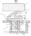
- the sealing lip provided according to the invention and molded onto the seal body prevents water from passing under the seal at the outer upper edge of the first groove and thus from entering the first groove (see Fig. 3 ). The water is thus kept completely in the outer, second groove, which is uncritical in terms of function and appearance.
- the structural outlay for the sealing element is increased only slightly, while at the same time there is a sustained improvement in the tightness.
- the cross-sectional height of the sealing lip is less than the cross-sectional height of the plug-in foot.
- the cross-sectional height of the sealing lip is less than half the cross-sectional height of the plug-in foot.
- the sealing lip has a tooth-like cross section with a tooth tip resting against the inner wall of the second groove.
- This tooth tip is preferably at least 1 mm, preferably at least 2 mm below the upper edge of the second groove on this.
- the sealing lip is spaced above the tooth tip from the wall of the second groove. As a result, any tendency of the liquid to creep between the sealing lip and the groove wall is avoided, and splash water is thus effectively prevented from migrating upwards along the wall of the second groove.
- sealing lip prefferably be convex towards the free space defined by the two grooves and/or concave towards the plug-in foot. Also these Structural design contributes to making it more difficult for water to enter the first groove.
- the cross-section of the sealing lip has a maximum width of 5 mm, preferably a maximum of 3 mm, in particular a maximum of 2 mm. It is also within the scope of the invention for the sealing lip to terminate flush with the sealing section towards the second groove.
- At least one elastic plug-in foot lip is preferably formed onto the plug-in foot, which additionally seals a gap between the plug-in foot and the wall of the first groove against the ingress of water.
- at least two vertically spaced plug-foot lips are provided, so that two additional structural measures are taken to prevent water from entering the groove base of the first groove.
- the plug-in foot lip expediently has an essentially rectangular cross section and folds upwards when it is pressed into the first groove.
- the sealing body expediently has at least one hollow chamber in the area of the sealing section.
- This hollow chamber preferably has a tooth-like hollow chamber wall on the inside. This ensures that when the seal is pressed together by the support of the sunroof, there is no sticking of the inner wall area and thus optimum resilience is guaranteed.
- the sealing body is expediently designed as a silicone profile, which can be produced in particular by means of an extrusion process.
- the subject matter of the invention is also a motor vehicle sunroof arrangement with a motor vehicle sunroof and a motor vehicle sunroof frame enclosing the motor vehicle sunroof in the closed state, the motor vehicle sunroof frame being provided with a circumferential first groove and a circumferential second groove running parallel to it on the outside, and wherein in the two grooves a sealing element of the type described above is inserted.
- the motor vehicle sunroof frame is expediently designed as a plastic injection molded part.
- the sealing element according to the invention is used in particular for a motor vehicle sunroof.
- - and thus from claim 1 in principle also included - but it is also possible to use the sealing element for other purposes, particularly in the automotive sector.
- a further preferred application of the sealing element placed under protection is in particular the sealing of a sliding side window in a motor vehicle, the position of this window being able to be changed, for example, with an electric and/or manual device.
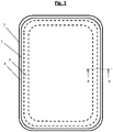
- the 1 shows a motor vehicle sunroof arrangement with a motor vehicle sunroof 1 in a plan view.
- the motor vehicle sunroof 1 is completely surrounded by a motor vehicle sunroof frame 2 in the closed state.
- the motor vehicle sunroof frame 2 is provided with a peripheral first groove 3 and a parallel peripheral second groove 4 on the outside.
- a sealing element 5 is used, which is described in detail below.
- FIG. 1 shows such a sealing element 5 according to the prior art.
- the sealing element 5 has a sealing body 6 with a plug-in base 7 and a sealing section 8 .
- the plug-in foot 7 is inserted into the first circumferential groove 3 of the motor vehicle sunroof frame 2 .
- the sunroof is on 1. It is in the 2 recognizable that water W can enter the first groove 3 via the outside second groove 4 via the boundary area G of the sealing element 5 and the inside top edge of the second groove 4 and ultimately ends up in the groove base 9 of the first groove 3 . Although this water W can be discharged from the first groove 3 via an opening 10, it is difficult to discharge this water W in such a way that there is no permanent malfunction or damage to the vehicle.
- the 3 shows a sealing element 5 according to the teaching of the invention.
- the sealing body 6 has a sealing lip 11 which engages in the outside second groove 4 of the motor vehicle sunroof frame 2 and which prevents water from entering the first groove 4 .
- the cross-sectional height h D of the sealing lip 11 is less than the cross-sectional height h S of the plug-in foot 7 , namely less than a third of the cross-sectional height h D of the plug-in foot 7 in the exemplary embodiment.
- the cross-sectional height h D of the plug-in foot 7 is a maximum of 5 mm, for example 1-5 mm, in particular 1-3 mm.
- the sealing lip 11 has a tooth-like cross section with a tooth tip 12 resting against the inner wall of the second groove 4 .
- the sealing lip 11 is spaced above the tooth tip 12 from the wall of the second groove 4 .
- the sealing lip 11 is convex towards the second groove 4 and concave towards the plug-in base 7 .
- the sealing lip 11 has a width b D of less than 3 mm in cross section. It can also be seen that towards the second groove 4 the sealing lip 11 terminates flush with the sealing section 8 and thus together forms a smooth outer surface 20 of the sealing body 6 towards the outside.
- plug-in foot 7 two vertically spaced elastic plug-in foot lips 13 are formed, which additionally seal the gap between the plug-in foot 7 and the wall of the first groove 3 against the ingress of water.
- the plug-in foot lips 13 each have an essentially rectangular cross-section and fold upwards when pressed into the first groove 3 . In the unloaded state, these two plug-in foot lips 11 are aligned essentially horizontally (indicated by dashed lines L).
- the sealing body 6 has a hollow chamber 14 in the region of the sealing section 8 which has a tooth-like hollow chamber wall 15 on the inside.
- the sealing body 6 is designed as an extruded silicone profile.
- three sealing measures a, b, c connected in series are provided, which prevent water from entering the groove base 9 of the first groove 3 .
- sealing element 5 to seal a sliding side window in a motor vehicle, the position of this sliding side window being changeable with an electric and/or manual device, for example.
Landscapes
- Engineering & Computer Science (AREA)
- Mechanical Engineering (AREA)
- Seal Device For Vehicle (AREA)
- Motor Or Generator Frames (AREA)
Description
- Die Erfindung betrifft ein Dichtungselement, insbesondere für ein Kfz-Schiebedach, mit den Merkmalen des Oberbegriffs des Patentanspruchs 1.
- Bei Kfz-Schiebedächern besteht grundsätzlich das Problem, dass auf dem Fahrzeugdach bei Regen auftreffendes oder auch stehendes Wasser durch den Übergangsbereich zwischen Kfz-Schiebedach und Kfz-Schiebedachrahmen hindurchtreten und somit letztendlich in die Fahrgastzelle oder den Innenbereich der Kfz-Karosserie eintreten und dort Schäden verursachen kann. Hierbei ist insbesondere zu berücksichtigen, dass bereits geringste Undichtigkeiten über die Jahre hinweg zu erheblichen Wasseransammlungen mit entsprechenden daraus resultierenden Problemen führen können.
- Bei einem vorbekannten Kfz-Schiebedachrahmen ist dieser mit zwei nebeneinander parallel umlaufenden Nuten versehen, die für die Anbindung des Dichtungselementes zur Verfügung stehen bzw. verhindern sollen, dass Regenwasser auf der Karrosserieoberfläche des Fahrzeugdaches steht. Eine solche im Stand der Technik bekannte Konstruktion des Dichtungselementes ist in der
Fig. 2 der Figurenbeschreibung dargestellt. Problematisch bei der vorbekannten Konstruktion ist, dass zwischen dem Dichtungselement und der äußeren Oberkante der ersten, innenseitig verlaufenden Nut geringste Wassermengen hindurchtreten können, welche sich dann in der ersten Nut bodenseitig ansammeln. Um ein Aufstauen des Regenwassers in der ersten Nut zu verhindern, ist diese am Nutgrund regelmäßig mit einer Entwässerungsöffnung versehen, welche jedoch dann die ungewünschte Feuchtigkeit lediglich in einen anderen Bereich des Fahrzeuges weiterleitet. Insgesamt ist die durch das Dichtungselement im Stand der Technik gewährleistete Abdichtung gegen Regenwasser auf Dauer unbefriedigend und es treten immer wieder Probleme mit hindurchtretendem Wasser auf, wie z.B. Korrosion bzw. Eintritt von Feuchtigkeit in die Fahrgastzelle etc. - Im Stand der Technik ist ein Dichtungselement aus der
DE 10 2005 033 276 B3 bekannt. Ferner zeigt auch dieWO 2008/068325 A1 ein ähnliches Dichtungselement für ein Kraftfahrzeug. Ein Dichtungselement mit den Merkmalen des Oberbegriffs des Patentanspruchs 1 zeigt dieWO 2015/185122 A1 . - Vor dem beschriebenen Hintergrund liegt der Erfindung die Aufgabe zugrunde, ein Dichtungselement mit den eingangs beschriebenen Merkmalen anzugeben, welches eine dauerhaft verbesserte Abdichtung gegenüber Regenwasser gewährleistet.
- Erfindungsgemäß wird diese Aufgabe durch ein Dichtungselement mit den Merkmalen des Patentanspruchs 1 gelöst. Durch die erfindungsgemäß vorgesehene, an den Dichtungskörper angeformte Dichtlippe wird verhindert, dass an der äußeren Oberkante der ersten Nut Wasser unter der Dichtung hindurchtreten und somit in die erste Nut eintreten kann (s.
Fig. 3 ). Das Wasser wird somit vollständig in der äußeren, zweiten Nut gehalten, was hinsichtlich der Funktion und auch der Optik unkritisch ist. Durch die erfindungsgemäße Maßnahme wird der konstruktive Aufwand für das Dichtungselement nur geringfügig bei gleichzeitig nachhaltiger Verbesserung der Dichtigkeit erhöht. - Erfindungsgemäß ist die Querschnittshöhe der Dichtlippe geringer als die Querschnittshöhe des Steckfußes. Hierbei beträgt die Querschnittshöhe der Dichtlippe weniger als die Hälfte der Querschnittshöhe des Steckfußes. D.h., dass mit einer lediglich kleinen Dichtungslippe, welche in den Freiraum der zweiten Nut hineinragt, die gewünschte Verbesserung der Abdichtung bereits gewährleistet werden kann.
- Erfindungsgemäß weist die Dichtlippe einen zahnartigen Querschnitt mit einer an der Innenwandung der zweiten Nut anliegenden Zahnspitze auf. Diese Zahnspitze liegt vorzugsweise mindestens 1 mm, vorzugsweise mindestens 2 mm unterhalb des oberen Randes der zweiten Nut an dieser an. Hierdurch wird der Übergang zwischen zweiter Nut und Dichtlippe nach unten verlegt, wodurch die Dichtigkeit weiter verbessert wird. Ferner ist erfindungsgemäß vorgesehen, dass die Dichtlippe oberhalb der Zahnspitze von der Wandung der zweite Nut beabstandet ist. Hierdurch wird eine sich ggf. einstellende Kriechneigung der Flüssigkeit zwischen Dichtungslippe und Nutwand vermieden und damit ein Wandern von Spritzwasser entlang der Wandung der zweiten Nut noch oben wirksam unterbunden.
- Im Rahmen der Erfindung liegt es ferner, dass die Dichtlippe zum von der zweien Nut definierten Freiraum hin konvex und / oder zum Steckfuß hin konkav ausgebildet ist. Auch diese konstruktive Gestaltung trägt dazu bei, dass ein Wassereintritt in die erste Nut erschwert wird.
- Zweckmäßigerweise weist die Dichtlippe im Querschnitt eine Breite von maximal 5 mm, vorzugsweise maximal 3 mm, insbesondere maximal 2 mm auf. Im Rahmen der Erfindung liegt es ferner, dass zur zweiten Nut hin die Dichtlippe mit dem Dichtungsabschnitt bündig abschließt.
- Vorzugsweise ist an den Steckfuß mindestens eine elastische Steckfußlippe angeformt, die einen Spalt zwischen Steckfuß und Wandung der ersten Nut zusätzlich gegen Wassereintritt abdichtet. Im Rahmen der Erfindung liegt es hierbei insbesondere, dass mindestens zwei vertikal voneinander beabstandete Steckfußlippen vorgesehen sind, sodass hiermit zwei zusätzliche konstruktive Maßnahmen vorgenommen werden, um einen Eintritt von Wasser in den Nutgrund der ersten Nut zu verhindern. Zweckmäßigerweise weist die Steckfußlippe einen im Wesentlichen rechteckförmigen Querschnitt auf und klappt beim Eindrücken in die erste Nut nach oben.
- Zweckmäßigerweise weist der Dichtungskörper im Bereich des Dichtungsabschnittes mindestens eine Hohlkammer auf. Diese Hohlkammer weist vorzugsweise eine zahnartige innenseitige Hohlkammerwandung auf. Hierdurch ist sichergestellt, dass es bei einem Zusammendrücken der Dichtung durch die Auflage des Schiebedaches zu keiner Verklebung vom Innenwandungsbereich kommt und somit ein optimales Rückstellvermögen gewährleistet ist. Der Dichtungskörper ist zweckmäßigerweise als Silikonprofil ausgebildet, welches insbesondere im Wege eines Extrusionsverfahrens hergestellt werden kann.
- Gegenstand der Erfindung ist ferner eine Kfz-Schiebedachanordnung mit einem Kfz-Schiebedach und einem das Kfz-Schiebedach im Schließzustand einfassenden Kfz-Schiebedachrahmen, wobei der Kfz-Schiebedachrahmen mit einer umlaufenden ersten Nut und einer außenseitig daneben parallel verlaufenden umlaufenden zweiten Nut versehen ist, und wobei in die beiden Nuten ein Dichtungselement der vorstehend beschriebenen Art eingesetzt ist. Der Kfz-Schiebedachrahmen ist zweckmäßigerweise als Kunststoff-Spritzgussteil ausgebildet.
- Wie erläutert, findet das erfindungsgemäße Dichtungselement insbesondere Einsatz für ein Kfz-Schiebedach. Im Rahmen der Erfindung - und damit vom Patentanspruch 1 grundsätzlich ebenfalls umfasst - liegt es jedoch auch, das Dichtungselement für andere Zwecke, insbesondere im Automobilbereich einzusetzen. Eine weitere bevorzugte Anwendung des unter Schutz gestellten Dichtungselementes ist insbesondere die Abdichtung eines Kfz-Seitenschiebefensters, wobei die Position dieses Fensters z.B. mit einer elektrischen und/oder manuellen Vorrichtung verändert werden kann.
- Im Folgenden wird die Erfindung anhand einer lediglich ein Ausführungsbeispiel darstellenden Zeichnung ausführlich erläutert. Es zeigen schematisch:
- Fig. 1:
- eine Kfz-Schiebedachanordnung in einer Draufsicht auf das Kraftfahrzeug,
- Fig. 2:
- ein Dichtungselement für das in
Fig. 1 dargestellte Kfz-Schiebedach gemäß dem Stand in einer Querschnittsdarstellung gemäß dem Schnitt A - A inFig. 1 und - Fig. 3:
- ein erfindungsgemäßes Dichtungselement einer der
Fig. 2 entsprechenden Darstellung. - Die
Fig. 1 zeigt in einer Draufsicht eine Kfz-Schiebedachanordnung mit einem Kfz-Schiebedach 1. Das Kfz-Schiebedach 1 ist im Schließzustand vollständig von einem Kfz-Schiebedachrahmen 2 eingefasst. Der Kfz-Schiebedachrahmen 2 ist mit einer umlaufenden ersten Nut 3 und einer außenseitig daneben parallel umlaufenden zweiten Nut 4 versehen. In die beiden Nuten 3, 4 ist ein Dichtungselement 5 eingesetzt, welches nachfolgend ausführlich beschrieben wird. - Die
Fig. 2 zeigt in solches Dichtungselement 5 gemäß dem Stand der Technik. Das Dichtungselement 5 weist einen Dichtungskörper 6 mit einem Steckfuß 7 und einem Dichtungsabschnitt 8 auf. Der Steckfuß 7 ist in die erste umlaufende Nut 3 des Kfz-Schiebedachrahmens 2 eingesetzt. Auf dem elastischen Dichtungsabschnitt 8 liegt das Kfz-Schiebedach auf 1. Es ist in derFig. 2 erkennbar, dass Wasser W über die außenseitige zweite Nut 4 über den Grenzbereich G von Dichtungselement 5 und innenseitiger Oberkante der zweiten Nut 4 in die erste Nut 3 eindringen kann und hierüber letztendlich im Nutgrund 9 der ersten Nut 3 landet. Zwar kann dieses Wasser W über eine Öffnung 10 aus der ersten Nut 3 abgeleitet werden, eine Ableitung dieses Wassers W derart, dass es dauerhaft zu keiner Funktionsstörung bzw. Beschädigung des Fahrzeuges kommt, ist jedoch schwierig. - Die
Fig. 3 zeigt ein Dichtungselement 5 gemäß der erfindungsgemäßen Lehre. Es ist erkennbar, dass der Dichtungskörper 6 eine in die außenseitige zweite Nut 4 des Kfz-Schiebedachrahmens 2 eingreifende Dichtlippe 11 aufweist, die einen Eintritt von Wasser in die erste Nut 4 verhindert. Es ist ferner erkennbar, dass die Querschnittshöhe hD der Dichtlippe 11 geringer als die Querschnittshöhe hS des Steckfußes 7 ist, nämlich im Ausführungsbeispiel weniger als ein Drittel der Querschnittshöhe hD des Steckfußes 7 beträgt. Die Querschnittshöhe hD des Steckfußes 7 beträgt maximal 5 mm, z.B. 1 - 5 mm, insbesondere 1 - 3 mm. Die Dichtlippe 11 weist einen zahnartigen Querschnitt mit einer an der Innenwandung der zweiten Nut 4 anliegenden Zahnspitze 12 auf. Die Dichtlippe 11 ist oberhalb der Zahnspitze 12 von der Wandung der zweiten Nut 4 beabstandet. Ferner ist die Dichtlippe 11 zur zweiten Nut 4 hin konvex und zum Steckfuß 7 hin konkav ausgebildet. Die Dichtlippe 11 weist im Ausführungsbeispiel im Querschnitt eine Breite bD von weniger als 3 mm auf. Es ist ferner erkennbar, dass zur zweiten Nut 4 hin die Dichtlippe 11 mit dem Dichtungsabschnitt 8 bündig abschließt und somit nach außen hin gemeinsam eine glatte Außenfläche 20 des Dichtungskörpers 6 bildet. - An den Steckfuß 7 sind zwei vertikal voneinander beabstandete elastische Steckfußlippen 13 angeformt, die den Spalt zwischen Steckfuß 7 und Wandung der ersten Nut 3 zusätzlich gegen Wassereintritt abdichten. Die Steckfußlippen 13 weisen jeweils einen im Wesentlichen rechteckförmigen Querschnitt auf und klappen beim Eindrücken in die erste Nut 3 nach oben. Im unbelasteten Zustand sind diese beiden Steckfußlippen 11 im Wesentlichen horizontal ausgerichtet (durch gestrichelte Linien L angedeutet). Es ist ferner erkennbar, dass der Dichtungskörper 6 im Bereich des Dichtungsabschnittes 8 eine Hohlkammer 14 aufweist, die innenseitig eine zahnartige Hohlkammerwandung 15 aufweist. Der Dichtungskörper 6 ist als extrudiertes Silikonprofil ausgebildet. Insgesamt sind erfindungsgemäß also drei hintereinander geschaltete Abdichtungsmaßnahmen a, b, c vorgesehen, die einen Eintritt von Wasser in den Nutgrund 9 der ersten Nut 3 verhindern.
- In den Figuren nicht dargestellt, jedoch im Rahmen der Erfindung liegt es ebenso, das Dichtungselement 5 zur Abdichtung eines Kfz-Seitenschiebefensters einzusetzen, wobei die Position dieses Seitenschiebefensters z.B. mit einer elektrischen und/oder manuellen Vorrichtung verändert werden kann.
Claims (10)
- Dichtungselement (5), insbesondere für ein Kfz-Schiebedach (1), mit- einem Dichtungskörper (6) mit einem Steckfuß (7) und einem Dichtungsabschnitt (8),- wobei der Steckfuß (7) in eine erste, vorzugsweise umlaufende, Nut (3) eines das Kfz-Schiebedach (1) im Schließzustand einfassenden Kfz-Schiebedachrahmens (2) einsetzbar ist und- wobei auf den elastischen Dichtungsabschnitt (8) das Kfz-Schiebedach (1) auflegbar ist,- wobei der Dichtungskörper (6) mindestens eine in eine - zur ersten Nut (3) außenseitig benachbarte und parallele, vorzugsweise ebenfalls umlaufende - zweite Nut (4) des Kfz-Schiebedachrahmens (2) einen Eingriff erlaubende Dichtlippe (11) aufweist, die einen Eintritt von Wasser (W) in die erste Nut (3) verhindert,- wobei die Dichtlippe (11) einen zahnartigen Querschnitt mit einer an der Innenwandung der zweiten Nut (4) anliegenden Zahnspitze (12) aufweist, und- wobei die Dichtlippe (11) oberhalb der Zahnspitze (12) von der Wandung der zweiten Nut (4) beabstandet ist,dadurch gekennzeichnet, dass die Querschnittshöhe (hD) der Dichtlippe (11) weniger als die Hälfte der Querschnittshöhe (hS) des Steckfußes (7) beträgt.
- Dichtungselement (5) nach Anspruch 1, dadurch gekennzeichnet, dass die Dichtlippe (11) zur zweiten Nut (4) hin konvex und/oder zum Steckfuß (7) hin konkav ausgebildet ist.
- Dichtungselement (5) nach Anspruch 1 oder 2, dadurch gekennzeichnet, dass die Dichtlippe (11) im Querschnitt eine Breite (bo) von maximal 5 mm, vorzugsweise maximal 3 mm aufweist.
- Dichtungselement (5) nach einem der Ansprüche 1 bis 3, dadurch gekennzeichnet, dass zur zweiten Nut (4) hin die Dichtlippe (11) mit dem Dichtungsabschnitt (8) bündig abschließt.
- Dichtungselement (5) nach einem der Ansprüche 1 bis 4, dadurch gekennzeichnet, dass an den Steckfuß (7) mindestens eine elastische Steckfußlippe (13) angeformt ist, die einen Spalt zwischen Steckfuß (7) und Wandung der ersten Nut (3) zusätzlich gegen den Eintritt von Wasser (W) abdichtet.
- Dichtungselement (5) nach Anspruch 5, dadurch gekennzeichnet, dass die Steckfußlippe (13) einen im Wesentlichen rechteckförmigen Querschnitt aufweist und beim Eindrücken in die erste Nut (3) nach oben klappt.
- Dichtungselement (5) nach einem der Ansprüche 1 bis 6, dadurch gekennzeichnet, dass der Dichtungskörper (6) mindestens eine Hohlkammer (14) aufweist, die vorzugsweise eine zahnartige innenseitige Hohlkammerwandung (15) besitzt.
- Dichtungselement (5) nach einem der Ansprüche 1 bis 7, dadurch gekennzeichnet, dass der Dichtungskörper (6) als, vorzugsweise extrudiertes, Silikonprofil ausgebildet ist.
- Kfz-Schiebedachanordnung mit- einem Kfz-Schiebedach (1) und- einem das Kfz-Schiebedach (1) im Schließzustand einfassenden Kfz-Schiebedachrahmen (2),wobei der Kfz-Schiebedachrahmen (2) mit einer umlaufenden ersten Nut (3) und einer außenseitig daneben parallel umlaufenden zweiten Nut (4) versehen ist, und wobei in die beiden Nuten (3, 4) ein Dichtungselement (5) nach einem der Ansprüche 1 bis 8 eingesetzt ist.
- Kfz-Schiebedachanordnung nach Anspruch 9, wobei der Kfz-Schiebedachrahmen (2) als Kunststoff-Spritzgussteil ausgebildet ist.
Applications Claiming Priority (3)
| Application Number | Priority Date | Filing Date | Title |
|---|---|---|---|
| DE202016107342.1U DE202016107342U1 (de) | 2016-12-23 | 2016-12-23 | Dichtungselement für ein Kfz-Schiebedach |
| DE102017108111.9A DE102017108111A1 (de) | 2016-12-23 | 2017-04-13 | Dichtungselement, insbesondere für ein Kfz-Schiebedach |
| PCT/EP2017/001418 WO2018114040A1 (de) | 2016-12-23 | 2017-12-12 | Dichtungselement, insbesondere für ein kfz-schiebedach |
Publications (2)
| Publication Number | Publication Date |
|---|---|
| EP3558733A1 EP3558733A1 (de) | 2019-10-30 |
| EP3558733B1 true EP3558733B1 (de) | 2022-04-13 |
Family
ID=61912700
Family Applications (1)
| Application Number | Title | Priority Date | Filing Date |
|---|---|---|---|
| EP17825744.0A Active EP3558733B1 (de) | 2016-12-23 | 2017-12-12 | Dichtungselement, insbesondere für ein kfz-schiebedach |
Country Status (4)
| Country | Link |
|---|---|
| EP (1) | EP3558733B1 (de) |
| CN (1) | CN110099811B (de) |
| DE (2) | DE202016107342U1 (de) |
| WO (1) | WO2018114040A1 (de) |
Families Citing this family (4)
| Publication number | Priority date | Publication date | Assignee | Title |
|---|---|---|---|---|
| DE102019131461B4 (de) * | 2019-11-21 | 2026-01-22 | Webasto SE | Anordnung für ein Fahrzeugdach und Fahrzeugdach für ein Kraftfahrzeug |
| DE202019106653U1 (de) * | 2019-11-29 | 2021-03-02 | Rehau Ag + Co | Trägervorrichtung für ein Außenverkleidungsteil eines Kraftfahrzeugs |
| CN112277601A (zh) * | 2020-09-21 | 2021-01-29 | 芜湖莫森泰克汽车科技股份有限公司 | 一种全景天窗顶盖密封条结构 |
| DE102023117301A1 (de) | 2023-06-30 | 2025-01-02 | Bayerische Motoren Werke Aktiengesellschaft | Dichtungselement, Dichtungsträger, Dichtungssystem, Montierwerkzeug zum Montieren des Dichtungssystems sowie Kraftfahrzeug |
Citations (1)
| Publication number | Priority date | Publication date | Assignee | Title |
|---|---|---|---|---|
| WO2015185122A1 (en) * | 2014-06-04 | 2015-12-10 | Webasto SE | Sealing for a movable vehicle roof panel |
Family Cites Families (17)
| Publication number | Priority date | Publication date | Assignee | Title |
|---|---|---|---|---|
| DE3146908C2 (de) * | 1981-11-26 | 1987-03-19 | Rockwell Golde Gmbh, 6000 Frankfurt | Randspaltabdichtung an einem Kraftfahrzeugschiebedach |
| JPH0324411Y2 (de) * | 1984-12-14 | 1991-05-28 | ||
| US4783116A (en) * | 1985-02-07 | 1988-11-08 | Empire Automotive, Inc. | Sunroof frame assembly for vehicles |
| EP0253632A3 (de) * | 1986-07-14 | 1989-02-08 | Carvalette Services Africa (Proprietary) Limited | Sonnendach für ein Kraftfahrzeug |
| GB8713864D0 (en) * | 1987-06-13 | 1987-07-15 | Britax Weathershields | Opening roof for motor vehicle |
| GB2214874A (en) * | 1988-02-10 | 1989-09-13 | Arrowin Ltd | Vehicle sunroof |
| US6478308B1 (en) * | 2000-01-10 | 2002-11-12 | Overhead Door Corporation | Replaceable door seal and retainer assemblies |
| DE20201304U1 (de) * | 2002-01-28 | 2002-06-20 | Webasto Vehicle Systems International GmbH, 82131 Stockdorf | Vorrichtung zum Öffnen und Schließen mindestens einer Öffnung in einem Fahrzeugdach mit mindestens einem Deckel |
| DE102005033276B3 (de) * | 2005-07-15 | 2006-10-19 | Webasto Ag | Dachaufbau mit einem Dachausschnitt und Dichtung hierfür |
| FR2909594B1 (fr) * | 2006-12-06 | 2011-06-10 | Wagon Sas | Pavillon vitre de vehicule automobile,procede de montage et vehicule correspondants |
| US8516749B2 (en) * | 2008-02-20 | 2013-08-27 | Pilkington Group Limited | Encapsulated window assembly with integral seal and method of installing game |
| EP2301785B1 (de) * | 2009-09-23 | 2012-08-08 | Advanced Comfort Systems France SAS - ACS France | Verschlussvorrichtung eines Dachausschnittes eines Kraftfahrzeugs , mit einer Abdichtungssperre und einer nach außen gerichteten Wasserableitung |
| JP5664134B2 (ja) * | 2010-11-05 | 2015-02-04 | アイシン精機株式会社 | ルーフ装置 |
| FR2985225B1 (fr) * | 2011-12-30 | 2014-01-03 | Acs France Sas | Pavillon vitre de vehicule, equipe d'un panneau mobile coulissant, et vehicule correspondant |
| TWI529078B (zh) * | 2013-10-01 | 2016-04-11 | 信昌機械廠股份有限公司 | 汽車天窗 |
| JP6316615B2 (ja) * | 2014-02-12 | 2018-04-25 | 八千代工業株式会社 | サンルーフパネルのシール取付構造 |
| DE102015207817B4 (de) * | 2015-04-28 | 2025-02-20 | Ford Global Technologies, Llc | Dichtungsanordnung einer Fensterscheibe |
-
2016
- 2016-12-23 DE DE202016107342.1U patent/DE202016107342U1/de not_active Expired - Lifetime
-
2017
- 2017-04-13 DE DE102017108111.9A patent/DE102017108111A1/de not_active Withdrawn
- 2017-12-12 CN CN201780080194.2A patent/CN110099811B/zh active Active
- 2017-12-12 WO PCT/EP2017/001418 patent/WO2018114040A1/de not_active Ceased
- 2017-12-12 EP EP17825744.0A patent/EP3558733B1/de active Active
Patent Citations (1)
| Publication number | Priority date | Publication date | Assignee | Title |
|---|---|---|---|---|
| WO2015185122A1 (en) * | 2014-06-04 | 2015-12-10 | Webasto SE | Sealing for a movable vehicle roof panel |
Also Published As
| Publication number | Publication date |
|---|---|
| DE202016107342U1 (de) | 2018-03-26 |
| DE102017108111A1 (de) | 2018-06-28 |
| EP3558733A1 (de) | 2019-10-30 |
| WO2018114040A1 (de) | 2018-06-28 |
| CN110099811B (zh) | 2023-03-17 |
| CN110099811A (zh) | 2019-08-06 |
Similar Documents
| Publication | Publication Date | Title |
|---|---|---|
| EP3558733B1 (de) | Dichtungselement, insbesondere für ein kfz-schiebedach | |
| EP3634796B1 (de) | Dichtungsanordnung | |
| EP2982531B1 (de) | Eckausbildung einer hohlkammerdichtung | |
| WO2016198217A1 (de) | Profilleiste, system und verfahren zur herstellung einer profilleiste | |
| EP1839953B1 (de) | Dichtungseinheit für ein Hohlprofil einer Fahrzeugkarosserie | |
| DE3941045C2 (de) | Dichtungsstreifen | |
| DE9006595U1 (de) | Abdicht- und Führungsvorrichtung für ein eine verschiebbare Fensterscheibe aufweisendes Fenster | |
| DE10116456A1 (de) | Dachmodul für ein Fahrzeug | |
| DE68915060T2 (de) | Dichtungselement für Kraftfahrzeuge. | |
| DE102005022582B4 (de) | Blendleiste und Dichtungsanordnung | |
| DE2461508C3 (de) | Abdichtung | |
| DE102020132530A1 (de) | Dachholm mit einer trennwand, die dazu konfiguriert ist, einer klemmkraft zu widerstehen | |
| EP1080969A2 (de) | Deckel eines Fahrzeugdaches mit Kunststoffrahmen und Randspaltdichtung sowie Verfahren zur Herstellung eines solchen Deckels | |
| DE102011001283B4 (de) | Türanordnung | |
| EP1818203A1 (de) | Dichtungselement für eine Sichtscheibe | |
| DE19832379C2 (de) | Schiebedach für ein Kraftfahrzeug | |
| DE898560C (de) | Regendichtung mit Ableitungskanal bei Drehfenstern fuer Fahrzeuge zur zugfreien Wagenlueftung | |
| DE102011010773A1 (de) | Rahmenkonstruktion für ein Fenster oder eine Tür | |
| EP0170870B1 (de) | Verfahren zum Herstellen von Dichtungsprofilleisten | |
| DE10046975A1 (de) | Elastisches Hohlprofil und Verfahren zu seiner Herstellung | |
| EP2924225A1 (de) | Fenster oder tür mit dichtung | |
| DE102006038000B3 (de) | Dichtungsanordnung für ein verstellbares Fahrzeugdach | |
| DE102019116824A1 (de) | Dichtungsanordnung für ein Fahrzeugfenster, Fahrzeugtür und Kraftfahrzeug | |
| DE20320515U1 (de) | Fahrzeugdach mit Geräuschreduzierung | |
| EP2281705B1 (de) | Blende für ein Kraftfahrzeug |
Legal Events
| Date | Code | Title | Description |
|---|---|---|---|
| STAA | Information on the status of an ep patent application or granted ep patent |
Free format text: STATUS: UNKNOWN |
|
| STAA | Information on the status of an ep patent application or granted ep patent |
Free format text: STATUS: THE INTERNATIONAL PUBLICATION HAS BEEN MADE |
|
| PUAI | Public reference made under article 153(3) epc to a published international application that has entered the european phase |
Free format text: ORIGINAL CODE: 0009012 |
|
| STAA | Information on the status of an ep patent application or granted ep patent |
Free format text: STATUS: REQUEST FOR EXAMINATION WAS MADE |
|
| 17P | Request for examination filed |
Effective date: 20190617 |
|
| AK | Designated contracting states |
Kind code of ref document: A1 Designated state(s): AL AT BE BG CH CY CZ DE DK EE ES FI FR GB GR HR HU IE IS IT LI LT LU LV MC MK MT NL NO PL PT RO RS SE SI SK SM TR |
|
| AX | Request for extension of the european patent |
Extension state: BA ME |
|
| DAV | Request for validation of the european patent (deleted) | ||
| DAX | Request for extension of the european patent (deleted) | ||
| RAP1 | Party data changed (applicant data changed or rights of an application transferred) |
Owner name: REHAU AG + CO |
|
| STAA | Information on the status of an ep patent application or granted ep patent |
Free format text: STATUS: EXAMINATION IS IN PROGRESS |
|
| 17Q | First examination report despatched |
Effective date: 20210112 |
|
| GRAP | Despatch of communication of intention to grant a patent |
Free format text: ORIGINAL CODE: EPIDOSNIGR1 |
|
| STAA | Information on the status of an ep patent application or granted ep patent |
Free format text: STATUS: GRANT OF PATENT IS INTENDED |
|
| INTG | Intention to grant announced |
Effective date: 20211007 |
|
| GRAS | Grant fee paid |
Free format text: ORIGINAL CODE: EPIDOSNIGR3 |
|
| GRAA | (expected) grant |
Free format text: ORIGINAL CODE: 0009210 |
|
| STAA | Information on the status of an ep patent application or granted ep patent |
Free format text: STATUS: THE PATENT HAS BEEN GRANTED |
|
| RAP1 | Party data changed (applicant data changed or rights of an application transferred) |
Owner name: REHAU INDUSTRIES SE & CO. KG |
|
| AK | Designated contracting states |
Kind code of ref document: B1 Designated state(s): AL AT BE BG CH CY CZ DE DK EE ES FI FR GB GR HR HU IE IS IT LI LT LU LV MC MK MT NL NO PL PT RO RS SE SI SK SM TR |
|
| REG | Reference to a national code |
Ref country code: GB Ref legal event code: FG4D Free format text: NOT ENGLISH |
|
| REG | Reference to a national code |
Ref country code: CH Ref legal event code: EP |
|
| REG | Reference to a national code |
Ref country code: DE Ref legal event code: R096 Ref document number: 502017012998 Country of ref document: DE |
|
| REG | Reference to a national code |
Ref country code: IE Ref legal event code: FG4D Free format text: LANGUAGE OF EP DOCUMENT: GERMAN |
|
| REG | Reference to a national code |
Ref country code: AT Ref legal event code: REF Ref document number: 1483129 Country of ref document: AT Kind code of ref document: T Effective date: 20220515 |
|
| REG | Reference to a national code |
Ref country code: LT Ref legal event code: MG9D |
|
| REG | Reference to a national code |
Ref country code: NL Ref legal event code: MP Effective date: 20220413 |
|
| RAP4 | Party data changed (patent owner data changed or rights of a patent transferred) |
Owner name: REHAU INDUSTRIES SE & CO. KG |
|
| PG25 | Lapsed in a contracting state [announced via postgrant information from national office to epo] |
Ref country code: NL Free format text: LAPSE BECAUSE OF FAILURE TO SUBMIT A TRANSLATION OF THE DESCRIPTION OR TO PAY THE FEE WITHIN THE PRESCRIBED TIME-LIMIT Effective date: 20220413 |
|
| REG | Reference to a national code |
Ref country code: DE Ref legal event code: R081 Ref document number: 502017012998 Country of ref document: DE Owner name: SILNOVA GMBH, DE Free format text: FORMER OWNER: REHAU INDUSTRIES SE & CO. KG, 95111 REHAU, DE |
|
| PG25 | Lapsed in a contracting state [announced via postgrant information from national office to epo] |
Ref country code: SE Free format text: LAPSE BECAUSE OF FAILURE TO SUBMIT A TRANSLATION OF THE DESCRIPTION OR TO PAY THE FEE WITHIN THE PRESCRIBED TIME-LIMIT Effective date: 20220413 Ref country code: PT Free format text: LAPSE BECAUSE OF FAILURE TO SUBMIT A TRANSLATION OF THE DESCRIPTION OR TO PAY THE FEE WITHIN THE PRESCRIBED TIME-LIMIT Effective date: 20220816 Ref country code: NO Free format text: LAPSE BECAUSE OF FAILURE TO SUBMIT A TRANSLATION OF THE DESCRIPTION OR TO PAY THE FEE WITHIN THE PRESCRIBED TIME-LIMIT Effective date: 20220713 Ref country code: LT Free format text: LAPSE BECAUSE OF FAILURE TO SUBMIT A TRANSLATION OF THE DESCRIPTION OR TO PAY THE FEE WITHIN THE PRESCRIBED TIME-LIMIT Effective date: 20220413 Ref country code: HR Free format text: LAPSE BECAUSE OF FAILURE TO SUBMIT A TRANSLATION OF THE DESCRIPTION OR TO PAY THE FEE WITHIN THE PRESCRIBED TIME-LIMIT Effective date: 20220413 Ref country code: GR Free format text: LAPSE BECAUSE OF FAILURE TO SUBMIT A TRANSLATION OF THE DESCRIPTION OR TO PAY THE FEE WITHIN THE PRESCRIBED TIME-LIMIT Effective date: 20220714 Ref country code: FI Free format text: LAPSE BECAUSE OF FAILURE TO SUBMIT A TRANSLATION OF THE DESCRIPTION OR TO PAY THE FEE WITHIN THE PRESCRIBED TIME-LIMIT Effective date: 20220413 Ref country code: ES Free format text: LAPSE BECAUSE OF FAILURE TO SUBMIT A TRANSLATION OF THE DESCRIPTION OR TO PAY THE FEE WITHIN THE PRESCRIBED TIME-LIMIT Effective date: 20220413 Ref country code: BG Free format text: LAPSE BECAUSE OF FAILURE TO SUBMIT A TRANSLATION OF THE DESCRIPTION OR TO PAY THE FEE WITHIN THE PRESCRIBED TIME-LIMIT Effective date: 20220713 |
|
| PG25 | Lapsed in a contracting state [announced via postgrant information from national office to epo] |
Ref country code: RS Free format text: LAPSE BECAUSE OF FAILURE TO SUBMIT A TRANSLATION OF THE DESCRIPTION OR TO PAY THE FEE WITHIN THE PRESCRIBED TIME-LIMIT Effective date: 20220413 Ref country code: PL Free format text: LAPSE BECAUSE OF FAILURE TO SUBMIT A TRANSLATION OF THE DESCRIPTION OR TO PAY THE FEE WITHIN THE PRESCRIBED TIME-LIMIT Effective date: 20220413 Ref country code: LV Free format text: LAPSE BECAUSE OF FAILURE TO SUBMIT A TRANSLATION OF THE DESCRIPTION OR TO PAY THE FEE WITHIN THE PRESCRIBED TIME-LIMIT Effective date: 20220413 Ref country code: IS Free format text: LAPSE BECAUSE OF FAILURE TO SUBMIT A TRANSLATION OF THE DESCRIPTION OR TO PAY THE FEE WITHIN THE PRESCRIBED TIME-LIMIT Effective date: 20220813 |
|
| RAP2 | Party data changed (patent owner data changed or rights of a patent transferred) |
Owner name: SILNOVA GMBH |
|
| REG | Reference to a national code |
Ref country code: BE Ref legal event code: PD Owner name: SILNOVA GMBH; DE Free format text: DETAILS ASSIGNMENT: CHANGE OF OWNER(S), ASSIGNMENT; FORMER OWNER NAME: REHAU INDUSTRIES SE & CO. KG Effective date: 20221108 |
|
| REG | Reference to a national code |
Ref country code: GB Ref legal event code: 732E Free format text: REGISTERED BETWEEN 20221117 AND 20221123 |
|
| REG | Reference to a national code |
Ref country code: DE Ref legal event code: R097 Ref document number: 502017012998 Country of ref document: DE |
|
| PG25 | Lapsed in a contracting state [announced via postgrant information from national office to epo] |
Ref country code: SM Free format text: LAPSE BECAUSE OF FAILURE TO SUBMIT A TRANSLATION OF THE DESCRIPTION OR TO PAY THE FEE WITHIN THE PRESCRIBED TIME-LIMIT Effective date: 20220413 Ref country code: SK Free format text: LAPSE BECAUSE OF FAILURE TO SUBMIT A TRANSLATION OF THE DESCRIPTION OR TO PAY THE FEE WITHIN THE PRESCRIBED TIME-LIMIT Effective date: 20220413 Ref country code: RO Free format text: LAPSE BECAUSE OF FAILURE TO SUBMIT A TRANSLATION OF THE DESCRIPTION OR TO PAY THE FEE WITHIN THE PRESCRIBED TIME-LIMIT Effective date: 20220413 Ref country code: EE Free format text: LAPSE BECAUSE OF FAILURE TO SUBMIT A TRANSLATION OF THE DESCRIPTION OR TO PAY THE FEE WITHIN THE PRESCRIBED TIME-LIMIT Effective date: 20220413 Ref country code: DK Free format text: LAPSE BECAUSE OF FAILURE TO SUBMIT A TRANSLATION OF THE DESCRIPTION OR TO PAY THE FEE WITHIN THE PRESCRIBED TIME-LIMIT Effective date: 20220413 Ref country code: CZ Free format text: LAPSE BECAUSE OF FAILURE TO SUBMIT A TRANSLATION OF THE DESCRIPTION OR TO PAY THE FEE WITHIN THE PRESCRIBED TIME-LIMIT Effective date: 20220413 |
|
| PLBE | No opposition filed within time limit |
Free format text: ORIGINAL CODE: 0009261 |
|
| STAA | Information on the status of an ep patent application or granted ep patent |
Free format text: STATUS: NO OPPOSITION FILED WITHIN TIME LIMIT |
|
| 26N | No opposition filed |
Effective date: 20230116 |
|
| PG25 | Lapsed in a contracting state [announced via postgrant information from national office to epo] |
Ref country code: AL Free format text: LAPSE BECAUSE OF FAILURE TO SUBMIT A TRANSLATION OF THE DESCRIPTION OR TO PAY THE FEE WITHIN THE PRESCRIBED TIME-LIMIT Effective date: 20220413 |
|
| REG | Reference to a national code |
Ref country code: DE Ref legal event code: R082 Ref document number: 502017012998 Country of ref document: DE |
|
| REG | Reference to a national code |
Ref country code: AT Ref legal event code: PC Ref document number: 1483129 Country of ref document: AT Kind code of ref document: T Owner name: SILNOVA GMBH, DE Effective date: 20230320 |
|
| PG25 | Lapsed in a contracting state [announced via postgrant information from national office to epo] |
Ref country code: SI Free format text: LAPSE BECAUSE OF FAILURE TO SUBMIT A TRANSLATION OF THE DESCRIPTION OR TO PAY THE FEE WITHIN THE PRESCRIBED TIME-LIMIT Effective date: 20220413 |
|
| REG | Reference to a national code |
Ref country code: DE Ref legal event code: R081 Ref document number: 502017012998 Country of ref document: DE Owner name: SILNOVA GMBH, DE Free format text: FORMER OWNER: SILNOVA GMBH, 95233 HELMBRECHTS, DE |
|
| REG | Reference to a national code |
Ref country code: LU Ref legal event code: HC Owner name: SILNOVA GMBH; DE Free format text: FORMER OWNER: SILNOVA GMBH Effective date: 20230904 |
|
| PGFP | Annual fee paid to national office [announced via postgrant information from national office to epo] |
Ref country code: LU Payment date: 20231128 Year of fee payment: 7 |
|
| PG25 | Lapsed in a contracting state [announced via postgrant information from national office to epo] |
Ref country code: IT Free format text: LAPSE BECAUSE OF FAILURE TO SUBMIT A TRANSLATION OF THE DESCRIPTION OR TO PAY THE FEE WITHIN THE PRESCRIBED TIME-LIMIT Effective date: 20220413 |
|
| PGFP | Annual fee paid to national office [announced via postgrant information from national office to epo] |
Ref country code: IE Payment date: 20231124 Year of fee payment: 7 Ref country code: AT Payment date: 20231127 Year of fee payment: 7 |
|
| PGFP | Annual fee paid to national office [announced via postgrant information from national office to epo] |
Ref country code: BE Payment date: 20231124 Year of fee payment: 7 |
|
| PG25 | Lapsed in a contracting state [announced via postgrant information from national office to epo] |
Ref country code: HU Free format text: LAPSE BECAUSE OF FAILURE TO SUBMIT A TRANSLATION OF THE DESCRIPTION OR TO PAY THE FEE WITHIN THE PRESCRIBED TIME-LIMIT; INVALID AB INITIO Effective date: 20171212 |
|
| PG25 | Lapsed in a contracting state [announced via postgrant information from national office to epo] |
Ref country code: CY Free format text: LAPSE BECAUSE OF FAILURE TO SUBMIT A TRANSLATION OF THE DESCRIPTION OR TO PAY THE FEE WITHIN THE PRESCRIBED TIME-LIMIT Effective date: 20220413 |
|
| PGFP | Annual fee paid to national office [announced via postgrant information from national office to epo] |
Ref country code: CH Payment date: 20240101 Year of fee payment: 7 |
|
| PG25 | Lapsed in a contracting state [announced via postgrant information from national office to epo] |
Ref country code: MK Free format text: LAPSE BECAUSE OF FAILURE TO SUBMIT A TRANSLATION OF THE DESCRIPTION OR TO PAY THE FEE WITHIN THE PRESCRIBED TIME-LIMIT Effective date: 20220413 |
|
| PG25 | Lapsed in a contracting state [announced via postgrant information from national office to epo] |
Ref country code: MC Free format text: LAPSE BECAUSE OF FAILURE TO SUBMIT A TRANSLATION OF THE DESCRIPTION OR TO PAY THE FEE WITHIN THE PRESCRIBED TIME-LIMIT Effective date: 20220413 |
|
| PG25 | Lapsed in a contracting state [announced via postgrant information from national office to epo] |
Ref country code: MC Free format text: LAPSE BECAUSE OF FAILURE TO SUBMIT A TRANSLATION OF THE DESCRIPTION OR TO PAY THE FEE WITHIN THE PRESCRIBED TIME-LIMIT Effective date: 20220413 |
|
| PG25 | Lapsed in a contracting state [announced via postgrant information from national office to epo] |
Ref country code: MT Free format text: LAPSE BECAUSE OF FAILURE TO SUBMIT A TRANSLATION OF THE DESCRIPTION OR TO PAY THE FEE WITHIN THE PRESCRIBED TIME-LIMIT Effective date: 20220413 |
|
| PG25 | Lapsed in a contracting state [announced via postgrant information from national office to epo] |
Ref country code: BG Free format text: LAPSE BECAUSE OF FAILURE TO SUBMIT A TRANSLATION OF THE DESCRIPTION OR TO PAY THE FEE WITHIN THE PRESCRIBED TIME-LIMIT Effective date: 20220413 |
|
| PG25 | Lapsed in a contracting state [announced via postgrant information from national office to epo] |
Ref country code: BG Free format text: LAPSE BECAUSE OF FAILURE TO SUBMIT A TRANSLATION OF THE DESCRIPTION OR TO PAY THE FEE WITHIN THE PRESCRIBED TIME-LIMIT Effective date: 20220413 |
|
| REG | Reference to a national code |
Ref country code: CH Ref legal event code: PL |
|
| REG | Reference to a national code |
Ref country code: AT Ref legal event code: MM01 Ref document number: 1483129 Country of ref document: AT Kind code of ref document: T Effective date: 20241212 |
|
| PG25 | Lapsed in a contracting state [announced via postgrant information from national office to epo] |
Ref country code: LU Free format text: LAPSE BECAUSE OF NON-PAYMENT OF DUE FEES Effective date: 20241212 |
|
| REG | Reference to a national code |
Ref country code: BE Ref legal event code: MM Effective date: 20241231 |
|
| PG25 | Lapsed in a contracting state [announced via postgrant information from national office to epo] |
Ref country code: BE Free format text: LAPSE BECAUSE OF NON-PAYMENT OF DUE FEES Effective date: 20241231 |
|
| PG25 | Lapsed in a contracting state [announced via postgrant information from national office to epo] |
Ref country code: AT Free format text: LAPSE BECAUSE OF NON-PAYMENT OF DUE FEES Effective date: 20241212 |
|
| PG25 | Lapsed in a contracting state [announced via postgrant information from national office to epo] |
Ref country code: CH Free format text: LAPSE BECAUSE OF NON-PAYMENT OF DUE FEES Effective date: 20241231 |
|
| PG25 | Lapsed in a contracting state [announced via postgrant information from national office to epo] |
Ref country code: IE Free format text: LAPSE BECAUSE OF NON-PAYMENT OF DUE FEES Effective date: 20241212 |
|
| PG25 | Lapsed in a contracting state [announced via postgrant information from national office to epo] |
Ref country code: TR Free format text: LAPSE BECAUSE OF FAILURE TO SUBMIT A TRANSLATION OF THE DESCRIPTION OR TO PAY THE FEE WITHIN THE PRESCRIBED TIME-LIMIT Effective date: 20220413 |
|
| PGFP | Annual fee paid to national office [announced via postgrant information from national office to epo] |
Ref country code: GB Payment date: 20251111 Year of fee payment: 9 |
|
| PGFP | Annual fee paid to national office [announced via postgrant information from national office to epo] |
Ref country code: FR Payment date: 20251125 Year of fee payment: 9 |
|
| PGFP | Annual fee paid to national office [announced via postgrant information from national office to epo] |
Ref country code: DE Payment date: 20251231 Year of fee payment: 9 |