EP3558717B1 - Flugzeugreifenlaufflächenverschleissanzeiger - Google Patents
Flugzeugreifenlaufflächenverschleissanzeiger Download PDFInfo
- Publication number
- EP3558717B1 EP3558717B1 EP17828956.7A EP17828956A EP3558717B1 EP 3558717 B1 EP3558717 B1 EP 3558717B1 EP 17828956 A EP17828956 A EP 17828956A EP 3558717 B1 EP3558717 B1 EP 3558717B1
- Authority
- EP
- European Patent Office
- Prior art keywords
- wear
- cavities
- circumferential
- equal
- tread
- Prior art date
- Legal status (The legal status is an assumption and is not a legal conclusion. Google has not performed a legal analysis and makes no representation as to the accuracy of the status listed.)
- Active
Links
Images

Classifications
-
- B—PERFORMING OPERATIONS; TRANSPORTING
- B60—VEHICLES IN GENERAL
- B60C—VEHICLE TYRES; TYRE INFLATION; TYRE CHANGING; CONNECTING VALVES TO INFLATABLE ELASTIC BODIES IN GENERAL; DEVICES OR ARRANGEMENTS RELATED TO TYRES
- B60C11/00—Tyre tread bands; Tread patterns; Anti-skid inserts
- B60C11/24—Wear-indicating arrangements
-
- B—PERFORMING OPERATIONS; TRANSPORTING
- B60—VEHICLES IN GENERAL
- B60C—VEHICLE TYRES; TYRE INFLATION; TYRE CHANGING; CONNECTING VALVES TO INFLATABLE ELASTIC BODIES IN GENERAL; DEVICES OR ARRANGEMENTS RELATED TO TYRES
- B60C11/00—Tyre tread bands; Tread patterns; Anti-skid inserts
- B60C11/03—Tread patterns
- B60C11/032—Patterns comprising isolated recesses
-
- B—PERFORMING OPERATIONS; TRANSPORTING
- B60—VEHICLES IN GENERAL
- B60C—VEHICLE TYRES; TYRE INFLATION; TYRE CHANGING; CONNECTING VALVES TO INFLATABLE ELASTIC BODIES IN GENERAL; DEVICES OR ARRANGEMENTS RELATED TO TYRES
- B60C11/00—Tyre tread bands; Tread patterns; Anti-skid inserts
- B60C11/03—Tread patterns
- B60C11/04—Tread patterns in which the raised area of the pattern consists only of continuous circumferential ribs, e.g. zig-zag
-
- B—PERFORMING OPERATIONS; TRANSPORTING
- B60—VEHICLES IN GENERAL
- B60C—VEHICLE TYRES; TYRE INFLATION; TYRE CHANGING; CONNECTING VALVES TO INFLATABLE ELASTIC BODIES IN GENERAL; DEVICES OR ARRANGEMENTS RELATED TO TYRES
- B60C2200/00—Tyres specially adapted for particular applications
- B60C2200/02—Tyres specially adapted for particular applications for aircrafts
Definitions
- the present invention relates to a tire for an aircraft, more particularly its tread and, even more particularly, a wear indicator of the tread.
- the tread of a tire intended to come into contact with the ground via a tread surface, is the wearing part of the tire, that is to say that it is subjected to a reduction in thickness resulting from the rolling of the tire.
- the tread generally consists of elements in relief separated from each other by hollows, this combination constituting what is commonly called a sculpture.
- the elements in relief are most often circumferential ribs, continuous over the entire circumference of the tire and separated from one another by hollows called circumferential grooves.
- the wear has the effect of reducing the height of the circumferential ribs and, correlatively, the depth of the circumferential grooves, thus degrading the performance of the tire.
- the wear of a circumferential rib, at a given moment in the life of the tire, is generally quantified by a wear rate.
- the wear rate is equal to the ratio (Ho-H) / Ho, where Ho and H are respectively the initial height Ho of the circumferential rib, measured on the new tire, and the residual height H of the circumferential rib, measured on the worn tire.
- the lateral parts of the tread In the taxiing phase or "taxi phase”, before takeoff or after landing the aircraft, the lateral parts of the tread, positioned axially on either side of the middle part and whose respective axial widths are at least equal to 10% and at most equal to 25% of the total axial width of the tread, are subject to wear called “taxi wear", resulting from the braking forces exerted on these side parts due to their speed of rotation greater than that of the middle part.
- the tread is mainly worn at its middle part, on landing, and at its side parts, in the taxi phase.
- an aircraft tire is deposited when the wear rate of one or more circumferential ribs of the tread reaches a maximum admissible value, generally taken as a reference as the base 100, and the worn tire is then replaced.
- a known difficulty for any operator of aircraft tires is to reliably predict the replacement of worn tires and to schedule the corresponding maintenance operations. Poor programming of maintenance operations can indeed cause untimely immobilization of the aircraft, incurring additional operating costs for the user. To avoid these downtimes, replacement tires are often stored at each of the airports frequented by the aircraft fleet operator, in order to be able to replace the tires at any time, which is one point penalizing from an economic point of view.
- the programming of tire replacement operations is complex, due in particular to the difficulty of predicting the wear of an aircraft tire. Indeed, the residual thickness of the tread as a function of the number of landings made, which characterizes the rate of wear of the tread and more specifically the rate of contact wear, does not vary linearly. The remaining wear potential, measuring the number of residual landings that can be made before complete wear, cannot be determined by a simple measurement of the residual height of the circumferential ribs of the tread.
- the inventors were able, in a particular case, to show that a tread, theoretically allowing 400 landings to be made until complete wear, corresponding to a wear rate of 100%, actually allowed to achieve 160 landings, corresponding to 40% of the total forecast number of landings, with a wear rate of 75%.
- the evolution of the wear rate as a function of the number of landings is not linear.
- the respectively initial Ho and residual heights H of a circumferential rib are often determined by a direct measurement of the corresponding depth of the adjacent circumferential groove, using a suitable measuring tool, which presents the disadvantage of conferring a certain heaviness on monitoring wear.
- the rate of tread wear can also be determined using wear indicators, also called wear indicators.
- wear indicators also called wear indicators.
- these wear indicators can be of two types: wear indicators in relief relative to a circumferential groove bottom and wear indicators positioned in the thickness of the circumferential ribs.
- a wear indicator consisting of an element in relief relative to a bottom of the circumferential groove, generally has a height which is substantially less than the initial height of the circumferential rib.
- the residual height of the circumferential rib, adjacent to the groove including the wear indicator reaches a minimum allowable value, corresponding to the upper level of the wear indicator, the maximum allowable wear rate is reached and triggers the replacement of the tire.
- Such a wear indicator does not however make it possible to quantify the evolution progressive wear of the tread during use: it simply indicates that the maximum permissible wear rate has been reached.
- a first type of wear indicator positioned in the circumferential ribs consists of rubber elements, the rubber composition of which is non-black in color.
- the document FR 1480472 provides for a tread incorporating colored materials, contrasting with the black color of the tire, which appear when the admissible wear limit has been reached.
- the use of colored rubbery compositions has a certain number of drawbacks, in particular as regards the complexity and the cost of the manufacturing process. Their precise positioning in the tread is moreover difficult to ensure.
- inserts of colored rubbery compositions may constitute areas of irregular wear.
- this type of wear indicator does not make it possible to quantify the progressive evolution of the wear of the tread during use.
- a second type of wear indicator positioned in the circumferential ribs consists of grooves or cavities hollowed out in the circumferential ribs, or, more generally, in the raised elements of the tread.
- the trace of these wear indicators on the tread surface is characterized by an optical contrast between the rubber composition forming the tread and the furrows or cavities formed in this same tread.
- the document EP 0250113A2 describes wear indicators, formed by groups of grooves of different depths, so that the traces of the grooves on the running surface disappear at different rates of wear. Visual detection of these grooves may however be difficult because of the small thickness of these grooves and the absence of contrast between the grooves and the rest of the tread.
- the documents EP 1705034B1 and WO 2010012735A1 describe a tread comprising a tread surface and at least one wear indicator formed by at least one cavity opening onto the tread surface, the trace of the cavity on the tread surface comprising a bearing surface and a plurality of parts connected to a bearing surface and protruding from the bearing surface, the number of the protruding parts being a function of the wear rate of the tread, the geometric shape and the area of the trace of the cavity on the surface of bearing being modified as a function of the rate of wear of the tread, the geometric shape of said trace being an analog expression of the rate of wear of the tread.
- analog expression of the wear rate of the tread is meant a shape of the trace of the wear indicator making it possible to express on its own and directly the wear rate, without it being essential. to introduce another reference.
- the shapes of these wear indicators are relatively complex and, on the assumption of manufacture by molding of these wear indicators, during the curing of the tire, the corresponding molding elements are consequently relatively complex.
- the document US 9355346B2 describes a tread wear indicator the appearance of which changes with wear.
- the wear indicator thus contains a multidimensional pattern, arranged in the tread, such that different levels of the pattern are exposed depending on the wear.
- the complexity of shape of such a multidimensional pattern implies a relative complexity of manufacture.
- the inventors have set themselves the objective of determining the rate of wear of a tread of an aircraft tire, using wear indicators positioned in the circumferential ribs of the tread, said indicators wear being simple to manufacture and allowing a direct and reliable reading of the wear rate over the life of the tire.
- the wear indicator of a circumferential rib of the tread of an aircraft tire consists of N cylindrical cavities opening onto the tread surface, essentially decomposing into two distinct families respectively of N1 wear cavities and N2 positioning cavities.
- the first family consisting of N1 wear cavities C1 i , i being an integer varying from 1 to N1, is intended to quantify the rate of wear of the circumferential rib at any time during the life of the tire.
- Each wear cavity C1 i is a cylinder with a radial axis, perpendicular to the axis of revolution of the tire, opening onto the rolling surface and having a depth P1 i equal to i ⁇ (H0-H) / N1.
- the second family consisting of N2 positioning cavities C2 j , j being an integer varying from 1 to N2, is intended to identify the axial positioning of the wear indicator, that is to say its positioning in the axial width of the tread, the axial direction being, by convention, parallel to the axis of revolution of the tire.
- Each C2 j positioning cavity is a cylinder with a radial axis, perpendicular to the axis of revolution of the tire, opening onto the tread surface and having a depth P2 j strictly greater than (HO-HR), so as to remain open , therefore apparent, when the minimum admissible residual height HR of the circumferential rib is reached, that is to say when the N1 wear cavities C1 i of the first family have disappeared.
- there is no particular relationship between the respective depths P2 j of the positioning cavities C2 j but these are advantageously equal to each other to simplify the manufacture by molding of said positioning cavities.
- the number N1 of wear cavities C1 i is at least equal to 1 and at most equal to 10.
- the number N1 thus conditions the finesse of the monitoring of the change in the rate of wear of the circumferential rib, during the life of the tire.
- the number N2 of positioning cavities C2 j is at least equal to 1 and at most equal to 5.
- the number N2 must be high enough to allow the wear indicator to be identified in a different manner depending on whether it is positioned. in a circumferential rib of the middle portion of the tread, also called a middle circumferential rib, or in a rib circumferential of a middle portion of the tread, also called the circumferential shoulder rib.
- any cavity has, on the running surface, an emerging surface inscribed in a circle of diameter D at least equal to 2 mm and at most equal to 10 mm.
- the emerging surface of the cavity has an insufficient diameter, not allowing easy visual detection and, where appropriate, being able to be sensitive to obstruction by foreign matter.
- the emerging surface can have a local impact on the wear of the circumferential rib.
- all the wear cavities C1 i have, on the running surface, an emerging surface inscribed in a circle of identical diameter D1.
- An identical diameter of the emerging surface makes it easy to identify the belonging of the wear cavities to the same first family and to have, for manufacture, molding parts of the same section, hence a gain in standardization.
- all the positioning cavities C2 j have, on the running surface, an emerging surface inscribed in a circle of identical diameter D2.
- An identical diameter of the emerging surface makes it easy to identify the belonging of the positioning cavities to the same second family and to have, for manufacture, molding parts of the same section, hence a gain in standardization.
- the respective diameters of the wear and positioning cavities which are identical within the same family, are different from one family to another. This difference makes it easy to distinguish whether a given cavity belongs to one or the other of the two families.
- a number N2 of C2 j positioning cavities, different depending on the circumferential rib considered, makes it possible to clearly identify the membership of the wear indicator to a given circumferential rib and therefore the zone of the tread in which the wear is measured.
- the tread comprises two circumferential shoulder ribs and a mid circumferential rib, each comprising at least three wear indicators, distributed over the circumference of the circumferential rib, identical to each other for each circumferential rib, and having, from one circumferential rib to another, the same number N1 of wear cavities C1 i and a different number N2 of positioning cavities C2 j .
- each circumferential rib, the rate of wear of which is to be determined over time comprises at least three wear indicators, distributed over the circumference of the tire, preferably with an equidistant distribution.
- This distribution of at least three wear indicators, for a given circumferential rib makes it possible to determine the local wear rates of said circumferential rib, at various points of the circumference of the tire, and therefore to identify any wear. irregular circumference, and also to determine an average wear rate, corresponding to the average of the local wear rates recorded. Moreover, as previously, a number N2 of positioning cavities, different depending on the circumferential rib concerned, makes it possible to clearly identify the membership of the wear indicator to a given circumferential rib and therefore the area of the tread in which wear is measured.
- the at least one respective wear indicator of the two circumferential shoulder ribs and of the median circumferential rib is also advantageous for the at least one respective wear indicator of the two circumferential shoulder ribs and of the median circumferential rib to be positioned circumferentially, with respect to each other, in a circumferential angular sector at most equal to 20 °. Indeed, the fact of having wear indicators for the various circumferential ribs, grouped together in a limited angular sector, facilitates the capture of visual information relating to these wear indicators.
- the figure 1 shows a partial perspective view of a tire 1 for an aircraft comprising a tread 2, intended to come into contact with a ground via a tread surface 3.
- the tread 2 comprises five circumferential ribs 4 and four circumferential grooves 5 separating the circumferential ribs in pairs.
- Two circumferential shoulder ribs, axially outermost, and the median circumferential rib each comprise a wear indicator 6 comprising cylindrical cavities opening onto the rolling surface 3 and independent of each other.
- the figure 2 represents a meridian section of a tread of a tire according to the invention.
- the tread 2 comprises five circumferential ribs including two circumferential shoulder ribs (41, 43) and a median circumferential rib 42, each comprising a wear indicator (61, 62, 63).
- Each wear indicator (61, 62, 63) comprises cylindrical cavities 7 opening onto the rolling surface 3 and independent of each other.
- Each circumferential rib (41, 42, 43) has an initial height H0, measured on the tire when new, and is intended to be worn down to an admissible residual height HR (not shown).
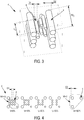
- the figure 3 shows a perspective view of a wear indicator according to the invention.
- the wear indicator 6 comprises a first family of wear cavities 8, intended to quantify the rate of wear of the circumferential rib at any time during the life of the tire, each wear cavity 8 being a cylinder depth P1 i having an emerging surface inscribed in a circle of diameter D1.
- the wear indicator 6 comprises a second family of positioning cavities 9, intended to identify the axial positioning of the wear indicator, that is to say its positioning in the axial width of the tread, each wear cavity 9 being a depth cylinder P2 j having an emerging surface inscribed in a circle of diameter D2.
- the figure 4 shows a top view of a wear indicator according to the invention, at different wear rates.
- the wear rate U is equal to 1-HO / HR, HR being the admissible residual height: by convention, this maximum wear rate is taken equal to 100%.
- the wear indicator 6 comprises ten wear cavities 8 and three positioning cavities 9.
- a wear indicator 6 For a wear rate equal to 10%, a first wear cavity C1 1 , having a depth P1 1 equal to 0.1 ⁇ (H0-HR), has been completely worn and is no longer visible on the running surface: the wear indicator 6 then comprises nine wear cavities 8 and three positioning cavities 9. For a wear rate equal to 20%, a second wear cavity C1 2 , having a depth P1 2 equal to 0.2 ⁇ (H0-HR), has been completely worn and is no longer visible on the surface. bearing: the wear indicator 6 then comprises eight wear cavities 8 and three positioning cavities 9.
- a third wear cavity C1 3 having a depth P1 3 equal to 0.3 ⁇ (H0-HR)
- the wear indicator 6 then comprises seven cavities d 'wear 8 and three positioning cavities 9.
- all the wear cavities 8 of the wear indicator 6 have been completely worn: only the three cavities of the positioning 9 of which the respective depths P2 j , j varying from 1 to 3, are strictly greater than H0-HR.
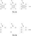
- the figure 5A represents, for a new tire with zero wear rate, three wear indicators (61, 62, 63) respectively positioned in the middle circumferential rib 42 and the circumferential shoulder ribs (41, 43), the said circumferential ribs not being represented on the figure 5A .
- the three wear indicators (61, 62, 63) have the same number N1 of wear cavities and different numbers N2 of positioning cavities, making it possible to differentiate them from one another and to identify their belonging to a given circumferential rib .
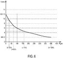
- the figure 6 shows the variation of the height H of a circumferential rib as a function of the number of landings made N LPT (LPT meaning “Landings Per Tread”).
- N LPT Low-power Polyurethane
- the height H of the circumferential rib varies from an initial value equal to 12 mm, for a new tire at zero wear rate, when no landing has yet been made, up to an admissible residual value HR equal to 2 mm, for a tire totally worn with a wear rate equal to 100%, after 400 landings.
- the change in height H as a function of the number of landings made N LPT is not linear.
- wear rates U equal to 25%, 50% and 75% correspond respectively, in the present case, to 30, 65 and 160 landings.
- the curve of evolution of the height H of a given circumferential rib as a function of the number of landings made N LPT , or wear curve is determined during the first tire life cycle, ranging from a new tire to a completely worn tire, by means of wear indicators positioned in said circumferential rib.
- This wear curve thus determined for a circumferential rib of a given tire on a given aircraft, can be used to predict the wear potential remaining of the tire at each observation of the tire. This makes it possible to define when the replacement of the tire will be necessary and to provide for maintenance operations in order to reduce the downtime of the airplane.
- the invention has been more particularly studied in the case of an airplane tire of size 46x17R20, intended to equip the main landing gear of an airliner.
- the inflation pressure is 15.3 bars, the static load 21 tonnes and the maximum speed 360 km / h.
- three circumferential ribs including a median circumferential rib and two circumferential shoulder ribs, each include six wear indicators equidistant along the circumference of the tire, that is to say distributed every 60 °.
- Any wear indicator of the middle circumferential rib is a pattern of 13 cylindrical cavities, made up of 10 wear cavities, 9 of which are positioned at the center and one at the periphery of the pattern, and of 3 positioning cavities, positioned on the periphery of the pattern.
- Any wear indicator of a second circumferential shoulder rib, corresponding to the innermost circumferential rib, when the tire is mounted on the landing gear is a pattern of 15 cylindrical cavities, made up of 10 cavities of wear, including 9 positioned at the center and one at the periphery of the pattern, and 5 positioning cavities, positioned at the periphery of the pattern.
- the N1 10 wear cavities C1 i , i varying from 1 to 10, have depths P1 i respectively equal to i ⁇ (H0-HR), corresponding to wear rates varying between 10% and 100% in steps of 10%. They also have circular opening surfaces with a diameter of 2 mm.
- the N2 positioning cavities C2 j , j varying from 1 to N2 have P2 j depths all equal to 1.2 ⁇ (H0-HR), corresponding to a wear rate equal to 120%. They also have circular opening surfaces with a diameter of 4 mm. This configuration corresponds to the wear indicators described in the figures 5A and 5B .
Landscapes
- Engineering & Computer Science (AREA)
- Mechanical Engineering (AREA)
- Tires In General (AREA)
- Aviation & Aerospace Engineering (AREA)
Claims (9)
- Flugzeugreifen (1) umfassend einen Laufstreifen (2), der dazu bestimmt ist, über eine Lauffläche (3) mit einem Boden in Kontakt zu treten:- der Laufstreifen (2) umfassend mindestens drei Umfangsrippen (4), die durch mindestens eine Umfangsfurche (5) axial voneinander getrennt sind,- mindestens ein Umfangsrippe (4) aufweisend eine Anfangshöhe H0, die an dem Reifen im Neuzustand gemessen wird, und die dazu bestimmt ist, bis zu einer zulässigen Resthöhe HR abgenutzt zu werden,- die mindestens eine Umfangsrippe (4) umfassend mindestens einen Abnutzungsanzeiger (6),- der Abnutzungsanzeiger (6) umfassend N zylindrische Hohlräume (7), die in der Lauffläche (3) münden und bezogen aufeinander unabhängig sind,dadurch gekennzeichnet, dass die N Hohlräume (7) des Abnutzungsanzeigers (6) in eine erste Familie aus N1 Abnutzungshohlräumen C1i (8) mit jeweiligen Anfangstiefen P1i, die paarweise gesondert und gleich i∗(H0-HR)/N1 sind, wobei i eine Ganzzahl ist, die von 1 bis N1 variiert, und in eine zweite Familie aus N2 Positionierungshohlräumen C2j (9) aufgeteilt sind, wobei j eine Ganzzahl ist, die von 1 bis N2 variiert, jeder Positionierungshohlraum C2j aufweisend eine Anfangstiefe P2j, die streng größer als (H0-HR) ist, so dass nur die N2 Positionierungshohlräume C2j (9) in der Lauffläche (3) münden, wenn die zulässige Resthöhe HR der Umfangsrippe (4) erreicht ist.
- Flugzeugreifen (1) nach Anspruch 1, wobei die Anzahl N1 von Abnutzungshohlräumen C1i (8) mindestens gleich 1 und höchstens gleich 10 ist.
- Flugzeugreifen (1) nach einem der Ansprüche 1 oder 2, wobei die Anzahl N2 von Positionierungshohlräumen C2j (9) mindestens gleich 1 und höchstens gleich 5 ist.
- Flugzeugreifen (1) nach einem der Ansprüche 1 bis 3, wobei jeder Hohlraum (7) auf der Lauffläche (3) eine Mündungsfläche aufweist, die in einem Kreis mit dem Durchmesser D mindestens gleich 2 mm und höchstens gleich 10 mm liegt.
- Flugzeugreifen (1) nach einem der Ansprüche 1 bis 4, wobei alle Abnutzungshohlräume C1i (8) auf der Lauffläche (3) eine Mündungsfläche aufweisen, die in einem Kreis mit identischem Durchmesser D1 liegt.
- Flugzeugreifen (1) nach einem der Ansprüche 1 bis 5, wobei alle Positionierungshohlräume C2j (9) auf der Lauffläche (3) eine Mündungsfläche aufweisen, die in einem Kreis mit identischem Durchmesser D2 liegt.
- Flugzeugreifen (1) nach einem der Ansprüche 1 bis 6, wobei der Laufstreifen (2) zwei Schulter-Umfangsrippen (41, 43) und eine Mittel-Umfangsrippe (42) umfasst, jeweils umfassend mindestens einen Abnutzungsanzeiger (61, 62, 63) mit derselben Anzahl N1 von Abnutzungshohlräumen C1i und einer verschiedenen Anzahl N2 von Positionierungshohlräumen C2j, so dass die Gesamtzahl N=N1+N2 von Hohlräumen für jede der zwei Schulter-Umfangsrippen (41, 43) und der Mittel-Umfangsrippe (42) verschieden ist.
- Flugzeugreifen (1) nach einem der Ansprüche 1 bis 7, wobei der Laufstreifen (2) zwei Schulter-Umfangsrippen (41, 43) und eine Mittel-Umfangsrippe (42) umfasst, jeweils umfassend mindestens drei Abnutzungsanzeiger (61, 62, 63), die über den Umfang der Umfangsrippe verteilt sind, die für jede Umfangsrippe zueinander identisch sind und von einer Umfangsrippe zur anderen dieselbe Anzahl N1 von Abnutzungshohlräumen C1i und eine verschiedene Anzahl N2 von Positionierungshohlräumen C2j aufweisen.
- Flugzeugreifen (1) nach einem der Ansprüche 7 oder 8, wobei der jeweilige mindestens eine Abnutzungsanzeiger (61, 62, 63) der zwei Schulter-Umfangsrippen (41, 43) und der Mittel-Umfangsrippe (42) in Umfangsrichtung in einem Umfangs-Winkelabschnitt von höchstens gleich 20° einander positioniert sind.
Applications Claiming Priority (2)
| Application Number | Priority Date | Filing Date | Title |
|---|---|---|---|
| FR1662816A FR3060457A1 (fr) | 2016-12-20 | 2016-12-20 | Indicateur d'usure de bande de roulement de pneumatique pour avion |
| PCT/FR2017/053641 WO2018115674A1 (fr) | 2016-12-20 | 2017-12-18 | Indicateur d'usure de bande de roulement de pneumatique pour avion |
Publications (2)
| Publication Number | Publication Date |
|---|---|
| EP3558717A1 EP3558717A1 (de) | 2019-10-30 |
| EP3558717B1 true EP3558717B1 (de) | 2020-11-18 |
Family
ID=58162860
Family Applications (1)
| Application Number | Title | Priority Date | Filing Date |
|---|---|---|---|
| EP17828956.7A Active EP3558717B1 (de) | 2016-12-20 | 2017-12-18 | Flugzeugreifenlaufflächenverschleissanzeiger |
Country Status (5)
| Country | Link |
|---|---|
| US (1) | US11220139B2 (de) |
| EP (1) | EP3558717B1 (de) |
| CN (1) | CN110049885B (de) |
| FR (1) | FR3060457A1 (de) |
| WO (1) | WO2018115674A1 (de) |
Families Citing this family (5)
| Publication number | Priority date | Publication date | Assignee | Title |
|---|---|---|---|---|
| EP3225428B1 (de) * | 2016-04-01 | 2020-05-27 | Nokian Renkaat Oyj | Gussform zur herstellung eines verschleissanzeigers in einem luftreifen und luftreifen mit dem verschleissanzeiger |
| FR3089862B3 (fr) * | 2018-12-18 | 2020-11-27 | Michelin & Cie | Pneumatique pour moto |
| FR3096950B1 (fr) * | 2019-06-05 | 2022-07-22 | Newtl | Dispositif de surveillance de l’usure d’un flasque de galet |
| IT202200013540A1 (it) * | 2022-06-27 | 2023-12-27 | Wittur Holding Gmbh | Rotella per operatore porta di un ascensore |
| AU2024345694A1 (en) * | 2023-09-21 | 2025-06-12 | Omni United (S) Pte Ltd. | Tire tread depth indicator and method of making and using |
Family Cites Families (19)
| Publication number | Priority date | Publication date | Assignee | Title |
|---|---|---|---|---|
| FR1480472A (fr) | 1966-05-10 | 1967-05-12 | Pneumatiques avec signalisation visible positive ou négative incorporée pour indiquer qu'a été atteinte l'épaisseur limite de sécurité des bandes de roulement | |
| EP0250113A3 (de) * | 1986-06-18 | 1988-09-28 | General Tire Inc. | Reifen mit verschleissanzeigenden Rillen |
| DE4122648A1 (de) * | 1991-07-09 | 1993-01-14 | Dubbel Siegfried Gottfried Joh | Kraftfahrzeugreifen |
| JPH08104113A (ja) * | 1994-09-30 | 1996-04-23 | Hiromoto Morishita | 自動車のタイヤ |
| CN2480175Y (zh) * | 2001-06-01 | 2002-03-06 | 何剑波 | 一种具有磨耗显示层的轮胎 |
| US7011126B2 (en) | 2003-10-17 | 2006-03-14 | The Goodyear Tire & Rubber Company | Progressive tire tread wear indicator |
| US7509834B2 (en) * | 2004-12-15 | 2009-03-31 | International Business Machines Corporation | Monitoring of wearing surface layer thickness |
| JP2006232152A (ja) * | 2005-02-25 | 2006-09-07 | Bridgestone Corp | タイヤ |
| FR2883508B1 (fr) * | 2005-03-25 | 2007-05-18 | Michelin Soc Tech | Indicateur d'usure pour pneumatique |
| FR2917668B1 (fr) * | 2008-07-31 | 2010-02-26 | Michelin Soc Tech | Indicateur d'usure pour pneumatique |
| FR2976852B1 (fr) * | 2011-06-23 | 2016-12-23 | Soc De Tech Michelin | Pneumatique muni de canaux sonores |
| CN102837566A (zh) * | 2012-10-08 | 2012-12-26 | 双钱集团(如皋)轮胎有限公司 | 一种轮胎花纹深度磨损标识、读取方法 |
| CN202911471U (zh) * | 2012-10-08 | 2013-05-01 | 双钱集团(如皋)轮胎有限公司 | 一种轮胎花纹深度磨损标识结构 |
| ES2841743T3 (es) * | 2013-09-10 | 2021-07-09 | Cooper Tire & Rubber Co | Indicador visual de desgaste |
| DE102014003985A1 (de) | 2014-03-19 | 2015-09-24 | Man Truck & Bus Ag | Verschleißteil mit einem Verschleißindikator und System zur Verschleißprüfung |
| JP6557996B2 (ja) * | 2015-03-04 | 2019-08-14 | 横浜ゴム株式会社 | 空気入りタイヤ |
| CN204586376U (zh) | 2015-04-20 | 2015-08-26 | 特拓(青岛)轮胎技术有限公司 | 一种新型花瓣状轮胎胎面磨耗深度标识 |
| EP3225428B1 (de) * | 2016-04-01 | 2020-05-27 | Nokian Renkaat Oyj | Gussform zur herstellung eines verschleissanzeigers in einem luftreifen und luftreifen mit dem verschleissanzeiger |
| FR3060821A1 (fr) * | 2016-12-20 | 2018-06-22 | Compagnie Generale Des Etablissements Michelin | Procede de determination de l'etat d'usure d'un pneumatique pour avion |
-
2016
- 2016-12-20 FR FR1662816A patent/FR3060457A1/fr not_active Ceased
-
2017
- 2017-12-18 WO PCT/FR2017/053641 patent/WO2018115674A1/fr not_active Ceased
- 2017-12-18 CN CN201780076193.0A patent/CN110049885B/zh active Active
- 2017-12-18 US US16/471,408 patent/US11220139B2/en active Active
- 2017-12-18 EP EP17828956.7A patent/EP3558717B1/de active Active
Non-Patent Citations (1)
| Title |
|---|
| None * |
Also Published As
| Publication number | Publication date |
|---|---|
| WO2018115674A1 (fr) | 2018-06-28 |
| US11220139B2 (en) | 2022-01-11 |
| CN110049885B (zh) | 2021-04-09 |
| US20190375494A1 (en) | 2019-12-12 |
| CN110049885A (zh) | 2019-07-23 |
| FR3060457A1 (fr) | 2018-06-22 |
| EP3558717A1 (de) | 2019-10-30 |
Similar Documents
| Publication | Publication Date | Title |
|---|---|---|
| WO2018115674A1 (fr) | Indicateur d'usure de bande de roulement de pneumatique pour avion | |
| EP3558718A1 (de) | Verfahren zur bestimmung des verschleisszustands eines flugzeugreifens | |
| EP1705034B1 (de) | Abriebindikator für Luftreifen | |
| EP2694302B1 (de) | Lauffläche mit mindestens einer wellenförmigen nut und herstellungsverfahren dafür | |
| EP3592577B1 (de) | Reifen mit einer struktur an einer seitenwand | |
| EP2794300B1 (de) | Krone für einen flugzeugreifen | |
| EP3592576B1 (de) | Reifen mit verschleissanzeiger | |
| EP3303007B1 (de) | Verbesserte reifenlauffläche | |
| WO2014170283A1 (fr) | Bande de roulement de pneu de genie civil a taux de creux variable | |
| EP2794299B1 (de) | Reifen für flugzeugreifen | |
| FR3128666A1 (fr) | Pneumatique pour un véhicule poids lourd avec bande de roulement à sculpture complexe | |
| EP2307209A1 (de) | Reifenverschleissanzeiger | |
| EP3894239B1 (de) | Mit einer farbigen markierung und mit einer textur auf einer flanke versehener reifen | |
| EP2825399A1 (de) | Dicke lauffläche für reifen ziviler baufahrzeuge | |
| EP4313635B1 (de) | Reifen für einen stadtbus mit seitenwandverschleissanzeige mit besserer sichtbarkeit | |
| EP3898282B1 (de) | Motorradreifen | |
| EP3619058B1 (de) | Luftreifen mit explizitem verschleissanzeiger | |
| WO2025219106A1 (fr) | Pneumatique comprenant un élément de surface texturé à fort contraste | |
| EP3204241B1 (de) | Gürtellage für einen flugzeugreifen | |
| WO2017060175A1 (fr) | Pneumatique a carcasse radiale ou croisee |
Legal Events
| Date | Code | Title | Description |
|---|---|---|---|
| STAA | Information on the status of an ep patent application or granted ep patent |
Free format text: STATUS: UNKNOWN |
|
| STAA | Information on the status of an ep patent application or granted ep patent |
Free format text: STATUS: THE INTERNATIONAL PUBLICATION HAS BEEN MADE |
|
| PUAI | Public reference made under article 153(3) epc to a published international application that has entered the european phase |
Free format text: ORIGINAL CODE: 0009012 |
|
| STAA | Information on the status of an ep patent application or granted ep patent |
Free format text: STATUS: REQUEST FOR EXAMINATION WAS MADE |
|
| 17P | Request for examination filed |
Effective date: 20190722 |
|
| AK | Designated contracting states |
Kind code of ref document: A1 Designated state(s): AL AT BE BG CH CY CZ DE DK EE ES FI FR GB GR HR HU IE IS IT LI LT LU LV MC MK MT NL NO PL PT RO RS SE SI SK SM TR |
|
| AX | Request for extension of the european patent |
Extension state: BA ME |
|
| DAV | Request for validation of the european patent (deleted) | ||
| DAX | Request for extension of the european patent (deleted) | ||
| REG | Reference to a national code |
Ref country code: DE Ref legal event code: R079 Ref document number: 602017027978 Country of ref document: DE Free format text: PREVIOUS MAIN CLASS: B60C0011240000 Ipc: B60C0011030000 |
|
| RIC1 | Information provided on ipc code assigned before grant |
Ipc: B60C 11/04 20060101ALI20200430BHEP Ipc: B60C 11/03 20060101AFI20200430BHEP Ipc: B60C 11/24 20060101ALI20200430BHEP |
|
| GRAP | Despatch of communication of intention to grant a patent |
Free format text: ORIGINAL CODE: EPIDOSNIGR1 |
|
| STAA | Information on the status of an ep patent application or granted ep patent |
Free format text: STATUS: GRANT OF PATENT IS INTENDED |
|
| INTG | Intention to grant announced |
Effective date: 20200616 |
|
| GRAS | Grant fee paid |
Free format text: ORIGINAL CODE: EPIDOSNIGR3 |
|
| GRAA | (expected) grant |
Free format text: ORIGINAL CODE: 0009210 |
|
| STAA | Information on the status of an ep patent application or granted ep patent |
Free format text: STATUS: THE PATENT HAS BEEN GRANTED |
|
| AK | Designated contracting states |
Kind code of ref document: B1 Designated state(s): AL AT BE BG CH CY CZ DE DK EE ES FI FR GB GR HR HU IE IS IT LI LT LU LV MC MK MT NL NO PL PT RO RS SE SI SK SM TR |
|
| REG | Reference to a national code |
Ref country code: GB Ref legal event code: FG4D Free format text: NOT ENGLISH |
|
| REG | Reference to a national code |
Ref country code: CH Ref legal event code: EP |
|
| REG | Reference to a national code |
Ref country code: DE Ref legal event code: R096 Ref document number: 602017027978 Country of ref document: DE |
|
| REG | Reference to a national code |
Ref country code: IE Ref legal event code: FG4D Free format text: LANGUAGE OF EP DOCUMENT: FRENCH |
|
| REG | Reference to a national code |
Ref country code: AT Ref legal event code: REF Ref document number: 1335361 Country of ref document: AT Kind code of ref document: T Effective date: 20201215 |
|
| REG | Reference to a national code |
Ref country code: AT Ref legal event code: MK05 Ref document number: 1335361 Country of ref document: AT Kind code of ref document: T Effective date: 20201118 |
|
| REG | Reference to a national code |
Ref country code: NL Ref legal event code: MP Effective date: 20201118 |
|
| PG25 | Lapsed in a contracting state [announced via postgrant information from national office to epo] |
Ref country code: GR Free format text: LAPSE BECAUSE OF FAILURE TO SUBMIT A TRANSLATION OF THE DESCRIPTION OR TO PAY THE FEE WITHIN THE PRESCRIBED TIME-LIMIT Effective date: 20210219 Ref country code: NO Free format text: LAPSE BECAUSE OF FAILURE TO SUBMIT A TRANSLATION OF THE DESCRIPTION OR TO PAY THE FEE WITHIN THE PRESCRIBED TIME-LIMIT Effective date: 20210218 Ref country code: PT Free format text: LAPSE BECAUSE OF FAILURE TO SUBMIT A TRANSLATION OF THE DESCRIPTION OR TO PAY THE FEE WITHIN THE PRESCRIBED TIME-LIMIT Effective date: 20210318 Ref country code: RS Free format text: LAPSE BECAUSE OF FAILURE TO SUBMIT A TRANSLATION OF THE DESCRIPTION OR TO PAY THE FEE WITHIN THE PRESCRIBED TIME-LIMIT Effective date: 20201118 Ref country code: FI Free format text: LAPSE BECAUSE OF FAILURE TO SUBMIT A TRANSLATION OF THE DESCRIPTION OR TO PAY THE FEE WITHIN THE PRESCRIBED TIME-LIMIT Effective date: 20201118 |
|
| PG25 | Lapsed in a contracting state [announced via postgrant information from national office to epo] |
Ref country code: AT Free format text: LAPSE BECAUSE OF FAILURE TO SUBMIT A TRANSLATION OF THE DESCRIPTION OR TO PAY THE FEE WITHIN THE PRESCRIBED TIME-LIMIT Effective date: 20201118 Ref country code: BG Free format text: LAPSE BECAUSE OF FAILURE TO SUBMIT A TRANSLATION OF THE DESCRIPTION OR TO PAY THE FEE WITHIN THE PRESCRIBED TIME-LIMIT Effective date: 20210218 Ref country code: LV Free format text: LAPSE BECAUSE OF FAILURE TO SUBMIT A TRANSLATION OF THE DESCRIPTION OR TO PAY THE FEE WITHIN THE PRESCRIBED TIME-LIMIT Effective date: 20201118 Ref country code: PL Free format text: LAPSE BECAUSE OF FAILURE TO SUBMIT A TRANSLATION OF THE DESCRIPTION OR TO PAY THE FEE WITHIN THE PRESCRIBED TIME-LIMIT Effective date: 20201118 Ref country code: IS Free format text: LAPSE BECAUSE OF FAILURE TO SUBMIT A TRANSLATION OF THE DESCRIPTION OR TO PAY THE FEE WITHIN THE PRESCRIBED TIME-LIMIT Effective date: 20210318 Ref country code: SE Free format text: LAPSE BECAUSE OF FAILURE TO SUBMIT A TRANSLATION OF THE DESCRIPTION OR TO PAY THE FEE WITHIN THE PRESCRIBED TIME-LIMIT Effective date: 20201118 |
|
| REG | Reference to a national code |
Ref country code: LT Ref legal event code: MG9D |
|
| PG25 | Lapsed in a contracting state [announced via postgrant information from national office to epo] |
Ref country code: HR Free format text: LAPSE BECAUSE OF FAILURE TO SUBMIT A TRANSLATION OF THE DESCRIPTION OR TO PAY THE FEE WITHIN THE PRESCRIBED TIME-LIMIT Effective date: 20201118 |
|
| REG | Reference to a national code |
Ref country code: DE Ref legal event code: R119 Ref document number: 602017027978 Country of ref document: DE |
|
| PG25 | Lapsed in a contracting state [announced via postgrant information from national office to epo] |
Ref country code: EE Free format text: LAPSE BECAUSE OF FAILURE TO SUBMIT A TRANSLATION OF THE DESCRIPTION OR TO PAY THE FEE WITHIN THE PRESCRIBED TIME-LIMIT Effective date: 20201118 Ref country code: CZ Free format text: LAPSE BECAUSE OF FAILURE TO SUBMIT A TRANSLATION OF THE DESCRIPTION OR TO PAY THE FEE WITHIN THE PRESCRIBED TIME-LIMIT Effective date: 20201118 Ref country code: LT Free format text: LAPSE BECAUSE OF FAILURE TO SUBMIT A TRANSLATION OF THE DESCRIPTION OR TO PAY THE FEE WITHIN THE PRESCRIBED TIME-LIMIT Effective date: 20201118 Ref country code: SM Free format text: LAPSE BECAUSE OF FAILURE TO SUBMIT A TRANSLATION OF THE DESCRIPTION OR TO PAY THE FEE WITHIN THE PRESCRIBED TIME-LIMIT Effective date: 20201118 Ref country code: SK Free format text: LAPSE BECAUSE OF FAILURE TO SUBMIT A TRANSLATION OF THE DESCRIPTION OR TO PAY THE FEE WITHIN THE PRESCRIBED TIME-LIMIT Effective date: 20201118 Ref country code: RO Free format text: LAPSE BECAUSE OF FAILURE TO SUBMIT A TRANSLATION OF THE DESCRIPTION OR TO PAY THE FEE WITHIN THE PRESCRIBED TIME-LIMIT Effective date: 20201118 |
|
| REG | Reference to a national code |
Ref country code: CH Ref legal event code: PL |
|
| PG25 | Lapsed in a contracting state [announced via postgrant information from national office to epo] |
Ref country code: DK Free format text: LAPSE BECAUSE OF FAILURE TO SUBMIT A TRANSLATION OF THE DESCRIPTION OR TO PAY THE FEE WITHIN THE PRESCRIBED TIME-LIMIT Effective date: 20201118 Ref country code: MC Free format text: LAPSE BECAUSE OF FAILURE TO SUBMIT A TRANSLATION OF THE DESCRIPTION OR TO PAY THE FEE WITHIN THE PRESCRIBED TIME-LIMIT Effective date: 20201118 |
|
| REG | Reference to a national code |
Ref country code: BE Ref legal event code: MM Effective date: 20201231 |
|
| PLBE | No opposition filed within time limit |
Free format text: ORIGINAL CODE: 0009261 |
|
| STAA | Information on the status of an ep patent application or granted ep patent |
Free format text: STATUS: NO OPPOSITION FILED WITHIN TIME LIMIT |
|
| 26N | No opposition filed |
Effective date: 20210819 |
|
| PG25 | Lapsed in a contracting state [announced via postgrant information from national office to epo] |
Ref country code: IT Free format text: LAPSE BECAUSE OF FAILURE TO SUBMIT A TRANSLATION OF THE DESCRIPTION OR TO PAY THE FEE WITHIN THE PRESCRIBED TIME-LIMIT Effective date: 20201118 Ref country code: LU Free format text: LAPSE BECAUSE OF NON-PAYMENT OF DUE FEES Effective date: 20201218 Ref country code: NL Free format text: LAPSE BECAUSE OF FAILURE TO SUBMIT A TRANSLATION OF THE DESCRIPTION OR TO PAY THE FEE WITHIN THE PRESCRIBED TIME-LIMIT Effective date: 20201118 Ref country code: AL Free format text: LAPSE BECAUSE OF FAILURE TO SUBMIT A TRANSLATION OF THE DESCRIPTION OR TO PAY THE FEE WITHIN THE PRESCRIBED TIME-LIMIT Effective date: 20201118 Ref country code: IE Free format text: LAPSE BECAUSE OF NON-PAYMENT OF DUE FEES Effective date: 20201218 |
|
| PG25 | Lapsed in a contracting state [announced via postgrant information from national office to epo] |
Ref country code: SI Free format text: LAPSE BECAUSE OF FAILURE TO SUBMIT A TRANSLATION OF THE DESCRIPTION OR TO PAY THE FEE WITHIN THE PRESCRIBED TIME-LIMIT Effective date: 20201118 Ref country code: CH Free format text: LAPSE BECAUSE OF NON-PAYMENT OF DUE FEES Effective date: 20201231 Ref country code: DE Free format text: LAPSE BECAUSE OF NON-PAYMENT OF DUE FEES Effective date: 20210701 Ref country code: LI Free format text: LAPSE BECAUSE OF NON-PAYMENT OF DUE FEES Effective date: 20201231 |
|
| PG25 | Lapsed in a contracting state [announced via postgrant information from national office to epo] |
Ref country code: ES Free format text: LAPSE BECAUSE OF FAILURE TO SUBMIT A TRANSLATION OF THE DESCRIPTION OR TO PAY THE FEE WITHIN THE PRESCRIBED TIME-LIMIT Effective date: 20201118 |
|
| PG25 | Lapsed in a contracting state [announced via postgrant information from national office to epo] |
Ref country code: IS Free format text: LAPSE BECAUSE OF FAILURE TO SUBMIT A TRANSLATION OF THE DESCRIPTION OR TO PAY THE FEE WITHIN THE PRESCRIBED TIME-LIMIT Effective date: 20210318 Ref country code: TR Free format text: LAPSE BECAUSE OF FAILURE TO SUBMIT A TRANSLATION OF THE DESCRIPTION OR TO PAY THE FEE WITHIN THE PRESCRIBED TIME-LIMIT Effective date: 20201118 Ref country code: MT Free format text: LAPSE BECAUSE OF FAILURE TO SUBMIT A TRANSLATION OF THE DESCRIPTION OR TO PAY THE FEE WITHIN THE PRESCRIBED TIME-LIMIT Effective date: 20201118 Ref country code: CY Free format text: LAPSE BECAUSE OF FAILURE TO SUBMIT A TRANSLATION OF THE DESCRIPTION OR TO PAY THE FEE WITHIN THE PRESCRIBED TIME-LIMIT Effective date: 20201118 |
|
| PG25 | Lapsed in a contracting state [announced via postgrant information from national office to epo] |
Ref country code: MK Free format text: LAPSE BECAUSE OF FAILURE TO SUBMIT A TRANSLATION OF THE DESCRIPTION OR TO PAY THE FEE WITHIN THE PRESCRIBED TIME-LIMIT Effective date: 20201118 |
|
| PG25 | Lapsed in a contracting state [announced via postgrant information from national office to epo] |
Ref country code: BE Free format text: LAPSE BECAUSE OF NON-PAYMENT OF DUE FEES Effective date: 20201231 |
|
| GBPC | Gb: european patent ceased through non-payment of renewal fee |
Effective date: 20211218 |
|
| PG25 | Lapsed in a contracting state [announced via postgrant information from national office to epo] |
Ref country code: GB Free format text: LAPSE BECAUSE OF NON-PAYMENT OF DUE FEES Effective date: 20211218 |
|
| PGFP | Annual fee paid to national office [announced via postgrant information from national office to epo] |
Ref country code: FR Payment date: 20251229 Year of fee payment: 9 |