EP3558622B1 - Verfahren zum spritzgiessen von innen hohlen teilen - Google Patents
Verfahren zum spritzgiessen von innen hohlen teilen Download PDFInfo
- Publication number
- EP3558622B1 EP3558622B1 EP17825627.7A EP17825627A EP3558622B1 EP 3558622 B1 EP3558622 B1 EP 3558622B1 EP 17825627 A EP17825627 A EP 17825627A EP 3558622 B1 EP3558622 B1 EP 3558622B1
- Authority
- EP
- European Patent Office
- Prior art keywords
- nitrogen
- inner space
- valve
- supply
- connecting duct
- Prior art date
- Legal status (The legal status is an assumption and is not a legal conclusion. Google has not performed a legal analysis and makes no representation as to the accuracy of the status listed.)
- Active
Links
Images


Classifications
-
- B—PERFORMING OPERATIONS; TRANSPORTING
- B29—WORKING OF PLASTICS; WORKING OF SUBSTANCES IN A PLASTIC STATE IN GENERAL
- B29C—SHAPING OR JOINING OF PLASTICS; SHAPING OF MATERIAL IN A PLASTIC STATE, NOT OTHERWISE PROVIDED FOR; AFTER-TREATMENT OF THE SHAPED PRODUCTS, e.g. REPAIRING
- B29C45/00—Injection moulding, i.e. forcing the required volume of moulding material through a nozzle into a closed mould; Apparatus therefor
- B29C45/17—Component parts, details or accessories; Auxiliary operations
- B29C45/1703—Introducing an auxiliary fluid into the mould
- B29C45/1704—Introducing an auxiliary fluid into the mould the fluid being introduced into the interior of the injected material which is still in a molten state, e.g. for producing hollow articles
- B29C45/1711—Introducing an auxiliary fluid into the mould the fluid being introduced into the interior of the injected material which is still in a molten state, e.g. for producing hollow articles and removing excess material from the mould cavity by the introduced fluid, e.g. to an overflow cavity
-
- B—PERFORMING OPERATIONS; TRANSPORTING
- B29—WORKING OF PLASTICS; WORKING OF SUBSTANCES IN A PLASTIC STATE IN GENERAL
- B29C—SHAPING OR JOINING OF PLASTICS; SHAPING OF MATERIAL IN A PLASTIC STATE, NOT OTHERWISE PROVIDED FOR; AFTER-TREATMENT OF THE SHAPED PRODUCTS, e.g. REPAIRING
- B29C45/00—Injection moulding, i.e. forcing the required volume of moulding material through a nozzle into a closed mould; Apparatus therefor
- B29C45/17—Component parts, details or accessories; Auxiliary operations
- B29C45/1703—Introducing an auxiliary fluid into the mould
- B29C45/1734—Nozzles therefor
-
- B—PERFORMING OPERATIONS; TRANSPORTING
- B29—WORKING OF PLASTICS; WORKING OF SUBSTANCES IN A PLASTIC STATE IN GENERAL
- B29C—SHAPING OR JOINING OF PLASTICS; SHAPING OF MATERIAL IN A PLASTIC STATE, NOT OTHERWISE PROVIDED FOR; AFTER-TREATMENT OF THE SHAPED PRODUCTS, e.g. REPAIRING
- B29C45/00—Injection moulding, i.e. forcing the required volume of moulding material through a nozzle into a closed mould; Apparatus therefor
- B29C45/17—Component parts, details or accessories; Auxiliary operations
- B29C45/1703—Introducing an auxiliary fluid into the mould
- B29C45/1704—Introducing an auxiliary fluid into the mould the fluid being introduced into the interior of the injected material which is still in a molten state, e.g. for producing hollow articles
- B29C2045/1726—Introducing an auxiliary fluid into the mould the fluid being introduced into the interior of the injected material which is still in a molten state, e.g. for producing hollow articles moving the fluid through the hollow using a fluid inlet and a fluid outlet
-
- B—PERFORMING OPERATIONS; TRANSPORTING
- B29—WORKING OF PLASTICS; WORKING OF SUBSTANCES IN A PLASTIC STATE IN GENERAL
- B29C—SHAPING OR JOINING OF PLASTICS; SHAPING OF MATERIAL IN A PLASTIC STATE, NOT OTHERWISE PROVIDED FOR; AFTER-TREATMENT OF THE SHAPED PRODUCTS, e.g. REPAIRING
- B29C45/00—Injection moulding, i.e. forcing the required volume of moulding material through a nozzle into a closed mould; Apparatus therefor
- B29C45/17—Component parts, details or accessories; Auxiliary operations
- B29C45/1703—Introducing an auxiliary fluid into the mould
- B29C45/1704—Introducing an auxiliary fluid into the mould the fluid being introduced into the interior of the injected material which is still in a molten state, e.g. for producing hollow articles
- B29C2045/1729—Introducing an auxiliary fluid into the mould the fluid being introduced into the interior of the injected material which is still in a molten state, e.g. for producing hollow articles fluid venting means
-
- B—PERFORMING OPERATIONS; TRANSPORTING
- B29—WORKING OF PLASTICS; WORKING OF SUBSTANCES IN A PLASTIC STATE IN GENERAL
- B29C—SHAPING OR JOINING OF PLASTICS; SHAPING OF MATERIAL IN A PLASTIC STATE, NOT OTHERWISE PROVIDED FOR; AFTER-TREATMENT OF THE SHAPED PRODUCTS, e.g. REPAIRING
- B29C45/00—Injection moulding, i.e. forcing the required volume of moulding material through a nozzle into a closed mould; Apparatus therefor
- B29C45/17—Component parts, details or accessories; Auxiliary operations
- B29C45/1703—Introducing an auxiliary fluid into the mould
- B29C45/1704—Introducing an auxiliary fluid into the mould the fluid being introduced into the interior of the injected material which is still in a molten state, e.g. for producing hollow articles
- B29C2045/173—Introducing an auxiliary fluid into the mould the fluid being introduced into the interior of the injected material which is still in a molten state, e.g. for producing hollow articles using a plurality of fluid injection nozzles
-
- B—PERFORMING OPERATIONS; TRANSPORTING
- B29—WORKING OF PLASTICS; WORKING OF SUBSTANCES IN A PLASTIC STATE IN GENERAL
- B29C—SHAPING OR JOINING OF PLASTICS; SHAPING OF MATERIAL IN A PLASTIC STATE, NOT OTHERWISE PROVIDED FOR; AFTER-TREATMENT OF THE SHAPED PRODUCTS, e.g. REPAIRING
- B29C45/00—Injection moulding, i.e. forcing the required volume of moulding material through a nozzle into a closed mould; Apparatus therefor
- B29C45/17—Component parts, details or accessories; Auxiliary operations
- B29C45/1703—Introducing an auxiliary fluid into the mould
- B29C45/1732—Control circuits therefor
-
- B—PERFORMING OPERATIONS; TRANSPORTING
- B29—WORKING OF PLASTICS; WORKING OF SUBSTANCES IN A PLASTIC STATE IN GENERAL
- B29C—SHAPING OR JOINING OF PLASTICS; SHAPING OF MATERIAL IN A PLASTIC STATE, NOT OTHERWISE PROVIDED FOR; AFTER-TREATMENT OF THE SHAPED PRODUCTS, e.g. REPAIRING
- B29C45/00—Injection moulding, i.e. forcing the required volume of moulding material through a nozzle into a closed mould; Apparatus therefor
- B29C45/17—Component parts, details or accessories; Auxiliary operations
- B29C45/26—Moulds
- B29C45/37—Mould cavity walls, i.e. the inner surface forming the mould cavity, e.g. linings
Definitions
- the present invention regards a method for the injection molding of internally hollow parts.
- This method provides for the injection of a thermoplastic melt from an injection unit along a flow path in an inner space of a mold, then the injection of a fluid in the plastic material still at the softened state, in a manner such that the plastic material is pressed against the walls of the inner space of the mold, then the cooling of the plastic material until a rigid part is formed, and finally the removal of the part from the inner space of the mold.
- US 6713014 describes a process which is deemed the closest technique.
- the inner space of the mold is not completely filled; in addition, the fluid injected in the inner space is a liquid with high thermal capacity, while a portion of the still-softened plastic material is moved from the inner space of the mold to a separate secondary compartment.
- the flow of the thermoplastic material from the inner space of the mold into the secondary cavity is controlled by means of a valve which is closed and opened according to the established timing.
- the forming of the cavity inside the part can be achieved with a fluid which can be water or a gas under pressure, preferably nitrogen.
- nitrogen which constitutes air, involves expenses for its separation and for its maintenance at low temperature.
- DE 19505633 describes a process for making hollow parts of thermoplastic material which provides for the injection of the melt in the inner space of a mold and the simultaneous or successive injection of a pressurized fluid through one or more nozzles. Following the cooling, the fluid is released through one or more pressure-release nozzles separated from the fluid-injection nozzles.
- the fluid preferably nitrogen, can be collected in a container and reused.
- US 5 798 080 A discloses the preamble of claim 1.
- One object of the present finding is to reduce the quantity of pressurized nitrogen to a minimum, in order to reduce the costs of injection molding assisted by pressurized gas.
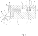
- Figures 1 to 6 are schematic views of an apparatus which employs the method for the injection molding of internally hollow parts according to the present invention.
- an apparatus comprising a mold consisting of a matrix 1 and of a cooperating punch 2, both of which delimit an inner space 3 which has the shape of the molded part indicated with P in figure 6 .
- the inner space 3 communicates on one side with a nozzle 4 for the injection of thermoplastic material F and with a pressurized gas supplying pipe 5, i.e. nitrogen N from a tank of nitrogen and air A from an air tank.
- the tanks are not shown in the figures.
- the pipe 5 has a check valve, not shown, in its convergence with the inner space 3. Outside the mold, an air supply duct 11 converges into the pipe 5.
- a valve 6 for supplying nitrogen is inserted, while on the duct 11 a valve 12 for supplying air is inserted.
- connecting duct 7 which places the inner space 3 in communication with a secondary compartment 8 or created well, such as the inner space 3, between the matrix 1 and the punch 2.
- a valve 9 acts on the connecting duct 7 for the closure and opening thereof, and a perforating element 10 penetrates into the connecting duct 7.
- the method according to the invention comprises the injection in the inner space 3 ( figure 1 ), the opening of the connecting duct 7 ( figure 2 ), the supply of nitrogen in the inner space 3 for the formation of a cavity 13 in the part being molded ( figure 3 ), the perforation of the part being molded in the section of the connecting duct 7 ( figure 4 ), the venting of the cavity 13 created in the part being molded ( figure 5 ), and the removal of the molded part P ( figure 6 ).
- thermoplastic material F in the inner space 3 is activated, between the matrix 1 and the punch 2.
- the valve 6 for nitrogen and the valve 12 for air are closed.
- thermoplastic material after having completely occupied the inner space 3, passes through the connecting duct 7, into the secondary compartment 8.
- the valve 6 is opened and pressurized nitrogen is made to flow through the supply pipe 5; such pressurized nitrogen in the inner space 3 pushes the material still in the softened state towards the walls of the inner space 3 and into the connecting duct 7 up to the compartment 8.
- This step also called emptying, leads to the formation of the cavity 13 inside the part P being molded.
- the supply of pressurized nitrogen N is closed by means of the valve 6, and a perforation is made in the hollow thermoplastic material situated in the connecting duct 7.
- the perforation is made by means of the perforating element 10 which allows the outflow of the pressurized nitrogen through a venting channel 14, with consequent possible recovery of the used nitrogen.
- the venting occurs via pressure difference since the gas supply pipe is inactive, given that the valve 6 for the nitrogen and the valve 12 for the air are closed.
- the air valve 12 is closed, while the valve 6 of the nitrogen is closed and the valve 9 of the connecting duct is opened.
- the extraction of the molded part P is shown in side view in figure 6 .
- the punch 2 is moved away from the matrix 1.
- the gas supply is deactivated, and the supply of the thermoplastic melt is also deactivated.
Landscapes
- Engineering & Computer Science (AREA)
- Manufacturing & Machinery (AREA)
- Mechanical Engineering (AREA)
- Injection Moulding Of Plastics Or The Like (AREA)
- Moulds For Moulding Plastics Or The Like (AREA)
- Blow-Moulding Or Thermoforming Of Plastics Or The Like (AREA)
Claims (2)
- Verfahren zum Spritzgießen von innen hohlen Teilen (P) mittels einer Vorrichtung, die eine Form, die aus einer Matrix (1) und einem damit zusammenwirkenden Stempel (2) besteht, die beide einen Innenraum (3) begrenzen, der auf einer Seite mit einer Düse (4) zum Einspritzen von Schmelze (F) aus thermoplastischem Material und mit einer Druckgaszufuhrleitung (5) in Verbindung steht, gesteuert durch ein erstes Ventil (6) zum Zuführen von Stickstoff (N), und auf der anderen Seite mit einer Verbindungsleitung (7), die den Innenraum (3) mit einem sekundären Fach (8) in Verbindung bringt, ein zweites Ventil (9), das auf die Verbindungsleitung (7) wirkt, um diese zu schließen und zu öffnen, und ein Perforierungselement (10), das einen Teil (P) in der Verbindungsleitung (7) perforiert, aufweist, wobei das Verfahren die folgenden Schritte aufweist:a) Einspritzen von Schmelze (F) aus thermoplastischem Material in den Innenraum (3) zwischen dem Stempel (2) und der Matrix (1),b) Öffnen des zweiten Ventils (9), um den Innenraum (3) mit dem sekundären Fach (8) in Verbindung zu bringen,c) Stoppen des Einspritzens der Schmelze (F) und Öffnen des ersten Ventils (6) zum Zuführen von Stickstoff (N) in den Innenraum (3), um einen Hohlraum (13) zu erzeugen, bis der Stickstoff (N) in das sekundäre Fach (8) gelangt,d) Stoppen der Zufuhr von Stickstoff (N) und Perforieren des geformten Teils (P) im Abschnitt der Verbindungsleitung (7) mittels des Perforierungselements (10) für den Ausfluss von Stickstoff (N) aus der Form,e) Zuführen (A) von Druckluft in die Gasleitung (5) zum Spülen in Richtung der Atmosphäre nach dem Stoppen der Zufuhr von Stickstoff (N) und der Perforation des in dem Abschnitt der Verbindungsleitung (7) geformten Teils (P),
dadurch gekennzeichnet dassf) in Schritt (d) der aus der Form ausströmende Stickstoff (N) aufgefangen wird, und dadurch, dass im selben Schritt (d) das Perforieren des geformten Teils (P) mittels des Perforierungselements (10) gleichzeitig mit dem Stoppen der Zufuhr von Stickstoff (N) erfolgt. - Verfahren gemäß Anspruch 1, wobei die Druckluftzufuhr (A) durch eine Zufuhrleitung (11), die mittels eines dritten Gaszufuhrventils (12) gesteuert wird und in die Gasleitung (5) mündet, erfolgt.
Applications Claiming Priority (2)
| Application Number | Priority Date | Filing Date | Title |
|---|---|---|---|
| IT201600129409 | 2016-12-21 | ||
| PCT/IT2017/050006 WO2018116332A1 (en) | 2016-12-21 | 2017-12-19 | Method for the injection molding of internally hollow parts |
Publications (2)
| Publication Number | Publication Date |
|---|---|
| EP3558622A1 EP3558622A1 (de) | 2019-10-30 |
| EP3558622B1 true EP3558622B1 (de) | 2021-04-28 |
Family
ID=58609819
Family Applications (1)
| Application Number | Title | Priority Date | Filing Date |
|---|---|---|---|
| EP17825627.7A Active EP3558622B1 (de) | 2016-12-21 | 2017-12-19 | Verfahren zum spritzgiessen von innen hohlen teilen |
Country Status (6)
| Country | Link |
|---|---|
| US (1) | US20200016808A1 (de) |
| EP (1) | EP3558622B1 (de) |
| CN (1) | CN110099780A (de) |
| BR (1) | BR112019012502A2 (de) |
| MX (1) | MX2019007164A (de) |
| WO (1) | WO2018116332A1 (de) |
Families Citing this family (1)
| Publication number | Priority date | Publication date | Assignee | Title |
|---|---|---|---|---|
| DE102020133019A1 (de) | 2020-12-10 | 2022-06-15 | Plastic Innovation Gmbh | Verfahren zur Herstellung eines Zweiradrahmens |
Family Cites Families (5)
| Publication number | Priority date | Publication date | Assignee | Title |
|---|---|---|---|---|
| DE19505633A1 (de) * | 1995-02-18 | 1996-08-22 | Battenfeld Gmbh | Verfahren und Vorrichtung zum Herstellen von Kunststoffgegenständen aus thermoplastischem Material |
| JP3376751B2 (ja) * | 1995-03-30 | 2003-02-10 | 豊田合成株式会社 | 樹脂中空体の製造方法及びその製造装置 |
| DE10007994C2 (de) * | 2000-02-22 | 2003-11-13 | Battenfeld Gmbh | Verfahren und Vorrichtung zum Spritzgiessen von mindestens einen Hohlraum aufweisenden Formteilen |
| GB0110263D0 (en) * | 2001-04-26 | 2001-06-20 | Cinpres Ltd | Method and apparatus for injection moulding |
| JP2003127176A (ja) * | 2001-10-29 | 2003-05-08 | Asahi Kasei Corp | ハイサイクル射出成形法 |
-
2017
- 2017-12-19 US US16/470,048 patent/US20200016808A1/en not_active Abandoned
- 2017-12-19 BR BR112019012502A patent/BR112019012502A2/pt not_active Application Discontinuation
- 2017-12-19 WO PCT/IT2017/050006 patent/WO2018116332A1/en not_active Ceased
- 2017-12-19 MX MX2019007164A patent/MX2019007164A/es unknown
- 2017-12-19 CN CN201780079422.4A patent/CN110099780A/zh active Pending
- 2017-12-19 EP EP17825627.7A patent/EP3558622B1/de active Active
Also Published As
| Publication number | Publication date |
|---|---|
| BR112019012502A2 (pt) | 2020-04-14 |
| CN110099780A (zh) | 2019-08-06 |
| WO2018116332A1 (en) | 2018-06-28 |
| MX2019007164A (es) | 2019-08-29 |
| EP3558622A1 (de) | 2019-10-30 |
| US20200016808A1 (en) | 2020-01-16 |
Similar Documents
| Publication | Publication Date | Title |
|---|---|---|
| JP2554529B2 (ja) | 射出成形方法および装置 | |
| JP6216874B2 (ja) | 容器成形の二段階装置および方法 | |
| EP0689499B1 (de) | Verfahren zum herstellen von nadeln | |
| US3837769A (en) | Apparatus for the manufacture of molded articles of foam-forming thermoplastic synthetics | |
| US10737420B2 (en) | Porous insert for nozzle of an injection molding system | |
| AU635235B2 (en) | Injection mold method and apparatus | |
| JP6190057B2 (ja) | 封止ピンを経由する2段階の流れ | |
| JPH01196318A (ja) | 中空体を製造するための流体助力式射出成形法及びシステム | |
| US5824261A (en) | Multi-venting molding apparatus | |
| KR101948963B1 (ko) | 플라스틱 재료의 인젝션 몰딩 방법 | |
| EP3275616B1 (de) | Vorrichtung und verfahren zur luftansaugung in spritzgusswerkzeugen und zur anschliessenden ausstossung von formteilen | |
| US5186884A (en) | Method of injection molding with pressurized fluid assist | |
| US20200016808A1 (en) | Method for the injection molding of internally hollow parts | |
| CN104552767B (zh) | 流体辅助注塑成型的系统 | |
| EP1278623A1 (de) | Verfahren und vorrichtung zum einspritzen von kunststoffmaterial | |
| US7458806B2 (en) | Waste-less injection molding fan gate | |
| JP6954454B2 (ja) | 中空樹脂成形品の製造方法及び中空樹脂成形品の製造装置 | |
| CN104552768B (zh) | 流体辅助注射生产中空制品的方法 | |
| EP2900450B1 (de) | Vorrichtung und verfahren zum spritzgiessen mit entflüftung | |
| US20080111281A1 (en) | Gas assisted injection molding method | |
| AU676281B2 (en) | Method of manufacturing needles | |
| MXPA97005193A (en) | Molding device with multip vents | |
| JP2006007421A (ja) | 中空成形品の成形金型および成形方法 | |
| JPS5919016B2 (ja) | 発泡成形方法及び装置 |
Legal Events
| Date | Code | Title | Description |
|---|---|---|---|
| STAA | Information on the status of an ep patent application or granted ep patent |
Free format text: STATUS: UNKNOWN |
|
| STAA | Information on the status of an ep patent application or granted ep patent |
Free format text: STATUS: THE INTERNATIONAL PUBLICATION HAS BEEN MADE |
|
| PUAI | Public reference made under article 153(3) epc to a published international application that has entered the european phase |
Free format text: ORIGINAL CODE: 0009012 |
|
| STAA | Information on the status of an ep patent application or granted ep patent |
Free format text: STATUS: REQUEST FOR EXAMINATION WAS MADE |
|
| 17P | Request for examination filed |
Effective date: 20190603 |
|
| AK | Designated contracting states |
Kind code of ref document: A1 Designated state(s): AL AT BE BG CH CY CZ DE DK EE ES FI FR GB GR HR HU IE IS IT LI LT LU LV MC MK MT NL NO PL PT RO RS SE SI SK SM TR |
|
| AX | Request for extension of the european patent |
Extension state: BA ME |
|
| DAV | Request for validation of the european patent (deleted) | ||
| GRAP | Despatch of communication of intention to grant a patent |
Free format text: ORIGINAL CODE: EPIDOSNIGR1 |
|
| STAA | Information on the status of an ep patent application or granted ep patent |
Free format text: STATUS: GRANT OF PATENT IS INTENDED |
|
| INTG | Intention to grant announced |
Effective date: 20201211 |
|
| GRAS | Grant fee paid |
Free format text: ORIGINAL CODE: EPIDOSNIGR3 |
|
| GRAA | (expected) grant |
Free format text: ORIGINAL CODE: 0009210 |
|
| STAA | Information on the status of an ep patent application or granted ep patent |
Free format text: STATUS: THE PATENT HAS BEEN GRANTED |
|
| AK | Designated contracting states |
Kind code of ref document: B1 Designated state(s): AL AT BE BG CH CY CZ DE DK EE ES FI FR GB GR HR HU IE IS IT LI LT LU LV MC MK MT NL NO PL PT RO RS SE SI SK SM TR |
|
| AX | Request for extension of the european patent |
Extension state: BA ME |
|
| REG | Reference to a national code |
Ref country code: GB Ref legal event code: FG4D |
|
| REG | Reference to a national code |
Ref country code: CH Ref legal event code: EP |
|
| REG | Reference to a national code |
Ref country code: DE Ref legal event code: R096 Ref document number: 602017037764 Country of ref document: DE |
|
| REG | Reference to a national code |
Ref country code: AT Ref legal event code: REF Ref document number: 1386600 Country of ref document: AT Kind code of ref document: T Effective date: 20210515 |
|
| REG | Reference to a national code |
Ref country code: IE Ref legal event code: FG4D |
|
| REG | Reference to a national code |
Ref country code: LT Ref legal event code: MG9D |
|
| REG | Reference to a national code |
Ref country code: AT Ref legal event code: MK05 Ref document number: 1386600 Country of ref document: AT Kind code of ref document: T Effective date: 20210428 |
|
| PG25 | Lapsed in a contracting state [announced via postgrant information from national office to epo] |
Ref country code: NL Free format text: LAPSE BECAUSE OF FAILURE TO SUBMIT A TRANSLATION OF THE DESCRIPTION OR TO PAY THE FEE WITHIN THE PRESCRIBED TIME-LIMIT Effective date: 20210428 Ref country code: BG Free format text: LAPSE BECAUSE OF FAILURE TO SUBMIT A TRANSLATION OF THE DESCRIPTION OR TO PAY THE FEE WITHIN THE PRESCRIBED TIME-LIMIT Effective date: 20210728 Ref country code: AT Free format text: LAPSE BECAUSE OF FAILURE TO SUBMIT A TRANSLATION OF THE DESCRIPTION OR TO PAY THE FEE WITHIN THE PRESCRIBED TIME-LIMIT Effective date: 20210428 Ref country code: HR Free format text: LAPSE BECAUSE OF FAILURE TO SUBMIT A TRANSLATION OF THE DESCRIPTION OR TO PAY THE FEE WITHIN THE PRESCRIBED TIME-LIMIT Effective date: 20210428 Ref country code: FI Free format text: LAPSE BECAUSE OF FAILURE TO SUBMIT A TRANSLATION OF THE DESCRIPTION OR TO PAY THE FEE WITHIN THE PRESCRIBED TIME-LIMIT Effective date: 20210428 Ref country code: LT Free format text: LAPSE BECAUSE OF FAILURE TO SUBMIT A TRANSLATION OF THE DESCRIPTION OR TO PAY THE FEE WITHIN THE PRESCRIBED TIME-LIMIT Effective date: 20210428 |
|
| PG25 | Lapsed in a contracting state [announced via postgrant information from national office to epo] |
Ref country code: LV Free format text: LAPSE BECAUSE OF FAILURE TO SUBMIT A TRANSLATION OF THE DESCRIPTION OR TO PAY THE FEE WITHIN THE PRESCRIBED TIME-LIMIT Effective date: 20210428 Ref country code: NO Free format text: LAPSE BECAUSE OF FAILURE TO SUBMIT A TRANSLATION OF THE DESCRIPTION OR TO PAY THE FEE WITHIN THE PRESCRIBED TIME-LIMIT Effective date: 20210728 Ref country code: PL Free format text: LAPSE BECAUSE OF FAILURE TO SUBMIT A TRANSLATION OF THE DESCRIPTION OR TO PAY THE FEE WITHIN THE PRESCRIBED TIME-LIMIT Effective date: 20210428 Ref country code: PT Free format text: LAPSE BECAUSE OF FAILURE TO SUBMIT A TRANSLATION OF THE DESCRIPTION OR TO PAY THE FEE WITHIN THE PRESCRIBED TIME-LIMIT Effective date: 20210830 Ref country code: SE Free format text: LAPSE BECAUSE OF FAILURE TO SUBMIT A TRANSLATION OF THE DESCRIPTION OR TO PAY THE FEE WITHIN THE PRESCRIBED TIME-LIMIT Effective date: 20210428 Ref country code: RS Free format text: LAPSE BECAUSE OF FAILURE TO SUBMIT A TRANSLATION OF THE DESCRIPTION OR TO PAY THE FEE WITHIN THE PRESCRIBED TIME-LIMIT Effective date: 20210428 Ref country code: GR Free format text: LAPSE BECAUSE OF FAILURE TO SUBMIT A TRANSLATION OF THE DESCRIPTION OR TO PAY THE FEE WITHIN THE PRESCRIBED TIME-LIMIT Effective date: 20210729 Ref country code: IS Free format text: LAPSE BECAUSE OF FAILURE TO SUBMIT A TRANSLATION OF THE DESCRIPTION OR TO PAY THE FEE WITHIN THE PRESCRIBED TIME-LIMIT Effective date: 20210828 |
|
| REG | Reference to a national code |
Ref country code: NL Ref legal event code: MP Effective date: 20210428 |
|
| PG25 | Lapsed in a contracting state [announced via postgrant information from national office to epo] |
Ref country code: RO Free format text: LAPSE BECAUSE OF FAILURE TO SUBMIT A TRANSLATION OF THE DESCRIPTION OR TO PAY THE FEE WITHIN THE PRESCRIBED TIME-LIMIT Effective date: 20210428 Ref country code: CZ Free format text: LAPSE BECAUSE OF FAILURE TO SUBMIT A TRANSLATION OF THE DESCRIPTION OR TO PAY THE FEE WITHIN THE PRESCRIBED TIME-LIMIT Effective date: 20210428 Ref country code: EE Free format text: LAPSE BECAUSE OF FAILURE TO SUBMIT A TRANSLATION OF THE DESCRIPTION OR TO PAY THE FEE WITHIN THE PRESCRIBED TIME-LIMIT Effective date: 20210428 Ref country code: DK Free format text: LAPSE BECAUSE OF FAILURE TO SUBMIT A TRANSLATION OF THE DESCRIPTION OR TO PAY THE FEE WITHIN THE PRESCRIBED TIME-LIMIT Effective date: 20210428 Ref country code: SM Free format text: LAPSE BECAUSE OF FAILURE TO SUBMIT A TRANSLATION OF THE DESCRIPTION OR TO PAY THE FEE WITHIN THE PRESCRIBED TIME-LIMIT Effective date: 20210428 Ref country code: SK Free format text: LAPSE BECAUSE OF FAILURE TO SUBMIT A TRANSLATION OF THE DESCRIPTION OR TO PAY THE FEE WITHIN THE PRESCRIBED TIME-LIMIT Effective date: 20210428 Ref country code: ES Free format text: LAPSE BECAUSE OF FAILURE TO SUBMIT A TRANSLATION OF THE DESCRIPTION OR TO PAY THE FEE WITHIN THE PRESCRIBED TIME-LIMIT Effective date: 20210428 |
|
| REG | Reference to a national code |
Ref country code: DE Ref legal event code: R097 Ref document number: 602017037764 Country of ref document: DE |
|
| PLBE | No opposition filed within time limit |
Free format text: ORIGINAL CODE: 0009261 |
|
| STAA | Information on the status of an ep patent application or granted ep patent |
Free format text: STATUS: NO OPPOSITION FILED WITHIN TIME LIMIT |
|
| 26N | No opposition filed |
Effective date: 20220131 |
|
| PG25 | Lapsed in a contracting state [announced via postgrant information from national office to epo] |
Ref country code: IS Free format text: LAPSE BECAUSE OF FAILURE TO SUBMIT A TRANSLATION OF THE DESCRIPTION OR TO PAY THE FEE WITHIN THE PRESCRIBED TIME-LIMIT Effective date: 20210828 Ref country code: AL Free format text: LAPSE BECAUSE OF FAILURE TO SUBMIT A TRANSLATION OF THE DESCRIPTION OR TO PAY THE FEE WITHIN THE PRESCRIBED TIME-LIMIT Effective date: 20210428 |
|
| REG | Reference to a national code |
Ref country code: DE Ref legal event code: R119 Ref document number: 602017037764 Country of ref document: DE |
|
| PG25 | Lapsed in a contracting state [announced via postgrant information from national office to epo] |
Ref country code: MC Free format text: LAPSE BECAUSE OF FAILURE TO SUBMIT A TRANSLATION OF THE DESCRIPTION OR TO PAY THE FEE WITHIN THE PRESCRIBED TIME-LIMIT Effective date: 20210428 Ref country code: IT Free format text: LAPSE BECAUSE OF FAILURE TO SUBMIT A TRANSLATION OF THE DESCRIPTION OR TO PAY THE FEE WITHIN THE PRESCRIBED TIME-LIMIT Effective date: 20210428 |
|
| REG | Reference to a national code |
Ref country code: CH Ref legal event code: PL |
|
| GBPC | Gb: european patent ceased through non-payment of renewal fee |
Effective date: 20211219 |
|
| REG | Reference to a national code |
Ref country code: BE Ref legal event code: MM Effective date: 20211231 |
|
| PG25 | Lapsed in a contracting state [announced via postgrant information from national office to epo] |
Ref country code: LU Free format text: LAPSE BECAUSE OF NON-PAYMENT OF DUE FEES Effective date: 20211219 Ref country code: IE Free format text: LAPSE BECAUSE OF NON-PAYMENT OF DUE FEES Effective date: 20211219 Ref country code: GB Free format text: LAPSE BECAUSE OF NON-PAYMENT OF DUE FEES Effective date: 20211219 Ref country code: DE Free format text: LAPSE BECAUSE OF NON-PAYMENT OF DUE FEES Effective date: 20220701 |
|
| PG25 | Lapsed in a contracting state [announced via postgrant information from national office to epo] |
Ref country code: FR Free format text: LAPSE BECAUSE OF NON-PAYMENT OF DUE FEES Effective date: 20211231 Ref country code: BE Free format text: LAPSE BECAUSE OF NON-PAYMENT OF DUE FEES Effective date: 20211231 |
|
| PG25 | Lapsed in a contracting state [announced via postgrant information from national office to epo] |
Ref country code: LI Free format text: LAPSE BECAUSE OF NON-PAYMENT OF DUE FEES Effective date: 20211231 Ref country code: CH Free format text: LAPSE BECAUSE OF NON-PAYMENT OF DUE FEES Effective date: 20211231 |
|
| PG25 | Lapsed in a contracting state [announced via postgrant information from national office to epo] |
Ref country code: CY Free format text: LAPSE BECAUSE OF FAILURE TO SUBMIT A TRANSLATION OF THE DESCRIPTION OR TO PAY THE FEE WITHIN THE PRESCRIBED TIME-LIMIT Effective date: 20210428 |
|
| PG25 | Lapsed in a contracting state [announced via postgrant information from national office to epo] |
Ref country code: HU Free format text: LAPSE BECAUSE OF FAILURE TO SUBMIT A TRANSLATION OF THE DESCRIPTION OR TO PAY THE FEE WITHIN THE PRESCRIBED TIME-LIMIT; INVALID AB INITIO Effective date: 20171219 |
|
| PG25 | Lapsed in a contracting state [announced via postgrant information from national office to epo] |
Ref country code: MK Free format text: LAPSE BECAUSE OF FAILURE TO SUBMIT A TRANSLATION OF THE DESCRIPTION OR TO PAY THE FEE WITHIN THE PRESCRIBED TIME-LIMIT Effective date: 20210428 |
|
| PG25 | Lapsed in a contracting state [announced via postgrant information from national office to epo] |
Ref country code: TR Free format text: LAPSE BECAUSE OF FAILURE TO SUBMIT A TRANSLATION OF THE DESCRIPTION OR TO PAY THE FEE WITHIN THE PRESCRIBED TIME-LIMIT Effective date: 20210428 |
|
| PG25 | Lapsed in a contracting state [announced via postgrant information from national office to epo] |
Ref country code: MT Free format text: LAPSE BECAUSE OF FAILURE TO SUBMIT A TRANSLATION OF THE DESCRIPTION OR TO PAY THE FEE WITHIN THE PRESCRIBED TIME-LIMIT Effective date: 20210428 |