EP3558554B1 - Verbindungsrohr und verfahren zu dessen herstellung - Google Patents
Verbindungsrohr und verfahren zu dessen herstellung Download PDFInfo
- Publication number
- EP3558554B1 EP3558554B1 EP17823160.1A EP17823160A EP3558554B1 EP 3558554 B1 EP3558554 B1 EP 3558554B1 EP 17823160 A EP17823160 A EP 17823160A EP 3558554 B1 EP3558554 B1 EP 3558554B1
- Authority
- EP
- European Patent Office
- Prior art keywords
- alloy
- end portion
- annular
- tube
- connection tube
- Prior art date
- Legal status (The legal status is an assumption and is not a legal conclusion. Google has not performed a legal analysis and makes no representation as to the accuracy of the status listed.)
- Not-in-force
Links
Images

Classifications
-
- F—MECHANICAL ENGINEERING; LIGHTING; HEATING; WEAPONS; BLASTING
- F16—ENGINEERING ELEMENTS AND UNITS; GENERAL MEASURES FOR PRODUCING AND MAINTAINING EFFECTIVE FUNCTIONING OF MACHINES OR INSTALLATIONS; THERMAL INSULATION IN GENERAL
- F16L—PIPES; JOINTS OR FITTINGS FOR PIPES; SUPPORTS FOR PIPES, CABLES OR PROTECTIVE TUBING; MEANS FOR THERMAL INSULATION IN GENERAL
- F16L13/00—Non-disconnectable pipe joints, e.g. soldered, adhesive, or caulked joints
- F16L13/007—Non-disconnectable pipe joints, e.g. soldered, adhesive, or caulked joints specially adapted for joining pipes of dissimilar materials
-
- B—PERFORMING OPERATIONS; TRANSPORTING
- B21—MECHANICAL METAL-WORKING WITHOUT ESSENTIALLY REMOVING MATERIAL; PUNCHING METAL
- B21C—MANUFACTURE OF METAL SHEETS, WIRE, RODS, TUBES, PROFILES OR LIKE SEMI-MANUFACTURED PRODUCTS OTHERWISE THAN BY ROLLING; AUXILIARY OPERATIONS USED IN CONNECTION WITH METAL-WORKING WITHOUT ESSENTIALLY REMOVING MATERIAL
- B21C33/00—Feeding extrusion presses with metal to be extruded ; Loading the dummy block
- B21C33/004—Composite billet
-
- B—PERFORMING OPERATIONS; TRANSPORTING
- B21—MECHANICAL METAL-WORKING WITHOUT ESSENTIALLY REMOVING MATERIAL; PUNCHING METAL
- B21C—MANUFACTURE OF METAL SHEETS, WIRE, RODS, TUBES, PROFILES OR LIKE SEMI-MANUFACTURED PRODUCTS OTHERWISE THAN BY ROLLING; AUXILIARY OPERATIONS USED IN CONNECTION WITH METAL-WORKING WITHOUT ESSENTIALLY REMOVING MATERIAL
- B21C37/00—Manufacture of metal sheets, rods, wire, tubes, profiles or like semi-manufactured products, not otherwise provided for; Manufacture of tubes of special shape
- B21C37/06—Manufacture of metal sheets, rods, wire, tubes, profiles or like semi-manufactured products, not otherwise provided for; Manufacture of tubes of special shape of tubes or metal hoses; Combined procedures for making tubes, e.g. for making multi-wall tubes
-
- B—PERFORMING OPERATIONS; TRANSPORTING
- B21—MECHANICAL METAL-WORKING WITHOUT ESSENTIALLY REMOVING MATERIAL; PUNCHING METAL
- B21C—MANUFACTURE OF METAL SHEETS, WIRE, RODS, TUBES, PROFILES OR LIKE SEMI-MANUFACTURED PRODUCTS OTHERWISE THAN BY ROLLING; AUXILIARY OPERATIONS USED IN CONNECTION WITH METAL-WORKING WITHOUT ESSENTIALLY REMOVING MATERIAL
- B21C37/00—Manufacture of metal sheets, rods, wire, tubes, profiles or like semi-manufactured products, not otherwise provided for; Manufacture of tubes of special shape
- B21C37/06—Manufacture of metal sheets, rods, wire, tubes, profiles or like semi-manufactured products, not otherwise provided for; Manufacture of tubes of special shape of tubes or metal hoses; Combined procedures for making tubes, e.g. for making multi-wall tubes
- B21C37/15—Making tubes of special shape; Making tube fittings
- B21C37/154—Making multi-wall tubes
-
- B—PERFORMING OPERATIONS; TRANSPORTING
- B21—MECHANICAL METAL-WORKING WITHOUT ESSENTIALLY REMOVING MATERIAL; PUNCHING METAL
- B21D—WORKING OR PROCESSING OF SHEET METAL OR METAL TUBES, RODS OR PROFILES WITHOUT ESSENTIALLY REMOVING MATERIAL; PUNCHING METAL
- B21D39/00—Application of procedures in order to connect objects or parts, e.g. coating with sheet metal otherwise than by plating; Tube expanders
- B21D39/04—Application of procedures in order to connect objects or parts, e.g. coating with sheet metal otherwise than by plating; Tube expanders of tubes with tubes; of tubes with rods
Definitions
- connection tube for connecting two tubes according to the preamble of claim 1. It further relates to a method for manufacturing such a connection tube according to the preamble of claim 5, a method for connecting two tubes of different alloys, and a tubular product comprising a connection tube.
- tubes of different alloys For many industrial applications, there is a need to join tubes of different alloys and form a tubular product that is composed of several tube portions. This can be for example to save costs, since one part of a tube may be exposed to more demanding conditions than another part of the tube, which can therefore be made from a less expensive alloy. It may also be in order to tailor tubes that are likely to be subjected to demanding conditions varying along the tube, such as highly corrosive conditions along part of the tube and conditions requiring high mechanical strength along another part of the tube.
- GB1258141 which forms the basis for the preamble of claim 1, discloses a method for joining two tubes of different alloys that are difficult to join by welding.
- a connection tube is produced that has a first end portion of a first alloy, compatible with the alloy of one of the tubes, and a second end portion of a second alloy, compatible with the alloy of the other one of the tubes. Between the end portions, there is a middle portion in which the first alloy forms an outer layer and the second alloy forms an annular inner layer. A metallic bond has been formed between the layers by means of hot extrusion.
- the two tubes can thereafter be welded to the respective end portions of the connection tube.
- connection tube disclosed in GB1258141 involves forming a composite tube that has an annular outer layer of the first alloy and an annular inner layer of the second alloy.
- the diameter of a first end portion of the composite tube is reduced, such that a portion with a gradually decreasing diameter is formed between the first end portion and a middle portion of the composite tube.
- the annular inner layer is thereafter removed from the first end portion and the annular outer layer is removed from the second end portion.
- two tubular components are provided, wherein one of the components is inserted into the other component to form a billet. Longitudinal splines are used to provide a mechanical interlock between the components.
- the billet is enclosed in a toroidal metal case forming a vacuum tight seal around the billet.
- enclosing the billet in a vacuum pumped case is complicated, expensive and difficult to implement in a production line.
- connection tube is meant a tube which will form a means for connecting two tubes of different materials.
- a connection tube is a tube which is used for connecting two tubes of different alloys and which also will allow welding between compatible alloys in the ends of the connection tube.
- different alloys is meant that the composition of the alloys will be different, for example the ranges of alloying elements will differ or the composition may contain at least one different alloying element.
- connection tube may be efficiently produced in comparison with connection tubes manufactured according to previously known methods.
- the connection tube is also very stable due to the combination of the metallic bond and the mechanical interlock provided by the helically extending thread, which will increase the interfacial area between the annular inner and annular outer layers.
- the combination of a mechanical interlock in the form of a helically extending thread and a metallic bond between the layers is beneficial for the ability of the connection tube to withstand high forces.
- the helically extending thread forms an efficient interlock and also increases the interfacial area, which will thereby contribute to an improved distribution of forces applied to the connection tube in comparison with a connection tube without such a helically extending thread.
- the connection tube will be able to withstand higher forces in the interface between the layers.
- the metallic bond is formed by means of hot extrusion.
- the mechanical interlocking between the layers is provided before hot working.
- the mechanical interlock in the form of a helical thread will form a seal preventing oxygen from entering between the annular inner and annular outer layers during hot working, and it will also keep the components that are to form the annular inner and outer layers together during hot working.
- the mechanical interlock thereby makes it possible to achieve the proposed connection tube without having to use a vacuum pumped case enclosing a work piece which is to be extruded to form a composite tube from which the connection tube is formed.
- the connection tube can be formed without welding.
- connection tube may be different or equal at the first and the second end portions respectively, depending on the dimensions of the tubes which are to be connected by means of the connection tube and the desired properties of the connection tube.
- connection tube is configured for joining one tube to the first end portion of the connection tube and another tube to the second end portion of the connection tube.
- the tubes can be joined to the respective end portions by means of welding or by mechanical means, such as by threaded engagement. It is also possible to use a combination of those techniques.
- an inner diameter at the first end portion equals an inner diameter at the second end portion.
- the inner diameter may be constant or essentially constant along the longitudinal axis.
- the connection tube thereby has properties suitable for achieving a laminar flow of fluid through the connection tube.
- essentially constant is herein intended a variation of less than ⁇ 10 % of an average inner diameter.
- the middle portion has a larger wall thickness than each of the end portions.
- the outer diameter of the connection tube may be larger at the middle portion than at each of the end portions, while the inner diameter is the same along the connection tube. A larger interface between the annular inner and outer layers can thereby be achieved.
- At least one of the end portions is provided with an internal or external thread adapted for threaded engagement with a threaded end of a tube.
- the connection tube is thereby adapted for connection of alloys that are inherently difficult to join by welding.
- a threaded joint can be useful to join an iron chromium aluminium (FeCrAI) alloy tube to a first end portion made of the same alloy.
- FeCrAI iron chromium aluminium
- the disclosure relates to a method for manufacturing a connection tube for connecting two tubes of different alloys, as defined in claim 1.
- the annular base and outer components may be configured so that, when the annular outer component has been threaded onto the annular base component, further axial movement of the outer component with respect to the base component is prevented.
- a stopping means can be provided at an end of the externally threaded section of the base component, preventing a leading end of the outer component during threading to be advanced further.
- Such a stopping means can for example be a section with a larger outer diameter than the outer diameter at the externally threaded section, or an externally projecting stopping member.
- An alternative is to provide a stopping means at a trailing end of the internally threaded section, preventing the trailing end from advancing further onto the base component in the axial direction.
- Such a stopping means can be in the form of a section with a smaller inner diameter than the inner diameter at the internally threaded section, or an internally projecting stopping member.
- connection tubes manufactured according to the proposed method may be able to withstand higher load in the interface.
- the metallic bond is formed by means of hot extrusion.
- the composite tube has a dimension defined by an outer diameter, an inner diameter and an interfacial diameter, and the step of working the first end portion of the composite tube is carried out such that the interfacial diameter of the first end portion corresponds to the inner diameter of the middle portion.
- This can for example be achieved by means of compression or tube drawing and facilitates formation of a connection tube having an inner diameter that is constant along the longitudinal axis.
- the method as defined herein optionally comprises a step of working the second end portion.
- This can be carried out such that the interfacial diameter of the second end portion corresponds to an outer diameter of the first portion.
- This can for example be achieved by means of expansion or upsetting and facilitates formation of a connection tube having an inner diameter that is constant along the longitudinal axis.
- both the first and second end portion may be worked and the working may be the same or different.
- the step of removing the annular inner layer comprises cutting machining and/or abrasive machining.
- the step of removing the annular outer layer comprises cutting machining and/or abrasive machining. Cutting machining and abrasive machining can efficiently remove desired portions of the annular inner and/or outer layer(s).
- the externally threaded section extends along an entire axial length of the annular base component.
- the annular base component is thereby well-suited for forming a double-layered composite tube with both layers extending along an entire axial length of the tube.
- a stopping means may be provided.
- the internally threaded section extends along an entire axial length of the annular outer component. If the threaded sections have equal lengths, the risk that oxygen enters between the components will be minimized and the conditions are well-suited for forming a metallic bond between the annular inner and outer layers of the composite tube.
- the step of hot working comprises hot extrusion.
- Hot extrusion is suitable for forming a metallic bond between the annular base component and the annular outer component while at the same time efficiently elongating and reducing the outer diameter of the work piece.
- the first alloy is selected from a stainless steel alloy, a nickel-based alloy, an iron chromium aluminium alloy, a carbon steel alloy, a zirconium alloy, an aluminium alloy, a copper alloy, or a titanium alloy.
- the second alloy has a different composition than the first alloy and is selected from a stainless steel alloy, a nickel-based alloy, an iron chromium aluminium alloy, a carbon steel alloy, a zirconium alloy, an aluminium alloy, a copper alloy, or a titanium alloy.
- the first and second alloys should be selected such as to match alloys of the tube that are to be connected by means of the connection tube.
- the disclosure relates to a method for connecting two tubes of different alloys, comprising the steps of:
- joining at least one of the first tube and the second tube with the connection tube comprises welding.
- the disclosure relates to a tubular product comprising a first tube, a second tube and the proposed connection tube, wherein the first tube is joined with the first end portion of the connection tube, and wherein the second tube is joined with the second end portion of the connection tube.
- a welded joint is formed between the connection tube and at least one of the first tube and the second tube.
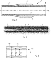
- connection tube 1 according to an embodiment of the present disclosure is shown in fig. 1 .
- the connection tube 1 has a central through-hole extending along a longitudinal axis A and has a first end portion 2 of a first alloy and a second end portion 3 of a second alloy. Between the end portions, a middle portion 4 which is double-layered extends. In the middle portion 4, the second alloy forms an annular inner layer 5 and the first alloy forms an annular outer layer 6. A metallic bond has been formed between the annular inner and outer layers 5, 6.
- the annular inner and outer layers 5, 6 are mechanically interlocked by means of at least one helically extending thread 7 formed in an interface between said layers 5, 6.
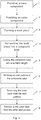
- the helically extending thread 7 is shown in fig. 2 , showing a cross sectional picture of a portion of a connection tube 1 according to an embodiment of the present disclosure.
- connection tube 1 has an inner diameter which is constant along the connection tube 1, i.e. at the first end portion 2, the middle portion 4 and the second end portion 3.
- the inner diameter may also vary along the connection tube, such that one of the end portions has a larger inner diameter than the other end portion.
- the connection tube 1 further has an outer diameter that is larger at the middle portion 4 than at the end portions 2, 3.
- a wall thickness of the connection tube 1 is therefore larger at the middle portion 4 than at the end portions 2, 3.
- the wall thickness at the middle portion 4 may be approximately double the wall thickness at the end portions 2, 3.
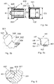
- a composite tube 101 as shown in fig. 3 is first manufactured, having an annular outer layer 102 and an annular inner layer 103 and extending along the longitudinal axis A.
- a method for manufacturing a connection tube 1 is schematically illustrated in fig. 4 .
- a base component 301 of the second alloy which is to form the inner layer 5 of the connection tube 1 shown in fig. 1 .
- the base component 301 is a tube of circular cross section, having a central through-hole extending along the longitudinal axis A.
- An externally threaded section 302 is provided, having a helical thread 306 (see fig. 5b ) formed in an outer peripheral surface of the base component 301.
- the threaded section may extend over the entire base component or over a portion of the base component. In the embodiment shown in figs. 5a-c , it extends over an end portion of the base component 301, constituting a major part of the base component.
- the shown base component 301 also has a relatively short non-threaded section 303 adjacent the threaded section 302.
- An inner diameter d of the base component is constant or essentially constant along the longitudinal axis, but an outer diameter D1 of the non-threaded section 303 is larger than an outer diameter D2 of the threaded section 302.
- an outer component 401 of the first alloy is provided.
- the outer component 401 is also a tube of circular cross section, having a central through-hole extending along the longitudinal axis A.
- the outer component 401 has a length in the longitudinal direction corresponding to a length of the threaded section 302 of the base component 301.
- the outer component 401 has an internally threaded section 402, in the shown embodiment extending along the entire length of the outer component 401.
- a helical thread 406 (see fig. 5c ) is formed in an inner peripheral surface of the outer component 401.
- the outer component 401 is thereby configured for threaded engagement with the externally threaded section 302 of the base component 301.
- An outer diameter D3 of the outer component 401 is equal to or essentially equal to the outer diameter D1 of the non-threaded section 303 of the base component 301, while an inner diameter d2 of the outer component 401 matches the outer diameter D2 of the threaded section 302 of the base component 301.
- a tubular work piece is formed by mounting the outer component 401 around the base component 301 such that the internally threaded section 402 of the outer component 401 is in engagement with the externally threaded section 302 of the base component 301, i.e. by threading the outer component 401 onto the threaded end portion of the base component 301.
- a mechanical interlock is thereby formed between the threaded sections 302, 402.
- a fourth step 4 the work piece formed in the third step 3 is hot worked, e.g. by means of hot extrusion. During hot working, a metallic bond is formed between the threaded sections 302, 402 while the mechanical interlock is maintained. An outer diameter of the work piece is also reduced and a composite tube is formed. The composite tube may be straightened and/or pickled after hot working.
- the composite tube is cut into a suitable length, for example by cutting off the ends of the composite tube so that possible defects and undesired features are removed.
- a middle part of the composite tube corresponding to the composite tube 101 shown in fig. 3 , may thereafter be used in the following steps.
- the composite tube 101 has a dimension defined by an outer diameter ⁇ 1, an inner diameter ⁇ 2 and an interfacial diameter ⁇ 3.
- a first end portion 104 of the composite tube 101 which first end portion 104 is to form the first end portion 2 of the connection tube 1, is worked such that the inner and outer diameters ⁇ 1, ⁇ 2 of the composite tube 101 gradually decreases from a middle portion 105 of the composite tube toward the first end portion 104 such as shown schematically in fig. 7 .
- This can be achieved for example by compressing the first end portion 104 or by expanding the second end portion 106.
- a seventh step 7 the annular inner layer 103 is removed from the first end portion 104 thereby an increased inner diameter ⁇ 2 is obtained, for example by cutting machining.
- the annular outer layer 102 is removed from a second end portion 106 of the composite tube 101, for example by cutting machining, thus forming a connection tube 1 having a first end portion 2 of the first alloy and a second end portion 3 of the second alloy such as shown in fig. 1 .
- One or both of the end portions may, if desired, be provided with an internal or external thread adapted for threaded engagement with a threaded end of a tube.
- the end portions may be configured to be joined with other tubes by means of welding.
- the components 301, 401 shown in fig. 5a are adapted for hot extrusion by pushing the work piece through an extrusion die with a leading end first, wherein the leading end is the end at which the outer component 401 is mounted.
- a transition surface 308 between the externally threaded section 302 of the base component 301 and the non-threaded section 303 is smooth, without sharp edges.
- the transition surface 308 is shown in more detail in fig. 5b , showing a magnification of the encircled area B from fig. 5a .
- the transition surface is in cross section shaped as an inverted S with a concave portion 304 closest to the threaded section 302, and a convex portion 305 closest to the non-threaded section 303.
- the outer component 401 has an end surface 408 with a corresponding S-shape with a convex portion 404 close to the internal thread 406, and a concave portion 405 close to an outer peripheral surface 407 of the outer component 401 as shown in fig.5c , showing a magnification of the encircled area C from fig, 5a .
- the concave portion 405 of the end surface 408 will thereby overlap with the convex portion 305 of the transition surface 308, which prevents separation and penetration of oxygen during the extrusion process.
- the base component 301 is formed with a C-shaped concave transition surface 308, such that it floats over a rounded annular end surface 408 of the outer component 401 during extrusion and forms a seal.
- An outer peripheral surface 307 of the base component 301 thus overlaps the outer peripheral surface 407 of the outer component 401 when the components 301, 401 are mounted to form the work piece.
- a method for connecting two tubes 8, 9 of different alloys according to an embodiment of the present disclosure in order to form a tubular product 10 as shown in fig. 8 comprises providing a connection tube 1 as described above.
- the first alloy of the connection tube 1 is selected so that it is compatible with an alloy of a first one of the two tubes 8, 9 that are to be connected, and the second alloy of the connection tube 1 is selected so that it is compatible with an alloy of a second one of the two tubes 8, 9.
- the first tube 8 and the first end portion 2 of the connection tube 1 are joined together, e.g. by welding or by threaded engagement, depending on e.g. the weldability of the alloys used and the requirements on the joint.
- the second tube 9 and the second end portion 3 of the connection tube 1 are thereafter joined together, using a technique suitable with regard to e.g. the weldability of the alloys used and the requirements on the joint.
- the formed tubular product 10 comprises the first tube 8, the second tube 9 and the connection tube 1.
- connection tubes 1 as shown in fig. 1-2 were manufactured.
- the first alloy was in this case an austenitic stainless steel alloy according to ASTM 304L.
- the composition of the first alloy as measured in percent by weight (wt.%) is disclosed in Table I.
- Table I C Si Mn P S Cr Ni Fe ⁇ 0.030 0.5 1.3 ⁇ 0.030 ⁇ 0.015 18.5 10 balance
- the second alloy was a carbon steel according to ASTM Grade A-1 having a composition in wt.% as disclosed in Table II.
- Table II C Si Mn P S Fe 0.2 0.3 0.7 ⁇ 0.035 ⁇ 0.035 Balance
- Each base component had a total length of 520 mm, an outer diameter of 140 mm, and an inner diameter of 50 mm.
- An externally threaded section having a length of 130 mm was formed by cutting machining.
- the outer components each had a length of 130 mm and an inner diameter of 110 mm and were provided with an internal thread.
- the components had the transitional design shown in fig. 5a-c .
- the outer components were washed in an alkaline ultrasonic bath and the base components were degreased using ethanol. The outer components were thereafter threaded onto the base components to form work pieces.
- the work pieces were pre-heated at 400°C for four hours and were thereafter hot extruded with the end on which the outer component was mounted as the leading end.
- the work pieces were subsequently cooled, straightened and pickled to form composite tubes.
- a double-layered middle part of each resulting composite tube was cut out and heated.
- a second end portion 106 was expanded (upset) as shown in fig. 7 . Thereafter, the annular inner layer 103 was removed from the first end portion 104 and the annular outer layer 102 was removed from the second end portion 106 using cutting machining, thereby forming connection tubes.
Landscapes
- Engineering & Computer Science (AREA)
- Mechanical Engineering (AREA)
- General Engineering & Computer Science (AREA)
- Non-Disconnectible Joints And Screw-Threaded Joints (AREA)
- Extrusion Of Metal (AREA)
- Pressure Welding/Diffusion-Bonding (AREA)
- Mutual Connection Of Rods And Tubes (AREA)
- Rigid Pipes And Flexible Pipes (AREA)
Claims (9)
- Verfahren zum Herstellen eines Verbindungsrohrs (1) zum Verbinden von zwei Rohren (8, 9) aus verschiedenen Legierungen, wobei das Verbindungsrohr (1) einen ersten Endabschnitt (2) und einen zweiten Endabschnitt (3) aufweist, das Verfahren folgende Schritte umfassend:- Bilden eines Verbundrohrs (101) mit einer ringförmigen Außenschicht (102) aus einer ersten Legierung und einer ringförmigen Innenschicht (103) aus einer zweiten Legierung,- Bearbeiten eines ersten Endabschnitts (104) des Verbundrohrs (101), derart, dass ein Durchmesser des Verbundrohrs (101) allmählich von einem mittleren Abschnitt (105) des Verbundrohrs zum ersten Endabschnitt (104) hin abnimmt,- Entfernen der ringförmigen Innenschicht (103) vom ersten Endabschnitt (104), derart, dass ein Innendurchmesser am ersten Endabschnitt (2) einem Innendurchmesser am zweiten Endabschnitt (3) entspricht, gekennzeichnet durch das- Entfernen der ringförmigen Außenschicht (102) von einem zweiten Endabschnitt (106) des Verbundrohrs (101) derart, dass ein mittlerer Abschnitt (4), der sich zwischen dem ersten Endabschnitt (2) und dem zweiten Endabschnitt (3) erstreckt, eine größere Wandstärke aufweist als jeder der Endabschnitte (2, 3), wodurch ein Verbindungsrohr (1) mit einem ersten Endabschnitt (2) aus der ersten Legierung und einem zweiten Endabschnitt (3) aus der zweiten Legierung gebildet wird, und dadurch, dass der Schritt des Bildens eines Verbundrohrs (101) die folgenden Schritte umfasst:- Bereitstellen einer ringförmigen Basiskomponente (301) aus der zweiten Legierung, wobei die ringförmige Basiskomponente (301) ein zentrales Durchgangsloch aufweist, das sich entlang einer Längsachse (A) der ringförmigen Basiskomponente (301) erstreckt, und wobei die ringförmige Basiskomponente (301) einen Außengewindeabschnitt (302) aufweist,- Bereitstellen einer ringförmigen Außenkomponente (401) aus der ersten Legierung, wobei die ringförmige Außenkomponente (401) einen Innengewindeabschnitt (402) aufweist, der konfiguriert ist, um in den Außengewindeabschnitt (302) der ringförmigen Basiskomponente (301) einzugreifen,- Bilden eines rohrförmigen Werkstücks durch Montieren der ringförmigen Außenkomponente (401) um die ringförmige Basiskomponente (301), derart, dass der Innengewindeabschnitt (402) der Außenkomponente (401) in Eingriff mit dem Außengewindeabschnitt (302) der ringförmigen Basiskomponente (301) steht, Bilden einer mechanischen Verriegelung zwischen den Gewindeabschnitten (302, 402),- Warmbearbeiten des Werkstücks, sodass einerseits eine metallische Bindung zwischen den Gewindeabschnitten (302, 402) der ringförmigen Außenkomponente (401) und der ringförmigen Basiskomponente (301) gebildet wird, während die mechanische Verriegelung beibehalten wird, und sodass andererseits das Werkstück gelängt wird und ein Außendurchmesser des rohrförmigen Werkstücks verringert wird, wodurch ein Verbundrohr (101) gebildet wird;
wobei der Warmbearbeitungsschritt Strangpressen umfasst. - Verfahren nach Anspruch 1, wobei das Verbundrohr (101) eine Abmessung aufweist, die durch einen Außendurchmesser (φ1), einen Innendurchmesser (φ2) und einen Grenzflächendurchmesser (φ3) definiert ist, und wobei der Schritt der Bearbeitung des ersten Endabschnitts (104) des Verbundrohrs (101) derart ausgeführt wird, dass der Grenzflächendurchmesser (φ3) des ersten Endabschnitts (104) dem Innendurchmesser (φ2) des mittleren Abschnitts (105) entspricht.
- Verfahren nach Anspruch 1 oder 2, wobei zumindest einer der Schritte des Entfernens der ringförmigen Innenschicht (103) und des Entfernens der ringförmigen Außenschicht (102) spanendes Bearbeiten und/oder abrasives Bearbeiten umfasst.
- Verfahren nach einem der Ansprüche 1-3, wobei sich der Außengewindeabschnitt entlang einer gesamten axialen Länge der ringförmigen Basiskomponente erstreckt.
- Verfahren nach einem der Ansprüche 1-3, wobei sich der Innengewindeabschnitt (402) entlang einer gesamten axialen Länge der ringförmigen Außenkomponente (401) erstreckt.
- Verfahren nach einem der Ansprüche 1-5, wobei die erste Legierung aus einer rostfreien Stahllegierung, einer Nickelbasislegierung, einer Eisen-Chrom-Aluminiumlegierung, einer Kohlenstoffstahllegierung, einer Zirkoniumlegierung, einer Aluminiumlegierung, einer Kupferlegierung oder einer Titanlegierung ausgewählt ist.
- Verfahren nach einem der Ansprüche 1-6, wobei die zweite Legierung eine andere Zusammensetzung aufweist als die erste Legierung und ausgewählt ist aus einer rostfreien Stahllegierung, einer Nickelbasislegierung, einer Eisen-Chrom-Aluminiumlegierung, einer Kohlenstoffstahllegierung, einer Zirkoniumlegierung, einer Aluminiumlegierung, einer Kupferlegierung oder einer Titanlegierung.
- Verbindungsrohr (1) zum Verbinden von zwei Rohren (8, 9) aus verschiedenen Legierungen, die gemäß den Ansprüchen 1-7 hergestellt sind, wobei das Verbindungsrohr (1) ein zentrales Durchgangsloch aufweist, das sich entlang einer Längsachse (A) erstreckt und Folgendes umfasst:- einen ersten Endabschnitt (2) aus einer ersten Legierung,- einen zweiten Endabschnitt (3) aus einer zweiten Legierung,- einen mittleren Abschnitt (4), der sich zwischen dem ersten Endabschnitt (2) und dem zweiten Endabschnitt (3) erstreckt, wobei der mittlere Abschnitt (4) zumindest teilweise doppellagig ist, wobei die zweite Legierung eine ringförmige Innenschicht (5) bildet und die erste Legierung eine ringförmige Außenschicht (6) bildet, wobei eine metallische Bindung zwischen den Schichten (5, 6) gebildet wurde,wobei
die ringförmige Innenschicht (5) und die ringförmige Außenschicht (6) beide mechanisch durch zumindest ein sich wendelförmig erstreckendes Gewinde (7), das in einer Grenzfläche zwischen den Schichten (5, 6) gebildet wird, verriegelt sind und die Grenzfläche, die ein sich erstreckendes Gewinde aufweist, auch eine metallische Bindung aufweist, die zwischen den Gewindeabschnitten gebildet wird, und
wobei ein Innendurchmesser am ersten Endabschnitt (2) einem Innendurchmesser am zweiten Endabschnitt (3) entspricht;
und wobei der mittlere Abschnitt (4) eine größere Wandstärke aufweist als jeder der Endabschnitte (2, 3). - Verbindungsrohr nach Anspruch 8, wobei zumindest einer der Endabschnitte mit einem Innen- oder Außengewinde versehen ist, das für den Gewindeeingriff mit einem Gewindezapfen eines Rohrs ausgebildet ist.
Applications Claiming Priority (2)
| Application Number | Priority Date | Filing Date | Title |
|---|---|---|---|
| EP16206891 | 2016-12-23 | ||
| PCT/EP2017/084513 WO2018115501A1 (en) | 2016-12-23 | 2017-12-22 | A connection tube and its method of manufacturing |
Publications (2)
| Publication Number | Publication Date |
|---|---|
| EP3558554A1 EP3558554A1 (de) | 2019-10-30 |
| EP3558554B1 true EP3558554B1 (de) | 2021-02-17 |
Family
ID=57909421
Family Applications (1)
| Application Number | Title | Priority Date | Filing Date |
|---|---|---|---|
| EP17823160.1A Not-in-force EP3558554B1 (de) | 2016-12-23 | 2017-12-22 | Verbindungsrohr und verfahren zu dessen herstellung |
Country Status (7)
| Country | Link |
|---|---|
| US (1) | US11679428B2 (de) |
| EP (1) | EP3558554B1 (de) |
| JP (1) | JP6942186B2 (de) |
| KR (1) | KR102386168B1 (de) |
| CN (1) | CN110099757B (de) |
| ES (1) | ES2857579T3 (de) |
| WO (1) | WO2018115501A1 (de) |
Families Citing this family (5)
| Publication number | Priority date | Publication date | Assignee | Title |
|---|---|---|---|---|
| EP3797239A1 (de) * | 2018-05-22 | 2021-03-31 | AB Sandvik Materials Technology | Rohrförmiges element und anordnungen |
| CN111810058A (zh) * | 2020-07-06 | 2020-10-23 | 中国石油天然气集团有限公司 | 一种煤炭地下气化连续管及其连接方法 |
| CN112742891B (zh) * | 2020-12-16 | 2022-12-13 | 湖南华翔医疗科技有限公司 | 一种医用可降解锌基复合管材的制备方法 |
| CN116407738B (zh) * | 2021-12-31 | 2026-02-17 | 上海博畅医疗科技有限公司 | 一种多段管的加工方法和球囊导管 |
| CN115813494B (zh) * | 2022-12-05 | 2026-02-27 | 深圳臣诺医疗器械有限公司 | 超声波手术刀杆及手术器械 |
Family Cites Families (13)
| Publication number | Priority date | Publication date | Assignee | Title |
|---|---|---|---|---|
| BE511483A (de) * | ||||
| DE906167C (de) * | 1951-10-09 | 1954-03-11 | Westdeutsche Mannesmannroehren | Schweissverbindung fuer metallische Werkstuecke, insbesondere Stahlrohre |
| AT184039B (de) * | 1952-09-23 | 1955-12-10 | Schoeller Bleckmann Stahlwerke | Verfahren zur Herstellung von Rohrverbindungen an Bohrgestängen für Tiefbohrungen |
| US3140108A (en) * | 1960-07-28 | 1964-07-07 | Joseph Lester Klein | Process and product of metallurgically joining zirconium to ferrous metal |
| US3208776A (en) * | 1960-09-06 | 1965-09-28 | Hydrocarbon Research Inc | Transition couplings |
| SE338294B (de) * | 1968-01-03 | 1971-09-06 | Cnen | |
| JPS5540311A (en) * | 1978-09-08 | 1980-03-21 | Tokyo Shibaura Electric Co | Jointing construction of pipes having differencial material quality |
| JPS6199590A (ja) * | 1984-10-22 | 1986-05-17 | Kuroki Kogyosho:Kk | 異種金属パイプ同志のパイプジョイントの製造方法 |
| US20060071473A1 (en) * | 2004-10-05 | 2006-04-06 | Sivley Robert S Iv | Helical groove for a tubular connection |
| DE202007009801U1 (de) * | 2007-07-13 | 2008-11-20 | Witzenmann Gmbh | Anordnung zum fluiddichten Verbinden von zwei Rohrenden aus unterschiedlichen Metallen |
| JP2013044423A (ja) * | 2011-08-26 | 2013-03-04 | Taku Seisakusho:Kk | 配管 |
| CN104132207A (zh) * | 2014-08-09 | 2014-11-05 | 河北宏广橡塑金属制品有限公司 | 一种复合管接头及其制备方法 |
| CN205424245U (zh) * | 2016-01-13 | 2016-08-03 | 中国石油化工股份有限公司 | 接头连接装置 |
-
2017
- 2017-12-22 JP JP2019532697A patent/JP6942186B2/ja not_active Expired - Fee Related
- 2017-12-22 ES ES17823160T patent/ES2857579T3/es active Active
- 2017-12-22 EP EP17823160.1A patent/EP3558554B1/de not_active Not-in-force
- 2017-12-22 KR KR1020197020352A patent/KR102386168B1/ko not_active Expired - Fee Related
- 2017-12-22 US US16/472,238 patent/US11679428B2/en active Active
- 2017-12-22 WO PCT/EP2017/084513 patent/WO2018115501A1/en not_active Ceased
- 2017-12-22 CN CN201780079575.9A patent/CN110099757B/zh not_active Expired - Fee Related
Non-Patent Citations (1)
| Title |
|---|
| None * |
Also Published As
| Publication number | Publication date |
|---|---|
| KR20190100935A (ko) | 2019-08-29 |
| ES2857579T3 (es) | 2021-09-29 |
| WO2018115501A1 (en) | 2018-06-28 |
| CN110099757B (zh) | 2021-07-16 |
| JP2020509299A (ja) | 2020-03-26 |
| EP3558554A1 (de) | 2019-10-30 |
| JP6942186B2 (ja) | 2021-09-29 |
| US20190314877A1 (en) | 2019-10-17 |
| US11679428B2 (en) | 2023-06-20 |
| KR102386168B1 (ko) | 2022-04-12 |
| CN110099757A (zh) | 2019-08-06 |
Similar Documents
| Publication | Publication Date | Title |
|---|---|---|
| EP3558554B1 (de) | Verbindungsrohr und verfahren zu dessen herstellung | |
| EP3558555B1 (de) | Verfahren zur herstellung eines verbundstoffrohrs | |
| US7658419B2 (en) | Fitting and method for manufacturing a fitting | |
| JP6561394B2 (ja) | 拡張により多層パイプを製造するための方法および該方法によって製造される多層パイプ | |
| US6007923A (en) | Titanium alloy, member made of the titanium alloy and method for producing the titanium alloy member | |
| WO2012002866A1 (en) | A hollow gear ring and method for its manufacturing | |
| US20190022801A1 (en) | Method of making a corrosion resistant tube | |
| US5004143A (en) | Method of manufacturing clad bar | |
| US20080164695A1 (en) | Ferrules Manufactured From Hollow Stock | |
| US4515000A (en) | Method for manufacturing consumable welding spacer | |
| JPH04315524A (ja) | 銅材とアルミニウム材との接合用部材及びその製造方法 | |
| KR20170132808A (ko) | 내식성 및 가공성이 뛰어난 알루미늄 합금관 및 그 제조 방법 | |
| RU2403117C2 (ru) | Способ изготовления биметаллических переходников малого диаметра многопереходной штамповкой | |
| JP2006193765A (ja) | アルミニウム合金製部材の製造方法 | |
| JP4975354B2 (ja) | 高強度溶接鋼管の製造方法 | |
| RU2402397C1 (ru) | Способ изготовления биметаллических переходников | |
| JPS5939444A (ja) | 鋼製フランジの製造法 | |
| JP2002219512A (ja) | 金属溶接管用素材および金属溶接管用素材の製造方法ならびに金属溶接管の製造方法 | |
| SU1278160A1 (ru) | Многослойный пруток | |
| JPH0338928B2 (de) | ||
| EP1379341A1 (de) | Verfahren und vorrichtung zur herstellung eines geschlossenen profils und gemäss dem verfahren hergestelltes profil | |
| JPS60106617A (ja) | 外面クラツド押出加工用ビレツト及びその製造方法 | |
| JPH03275218A (ja) | 二重管レデューサ管継手の製造方法 | |
| JPH08155535A (ja) | 熱間押出し製管用ダイス |
Legal Events
| Date | Code | Title | Description |
|---|---|---|---|
| STAA | Information on the status of an ep patent application or granted ep patent |
Free format text: STATUS: UNKNOWN |
|
| STAA | Information on the status of an ep patent application or granted ep patent |
Free format text: STATUS: THE INTERNATIONAL PUBLICATION HAS BEEN MADE |
|
| PUAI | Public reference made under article 153(3) epc to a published international application that has entered the european phase |
Free format text: ORIGINAL CODE: 0009012 |
|
| STAA | Information on the status of an ep patent application or granted ep patent |
Free format text: STATUS: REQUEST FOR EXAMINATION WAS MADE |
|
| 17P | Request for examination filed |
Effective date: 20190723 |
|
| AK | Designated contracting states |
Kind code of ref document: A1 Designated state(s): AL AT BE BG CH CY CZ DE DK EE ES FI FR GB GR HR HU IE IS IT LI LT LU LV MC MK MT NL NO PL PT RO RS SE SI SK SM TR |
|
| AX | Request for extension of the european patent |
Extension state: BA ME |
|
| DAV | Request for validation of the european patent (deleted) | ||
| DAX | Request for extension of the european patent (deleted) | ||
| GRAP | Despatch of communication of intention to grant a patent |
Free format text: ORIGINAL CODE: EPIDOSNIGR1 |
|
| STAA | Information on the status of an ep patent application or granted ep patent |
Free format text: STATUS: GRANT OF PATENT IS INTENDED |
|
| INTG | Intention to grant announced |
Effective date: 20201103 |
|
| GRAS | Grant fee paid |
Free format text: ORIGINAL CODE: EPIDOSNIGR3 |
|
| GRAA | (expected) grant |
Free format text: ORIGINAL CODE: 0009210 |
|
| STAA | Information on the status of an ep patent application or granted ep patent |
Free format text: STATUS: THE PATENT HAS BEEN GRANTED |
|
| AK | Designated contracting states |
Kind code of ref document: B1 Designated state(s): AL AT BE BG CH CY CZ DE DK EE ES FI FR GB GR HR HU IE IS IT LI LT LU LV MC MK MT NL NO PL PT RO RS SE SI SK SM TR |
|
| REG | Reference to a national code |
Ref country code: GB Ref legal event code: FG4D |
|
| REG | Reference to a national code |
Ref country code: CH Ref legal event code: EP |
|
| REG | Reference to a national code |
Ref country code: DE Ref legal event code: R096 Ref document number: 602017032912 Country of ref document: DE |
|
| REG | Reference to a national code |
Ref country code: AT Ref legal event code: REF Ref document number: 1360803 Country of ref document: AT Kind code of ref document: T Effective date: 20210315 |
|
| REG | Reference to a national code |
Ref country code: IE Ref legal event code: FG4D |
|
| REG | Reference to a national code |
Ref country code: SE Ref legal event code: TRGR |
|
| REG | Reference to a national code |
Ref country code: LT Ref legal event code: MG9D |
|
| REG | Reference to a national code |
Ref country code: NL Ref legal event code: MP Effective date: 20210217 |
|
| PG25 | Lapsed in a contracting state [announced via postgrant information from national office to epo] |
Ref country code: LT Free format text: LAPSE BECAUSE OF FAILURE TO SUBMIT A TRANSLATION OF THE DESCRIPTION OR TO PAY THE FEE WITHIN THE PRESCRIBED TIME-LIMIT Effective date: 20210217 Ref country code: BG Free format text: LAPSE BECAUSE OF FAILURE TO SUBMIT A TRANSLATION OF THE DESCRIPTION OR TO PAY THE FEE WITHIN THE PRESCRIBED TIME-LIMIT Effective date: 20210517 Ref country code: PT Free format text: LAPSE BECAUSE OF FAILURE TO SUBMIT A TRANSLATION OF THE DESCRIPTION OR TO PAY THE FEE WITHIN THE PRESCRIBED TIME-LIMIT Effective date: 20210617 Ref country code: NO Free format text: LAPSE BECAUSE OF FAILURE TO SUBMIT A TRANSLATION OF THE DESCRIPTION OR TO PAY THE FEE WITHIN THE PRESCRIBED TIME-LIMIT Effective date: 20210517 Ref country code: GR Free format text: LAPSE BECAUSE OF FAILURE TO SUBMIT A TRANSLATION OF THE DESCRIPTION OR TO PAY THE FEE WITHIN THE PRESCRIBED TIME-LIMIT Effective date: 20210518 Ref country code: FI Free format text: LAPSE BECAUSE OF FAILURE TO SUBMIT A TRANSLATION OF THE DESCRIPTION OR TO PAY THE FEE WITHIN THE PRESCRIBED TIME-LIMIT Effective date: 20210217 Ref country code: HR Free format text: LAPSE BECAUSE OF FAILURE TO SUBMIT A TRANSLATION OF THE DESCRIPTION OR TO PAY THE FEE WITHIN THE PRESCRIBED TIME-LIMIT Effective date: 20210217 |
|
| REG | Reference to a national code |
Ref country code: AT Ref legal event code: MK05 Ref document number: 1360803 Country of ref document: AT Kind code of ref document: T Effective date: 20210217 |
|
| PG25 | Lapsed in a contracting state [announced via postgrant information from national office to epo] |
Ref country code: LV Free format text: LAPSE BECAUSE OF FAILURE TO SUBMIT A TRANSLATION OF THE DESCRIPTION OR TO PAY THE FEE WITHIN THE PRESCRIBED TIME-LIMIT Effective date: 20210217 Ref country code: PL Free format text: LAPSE BECAUSE OF FAILURE TO SUBMIT A TRANSLATION OF THE DESCRIPTION OR TO PAY THE FEE WITHIN THE PRESCRIBED TIME-LIMIT Effective date: 20210217 Ref country code: NL Free format text: LAPSE BECAUSE OF FAILURE TO SUBMIT A TRANSLATION OF THE DESCRIPTION OR TO PAY THE FEE WITHIN THE PRESCRIBED TIME-LIMIT Effective date: 20210217 Ref country code: RS Free format text: LAPSE BECAUSE OF FAILURE TO SUBMIT A TRANSLATION OF THE DESCRIPTION OR TO PAY THE FEE WITHIN THE PRESCRIBED TIME-LIMIT Effective date: 20210217 |
|
| REG | Reference to a national code |
Ref country code: ES Ref legal event code: FG2A Ref document number: 2857579 Country of ref document: ES Kind code of ref document: T3 Effective date: 20210929 |
|
| PG25 | Lapsed in a contracting state [announced via postgrant information from national office to epo] |
Ref country code: IS Free format text: LAPSE BECAUSE OF FAILURE TO SUBMIT A TRANSLATION OF THE DESCRIPTION OR TO PAY THE FEE WITHIN THE PRESCRIBED TIME-LIMIT Effective date: 20210617 |
|
| PG25 | Lapsed in a contracting state [announced via postgrant information from national office to epo] |
Ref country code: AT Free format text: LAPSE BECAUSE OF FAILURE TO SUBMIT A TRANSLATION OF THE DESCRIPTION OR TO PAY THE FEE WITHIN THE PRESCRIBED TIME-LIMIT Effective date: 20210217 Ref country code: SM Free format text: LAPSE BECAUSE OF FAILURE TO SUBMIT A TRANSLATION OF THE DESCRIPTION OR TO PAY THE FEE WITHIN THE PRESCRIBED TIME-LIMIT Effective date: 20210217 Ref country code: EE Free format text: LAPSE BECAUSE OF FAILURE TO SUBMIT A TRANSLATION OF THE DESCRIPTION OR TO PAY THE FEE WITHIN THE PRESCRIBED TIME-LIMIT Effective date: 20210217 |
|
| REG | Reference to a national code |
Ref country code: DE Ref legal event code: R097 Ref document number: 602017032912 Country of ref document: DE |
|
| PG25 | Lapsed in a contracting state [announced via postgrant information from national office to epo] |
Ref country code: RO Free format text: LAPSE BECAUSE OF FAILURE TO SUBMIT A TRANSLATION OF THE DESCRIPTION OR TO PAY THE FEE WITHIN THE PRESCRIBED TIME-LIMIT Effective date: 20210217 Ref country code: DK Free format text: LAPSE BECAUSE OF FAILURE TO SUBMIT A TRANSLATION OF THE DESCRIPTION OR TO PAY THE FEE WITHIN THE PRESCRIBED TIME-LIMIT Effective date: 20210217 Ref country code: SK Free format text: LAPSE BECAUSE OF FAILURE TO SUBMIT A TRANSLATION OF THE DESCRIPTION OR TO PAY THE FEE WITHIN THE PRESCRIBED TIME-LIMIT Effective date: 20210217 |
|
| PLBE | No opposition filed within time limit |
Free format text: ORIGINAL CODE: 0009261 |
|
| STAA | Information on the status of an ep patent application or granted ep patent |
Free format text: STATUS: NO OPPOSITION FILED WITHIN TIME LIMIT |
|
| 26N | No opposition filed |
Effective date: 20211118 |
|
| PG25 | Lapsed in a contracting state [announced via postgrant information from national office to epo] |
Ref country code: AL Free format text: LAPSE BECAUSE OF FAILURE TO SUBMIT A TRANSLATION OF THE DESCRIPTION OR TO PAY THE FEE WITHIN THE PRESCRIBED TIME-LIMIT Effective date: 20210217 |
|
| PG25 | Lapsed in a contracting state [announced via postgrant information from national office to epo] |
Ref country code: SI Free format text: LAPSE BECAUSE OF FAILURE TO SUBMIT A TRANSLATION OF THE DESCRIPTION OR TO PAY THE FEE WITHIN THE PRESCRIBED TIME-LIMIT Effective date: 20210217 |
|
| PG25 | Lapsed in a contracting state [announced via postgrant information from national office to epo] |
Ref country code: IS Free format text: LAPSE BECAUSE OF FAILURE TO SUBMIT A TRANSLATION OF THE DESCRIPTION OR TO PAY THE FEE WITHIN THE PRESCRIBED TIME-LIMIT Effective date: 20210617 |
|
| PG25 | Lapsed in a contracting state [announced via postgrant information from national office to epo] |
Ref country code: MC Free format text: LAPSE BECAUSE OF FAILURE TO SUBMIT A TRANSLATION OF THE DESCRIPTION OR TO PAY THE FEE WITHIN THE PRESCRIBED TIME-LIMIT Effective date: 20210217 |
|
| REG | Reference to a national code |
Ref country code: CH Ref legal event code: PL |
|
| REG | Reference to a national code |
Ref country code: BE Ref legal event code: MM Effective date: 20211231 |
|
| PG25 | Lapsed in a contracting state [announced via postgrant information from national office to epo] |
Ref country code: LU Free format text: LAPSE BECAUSE OF NON-PAYMENT OF DUE FEES Effective date: 20211222 Ref country code: IE Free format text: LAPSE BECAUSE OF NON-PAYMENT OF DUE FEES Effective date: 20211222 |
|
| PG25 | Lapsed in a contracting state [announced via postgrant information from national office to epo] |
Ref country code: BE Free format text: LAPSE BECAUSE OF NON-PAYMENT OF DUE FEES Effective date: 20211231 |
|
| PG25 | Lapsed in a contracting state [announced via postgrant information from national office to epo] |
Ref country code: LI Free format text: LAPSE BECAUSE OF NON-PAYMENT OF DUE FEES Effective date: 20211231 Ref country code: CH Free format text: LAPSE BECAUSE OF NON-PAYMENT OF DUE FEES Effective date: 20211231 |
|
| PG25 | Lapsed in a contracting state [announced via postgrant information from national office to epo] |
Ref country code: CY Free format text: LAPSE BECAUSE OF FAILURE TO SUBMIT A TRANSLATION OF THE DESCRIPTION OR TO PAY THE FEE WITHIN THE PRESCRIBED TIME-LIMIT Effective date: 20210217 |
|
| P01 | Opt-out of the competence of the unified patent court (upc) registered |
Effective date: 20230526 |
|
| PG25 | Lapsed in a contracting state [announced via postgrant information from national office to epo] |
Ref country code: HU Free format text: LAPSE BECAUSE OF FAILURE TO SUBMIT A TRANSLATION OF THE DESCRIPTION OR TO PAY THE FEE WITHIN THE PRESCRIBED TIME-LIMIT; INVALID AB INITIO Effective date: 20171222 |
|
| REG | Reference to a national code |
Ref country code: GB Ref legal event code: 732E Free format text: REGISTERED BETWEEN 20231026 AND 20231101 |
|
| PGFP | Annual fee paid to national office [announced via postgrant information from national office to epo] |
Ref country code: GB Payment date: 20231102 Year of fee payment: 7 |
|
| PGFP | Annual fee paid to national office [announced via postgrant information from national office to epo] |
Ref country code: SE Payment date: 20231110 Year of fee payment: 7 Ref country code: IT Payment date: 20231110 Year of fee payment: 7 Ref country code: DE Payment date: 20231031 Year of fee payment: 7 Ref country code: CZ Payment date: 20231128 Year of fee payment: 7 Ref country code: FR Payment date: 20231122 Year of fee payment: 7 |
|
| REG | Reference to a national code |
Ref country code: DE Ref legal event code: R081 Ref document number: 602017032912 Country of ref document: DE Owner name: ALLEIMA TUBE AB, SE Free format text: FORMER OWNER: SANDVIK INTELLECTUAL PROPERTY AB, SANDVIKEN, SE |
|
| PGFP | Annual fee paid to national office [announced via postgrant information from national office to epo] |
Ref country code: ES Payment date: 20240111 Year of fee payment: 7 |
|
| PG25 | Lapsed in a contracting state [announced via postgrant information from national office to epo] |
Ref country code: MK Free format text: LAPSE BECAUSE OF FAILURE TO SUBMIT A TRANSLATION OF THE DESCRIPTION OR TO PAY THE FEE WITHIN THE PRESCRIBED TIME-LIMIT Effective date: 20210217 |
|
| PG25 | Lapsed in a contracting state [announced via postgrant information from national office to epo] |
Ref country code: MT Free format text: LAPSE BECAUSE OF FAILURE TO SUBMIT A TRANSLATION OF THE DESCRIPTION OR TO PAY THE FEE WITHIN THE PRESCRIBED TIME-LIMIT Effective date: 20210217 |
|
| REG | Reference to a national code |
Ref country code: ES Ref legal event code: PC2A Owner name: ALLEIMA TUBE AB Effective date: 20240927 |
|
| REG | Reference to a national code |
Ref country code: DE Ref legal event code: R119 Ref document number: 602017032912 Country of ref document: DE |
|
| PG25 | Lapsed in a contracting state [announced via postgrant information from national office to epo] |
Ref country code: CZ Free format text: LAPSE BECAUSE OF NON-PAYMENT OF DUE FEES Effective date: 20241222 |
|
| REG | Reference to a national code |
Ref country code: SE Ref legal event code: EUG |
|
| GBPC | Gb: european patent ceased through non-payment of renewal fee |
Effective date: 20241222 |
|
| PG25 | Lapsed in a contracting state [announced via postgrant information from national office to epo] |
Ref country code: DE Free format text: LAPSE BECAUSE OF NON-PAYMENT OF DUE FEES Effective date: 20250701 |
|
| PG25 | Lapsed in a contracting state [announced via postgrant information from national office to epo] |
Ref country code: IT Free format text: LAPSE BECAUSE OF NON-PAYMENT OF DUE FEES Effective date: 20241222 |
|
| PG25 | Lapsed in a contracting state [announced via postgrant information from national office to epo] |
Ref country code: GB Free format text: LAPSE BECAUSE OF NON-PAYMENT OF DUE FEES Effective date: 20241222 |
|
| PG25 | Lapsed in a contracting state [announced via postgrant information from national office to epo] |
Ref country code: FR Free format text: LAPSE BECAUSE OF NON-PAYMENT OF DUE FEES Effective date: 20241231 |
|
| PG25 | Lapsed in a contracting state [announced via postgrant information from national office to epo] |
Ref country code: TR Free format text: LAPSE BECAUSE OF FAILURE TO SUBMIT A TRANSLATION OF THE DESCRIPTION OR TO PAY THE FEE WITHIN THE PRESCRIBED TIME-LIMIT Effective date: 20210217 |
|
| REG | Reference to a national code |
Ref country code: ES Ref legal event code: FD2A Effective date: 20260204 |
|
| PG25 | Lapsed in a contracting state [announced via postgrant information from national office to epo] |
Ref country code: ES Free format text: LAPSE BECAUSE OF NON-PAYMENT OF DUE FEES Effective date: 20241223 |