EP3558520B1 - Verfahren zur vorreformierung eines kohlenwasserstoffhaltigen kraftstoffes in gegenwart eines strukturierten katalysators - Google Patents
Verfahren zur vorreformierung eines kohlenwasserstoffhaltigen kraftstoffes in gegenwart eines strukturierten katalysators Download PDFInfo
- Publication number
- EP3558520B1 EP3558520B1 EP18706586.7A EP18706586A EP3558520B1 EP 3558520 B1 EP3558520 B1 EP 3558520B1 EP 18706586 A EP18706586 A EP 18706586A EP 3558520 B1 EP3558520 B1 EP 3558520B1
- Authority
- EP
- European Patent Office
- Prior art keywords
- coating
- structured
- structured catalyst
- catalyst
- reforming
- Prior art date
- Legal status (The legal status is an assumption and is not a legal conclusion. Google has not performed a legal analysis and makes no representation as to the accuracy of the status listed.)
- Active
Links
Images





Classifications
-
- B—PERFORMING OPERATIONS; TRANSPORTING
- B01—PHYSICAL OR CHEMICAL PROCESSES OR APPARATUS IN GENERAL
- B01J—CHEMICAL OR PHYSICAL PROCESSES, e.g. CATALYSIS OR COLLOID CHEMISTRY; THEIR RELEVANT APPARATUS
- B01J23/00—Catalysts comprising metals or metal oxides or hydroxides, not provided for in group B01J21/00
- B01J23/10—Catalysts comprising metals or metal oxides or hydroxides, not provided for in group B01J21/00 of rare earths
-
- B—PERFORMING OPERATIONS; TRANSPORTING
- B01—PHYSICAL OR CHEMICAL PROCESSES OR APPARATUS IN GENERAL
- B01J—CHEMICAL OR PHYSICAL PROCESSES, e.g. CATALYSIS OR COLLOID CHEMISTRY; THEIR RELEVANT APPARATUS
- B01J37/00—Processes, in general, for preparing catalysts; Processes, in general, for activation of catalysts
- B01J37/02—Impregnation, coating or precipitation
- B01J37/0215—Coating
- B01J37/0217—Pretreatment of the substrate before coating
-
- B—PERFORMING OPERATIONS; TRANSPORTING
- B01—PHYSICAL OR CHEMICAL PROCESSES OR APPARATUS IN GENERAL
- B01J—CHEMICAL OR PHYSICAL PROCESSES, e.g. CATALYSIS OR COLLOID CHEMISTRY; THEIR RELEVANT APPARATUS
- B01J23/00—Catalysts comprising metals or metal oxides or hydroxides, not provided for in group B01J21/00
- B01J23/002—Mixed oxides other than spinels, e.g. perovskite
-
- B—PERFORMING OPERATIONS; TRANSPORTING
- B01—PHYSICAL OR CHEMICAL PROCESSES OR APPARATUS IN GENERAL
- B01J—CHEMICAL OR PHYSICAL PROCESSES, e.g. CATALYSIS OR COLLOID CHEMISTRY; THEIR RELEVANT APPARATUS
- B01J23/00—Catalysts comprising metals or metal oxides or hydroxides, not provided for in group B01J21/00
-
- B—PERFORMING OPERATIONS; TRANSPORTING
- B01—PHYSICAL OR CHEMICAL PROCESSES OR APPARATUS IN GENERAL
- B01J—CHEMICAL OR PHYSICAL PROCESSES, e.g. CATALYSIS OR COLLOID CHEMISTRY; THEIR RELEVANT APPARATUS
- B01J23/00—Catalysts comprising metals or metal oxides or hydroxides, not provided for in group B01J21/00
- B01J23/70—Catalysts comprising metals or metal oxides or hydroxides, not provided for in group B01J21/00 of the iron group metals or copper
- B01J23/76—Catalysts comprising metals or metal oxides or hydroxides, not provided for in group B01J21/00 of the iron group metals or copper combined with metals, oxides or hydroxides provided for in groups B01J23/02 - B01J23/36
- B01J23/83—Catalysts comprising metals or metal oxides or hydroxides, not provided for in group B01J21/00 of the iron group metals or copper combined with metals, oxides or hydroxides provided for in groups B01J23/02 - B01J23/36 with rare earths or actinides
-
- B—PERFORMING OPERATIONS; TRANSPORTING
- B01—PHYSICAL OR CHEMICAL PROCESSES OR APPARATUS IN GENERAL
- B01J—CHEMICAL OR PHYSICAL PROCESSES, e.g. CATALYSIS OR COLLOID CHEMISTRY; THEIR RELEVANT APPARATUS
- B01J23/00—Catalysts comprising metals or metal oxides or hydroxides, not provided for in group B01J21/00
- B01J23/70—Catalysts comprising metals or metal oxides or hydroxides, not provided for in group B01J21/00 of the iron group metals or copper
- B01J23/89—Catalysts comprising metals or metal oxides or hydroxides, not provided for in group B01J21/00 of the iron group metals or copper combined with noble metals
- B01J23/8933—Catalysts comprising metals or metal oxides or hydroxides, not provided for in group B01J21/00 of the iron group metals or copper combined with noble metals also combined with metals, or metal oxides or hydroxides provided for in groups B01J23/02 - B01J23/36
- B01J23/894—Catalysts comprising metals or metal oxides or hydroxides, not provided for in group B01J21/00 of the iron group metals or copper combined with noble metals also combined with metals, or metal oxides or hydroxides provided for in groups B01J23/02 - B01J23/36 with rare earths or actinides
-
- B—PERFORMING OPERATIONS; TRANSPORTING
- B01—PHYSICAL OR CHEMICAL PROCESSES OR APPARATUS IN GENERAL
- B01J—CHEMICAL OR PHYSICAL PROCESSES, e.g. CATALYSIS OR COLLOID CHEMISTRY; THEIR RELEVANT APPARATUS
- B01J35/00—Catalysts, in general, characterised by their form or physical properties
- B01J35/50—Catalysts, in general, characterised by their form or physical properties characterised by their shape or configuration
- B01J35/56—Foraminous structures having flow-through passages or channels, e.g. grids or three-dimensional [3D] monoliths
-
- B—PERFORMING OPERATIONS; TRANSPORTING
- B01—PHYSICAL OR CHEMICAL PROCESSES OR APPARATUS IN GENERAL
- B01J—CHEMICAL OR PHYSICAL PROCESSES, e.g. CATALYSIS OR COLLOID CHEMISTRY; THEIR RELEVANT APPARATUS
- B01J37/00—Processes, in general, for preparing catalysts; Processes, in general, for activation of catalysts
- B01J37/0009—Use of binding agents; Moulding; Pressing; Powdering; Granulating; Addition of materials ameliorating the mechanical properties of the product catalyst
- B01J37/0018—Addition of a binding agent or of material, later completely removed among others as result of heat treatment, leaching or washing,(e.g. forming of pores; protective layer, desintegrating by heat)
-
- B—PERFORMING OPERATIONS; TRANSPORTING
- B01—PHYSICAL OR CHEMICAL PROCESSES OR APPARATUS IN GENERAL
- B01J—CHEMICAL OR PHYSICAL PROCESSES, e.g. CATALYSIS OR COLLOID CHEMISTRY; THEIR RELEVANT APPARATUS
- B01J37/00—Processes, in general, for preparing catalysts; Processes, in general, for activation of catalysts
- B01J37/0009—Use of binding agents; Moulding; Pressing; Powdering; Granulating; Addition of materials ameliorating the mechanical properties of the product catalyst
- B01J37/0027—Powdering
- B01J37/0036—Grinding
-
- B—PERFORMING OPERATIONS; TRANSPORTING
- B01—PHYSICAL OR CHEMICAL PROCESSES OR APPARATUS IN GENERAL
- B01J—CHEMICAL OR PHYSICAL PROCESSES, e.g. CATALYSIS OR COLLOID CHEMISTRY; THEIR RELEVANT APPARATUS
- B01J37/00—Processes, in general, for preparing catalysts; Processes, in general, for activation of catalysts
- B01J37/02—Impregnation, coating or precipitation
- B01J37/0215—Coating
- B01J37/0219—Coating the coating containing organic compounds
-
- B—PERFORMING OPERATIONS; TRANSPORTING
- B01—PHYSICAL OR CHEMICAL PROCESSES OR APPARATUS IN GENERAL
- B01J—CHEMICAL OR PHYSICAL PROCESSES, e.g. CATALYSIS OR COLLOID CHEMISTRY; THEIR RELEVANT APPARATUS
- B01J37/00—Processes, in general, for preparing catalysts; Processes, in general, for activation of catalysts
- B01J37/02—Impregnation, coating or precipitation
- B01J37/0236—Drying, e.g. preparing a suspension, adding a soluble salt and drying
-
- B—PERFORMING OPERATIONS; TRANSPORTING
- B01—PHYSICAL OR CHEMICAL PROCESSES OR APPARATUS IN GENERAL
- B01J—CHEMICAL OR PHYSICAL PROCESSES, e.g. CATALYSIS OR COLLOID CHEMISTRY; THEIR RELEVANT APPARATUS
- B01J37/00—Processes, in general, for preparing catalysts; Processes, in general, for activation of catalysts
- B01J37/02—Impregnation, coating or precipitation
- B01J37/024—Multiple impregnation or coating
-
- B—PERFORMING OPERATIONS; TRANSPORTING
- B01—PHYSICAL OR CHEMICAL PROCESSES OR APPARATUS IN GENERAL
- B01J—CHEMICAL OR PHYSICAL PROCESSES, e.g. CATALYSIS OR COLLOID CHEMISTRY; THEIR RELEVANT APPARATUS
- B01J37/00—Processes, in general, for preparing catalysts; Processes, in general, for activation of catalysts
- B01J37/02—Impregnation, coating or precipitation
- B01J37/024—Multiple impregnation or coating
- B01J37/0244—Coatings comprising several layers
-
- B—PERFORMING OPERATIONS; TRANSPORTING
- B01—PHYSICAL OR CHEMICAL PROCESSES OR APPARATUS IN GENERAL
- B01J—CHEMICAL OR PHYSICAL PROCESSES, e.g. CATALYSIS OR COLLOID CHEMISTRY; THEIR RELEVANT APPARATUS
- B01J37/00—Processes, in general, for preparing catalysts; Processes, in general, for activation of catalysts
- B01J37/06—Washing
-
- B—PERFORMING OPERATIONS; TRANSPORTING
- B01—PHYSICAL OR CHEMICAL PROCESSES OR APPARATUS IN GENERAL
- B01J—CHEMICAL OR PHYSICAL PROCESSES, e.g. CATALYSIS OR COLLOID CHEMISTRY; THEIR RELEVANT APPARATUS
- B01J37/00—Processes, in general, for preparing catalysts; Processes, in general, for activation of catalysts
- B01J37/08—Heat treatment
-
- B—PERFORMING OPERATIONS; TRANSPORTING
- B01—PHYSICAL OR CHEMICAL PROCESSES OR APPARATUS IN GENERAL
- B01J—CHEMICAL OR PHYSICAL PROCESSES, e.g. CATALYSIS OR COLLOID CHEMISTRY; THEIR RELEVANT APPARATUS
- B01J37/00—Processes, in general, for preparing catalysts; Processes, in general, for activation of catalysts
- B01J37/16—Reducing
- B01J37/18—Reducing with gases containing free hydrogen
-
- C—CHEMISTRY; METALLURGY
- C01—INORGANIC CHEMISTRY
- C01B—NON-METALLIC ELEMENTS; COMPOUNDS THEREOF; METALLOIDS OR COMPOUNDS THEREOF NOT COVERED BY SUBCLASS C01C
- C01B3/00—Hydrogen; Gaseous mixtures containing hydrogen; Separation of hydrogen from mixtures containing it; Purification of hydrogen; Reversible storage of hydrogen
- C01B3/02—Production of hydrogen; Production of gaseous mixtures containing hydrogen
- C01B3/32—Production of hydrogen; Production of gaseous mixtures containing hydrogen by reaction of gaseous or liquid organic compounds with gasifying agents, e.g. water, carbon dioxide or air
- C01B3/34—Production of hydrogen; Production of gaseous mixtures containing hydrogen by reaction of gaseous or liquid organic compounds with gasifying agents, e.g. water, carbon dioxide or air by reaction of hydrocarbons with gasifying agents
- C01B3/38—Production of hydrogen; Production of gaseous mixtures containing hydrogen by reaction of gaseous or liquid organic compounds with gasifying agents, e.g. water, carbon dioxide or air by reaction of hydrocarbons with gasifying agents using catalysts
- C01B3/40—Production of hydrogen; Production of gaseous mixtures containing hydrogen by reaction of gaseous or liquid organic compounds with gasifying agents, e.g. water, carbon dioxide or air by reaction of hydrocarbons with gasifying agents using catalysts characterised by the catalyst
-
- H—ELECTRICITY
- H01—ELECTRIC ELEMENTS
- H01M—PROCESSES OR MEANS, e.g. BATTERIES, FOR THE DIRECT CONVERSION OF CHEMICAL ENERGY INTO ELECTRICAL ENERGY
- H01M8/00—Fuel cells; Manufacture thereof
- H01M8/06—Combination of fuel cells with means for production of reactants or for treatment of residues
- H01M8/0606—Combination of fuel cells with means for production of reactants or for treatment of residues with means for production of gaseous reactants
- H01M8/0612—Combination of fuel cells with means for production of reactants or for treatment of residues with means for production of gaseous reactants from carbon-containing material
- H01M8/0618—Reforming processes, e.g. autothermal, partial oxidation or steam reforming
-
- B—PERFORMING OPERATIONS; TRANSPORTING
- B01—PHYSICAL OR CHEMICAL PROCESSES OR APPARATUS IN GENERAL
- B01J—CHEMICAL OR PHYSICAL PROCESSES, e.g. CATALYSIS OR COLLOID CHEMISTRY; THEIR RELEVANT APPARATUS
- B01J2523/00—Constitutive chemical elements of heterogeneous catalysts
-
- C—CHEMISTRY; METALLURGY
- C01—INORGANIC CHEMISTRY
- C01B—NON-METALLIC ELEMENTS; COMPOUNDS THEREOF; METALLOIDS OR COMPOUNDS THEREOF NOT COVERED BY SUBCLASS C01C
- C01B2203/00—Integrated processes for the production of hydrogen or synthesis gas
- C01B2203/02—Processes for making hydrogen or synthesis gas
- C01B2203/0205—Processes for making hydrogen or synthesis gas containing a reforming step
- C01B2203/0227—Processes for making hydrogen or synthesis gas containing a reforming step containing a catalytic reforming step
-
- C—CHEMISTRY; METALLURGY
- C01—INORGANIC CHEMISTRY
- C01B—NON-METALLIC ELEMENTS; COMPOUNDS THEREOF; METALLOIDS OR COMPOUNDS THEREOF NOT COVERED BY SUBCLASS C01C
- C01B2203/00—Integrated processes for the production of hydrogen or synthesis gas
- C01B2203/06—Integration with other chemical processes
- C01B2203/066—Integration with other chemical processes with fuel cells
-
- C—CHEMISTRY; METALLURGY
- C01—INORGANIC CHEMISTRY
- C01B—NON-METALLIC ELEMENTS; COMPOUNDS THEREOF; METALLOIDS OR COMPOUNDS THEREOF NOT COVERED BY SUBCLASS C01C
- C01B2203/00—Integrated processes for the production of hydrogen or synthesis gas
- C01B2203/10—Catalysts for performing the hydrogen forming reactions
- C01B2203/1041—Composition of the catalyst
- C01B2203/1047—Group VIII metal catalysts
- C01B2203/1052—Nickel or cobalt catalysts
- C01B2203/1058—Nickel catalysts
-
- C—CHEMISTRY; METALLURGY
- C01—INORGANIC CHEMISTRY
- C01B—NON-METALLIC ELEMENTS; COMPOUNDS THEREOF; METALLOIDS OR COMPOUNDS THEREOF NOT COVERED BY SUBCLASS C01C
- C01B2203/00—Integrated processes for the production of hydrogen or synthesis gas
- C01B2203/10—Catalysts for performing the hydrogen forming reactions
- C01B2203/1041—Composition of the catalyst
- C01B2203/1047—Group VIII metal catalysts
- C01B2203/1064—Platinum group metal catalysts
-
- C—CHEMISTRY; METALLURGY
- C01—INORGANIC CHEMISTRY
- C01B—NON-METALLIC ELEMENTS; COMPOUNDS THEREOF; METALLOIDS OR COMPOUNDS THEREOF NOT COVERED BY SUBCLASS C01C
- C01B2203/00—Integrated processes for the production of hydrogen or synthesis gas
- C01B2203/12—Feeding the process for making hydrogen or synthesis gas
- C01B2203/1205—Composition of the feed
- C01B2203/1211—Organic compounds or organic mixtures used in the process for making hydrogen or synthesis gas
- C01B2203/1235—Hydrocarbons
- C01B2203/1247—Higher hydrocarbons
-
- H—ELECTRICITY
- H01—ELECTRIC ELEMENTS
- H01M—PROCESSES OR MEANS, e.g. BATTERIES, FOR THE DIRECT CONVERSION OF CHEMICAL ENERGY INTO ELECTRICAL ENERGY
- H01M8/00—Fuel cells; Manufacture thereof
- H01M8/10—Fuel cells with solid electrolytes
- H01M8/12—Fuel cells with solid electrolytes operating at high temperature, e.g. with stabilised ZrO2 electrolyte
- H01M2008/1293—Fuel cells with solid oxide electrolytes
-
- Y—GENERAL TAGGING OF NEW TECHNOLOGICAL DEVELOPMENTS; GENERAL TAGGING OF CROSS-SECTIONAL TECHNOLOGIES SPANNING OVER SEVERAL SECTIONS OF THE IPC; TECHNICAL SUBJECTS COVERED BY FORMER USPC CROSS-REFERENCE ART COLLECTIONS [XRACs] AND DIGESTS
- Y02—TECHNOLOGIES OR APPLICATIONS FOR MITIGATION OR ADAPTATION AGAINST CLIMATE CHANGE
- Y02E—REDUCTION OF GREENHOUSE GAS [GHG] EMISSIONS, RELATED TO ENERGY GENERATION, TRANSMISSION OR DISTRIBUTION
- Y02E60/00—Enabling technologies; Technologies with a potential or indirect contribution to GHG emissions mitigation
- Y02E60/30—Hydrogen technology
- Y02E60/50—Fuel cells
-
- Y—GENERAL TAGGING OF NEW TECHNOLOGICAL DEVELOPMENTS; GENERAL TAGGING OF CROSS-SECTIONAL TECHNOLOGIES SPANNING OVER SEVERAL SECTIONS OF THE IPC; TECHNICAL SUBJECTS COVERED BY FORMER USPC CROSS-REFERENCE ART COLLECTIONS [XRACs] AND DIGESTS
- Y02—TECHNOLOGIES OR APPLICATIONS FOR MITIGATION OR ADAPTATION AGAINST CLIMATE CHANGE
- Y02P—CLIMATE CHANGE MITIGATION TECHNOLOGIES IN THE PRODUCTION OR PROCESSING OF GOODS
- Y02P20/00—Technologies relating to chemical industry
- Y02P20/50—Improvements relating to the production of bulk chemicals
- Y02P20/52—Improvements relating to the production of bulk chemicals using catalysts, e.g. selective catalysts
Definitions
- the present invention relates to a process for pre-reforming of a hydrocarbons fuel using structured catalysts
- Catalysts for chemical reactions generally include homogeneous solution catalysts and heterogeneous solid catalyst.
- Heterogeneous solid catalysts may include loose particle type catalysts and structured type catalysts, where the structured catalysts are characterized by having some type of formed or rigid structure having flow channels or pathways for reactants to travel through the structure.
- Structured catalysts can include monolithic catalysts, membrane catalysts, and arranged catalysts.
- Monolithic catalysts are referred to as honeycomb catalysts and generally are in the form of a continuous unitary structure having small passages for flow of reactants through the structure while interacting with a catalytic material in the structure to catalyze selected chemical reactions.
- Arranged catalysts generally include particulate catalysts arranged in arrays and further include structural catalysts, where a structure may include corrugated sheets superimposed and stacked to form a catalyst bed.
- US 2012/0024757A1 discloses a method for forming a catalyst having catalytic nickel nanoparticles embedded in an activated carbon support.
- a Pd-activated carbon support is prepared, on which Ni nanoparticles are deposited; cerium and gadolinium are subsequently introduced by the self-combustion method, and the powder is eventually calcined.
- Said catalyst is used in the auto-thermal reforming of a hydrocarbon such as diesel or kerosene.
- embedding catalytic nanoparticles in the catalyst support has the effect of improving resistance to carbon deposition and sulfur poisoning during auto-thermal reforming of diesel fuels.
- Structured catalysts provide certain advantages over unstructured particulate catalyst, including providing better control of pressure drop, controlling diffusion length or pathway, preventing flow bypass of reactants, and controlling hot spot formation and thermal runaway problems. Accordingly, there may be certain catalyst systems using unstructured particulate catalysts that can be improved by developing a structured catalyst system for catalyzing similar types of chemical reactions. A replacement structured catalyst can provide certain cost and performance advantages over an unstructured catalyst.
- Structured catalysts generally include some type of structural support with a catalyst associated to surfaces of the support.
- Various methods may be used for application of a catalyst material to a support.
- the application process and catalyst materials may have an impact on the performance of a structured catalyst, including how long the structured catalyst performs adequately in a selected implementation.
- increasing lifetime of a structured catalyst can provide certain cost benefits, as well as certain performance benefits over the lifetime of the catalyst.
- An implementation of structured catalysts includes use in a pre-reforming catalyst bed in a solid oxide fuel cell (SOFC).
- SOFC solid oxide fuel cell
- the reactants in a SOFC include hydrogen, carbon monoxide, methane, and ethane
- a pre-reforming catalyst bed allows the use of heavier hydrocarbons to be fed to a pre-reforming catalyst bed for conversion to a gas stream containing lighter hydrocarbons for powering the SOFC.
- the heavier hydrocarbons generally include those with more than four carbon atoms and may include gasoline, jet fuel, biofuels, and diesel.
- using heavier fuels may be problematic as coking may occur on the anode of the SOFC. Accordingly, if heavier hydrocarbons are to be used as a feed source to a SOFC, there is a need for a relatively high conversion to light hydrocarbons via pre-reforming to minimize coking on the anode of a SOFC.
- the present invention is directed to a process for pre-reforming a hydrocarbon fuel, comprising: feeding to a catalytic pre-reformer air, steam, and a hydrocarbon fuel including C2 and greater hydrocarbons, wherein the hydrocarbon fuel is selected from the group consisting of natural gas, propane, gasoline, jet fuel, biofuel, diesel, and kerosene; and pre-reforming, in the catalytic pre-reformer, the hydrocarbon fuel to produce a reformate exit stream including hydrogen and methane, wherein the catalytic pre-reformer includes a structured catalyst having a structured catalyst substrate, wherein the structured catalyst substrate is a monolithic structured catalyst substrate, a first coating containing cerium gadolinium oxide, the first coating being a pre-coating layer and being
- the second coating can further contain ruthenium.
- the second coating can further contain nickel-ruthenium based catalysts.
- the structured catalyst substrate can be a monolithic structured catalyst substrate.
- the structured catalyst can contain two or more layers of the first coating.
- the structured catalyst can contain at least five layers of the first coating.
- the structured catalyst can contain two or more layers of the second coating.
- the structured catalyst can contain at least five layers of the second coating.
- An exemplary process includes applying a first coating to a surface of the structured catalyst substrate using a first coating solution containing a cerium-gadolinium oxide powder and a first binder to form a first coated structured catalyst substrate; calcining the first coated structured catalyst substrate to form a first calcined structured catalyst substrate; applying a second coating to surfaces of the first calcined structured catalyst substrate using a second coating solution containing a second binder and nickel and cerium-gadolinium oxide to form a second coated structured catalyst substrate; calcining the second coated structured catalyst substrate to form a second calcined structured catalyst substrate; and activating the second calcined structured catalyst substrate by heating in the presence of hydrogen to form a structured catalyst.
- the step of activating can further include heating the second calcined structured catalyst substrate at a temperature of 500 °C for at least four hours in an atmosphere of 30% hydrogen and 70% nitrogen.
- the structured catalyst substrate is a monolithic structured catalyst substrate.
- the preparation process can include applying two or more layers of the first coating.
- the preparation process can include applying two or more layers of the second coating.
- the first binder and the second binder can contain the same polymeric materials or be made of different polymeric materials. In certain embodiments, the first binder and the second binder contain polyvinyl butyral resin.
- the preparation process can include cleaning surfaces of the structured catalyst substrate before applying the first coating.
- the process can further include washing the structured catalyst substrate with a 30% nitric acid solution; and drying the structured catalyst substrate at 120 °C for at least one hour.
- the step of applying the first coating to a surface of the structured catalyst substrate can further include contacting the structured catalyst substrate with the first coating solution; removing excess amounts of the first coating solution to provide a film of the first coating solution on the structured catalyst substrate; and drying the film on the structured catalysts substrate.
- the steps of contacting, removing, and drying can be sequentially repeated at least five times to form the first coating on the structured catalyst substrate.
- the first coating solution may further contain a solvent, a dispersant, and a plasticizer.
- the step of applying the second coating to a surface of the first calcined structured catalyst substrate can further include contacting the first coated structured catalyst substrate with the second coating solution; removing excess amounts of the second coating solution to provide a film of the second coating solution on the first coated structured catalyst substrate; and drying the film on the first coated structured catalysts substrate.
- the steps of contacting, removing, and drying can be sequentially repeated at least five times to form the second coating on the first coated structured catalyst substrate.
- the second coating solution can further contain a solvent, a dispersant, and a plasticizer.
- the present invention concerns a process for pre-reforming a hydrocarbon fuel using structured catalysts.
- the process for pre-reforming a hydrocarbon fuel includes the steps of: feeding to a catalytic pre-reformer air, steam, and a hydrocarbon fuel including C2 and greater hydrocarbons; and pre-reforming, in the catalytic pre-reformer, the hydrocarbon fuel to produce a reformate exit stream including hydrogen and methane.
- the catalytic pre-reformer includes a structured catalyst having a structured catalyst substrate, wherein the structured catalyst substrate is a monolithic structured catalyst substrate, a first coating containing cerium gadolinium oxide, the first coating being a pre-coating layer and being applied to a surface of the structured catalyst substrate; and a second coating containing nickel and cerium-gadolinium oxide, the second coating being an active catalyst layer and being applied to the first coating.
- the hydrocarbon fuel is selected from the group consisting of natural gas, propane, gasoline, jet fuel, biofuel, diesel, and kerosene.
- Exemplary pre-reformers used here include pre-reformers containing a structured catalyst to pre-reform a hydrocarbon fuel source into a gas stream containing hydrogen and methane.
- the structured catalyst containing a structured catalyst substrate, a first coating containing cerium-gadolinium oxide; and a second coating containing nickel and cerium-gadolinium oxide.
- the solid oxide fuel cell in flow communication with the structured catalyst pre-reformer to receive the gas stream containing hydrogen and methane.
- the present invention relates to a process for pre-reforming of heavier hydrocarbons to produce lighter hydrocarbons.
- the process may be implemented in fuel cell applications. Further embodiments may be described and disclosed.
- diesel fuel is an attractive hydrocarbon fuel for fuel cell applications because of a relatively high energy density, well-constructed infrastructure for fueling options, and relatively high safety characteristics of diesel as a fuel.
- Diesel fuel is comprised of mostly C12 to C24 hydrocarbons.
- Syngas synthetic-gas
- pre-reforming heavy hydrocarbons, including diesel, are converted into methane containing syngas.
- pre-reforming using the structured catalysts according to the invention may be more effective for stack cooling in a SOFC.
- irreversible heat is generated by electrochemical reactions in a SOFC. Unless the heat is removed, the temperature of upper cells increases. This increase in temperature may lead to failure of the SOFC cell, the sealant, and the interconnect materials.
- Pre-reforming to produce methane containing syngas is a way to remove the irreversible heat by feeding the syngas to the SOFC.
- a SOFC directly uses the syngas by internal reforming on the anode. This internal reforming absorbs the irreversible heat, because internal reforming is endothermic. Therefore, a temperature increase in a SOFC may be minimized by feeding syngas produced by pre-reforming.
- structured catalysts used in the pre-reforming process of the invention can be more effective for minimizing coke formation, and thus, more effective by having a higher tolerance to coke formation.
- high tolerance to coke formation and high activity under 500 °C are desirable for a diesel pre-reforming catalyst.
- Coke formation tends to deactivate a catalyst, so minimizing coke formation is desirable.
- Temperatures below about 500 °C tend to reduce coke formation.
- having a catalyst with better tolerance to coke formation is desirable as activity is not reduced as much when coke is formed, thereby extending catalyst activity over a longer period of time. Accordingly, high activity at lower temperatures is desirable for a pre-reforming catalyst as coke formation is reduced and thus activity is impacted less, while catalytic activity is maintain at the lower temperatures by virtue of the catalyst properties and reduced coke formation.
- the structured catalysts used in the pre-reforming process of the invention generally provide improved heat transfer in comparison to granulated catalysts. This improved heat transfer may be important for practical applications of hydrocarbon pre-reforming as the reaction is endothermic and thus heat is supplied from an external source to the catalyst. To effectively provide such heat, the higher heat transfer properties of the structured catalyst may be necessary for effective pre-reforming, in comparison to a granulated catalyst.
- An additional benefit of the structured catalysts used in the process of the invention is to accommodate an improved SOFC design via making the design simpler and compact, owing to the improved properties of structured catalysts. Moreover, as catalysts account for a large portion of a pre-reformer's cost, a cost reduction may be achieved using a structured catalyst in comparison to a granulated catalyst.
- the structured catalysts disclosed and described here may have better stability over time in comparison to other catalysts for pre-reforming.
- the structured catalysts disclosed and described here can be manufactured using novel coatings and processes to increase catalyst stability and longevity while having less sensitivity to coke formation and operating below 500 °C to minimize coke formation.
- a first coating or pre-coating layer may be used to enhance adhesion of an active catalyst coating to a structured substrate.
- the structured catalysts used in the pre-reforming process of the invention contain a structured catalyst substrate and coatings containing cerium-gadolinium oxide.
- the structured catalyst contains a structured catalyst substrate, a first coating containing cerium-gadolinium oxide and applied to a surface of the structured catalyst substrate; and a second coating containing nickel and cerium-gadolinium oxide and applied to the first coating.
- the second coating can further contain ruthenium.
- the second coating can further contain nickel-ruthenium based catalysts.
- the catalyst coating includes a nickel component, a cerium oxide component, and gadolinium oxide component. In certain embodiments, the catalyst coating can include a nickel component, a ruthenium component, a cerium oxide component, and gadolinium oxide component.
- the structured catalyst can contain two or more layers of the first coating.
- the structured catalyst can contain at least five layers of the first coating.
- the structured catalyst can contain two or more layers of the second coating.
- the structured catalyst can contain at least five layers
- FIGS. 1A and 1B are scanning electron microscope images of a structured catalyst 100, used in the pre-reforming process of the present invention.
- the structured catalyst 100 contains a structured catalyst substrate 102 and a first coating 104 that includes cerium-gadolinium oxide (CGO) and is applied to a surface of the structured catalyst substrate 102.
- a first binder is used as part of the coating solution.
- the structured catalyst 100 also contains a second coating 106 that includes nickel CGO and is applied to the first coating 104.
- a second binder is used as part of the coating solution.
- the binder is present when the catalyst is prepared, but after calcination process, the binder is be oxidized completely. Therefore, final catalyst does not contain the binder.
- the first coating 104 and second coating 106 may have a combined thickness 108 of approximately 5 micrometers. In certain embodiments, the first coating 104 and second coating 106 may have a combined thickness 108 of about less than 10 ⁇ m.
- the structured catalyst substrate 102 is a monolithic structured catalyst substrate. In certain embodiments, the structured catalyst substrate 102 can be a porous geometric monolithic structured catalyst substrate, such as a cubic structure, as seen in FIG. 1A , or a hexagonal structure or any suitable geometric structure. In other embodiments, the structured catalyst substrate 102 can be a random porous monolithic structure. In certain embodiments, the structured catalyst substrate 102 can be made of ceramic, or metal, or combinations of metal and ceramic.
- the first binder may be comprised of a first polymeric material and the second binder is comprised of a second polymeric material.
- the first and second polymeric materials may be comprised of a polyvinyl butyral resin.
- the polyvinyl butyral resin may be Butvar ® type of resin such as Butvar-98.
- Any type of binder capable of binding a CGO powder to a surface may be used to bind the first coating to the structured catalyst substrate 102.
- Any type of binder capable of binding a nickel CGO powder to a CGO surface may be used to bind the second coating to the first coating.
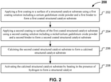
- FIG. 2 is a schematic illustration of a process 200 for producing a structured catalyst used in the pre-reforming process of the present invention.
- the process 200 includes application of a first coating to a surface of the structured catalyst substrate using a first coating solution including a cerium-gadolinium oxide powder and a first binder to form a first coated structured catalyst substrate.
- the structured catalyst substrate is a monolithic structured catalyst substrate.
- the structured catalyst substrate may be a porous geometric monolithic structured catalyst substrate, such as a cubic structure, as seen in FIG. 1A , or a hexagonal structure or any suitable geometric structure.
- the structured catalyst substrate can include a random porous monolithic structure.
- the structured catalyst substrate may be comprised of ceramic or metal or a combination thereof.
- the first binder may be comprised of a first polymeric material and the second binder is comprised of a second polymeric material.
- the first and second polymeric materials may be comprised of a polyvinyl butyral resin.
- the polyvinyl butyral resin may be Butvar ® type of resin such as Butvar-98.
- Any type of binder capable of binding a CGO powder to a surface may be used to bind the first coating to the structured catalyst substrate 102.
- Any type of binder capable of binding a nickel CGO powder to a CGO surface may be used to bind the second coating to the first coating.
- the process 200 can further include cleaning surfaces of the structured catalyst substrate before applying the first coating.
- An acid or other suitable solution may be used to remove impurities from surfaces of the structured catalyst.
- the cleaning of the surfaces of the structured catalyst substrate further can include washing the structured catalyst substrate with a 30% nitric acid solution and drying the structured catalyst substrate at 120 °C for at least one hour to provide a structured catalyst substrate having cleaned surfaces for receiving the first coating.
- the structured catalyst substrate can be subject to drying overnight, if required.
- application of the first coating can further include contacting the structured catalyst substrate with the first coating solution, removing excess amounts of the first coating solution to provide a film of the first coating solution on the structured catalyst substrate, and drying the film on the structured catalysts substrate.
- the processes of contacting, removing, and drying may be sequentially repeated at least five times to form the first coating on the structured catalyst substrate.
- the drying may be at 120 for at least one hour.
- the first coating solution may further include a solvent, a dispersant, and a plasticizer.
- the solvent can be a combination of two or more solvents, such as a mixture of 78% xylene and 22% butanol.
- the dispersant may be polyvinylpyrrolidone, and the plasticizer may be polyethylene glycol.
- the solvent may be any suitable solvent for application of the first coating.
- the dispersant may be any suitable dispersant for stabilizing the first coating solution.
- the plasticizer may be any suitable plasticizer for the first coating solution.
- the weight ratio of the various components in the first coating solution to the weight of the structured catalyst may be 4.0 for the CGO powder, 16.0 for the solvent, 0.2 for the dispersant, 0.2 for the plasticizer, and 0.16 for the binder.
- the process 200 can include application of a second coating to surfaces of the first coated structured catalyst substrate using a second coating solution including a nickel CGO powder and a second binder to form a second coated structured catalyst substrate.
- the first coating may enhance adhesion of the second coating.
- the second coating directly coating on the structured catalyst substrate may not have sufficient adhesion to surfaces of the structured catalyst substrate for practical use in a pre-reforming process.
- This second coating may delaminate and wash out without the first coating to provide adequate adhesion.
- the CGO coating may be referred to as a pre-coating layer.
- the pre-coating layer can prevent undesirable side reactions in a pre-reformer including the structured catalyst.
- application of the second coating can further include contacting the first coated structured catalyst substrate with the second coating solution, removing excess amounts of the second coating solution to provide a film of the second coating solution on the first coated structured catalyst substrate, and drying the film on the first coated structured catalyst substrate.
- the processes of contacting, removing, and drying may be sequentially repeated at least five times to form the second coating on the first coated structured catalyst substrate.
- the drying may be at 120 °C for at least one hour.
- the second coating solution further may include a solvent, a dispersant, and a plasticizer.
- the solvent can be a combination of two or more solvents, such as a mixture of 78% xylene and 22% butanol.
- the dispersant may be polyvinylpyrrolidone, and the plasticizer may be polyethylene glycol.
- the solvent may be any suitable solvent for application of the second coating.
- the dispersant may be any suitable dispersant for stabilizing the second coating solution.
- the plasticizer may be any suitable plasticizer for the second coating solution.
- the weight ratio of the various components in the second coating solution to the weight of the structured catalyst may be 4.0 for the nickel CGO powder, 16.0 for the solvent, 0.2 for the dispersant, 0.2 for the plasticizer, and 0.16 for the binder.
- the process 200 can include calcining the second coated structured catalyst substrate to form a calcined structured catalyst substrate.
- the calcining may further comprise heating in air at a temperature of 800-1100 °C for at least four hours, wherein the temperature of end temperature is reached by increasing the temperature over a period of six hours.
- the process 200 can include activating the calcined structured catalyst substrate by heating in the presence of hydrogen to form a structured catalyst.
- the activating further may comprise heating at a temperature of 500 °C for at least four hours in an atmosphere of 30% hydrogen and 70% nitrogen.
- the atmosphere can include a sufficient amount of hydrogen to activate the calcined structured catalyst substrate in combination with an optional gas having no or minimal impact on the activating.
- the optional gas may be an inert gas such as a noble gas for example.
- the nickel of the second coating may be in a non-active form nickel oxide before activating. The activating may convert the non-active form into an active form of nickel in the structured catalyst.
- FIG. 3 is a schematic illustration of a process 300 for pre-reforming a hydrocarbon fuel, in accordance with the present invention.
- the process 300 can include feeding to a catalytic pre-reformer air, steam, and a hydrocarbon fuel including C2 and greater hydrocarbons selected from the group consisting of natural gas, propane, gasoline, jet fuel, biofuel, diesel, and kerosene.
- the hydrocarbon fuel may be a diesel fuel having impurities within reasonable engineering tolerances.
- the catalytic pre-reforming may be a component of a SOFC and provides a synthetic gas containing methane to the SOFC.
- the process includes pre-reforming, in the catalytic pre-reformer, the hydrocarbon fuel to produce a reformate exit stream including hydrogen and methane, wherein the catalytic pre-reformer includes a structured catalyst having a structured catalyst substrate, a first coating applied to a surface of the structured catalyst substrate containing CGO, and a second coating applied to the first coating containing nickel CGC, in accordance with appended claim 1.
- the structured catalyst may include the structured catalyst of FIG. 1 , including the variously described embodiments disclosed in relation to FIG. 1 .
- FIG. 4 is a schematic illustration of a solid oxide fuel cell device 400 with a pre-reformer 402 including a structured catalyst, not according to the present invention.
- the device 400 may include the structured catalyst pre-reformer 402 to pre-reform a hydrocarbon fuel source 404 into a gas stream 406 including hydrogen and methane.
- the device 400 further may include a solid oxide fuel cell (SOFC) 408 in flow communication with the structured catalyst pre-reformer 402 to receive the gas stream 406.
- SOFC solid oxide fuel cell
- the device 400 may include an exhaust stream 410 to remove reactants from the SOFC 408.
- the structured catalyst pre-reformer 402 may include a structured catalyst with a structured catalyst substrate, a first coating applied to a surface of the structured catalyst substrate and including CGO, and a second coating applied to the first coating and including nickel CGO.
- the structured catalyst may include the structured catalyst of FIG. 1 , including the variously described embodiments disclosed in relation to FIG. 1 .
- Example 1 an experimental device is disclosed and described for testing the pre-reforming catalysts .
- FIG. 5 is a schematic illustration of an experimental system 500 for catalytic activity testing of pre-reforming catalysts.
- fuel from container 502 is pumped by a first high performance liquid chromatography (HPLC) pump 504 through a first check valve 506 and is atomized by an ultrasonic injector 518 by mixing with air from container 510 in mixer 508.
- the air from container 510 passes through a first mass flow controller 512, second check valve 514, and first ball valve 516.
- Atomized fuel with air passes through ultrasonic injector 518 to reactor 520.
- the reactor 520 is a pre-reformer and can be a diesel autothermal reformer as shown in FIG. 5 .
- Ultrasonic injector 518 includes pressure detecting gauge 521.
- Reactor 520 includes temperature detectors 522.
- the reactor 520 is made of 12.7 mm STS (stainless steel) tubes placed inside electric furnaces.
- the reactor 520 is controlled using PID temperature controllers and are monitored by thermocouples placed at the bottom of the catalytic bed, as indicated by temperature detectors 522.
- De-ionized water from container 524 (>15M ⁇ ) is supplied by a second HPLC pump 526.
- the first and second HPLC pumps are from MOLEH Co. Ltd.
- the water from container 524 is passed through a second check valve 530 and is supplied to a steam generator 528.
- a small quantity of nitrogen from container 532 is also fed into the steam generator 528 and ultrasonic-injector 518 to obtain a stable delivery of the reactants.
- the air from container 510 and nitrogen from container 532 are metered using mass flow controllers (MKS Co. Ltd.), as illustrated.
- the nitrogen from container 532 passes through a second mass flow controller 534, a third check valve 536, and then to the steam generator 528 to mix with water from container 534.
- the mixture passes through a valve 538 and then to the ultrasonic injector 518.
- the effluent from the reactor 520 passes through valve 540 with pressure detecting device 541, then through valve 542 and a vent via valve 544, then through a moisture trap 546 and then to a gas chromatograph (GC) 550 for sampling.
- GC gas chromatograph
- the GC 550 is gas equipped with a Thermal Conductivity Detector (TCD) and a Flame Ionization Detector (FID), which were used to analyze the composition of the effluent, also referred to as the diesel reformate in the case that diesel is the fuel.
- TCD Thermal Conductivity Detector
- FID Flame Ionization Detector
- the system of FIG. 5 was used for activity testing and analysis of various structured catalysts to design and optimize the structured catalysts. Activity test was used to compare the activity and stability of the structured catalysts. The spent catalysts were analyzed by scanning electron microscope to observe the morphological changes of the structured catalysts.
- Example 2 various embodiments of structured pre-reforming catalysts for diesel pre-reforming were prepared. Preparation methods included various pretreatments and compositions of the structured catalysts.
- the structured catalysts were designed to produce methane rich gas from diesel fuel.
- Various embodiments of the structured catalysts consisted of CGO pre-coating layer and a catalyst layer over the CGO pre-coating layer. For comparison, structured catalysts without a CGO pre-coating layer were prepared. Without being bound by theory, the CGO pre-coating layer enhances adhesion and prevents undesired reactions.
- the Ni-Ru/CGO catalyst layer was formed over the CGO pre-coating layer.
- a structured catalyst was prepared by washing a structured substrate with a solution of 30 % by weight of nitric acid to remove impurities from surfaces of the structured catalyst substrate.
- the structured substrate is as illustrated in FIG. 1A , prior to application of the coatings.
- the washed substrate was dried at 120 °C overnight.
- a CGO pre-coating slurry (first coating) was prepared by mixing the constituents in the proportions illustrated in Table 1 and then subjected to ball milling for 24 hours before coating the structured substrate.
- the structured substrate was coated by dipping into the first coating solution. Excess first coating solution was removed by blowing air across the structured substrate. The resulting coated structured substrate was dried at 120 °C for 1 hour. The process of dip coating, removing excess slurry, and drying were repeated for different structured substrates to provide structured substrates with different numbers of coating layers, and thus thicknesses, of the first coating.
- the various structured substrates were calcined in air at 800 °C for 4 hours. The temperature was ramped to 800 °C by 6 hours. TABLE 1.
- the various calcined structured substrates with the CGO coating were then coated with the second coating solution with the Ni-Ru/CGO based catalyst material.
- the coating process was the same as with the first CGO coating solution to provide a different number of coating layers of the Ni-Ru/CGO material.
- the resulting substrates were calcined in air at 800 °C for 4 hours. The temperature was ramped to 800 °C by 4 hours.
- FIGS. 1A and 1B SEM images of one of the various structured catalysts with two coatings are shown in FIGS. 1A and 1B .
- the thickness of total coating was less than approximately 10 ⁇ m for the structured catalyst shown in FIGS. 1A and 1B .
- the CGO pre-coating layer enhances adhesion of the Ni-Ru/CGO coating layer (second coating layer) and prevents undesired chemical reactions during diesel pre-reforming.
- Structured catalysts with and without the CGO pre-coating layer were tested for conversion percentage of diesel fuel in the pre-reforming device illustrated in FIG. 5 .
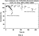
- FIG. 6 is a graphical representation of conversion of n-dodecane as a function of time for structured catalysts with and without the CGO pre-coating layer for a Ni-Ru/CGO catalyst coating, in accordance with various embodiments.
- Conversion CO + CO2 + CH4 production in mole basis / total carbon in fuel input
- Conversion CO + CO2 + CH4 production in mole basis / total carbon in fuel input
- the pre-reforming fuel used to simulate diesel fuel was n-dodecane.
- the water to carbon ratio was approximately three to one on mole basis.
- the temperature of operation of the pre-reforming was 500 °C.
- the gas hourly space velocity (GHSV) was 5000 per hour.
- GSHV is equal to the reactant gas flow rate divided by the reactor volume.
- the structured catalyst without the CGO pre-coating was degraded within 50 hours.
- the structured catalyst with the CGO pre-coating was successfully operated for 200 hours with high conversion rates and with 15.6 mole percent of CH 4 concentration, which indicates much better stability as a result of using the CGO pre-coating.
- FIGS. 7A and 7B are scanning electron microscopy (SEM) images of spent structured catalysts with and without a CGO pre-coating, in accordance with various embodiments.
- FIG. 7A is the structured catalyst without the CGO pre-coating.
- FIG. 7A the catalyst coating on the structured substrate is mostly removed, indicating a loss of catalytic activity of the structured catalyst.
- FIG. 7B is the structured catalyst with the CGO pre-coating.
- the catalyst coating remains adhered to the structured catalyst, indicating continued activity of the structured catalyst.
- the catalyst layer was washed out without CGO pre-coating.
- Ni-Ru/CGO-based catalyst expands and contracts repeatedly by redox and nickelcarbon (NiC) formation. This expansion and contraction accelerates the delamination of catalyst layer during pre-reforming process.
- NiC nickelcarbon
- the Ni-Ru/CGO coating layer remained on substrates after the test, which indicates that the delamination is prevented by the introduction of CGO pre-coating layer to provide stability to the coating.
- the Ni-Ru/CGO coating by itself is not as stable as when the pre-coating CGO layer is added to the structured catalyst.
- Example 3 various embodiments of the structured catalysts were prepared with different numbers of coating layers of CGO pre-coating and the Ni-Ru/CGO catalyst coating layer.
- the purpose of varying the coating layer was to optimize the number of layers for the structured catalysts.
- the purpose of optimizing the number of coating layers was to determine whether there is an optimum number of coating layers to reduce the cost and the time of preparation of various embodiments of the structured catalysts for pre-reforming.
- the thickness of coating layer was observed using scanning electron microscope (SEM).
- FIGS. 8A, 8B, and 8C schematically illustrate SEM images of three structured catalysts with five, seven, and nine layers of Ni-Ru/CGO coating layer respectively, in accordance with various embodiments.
- the thickness of the Ni-Ru/CGO coating layer was 6.0, 4.5, and 5.5 micrometers for coating layer numbers five, seven, and nine, respectively, as illustrated in FIGS. 8A, 8B, and 8C .
- Example 4 heat treatment of the CGO pre-coating layer was conducted at various temperatures to evaluate effect of heat on various embodiments of the structured catalysts.
- the substrate was heat treated before the Ni-Ru/CGO catalyst layer was added on top of the CGO pre-coating.
- the purpose of the heat treatment is to prevent removal of the CGO pre-coating layer during the addition of the Ni-Ru/CGO catalyst layer on top of the CGO pre-coating layer.
- the heat treatment temperature was varied to identify temperatures in which a stable CGO layer is formed on the structured substrate.
- FIGS. 9A, 9B, 9C, and 9D are scanning electron microscope images of structured substrates with CGO pre-coating followed by heat treatment at 800 °C, 900 °C, 1000 °C, and 1100 °C, respectively, in accordance with various embodiments.
- the CGO pre-coating is substantially adhered to the structured substrate at 800 °C treatment temperature.
- the CGO pre-coating layer becomes more delaminated from the structured substrate.
- the highest temperature of 1100 °C the CGO pre-coating appears to be mostly delaminated from the structured substrate. Accordingly, a heat treatment temperature of approximately 800 °C or less appears to provide a better CGO pre-coating layer for subsequent attachment of a Ni-Ru/CGO catalyst layer.
- Example 5 a comparison is made between an embodiment of the structured (monolith) catalysts and a non-structured (granular or granulated) catalyst in a pre-reforming reaction of n-dodecane fuel using the device of FIG. 1 .
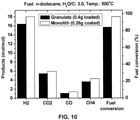
- FIG. 10 is a graphical representation of a comparison of a granular catalyst and a structured catalyst in a pre-reforming device, in accordance with various embodiments.
- the fuel used for the comparison was n-dodecane.
- the water to carbon ratio was three to one by mole basis.
- the temperature of the pre-reforming reaction was 500 °C.
- the Ni-Ru/CGO catalyst loaded on the granulated catalyst was 0.4 grams, and the Ni-Ru/CGO catalyst loaded on the monolith catalyst was 0.26 grams.
- the catalysts were loaded in the reactor separately and tested separately for conversion of n-dodecane in the pre-reforming reactor of FIG. 5 . The results in FIG.
- Ni-Ru/CGO catalyst 10 show that a significantly reduced amount of Ni-Ru/CGO catalyst was utilized when using the structured catalysts in comparison to the granulated catalyst.
- the structured monolith catalyst approximately 97% of n-dodecane was converted to synthetic gas.
- fuel conversion was less than 90% for the granulated catalyst, approximately 84%.
- the superiority of the structured catalyst likely is due to a higher mass transfer coefficient in comparison to the granulated catalyst.
- consumption of the Ni-Ru/CGO catalyst amount may be reduced by approximately at least 35% when using the structured catalyst instead of the granulated catalyst.
- Ranges may be expressed in this disclosure as from about one particular value, and/or to about another particular value. When such a range is expressed, it is to be understood that another embodiment is from the one particular value and/or to the other particular value, along with all combinations within said range.
Landscapes
- Chemical & Material Sciences (AREA)
- Chemical Kinetics & Catalysis (AREA)
- Engineering & Computer Science (AREA)
- Organic Chemistry (AREA)
- Materials Engineering (AREA)
- Health & Medical Sciences (AREA)
- General Health & Medical Sciences (AREA)
- Combustion & Propulsion (AREA)
- Inorganic Chemistry (AREA)
- Manufacturing & Machinery (AREA)
- Life Sciences & Earth Sciences (AREA)
- Sustainable Development (AREA)
- Sustainable Energy (AREA)
- Electrochemistry (AREA)
- General Chemical & Material Sciences (AREA)
- Physics & Mathematics (AREA)
- Thermal Sciences (AREA)
- Catalysts (AREA)
- Hydrogen, Water And Hydrids (AREA)
- Organic Low-Molecular-Weight Compounds And Preparation Thereof (AREA)
Claims (3)
- Verfahren zur Vorreformierung eines Kohlenwasserstoffbrennstoffs, Folgendes umfassend:Einspeisen von Luft, Dampf und einem Kohlenwasserstoffbrennstoff, einschließend C2 und größere Kohlenwasserstoffe in einen katalytischen Vorreformer, wobei der Kohlenwasserstoffbrennstoff aus der Gruppe ausgewählt ist, bestehend aus Erdgas, Propan, Benzin, Flugbenzin, Biokraftstoff, Diesel und Kerosin; undVorreformieren, in dem katalytischen Vorreformer, des Kohlenwasserstoffbrennstoffs zum Erzeugen eines Reformat-Ausgangsstroms, welcher Wasserstoff und Methan einschließt,wobei der katalytische Vorreformer einen strukturierten Katalysator einschließt, welcher ein Substrat für einen strukturierten Katalysator aufweist,wobei das Substrat für einen strukturierten Katalysator ein monolithisch strukturiertes Katalysatorsubstrat ist, wobei eine erste Beschichtung Cerium-Gadoliniumoxid enthält, wobei die erste Beschichtung eine Vorbeschichtung ist und an einer Oberfläche des strukturierten Katalysatorsubstrates aufgebracht ist; und wobei eine zweite Beschichtung Nickel und Cerium-Gadoliniumoxid enthält, wobei die zweite Beschichtung eine aktive Katalysatorschicht ist und auf der ersten Beschichtung aufgebracht ist.
- Verfahren nach Anspruch 1, wobei die zweite Beschichtung des strukturierten Katalysators ferner Ruthenium enthält.
- Verfahren nach Anspruch 1 oder 2, wobei der strukturierte Katalysator zwei oder mehr Schichten der zweiten Beschichtung enthält.
Applications Claiming Priority (2)
| Application Number | Priority Date | Filing Date | Title |
|---|---|---|---|
| US15/408,892 US20180200695A1 (en) | 2017-01-18 | 2017-01-18 | Structured catalysts for pre-reforming hydrocarbons |
| PCT/US2018/014143 WO2018136587A1 (en) | 2017-01-18 | 2018-01-18 | Structured catalysts for pre-reforming hydrocarbons |
Publications (2)
| Publication Number | Publication Date |
|---|---|
| EP3558520A1 EP3558520A1 (de) | 2019-10-30 |
| EP3558520B1 true EP3558520B1 (de) | 2022-03-09 |
Family
ID=61257095
Family Applications (1)
| Application Number | Title | Priority Date | Filing Date |
|---|---|---|---|
| EP18706586.7A Active EP3558520B1 (de) | 2017-01-18 | 2018-01-18 | Verfahren zur vorreformierung eines kohlenwasserstoffhaltigen kraftstoffes in gegenwart eines strukturierten katalysators |
Country Status (7)
| Country | Link |
|---|---|
| US (2) | US20180200695A1 (de) |
| EP (1) | EP3558520B1 (de) |
| JP (1) | JP6823183B2 (de) |
| KR (1) | KR102248896B1 (de) |
| CN (1) | CN110740811A (de) |
| SG (1) | SG11201905877PA (de) |
| WO (1) | WO2018136587A1 (de) |
Families Citing this family (2)
| Publication number | Priority date | Publication date | Assignee | Title |
|---|---|---|---|---|
| US10953388B1 (en) * | 2019-12-27 | 2021-03-23 | Saudi Arabian Oil Company | Ni—Ru—CgO based pre-reforming catalyst for liquid hydrocarbons |
| CN118215537A (zh) * | 2021-09-03 | 2024-06-18 | 蓝氧科技有限股份公司 | 具有新颖组合物的hdv即用型电化学电极、结构体和制造方法 |
Citations (3)
| Publication number | Priority date | Publication date | Assignee | Title |
|---|---|---|---|---|
| EP2031675A1 (de) * | 2007-08-31 | 2009-03-04 | Technical University of Denmark | Auf Ceroxid und Edelstahl basierende Elektroden |
| US20120024757A1 (en) * | 2010-07-13 | 2012-02-02 | Zetao Xia | Method for forming a catalyst comprising catalytic nanoparticles and a catalyst support |
| WO2014190148A1 (en) * | 2013-05-22 | 2014-11-27 | Saudi Arabian Oil Company | Ni/cgo and ni-ru/cgo based pre-reforming catalysts formulation for methane rich gas production from diesel processing for fuel cell applications |
Family Cites Families (10)
| Publication number | Priority date | Publication date | Assignee | Title |
|---|---|---|---|---|
| US7732084B2 (en) * | 2004-02-04 | 2010-06-08 | General Electric Company | Solid oxide fuel cell with internal reforming, catalyzed interconnect for use therewith, and methods |
| JP4795949B2 (ja) * | 2005-03-23 | 2011-10-19 | 株式会社日本触媒 | 固体酸化物形燃料電池用燃料極材料およびそれを用いた燃料極、並びに燃料電池セル |
| US7455923B2 (en) * | 2006-09-01 | 2008-11-25 | Fuelcell Energy, Inc. | Fuel supply assembly for supplying propane fuel to a fuel cell assembly and fuel cell system employing same |
| CN101293207A (zh) * | 2007-04-24 | 2008-10-29 | 中国科学院大连化学物理研究所 | 一种含稀土元素的固体氧化物燃料电池阳极催化材料 |
| FR2945378B1 (fr) * | 2009-05-11 | 2011-10-14 | Commissariat Energie Atomique | Cellule de pile a combustible haute temperature a reformage interne d'hydrocarbures. |
| JP4872027B1 (ja) * | 2010-11-01 | 2012-02-08 | 日本碍子株式会社 | 固体酸化物型燃料電池 |
| JP2012156098A (ja) * | 2011-01-28 | 2012-08-16 | Mitsubishi Materials Corp | 固体酸化物形燃料電池の発電セルの燃料極構造 |
| JP5746309B2 (ja) * | 2012-12-17 | 2015-07-08 | サムソン エレクトロ−メカニックス カンパニーリミテッド. | 固体酸化物燃料電池の電極用ペースト、これを用いる固体酸化物燃料電池およびその製造方法 |
| CN104084211B (zh) * | 2014-07-10 | 2017-01-11 | 山西潞安矿业(集团)有限责任公司 | 用于制合成气或者制氢的催化剂及其制法和应用 |
| KR20170123100A (ko) * | 2016-04-28 | 2017-11-07 | 한국과학기술원 | 디젤자열개질 촉매 제조방법 및 이에 의하여 제조된 디젤자열개질 촉매 |
-
2017
- 2017-01-18 US US15/408,892 patent/US20180200695A1/en not_active Abandoned
-
2018
- 2018-01-18 CN CN201880007525.4A patent/CN110740811A/zh active Pending
- 2018-01-18 SG SG11201905877PA patent/SG11201905877PA/en unknown
- 2018-01-18 KR KR1020197023804A patent/KR102248896B1/ko active Active
- 2018-01-18 JP JP2019538469A patent/JP6823183B2/ja not_active Expired - Fee Related
- 2018-01-18 WO PCT/US2018/014143 patent/WO2018136587A1/en not_active Ceased
- 2018-01-18 EP EP18706586.7A patent/EP3558520B1/de active Active
-
2021
- 2021-02-11 US US17/174,255 patent/US20210162374A1/en not_active Abandoned
Patent Citations (3)
| Publication number | Priority date | Publication date | Assignee | Title |
|---|---|---|---|---|
| EP2031675A1 (de) * | 2007-08-31 | 2009-03-04 | Technical University of Denmark | Auf Ceroxid und Edelstahl basierende Elektroden |
| US20120024757A1 (en) * | 2010-07-13 | 2012-02-02 | Zetao Xia | Method for forming a catalyst comprising catalytic nanoparticles and a catalyst support |
| WO2014190148A1 (en) * | 2013-05-22 | 2014-11-27 | Saudi Arabian Oil Company | Ni/cgo and ni-ru/cgo based pre-reforming catalysts formulation for methane rich gas production from diesel processing for fuel cell applications |
Non-Patent Citations (1)
| Title |
|---|
| CHUNCHUAN XU ET AL: "An H2S-Tolerant Ni-GDC Anode with a GDC Barrier Layer", JOURNAL OF THE ELECTROCHEMICAL SOCIETY, vol. 158, no. 11, 1 January 2011 (2011-01-01), pages B1405, XP055461894, ISSN: 0013-4651, DOI: 10.1149/2.067111jes * |
Also Published As
| Publication number | Publication date |
|---|---|
| KR102248896B1 (ko) | 2021-05-07 |
| JP2020505224A (ja) | 2020-02-20 |
| EP3558520A1 (de) | 2019-10-30 |
| SG11201905877PA (en) | 2019-08-27 |
| US20180200695A1 (en) | 2018-07-19 |
| CN110740811A (zh) | 2020-01-31 |
| KR20200017380A (ko) | 2020-02-18 |
| WO2018136587A1 (en) | 2018-07-26 |
| US20210162374A1 (en) | 2021-06-03 |
| JP6823183B2 (ja) | 2021-01-27 |
Similar Documents
| Publication | Publication Date | Title |
|---|---|---|
| US20030219637A1 (en) | Direct hydrocarbon reforming in protonic ceramic fuel cells by electrolyte steam permeation | |
| US20150263366A1 (en) | Paper-structured catalyst, paper-structured catalyst array body, and solid oxide fuel cell provided with paper-structured catalyst or paper-structured catalyst array body | |
| US20210162374A1 (en) | Structured catalysts for pre-reforming hydrocarbons | |
| US20090215911A1 (en) | Structured catalyst bed and method for conversion of feed materials to chemical products and liquid fuels | |
| Liao et al. | In situ reduction of a CuO/ZnO/CeO2/ZrO2 catalyst washcoat supported on Al2O3 foam ceramic by glycerol for methanol steam reforming in a microreactor | |
| Smorygo et al. | Structured catalyst supports and catalysts for the methane indirect internal steam reforming in the intermediate temperature SOFC | |
| WO2006088936A2 (en) | Precious metal water-gas shift catalyst with oxide support modified with rare earth elements | |
| US9809453B2 (en) | Catalysts for hydrocarbon reforming | |
| Yan et al. | Improvement of solid oxide fuel cell performance by a core‐shell structured catalyst using low concentration coal bed methane fuel | |
| KR101365787B1 (ko) | Pt-Re 바이메탈 수성 가스 전환 촉매를 위한 공정조건 | |
| Galletti et al. | CO preferential oxidation in H2-rich gas for fuel cell applications: Microchannel reactor performance with Rh-based catalyst | |
| US20060213813A1 (en) | Method and structure for desulfurizing gasoline or diesel fuel for use in a fuel cell power plant | |
| US7842634B2 (en) | Blended catalyst with improved performance | |
| Vernoux | Recent advances in electrochemical promotion of catalysis | |
| US9876244B2 (en) | Systems and methods for steam reforming | |
| Shin et al. | Anodic Reaction in Syngas‐Fueled Proton‐Conducting Solid Oxide Fuel Cells | |
| KR101420630B1 (ko) | 화석연료 개질을 위한 연료전지용 지지체 개질촉매 및 그 제조방법 | |
| WO2005068071A1 (ja) | 触媒、触媒の製造方法、酸化方法、酸化用物体および酸化装置 | |
| KR101202538B1 (ko) | 세라믹 보드를 이용한 선택적 산화 반응기 | |
| Bae et al. | Metal-supported solid oxide fuel cell with diesel reformer | |
| WO2012057727A1 (en) | Adsorber assembly | |
| Smith et al. | Catalytic Material Development for a SOFC Reforming System: Application of an Oxidative Steam Reforming Catalyst to a Monolithic Reactor | |
| Hunt | III. B. 5 Diesel Plasma Reformer | |
| KR20140048386A (ko) | 모노리스 연료전지 자열개질반응 촉매 | |
| KR20090109725A (ko) | 세라믹 보드를 이용한 개질 반응 시스템 |
Legal Events
| Date | Code | Title | Description |
|---|---|---|---|
| STAA | Information on the status of an ep patent application or granted ep patent |
Free format text: STATUS: UNKNOWN |
|
| STAA | Information on the status of an ep patent application or granted ep patent |
Free format text: STATUS: THE INTERNATIONAL PUBLICATION HAS BEEN MADE |
|
| PUAI | Public reference made under article 153(3) epc to a published international application that has entered the european phase |
Free format text: ORIGINAL CODE: 0009012 |
|
| STAA | Information on the status of an ep patent application or granted ep patent |
Free format text: STATUS: REQUEST FOR EXAMINATION WAS MADE |
|
| 17P | Request for examination filed |
Effective date: 20190723 |
|
| AK | Designated contracting states |
Kind code of ref document: A1 Designated state(s): AL AT BE BG CH CY CZ DE DK EE ES FI FR GB GR HR HU IE IS IT LI LT LU LV MC MK MT NL NO PL PT RO RS SE SI SK SM TR |
|
| AX | Request for extension of the european patent |
Extension state: BA ME |
|
| RIN1 | Information on inventor provided before grant (corrected) |
Inventor name: BAE, MINSEOK Inventor name: LEE, SANGHA Inventor name: KATIKANENI, SAI, P. Inventor name: BAE, JOONGMYEON |
|
| DAV | Request for validation of the european patent (deleted) | ||
| DAX | Request for extension of the european patent (deleted) | ||
| PUAG | Search results despatched under rule 164(2) epc together with communication from examining division |
Free format text: ORIGINAL CODE: 0009017 |
|
| STAA | Information on the status of an ep patent application or granted ep patent |
Free format text: STATUS: EXAMINATION IS IN PROGRESS |
|
| 17Q | First examination report despatched |
Effective date: 20201013 |
|
| B565 | Issuance of search results under rule 164(2) epc |
Effective date: 20201013 |
|
| RIC1 | Information provided on ipc code assigned before grant |
Ipc: B01J 23/89 20060101ALI20201008BHEP Ipc: C01B 3/26 20060101ALI20201008BHEP Ipc: B01J 35/04 20060101ALI20201008BHEP Ipc: C01B 3/40 20060101ALI20201008BHEP Ipc: B01J 37/00 20060101ALI20201008BHEP Ipc: B01J 23/83 20060101ALI20201008BHEP Ipc: B01J 37/02 20060101AFI20201008BHEP Ipc: B01J 23/00 20060101ALI20201008BHEP Ipc: B01J 37/18 20060101ALI20201008BHEP |
|
| GRAP | Despatch of communication of intention to grant a patent |
Free format text: ORIGINAL CODE: EPIDOSNIGR1 |
|
| STAA | Information on the status of an ep patent application or granted ep patent |
Free format text: STATUS: GRANT OF PATENT IS INTENDED |
|
| INTG | Intention to grant announced |
Effective date: 20211001 |
|
| GRAS | Grant fee paid |
Free format text: ORIGINAL CODE: EPIDOSNIGR3 |
|
| GRAA | (expected) grant |
Free format text: ORIGINAL CODE: 0009210 |
|
| STAA | Information on the status of an ep patent application or granted ep patent |
Free format text: STATUS: THE PATENT HAS BEEN GRANTED |
|
| RAP3 | Party data changed (applicant data changed or rights of an application transferred) |
Owner name: KOREA ADVANCED INSTITUTE OF SCIENCE AND TECHNOLOGY Owner name: SAUDI ARABIAN OIL COMPANY |
|
| AK | Designated contracting states |
Kind code of ref document: B1 Designated state(s): AL AT BE BG CH CY CZ DE DK EE ES FI FR GB GR HR HU IE IS IT LI LT LU LV MC MK MT NL NO PL PT RO RS SE SI SK SM TR |
|
| REG | Reference to a national code |
Ref country code: CH Ref legal event code: EP Ref country code: AT Ref legal event code: REF Ref document number: 1473675 Country of ref document: AT Kind code of ref document: T Effective date: 20220315 |
|
| REG | Reference to a national code |
Ref country code: IE Ref legal event code: FG4D |
|
| REG | Reference to a national code |
Ref country code: DE Ref legal event code: R096 Ref document number: 602018031933 Country of ref document: DE |
|
| REG | Reference to a national code |
Ref country code: NL Ref legal event code: FP |
|
| REG | Reference to a national code |
Ref country code: LT Ref legal event code: MG9D |
|
| PG25 | Lapsed in a contracting state [announced via postgrant information from national office to epo] |
Ref country code: SE Free format text: LAPSE BECAUSE OF FAILURE TO SUBMIT A TRANSLATION OF THE DESCRIPTION OR TO PAY THE FEE WITHIN THE PRESCRIBED TIME-LIMIT Effective date: 20220309 Ref country code: RS Free format text: LAPSE BECAUSE OF FAILURE TO SUBMIT A TRANSLATION OF THE DESCRIPTION OR TO PAY THE FEE WITHIN THE PRESCRIBED TIME-LIMIT Effective date: 20220309 Ref country code: NO Free format text: LAPSE BECAUSE OF FAILURE TO SUBMIT A TRANSLATION OF THE DESCRIPTION OR TO PAY THE FEE WITHIN THE PRESCRIBED TIME-LIMIT Effective date: 20220609 Ref country code: LT Free format text: LAPSE BECAUSE OF FAILURE TO SUBMIT A TRANSLATION OF THE DESCRIPTION OR TO PAY THE FEE WITHIN THE PRESCRIBED TIME-LIMIT Effective date: 20220309 Ref country code: HR Free format text: LAPSE BECAUSE OF FAILURE TO SUBMIT A TRANSLATION OF THE DESCRIPTION OR TO PAY THE FEE WITHIN THE PRESCRIBED TIME-LIMIT Effective date: 20220309 Ref country code: BG Free format text: LAPSE BECAUSE OF FAILURE TO SUBMIT A TRANSLATION OF THE DESCRIPTION OR TO PAY THE FEE WITHIN THE PRESCRIBED TIME-LIMIT Effective date: 20220609 |
|
| REG | Reference to a national code |
Ref country code: AT Ref legal event code: MK05 Ref document number: 1473675 Country of ref document: AT Kind code of ref document: T Effective date: 20220309 |
|
| PG25 | Lapsed in a contracting state [announced via postgrant information from national office to epo] |
Ref country code: LV Free format text: LAPSE BECAUSE OF FAILURE TO SUBMIT A TRANSLATION OF THE DESCRIPTION OR TO PAY THE FEE WITHIN THE PRESCRIBED TIME-LIMIT Effective date: 20220309 Ref country code: GR Free format text: LAPSE BECAUSE OF FAILURE TO SUBMIT A TRANSLATION OF THE DESCRIPTION OR TO PAY THE FEE WITHIN THE PRESCRIBED TIME-LIMIT Effective date: 20220610 Ref country code: FI Free format text: LAPSE BECAUSE OF FAILURE TO SUBMIT A TRANSLATION OF THE DESCRIPTION OR TO PAY THE FEE WITHIN THE PRESCRIBED TIME-LIMIT Effective date: 20220309 |
|
| PG25 | Lapsed in a contracting state [announced via postgrant information from national office to epo] |
Ref country code: SM Free format text: LAPSE BECAUSE OF FAILURE TO SUBMIT A TRANSLATION OF THE DESCRIPTION OR TO PAY THE FEE WITHIN THE PRESCRIBED TIME-LIMIT Effective date: 20220309 Ref country code: SK Free format text: LAPSE BECAUSE OF FAILURE TO SUBMIT A TRANSLATION OF THE DESCRIPTION OR TO PAY THE FEE WITHIN THE PRESCRIBED TIME-LIMIT Effective date: 20220309 Ref country code: RO Free format text: LAPSE BECAUSE OF FAILURE TO SUBMIT A TRANSLATION OF THE DESCRIPTION OR TO PAY THE FEE WITHIN THE PRESCRIBED TIME-LIMIT Effective date: 20220309 Ref country code: PT Free format text: LAPSE BECAUSE OF FAILURE TO SUBMIT A TRANSLATION OF THE DESCRIPTION OR TO PAY THE FEE WITHIN THE PRESCRIBED TIME-LIMIT Effective date: 20220711 Ref country code: ES Free format text: LAPSE BECAUSE OF FAILURE TO SUBMIT A TRANSLATION OF THE DESCRIPTION OR TO PAY THE FEE WITHIN THE PRESCRIBED TIME-LIMIT Effective date: 20220309 Ref country code: EE Free format text: LAPSE BECAUSE OF FAILURE TO SUBMIT A TRANSLATION OF THE DESCRIPTION OR TO PAY THE FEE WITHIN THE PRESCRIBED TIME-LIMIT Effective date: 20220309 Ref country code: CZ Free format text: LAPSE BECAUSE OF FAILURE TO SUBMIT A TRANSLATION OF THE DESCRIPTION OR TO PAY THE FEE WITHIN THE PRESCRIBED TIME-LIMIT Effective date: 20220309 Ref country code: AT Free format text: LAPSE BECAUSE OF FAILURE TO SUBMIT A TRANSLATION OF THE DESCRIPTION OR TO PAY THE FEE WITHIN THE PRESCRIBED TIME-LIMIT Effective date: 20220309 |
|
| PG25 | Lapsed in a contracting state [announced via postgrant information from national office to epo] |
Ref country code: PL Free format text: LAPSE BECAUSE OF FAILURE TO SUBMIT A TRANSLATION OF THE DESCRIPTION OR TO PAY THE FEE WITHIN THE PRESCRIBED TIME-LIMIT Effective date: 20220309 Ref country code: IS Free format text: LAPSE BECAUSE OF FAILURE TO SUBMIT A TRANSLATION OF THE DESCRIPTION OR TO PAY THE FEE WITHIN THE PRESCRIBED TIME-LIMIT Effective date: 20220709 Ref country code: AL Free format text: LAPSE BECAUSE OF FAILURE TO SUBMIT A TRANSLATION OF THE DESCRIPTION OR TO PAY THE FEE WITHIN THE PRESCRIBED TIME-LIMIT Effective date: 20220309 |
|
| REG | Reference to a national code |
Ref country code: DE Ref legal event code: R097 Ref document number: 602018031933 Country of ref document: DE |
|
| PLBE | No opposition filed within time limit |
Free format text: ORIGINAL CODE: 0009261 |
|
| STAA | Information on the status of an ep patent application or granted ep patent |
Free format text: STATUS: NO OPPOSITION FILED WITHIN TIME LIMIT |
|
| PG25 | Lapsed in a contracting state [announced via postgrant information from national office to epo] |
Ref country code: DK Free format text: LAPSE BECAUSE OF FAILURE TO SUBMIT A TRANSLATION OF THE DESCRIPTION OR TO PAY THE FEE WITHIN THE PRESCRIBED TIME-LIMIT Effective date: 20220309 |
|
| 26N | No opposition filed |
Effective date: 20221212 |
|
| PG25 | Lapsed in a contracting state [announced via postgrant information from national office to epo] |
Ref country code: SI Free format text: LAPSE BECAUSE OF FAILURE TO SUBMIT A TRANSLATION OF THE DESCRIPTION OR TO PAY THE FEE WITHIN THE PRESCRIBED TIME-LIMIT Effective date: 20220309 |
|
| P01 | Opt-out of the competence of the unified patent court (upc) registered |
Effective date: 20230526 |
|
| PG25 | Lapsed in a contracting state [announced via postgrant information from national office to epo] |
Ref country code: IT Free format text: LAPSE BECAUSE OF FAILURE TO SUBMIT A TRANSLATION OF THE DESCRIPTION OR TO PAY THE FEE WITHIN THE PRESCRIBED TIME-LIMIT Effective date: 20220309 |
|
| REG | Reference to a national code |
Ref country code: DE Ref legal event code: R119 Ref document number: 602018031933 Country of ref document: DE |
|
| REG | Reference to a national code |
Ref country code: CH Ref legal event code: PL |
|
| PG25 | Lapsed in a contracting state [announced via postgrant information from national office to epo] |
Ref country code: LU Free format text: LAPSE BECAUSE OF NON-PAYMENT OF DUE FEES Effective date: 20230118 |
|
| REG | Reference to a national code |
Ref country code: BE Ref legal event code: MM Effective date: 20230131 |
|
| PG25 | Lapsed in a contracting state [announced via postgrant information from national office to epo] |
Ref country code: LI Free format text: LAPSE BECAUSE OF NON-PAYMENT OF DUE FEES Effective date: 20230131 Ref country code: DE Free format text: LAPSE BECAUSE OF NON-PAYMENT OF DUE FEES Effective date: 20230801 Ref country code: CH Free format text: LAPSE BECAUSE OF NON-PAYMENT OF DUE FEES Effective date: 20230131 |
|
| PG25 | Lapsed in a contracting state [announced via postgrant information from national office to epo] |
Ref country code: BE Free format text: LAPSE BECAUSE OF NON-PAYMENT OF DUE FEES Effective date: 20230131 |
|
| PG25 | Lapsed in a contracting state [announced via postgrant information from national office to epo] |
Ref country code: IE Free format text: LAPSE BECAUSE OF NON-PAYMENT OF DUE FEES Effective date: 20230118 |
|
| PGFP | Annual fee paid to national office [announced via postgrant information from national office to epo] |
Ref country code: NL Payment date: 20240123 Year of fee payment: 7 |
|
| PGFP | Annual fee paid to national office [announced via postgrant information from national office to epo] |
Ref country code: GB Payment date: 20240123 Year of fee payment: 7 |
|
| PGFP | Annual fee paid to national office [announced via postgrant information from national office to epo] |
Ref country code: FR Payment date: 20240123 Year of fee payment: 7 |
|
| PG25 | Lapsed in a contracting state [announced via postgrant information from national office to epo] |
Ref country code: MC Free format text: LAPSE BECAUSE OF FAILURE TO SUBMIT A TRANSLATION OF THE DESCRIPTION OR TO PAY THE FEE WITHIN THE PRESCRIBED TIME-LIMIT Effective date: 20220309 |
|
| PG25 | Lapsed in a contracting state [announced via postgrant information from national office to epo] |
Ref country code: MC Free format text: LAPSE BECAUSE OF FAILURE TO SUBMIT A TRANSLATION OF THE DESCRIPTION OR TO PAY THE FEE WITHIN THE PRESCRIBED TIME-LIMIT Effective date: 20220309 |
|
| PG25 | Lapsed in a contracting state [announced via postgrant information from national office to epo] |
Ref country code: CY Free format text: LAPSE BECAUSE OF FAILURE TO SUBMIT A TRANSLATION OF THE DESCRIPTION OR TO PAY THE FEE WITHIN THE PRESCRIBED TIME-LIMIT; INVALID AB INITIO Effective date: 20180118 |
|
| PG25 | Lapsed in a contracting state [announced via postgrant information from national office to epo] |
Ref country code: HU Free format text: LAPSE BECAUSE OF FAILURE TO SUBMIT A TRANSLATION OF THE DESCRIPTION OR TO PAY THE FEE WITHIN THE PRESCRIBED TIME-LIMIT; INVALID AB INITIO Effective date: 20180118 |
|
| REG | Reference to a national code |
Ref country code: NL Ref legal event code: MM Effective date: 20250201 |
|
| GBPC | Gb: european patent ceased through non-payment of renewal fee |
Effective date: 20250118 |
|
| PG25 | Lapsed in a contracting state [announced via postgrant information from national office to epo] |
Ref country code: NL Free format text: LAPSE BECAUSE OF NON-PAYMENT OF DUE FEES Effective date: 20250201 |
|
| PG25 | Lapsed in a contracting state [announced via postgrant information from national office to epo] |
Ref country code: GB Free format text: LAPSE BECAUSE OF NON-PAYMENT OF DUE FEES Effective date: 20250118 |
|
| PG25 | Lapsed in a contracting state [announced via postgrant information from national office to epo] |
Ref country code: FR Free format text: LAPSE BECAUSE OF NON-PAYMENT OF DUE FEES Effective date: 20250131 |
|
| PG25 | Lapsed in a contracting state [announced via postgrant information from national office to epo] |
Ref country code: TR Free format text: LAPSE BECAUSE OF FAILURE TO SUBMIT A TRANSLATION OF THE DESCRIPTION OR TO PAY THE FEE WITHIN THE PRESCRIBED TIME-LIMIT Effective date: 20220309 |