EP3558209B1 - Hilfsvorrichtung zur handrehabilitation - Google Patents
Hilfsvorrichtung zur handrehabilitation Download PDFInfo
- Publication number
- EP3558209B1 EP3558209B1 EP17885397.4A EP17885397A EP3558209B1 EP 3558209 B1 EP3558209 B1 EP 3558209B1 EP 17885397 A EP17885397 A EP 17885397A EP 3558209 B1 EP3558209 B1 EP 3558209B1
- Authority
- EP
- European Patent Office
- Prior art keywords
- user
- forearm
- emg
- platform
- wrist
- Prior art date
- Legal status (The legal status is an assumption and is not a legal conclusion. Google has not performed a legal analysis and makes no representation as to the accuracy of the status listed.)
- Active
Links
- 238000002567 electromyography Methods 0.000 claims description 121
- 210000003811 finger Anatomy 0.000 claims description 106
- 210000000245 forearm Anatomy 0.000 claims description 93
- 210000003205 muscle Anatomy 0.000 claims description 42
- 210000000707 wrist Anatomy 0.000 claims description 40
- 230000033001 locomotion Effects 0.000 claims description 35
- 210000003813 thumb Anatomy 0.000 claims description 27
- 238000012549 training Methods 0.000 claims description 25
- 230000007935 neutral effect Effects 0.000 claims description 19
- 238000012545 processing Methods 0.000 claims description 16
- 210000001364 upper extremity Anatomy 0.000 claims description 9
- 238000000034 method Methods 0.000 description 23
- 230000009471 action Effects 0.000 description 9
- 230000005540 biological transmission Effects 0.000 description 7
- 238000004458 analytical method Methods 0.000 description 6
- 230000004118 muscle contraction Effects 0.000 description 5
- 238000005259 measurement Methods 0.000 description 4
- 208000006011 Stroke Diseases 0.000 description 3
- 210000003414 extremity Anatomy 0.000 description 3
- 230000001934 delay Effects 0.000 description 2
- 238000001514 detection method Methods 0.000 description 2
- 238000011161 development Methods 0.000 description 2
- 230000006872 improvement Effects 0.000 description 2
- 230000007257 malfunction Effects 0.000 description 2
- 230000010355 oscillation Effects 0.000 description 2
- 206010033799 Paralysis Diseases 0.000 description 1
- 230000004913 activation Effects 0.000 description 1
- 230000001154 acute effect Effects 0.000 description 1
- 238000005452 bending Methods 0.000 description 1
- 230000008859 change Effects 0.000 description 1
- 230000001684 chronic effect Effects 0.000 description 1
- 230000000295 complement effect Effects 0.000 description 1
- 239000012141 concentrate Substances 0.000 description 1
- 238000011217 control strategy Methods 0.000 description 1
- 238000005516 engineering process Methods 0.000 description 1
- 239000000835 fiber Substances 0.000 description 1
- 210000004247 hand Anatomy 0.000 description 1
- 238000001727 in vivo Methods 0.000 description 1
- 230000010354 integration Effects 0.000 description 1
- 230000003993 interaction Effects 0.000 description 1
- 210000004932 little finger Anatomy 0.000 description 1
- 229910044991 metal oxide Inorganic materials 0.000 description 1
- 150000004706 metal oxides Chemical class 0.000 description 1
- 230000001537 neural effect Effects 0.000 description 1
- 229920000642 polymer Polymers 0.000 description 1
- 230000035484 reaction time Effects 0.000 description 1
- 230000004043 responsiveness Effects 0.000 description 1
- 239000000523 sample Substances 0.000 description 1
- 239000004065 semiconductor Substances 0.000 description 1
- 230000035807 sensation Effects 0.000 description 1
- 230000001148 spastic effect Effects 0.000 description 1
- 230000021542 voluntary musculoskeletal movement Effects 0.000 description 1
- 210000003857 wrist joint Anatomy 0.000 description 1
Images


Classifications
-
- A—HUMAN NECESSITIES
- A61—MEDICAL OR VETERINARY SCIENCE; HYGIENE
- A61H—PHYSICAL THERAPY APPARATUS, e.g. DEVICES FOR LOCATING OR STIMULATING REFLEX POINTS IN THE BODY; ARTIFICIAL RESPIRATION; MASSAGE; BATHING DEVICES FOR SPECIAL THERAPEUTIC OR HYGIENIC PURPOSES OR SPECIFIC PARTS OF THE BODY
- A61H1/00—Apparatus for passive exercising; Vibrating apparatus ; Chiropractic devices, e.g. body impacting devices, external devices for briefly extending or aligning unbroken bones
- A61H1/02—Stretching or bending or torsioning apparatus for exercising
- A61H1/0274—Stretching or bending or torsioning apparatus for exercising for the upper limbs
- A61H1/0285—Hand
- A61H1/0288—Fingers
-
- A—HUMAN NECESSITIES
- A61—MEDICAL OR VETERINARY SCIENCE; HYGIENE
- A61F—FILTERS IMPLANTABLE INTO BLOOD VESSELS; PROSTHESES; DEVICES PROVIDING PATENCY TO, OR PREVENTING COLLAPSING OF, TUBULAR STRUCTURES OF THE BODY, e.g. STENTS; ORTHOPAEDIC, NURSING OR CONTRACEPTIVE DEVICES; FOMENTATION; TREATMENT OR PROTECTION OF EYES OR EARS; BANDAGES, DRESSINGS OR ABSORBENT PADS; FIRST-AID KITS
- A61F5/00—Orthopaedic methods or devices for non-surgical treatment of bones or joints; Nursing devices; Anti-rape devices
- A61F5/01—Orthopaedic devices, e.g. splints, casts or braces
- A61F5/0102—Orthopaedic devices, e.g. splints, casts or braces specially adapted for correcting deformities of the limbs or for supporting them; Ortheses, e.g. with articulations
- A61F5/013—Orthopaedic devices, e.g. splints, casts or braces specially adapted for correcting deformities of the limbs or for supporting them; Ortheses, e.g. with articulations for the arms, hands or fingers
-
- A—HUMAN NECESSITIES
- A61—MEDICAL OR VETERINARY SCIENCE; HYGIENE
- A61H—PHYSICAL THERAPY APPARATUS, e.g. DEVICES FOR LOCATING OR STIMULATING REFLEX POINTS IN THE BODY; ARTIFICIAL RESPIRATION; MASSAGE; BATHING DEVICES FOR SPECIAL THERAPEUTIC OR HYGIENIC PURPOSES OR SPECIFIC PARTS OF THE BODY
- A61H1/00—Apparatus for passive exercising; Vibrating apparatus ; Chiropractic devices, e.g. body impacting devices, external devices for briefly extending or aligning unbroken bones
- A61H1/02—Stretching or bending or torsioning apparatus for exercising
- A61H1/0274—Stretching or bending or torsioning apparatus for exercising for the upper limbs
-
- A—HUMAN NECESSITIES
- A61—MEDICAL OR VETERINARY SCIENCE; HYGIENE
- A61F—FILTERS IMPLANTABLE INTO BLOOD VESSELS; PROSTHESES; DEVICES PROVIDING PATENCY TO, OR PREVENTING COLLAPSING OF, TUBULAR STRUCTURES OF THE BODY, e.g. STENTS; ORTHOPAEDIC, NURSING OR CONTRACEPTIVE DEVICES; FOMENTATION; TREATMENT OR PROTECTION OF EYES OR EARS; BANDAGES, DRESSINGS OR ABSORBENT PADS; FIRST-AID KITS
- A61F5/00—Orthopaedic methods or devices for non-surgical treatment of bones or joints; Nursing devices; Anti-rape devices
- A61F5/01—Orthopaedic devices, e.g. splints, casts or braces
- A61F5/0102—Orthopaedic devices, e.g. splints, casts or braces specially adapted for correcting deformities of the limbs or for supporting them; Ortheses, e.g. with articulations
- A61F2005/0132—Additional features of the articulation
- A61F2005/0144—Multibar
-
- A—HUMAN NECESSITIES
- A61—MEDICAL OR VETERINARY SCIENCE; HYGIENE
- A61F—FILTERS IMPLANTABLE INTO BLOOD VESSELS; PROSTHESES; DEVICES PROVIDING PATENCY TO, OR PREVENTING COLLAPSING OF, TUBULAR STRUCTURES OF THE BODY, e.g. STENTS; ORTHOPAEDIC, NURSING OR CONTRACEPTIVE DEVICES; FOMENTATION; TREATMENT OR PROTECTION OF EYES OR EARS; BANDAGES, DRESSINGS OR ABSORBENT PADS; FIRST-AID KITS
- A61F5/00—Orthopaedic methods or devices for non-surgical treatment of bones or joints; Nursing devices; Anti-rape devices
- A61F5/01—Orthopaedic devices, e.g. splints, casts or braces
- A61F5/0102—Orthopaedic devices, e.g. splints, casts or braces specially adapted for correcting deformities of the limbs or for supporting them; Ortheses, e.g. with articulations
- A61F2005/0132—Additional features of the articulation
- A61F2005/0155—Additional features of the articulation with actuating means
-
- A—HUMAN NECESSITIES
- A61—MEDICAL OR VETERINARY SCIENCE; HYGIENE
- A61H—PHYSICAL THERAPY APPARATUS, e.g. DEVICES FOR LOCATING OR STIMULATING REFLEX POINTS IN THE BODY; ARTIFICIAL RESPIRATION; MASSAGE; BATHING DEVICES FOR SPECIAL THERAPEUTIC OR HYGIENIC PURPOSES OR SPECIFIC PARTS OF THE BODY
- A61H2201/00—Characteristics of apparatus not provided for in the preceding codes
- A61H2201/16—Physical interface with patient
- A61H2201/1602—Physical interface with patient kind of interface, e.g. head rest, knee support or lumbar support
- A61H2201/1635—Hand or arm, e.g. handle
- A61H2201/1638—Holding means therefor
-
- A—HUMAN NECESSITIES
- A61—MEDICAL OR VETERINARY SCIENCE; HYGIENE
- A61H—PHYSICAL THERAPY APPARATUS, e.g. DEVICES FOR LOCATING OR STIMULATING REFLEX POINTS IN THE BODY; ARTIFICIAL RESPIRATION; MASSAGE; BATHING DEVICES FOR SPECIAL THERAPEUTIC OR HYGIENIC PURPOSES OR SPECIFIC PARTS OF THE BODY
- A61H2201/00—Characteristics of apparatus not provided for in the preceding codes
- A61H2201/50—Control means thereof
- A61H2201/5058—Sensors or detectors
- A61H2201/5061—Force sensors
-
- A—HUMAN NECESSITIES
- A61—MEDICAL OR VETERINARY SCIENCE; HYGIENE
- A61H—PHYSICAL THERAPY APPARATUS, e.g. DEVICES FOR LOCATING OR STIMULATING REFLEX POINTS IN THE BODY; ARTIFICIAL RESPIRATION; MASSAGE; BATHING DEVICES FOR SPECIAL THERAPEUTIC OR HYGIENIC PURPOSES OR SPECIFIC PARTS OF THE BODY
- A61H2201/00—Characteristics of apparatus not provided for in the preceding codes
- A61H2201/50—Control means thereof
- A61H2201/5058—Sensors or detectors
- A61H2201/5064—Position sensors
-
- A—HUMAN NECESSITIES
- A61—MEDICAL OR VETERINARY SCIENCE; HYGIENE
- A61H—PHYSICAL THERAPY APPARATUS, e.g. DEVICES FOR LOCATING OR STIMULATING REFLEX POINTS IN THE BODY; ARTIFICIAL RESPIRATION; MASSAGE; BATHING DEVICES FOR SPECIAL THERAPEUTIC OR HYGIENIC PURPOSES OR SPECIFIC PARTS OF THE BODY
- A61H2205/00—Devices for specific parts of the body
- A61H2205/06—Arms
- A61H2205/065—Hands
- A61H2205/067—Fingers
-
- A—HUMAN NECESSITIES
- A61—MEDICAL OR VETERINARY SCIENCE; HYGIENE
- A61H—PHYSICAL THERAPY APPARATUS, e.g. DEVICES FOR LOCATING OR STIMULATING REFLEX POINTS IN THE BODY; ARTIFICIAL RESPIRATION; MASSAGE; BATHING DEVICES FOR SPECIAL THERAPEUTIC OR HYGIENIC PURPOSES OR SPECIFIC PARTS OF THE BODY
- A61H2230/00—Measuring physical parameters of the user
- A61H2230/60—Muscle strain, i.e. measured on the user, e.g. Electromyography [EMG]
- A61H2230/605—Muscle strain, i.e. measured on the user, e.g. Electromyography [EMG] used as a control parameter for the apparatus
Definitions
- the present invention relates to a power assistive device for hand rehabilitation that provides training of finger flexion-extension and forearm supination-pronation to a user.
- Power assistive devices have been widely used for hand rehabilitation. These devices often include a single sensor and provide training in a single degree of freedom. It may not be efficient and effective to use these devices to perform different types of training exercises.
- CN 102274107 A provides an exoskeleton training mechanical hand for rehabilitation and using method thereof.
- the present invention is directed to a power assistive device for hand rehabilitation that provides training of a combined movement of finger flexion-extension and forearm supination-pronation to a user according to claim 1.
- the power assistive device includes a hand brace and a base.
- the hand brace in use attaches to a hand of the user and includes a plurality of finger driving units that adjustably connect to a platform and that in use attach to fingers of the user, a plurality of actuators that connect to the finger driving units and that actuate the finger driving units, and a plurality of force sensors that connect to the finger driving units and the bottom of the hand brace and that detect force signals generated by movement of the hand brace.
- the base removably connects to the hand brace and includes a supporting structure that is located on a proximal end of the base and that supports a forearm of the user, a forearm rotator that abuts the forearm support and that includes a plurality of C-shaped tracks formed along an inner surface of the Forearm rotator, a rotatable platform that moves along the C-shaped tracks and that in use receives a forearm of the user, a mounting platform that connects to and extends from a distal end of the rotatable platform and that removably mounts the hand brace onto the base, and an electromyography (EMG) sensor that in use attaches to the forearm of the user and that senses EMG signals generated by movement of the upper limb of the user, in which the EMG signals and the force signals are used to provide the training of the finger flexion-extension and the forearm supination-pronation to the user.
- EMG electromyography
- Example embodiments relate to apparatus and method that provide training of finger flexion-extension and forearm supination-pronation to a user. The methods do not form part of the claimed invention.
- EMG surface electromyography
- MMG mechanomyography
- Reaction time measurement as a very relevant measurement parameter in robotics should be measured with a precise detection of muscle contraction onset, which can be made possible with integration of three sensors, e.g., EMG sensors, MMG sensors, and force sensors.
- three sensors e.g., EMG sensors, MMG sensors, and force sensors.
- EMG sensors EMG sensors
- MMG sensors MMG sensors
- force sensors force sensors.
- even much larger time delays can be considered as an onset once the reliability (particularly Inter-Correlation-Coefficient) or repeatability without significant differences between measurements is shown to be under influence of many external factors.
- An example embodiment includes a hand rehabilitation system that provides training of flexion-extension of fingers and supination-pronation of a forearm to a user.
- the system includes a hand brace, a base that removably connects to the hand brace, and an EMG sensor that in use attaches to either or both of an upper arm and a forearm of the user and senses EMG signals generated by the user.
- the hand brace is wearable by the user and includes an external platform and an internal platform that connects to the external platform.
- the hand brace includes a MMG sensor that attaches to either or both of an upper arm and forearm of the user and senses MMG signals generated by the user.
- the hand brace includes finger driving units, actuators that connect to the finger driving units and actuate the finger driving units, force sensors that connect to the finger driving units and the bottom of the hand brace and detect force signals generated by movement of the hand brace.
- the base includes a supporting structure located on a proximal end of the base, a forearm rotator abuts the supporting structure and includes C-shaped tracks formed along an inner surface of the forearm rotator, a rotatable platform that runs along the C-shaped tracks, and a mounting platform that connects to and extends from a distal end of the rotatable platform.
- the rotatable platform in use receives and supports a forearm of the user by a mounting platform that removably receives the hand brace such that the hand brace removably mounts on the base.
- the processing unit receives and analyses the EMG signals the force signals to determine an onset time of muscle dynamics of the upper limb of the user, so as to provide the training to the user.
- the processing unit receives and analyses the EMG signals, the MMG signals, and the force signals to determine an onset time of muscle dynamics of the upper limb of the user, so as to provide the training to the user.
- the rotatable platform rotates between a maximum supination position and a maximum pronation position.
- the rotatable platform supinates from a neutral position (i.e. a position where a thumb of the user faces upwards and is regarded as 0 degree) to a maximum of 45 degrees of supination (to an outer side) with respect to the neutral position at the maximum supination position.
- the rotatable platform pronates from the neutral position to a maximum of 90 degrees of pronation (to an inner side) with respect to the neutral position at the maximum pronation position.
- the forearm base further includes a locking knob that screwably connects to the mounting platform. Further, the locking knob adjustably mounts the hand brace onto the mounting platform to fix a wrist of the user at three different positions when the user wears the hand brace and puts the forearm on the rotatable platform.
- the wrist when the wrist is fixed at a first wrist extension position, the wrist rests at a neutral position of 0 degrees with respect to a longitudinal axis of the forearm of the user.
- the wrist when the wrist is fixed at a second wrist extension position, the wrist extends 15 degrees with respect to the longitudinal axis.
- the wrist When the wrist is fixed at a third wrist extension position, the wrist extends 30 degrees with respect to the longitudinal axis.
- the base includes a position tracking sensor that tracks a movement route of the user on moving the base.
- the base includes an emergency stop button that enables the user to stop the base from operation to protect the user in case any unexpected malfunction of any part of the base.
- the system includes a wireless receiver that receives commands from a smartphone, tablet, or other portable electronic device.
- commands include actuating the finger driving unit for bending and extending fingers of the user, and rotating the rotatable platform along the C-shaped track for supinating and pronating the forearm of the user.
- the EMG sensor is an EMG-MMG sensor that includes two EMG electrodes and a MMG sensor.
- the two EMG sensors are 20 millimeters (20 mm) apart and sense the EMG signals.
- the MMG sensor locates between the two EMG electrodes and senses MMG signals.
- a method to determine an onset time of muscle dynamics involves implementation of three different sensors, namely an EMG sensors, an MMG sensors, and a force sensors.
- An EMG onset time, an MMG onset time and a force onset time are determined from EMG signals sensed by the EMG sensors, MMG signals sensed by the MMG sensors and force signals sensed by the force sensors respectively.
- Time delays between the EMG onset times, the MMG onset times and the force onset times are then calculated and an average point will be considered as a real onset time of muscle dynamics, while voluntary movement is intended to be generated by the user.
- EMG sensors there are two EMG sensors applied in which one of the EMG sensors senses EMG signals for finger flexion and the other EMG sensor senses EMG signals for finger extension.
- MMG sensors there are also two MMG sensors applied in which one of the MMG sensors senses MMG signals for finger flexion and the other MMG sensor senses MMG signals for finger extension.
- force sensors there are five force sensors applied in which each of the force sensors senses force signals of each of the fingers of the user.
- EMG sensors there are two EMG sensors applied in which one of the EMG sensors senses EMG signals for forearm supination and the other EMG sensor senses EMG signals for forearm pronation.
- MMG sensors there are also two MMG sensors applied in which one of the MMG sensors senses MMG signals for forearm supination and the other MMG sensor senses MMG signals for forearm pronation.
- force sensors there are five force sensors applied in which each of the force sensors senses force signals of each of the fingers of the user.
- T0 is a time when an external stimulus applies to the system.
- T1 is an onset time of muscle dynamics and determined by a time averaged between the EMG onset time and the force onset time.
- T1 the onset time of muscle dynamics, is determined by either a first average time between the EMG onset time and the force onset time, or a second average time between the MMG onset time and the force onset time.
- the choice of using either the first average time or the second average time as T1 depends on whether the EMG signals or the MMG signals are sensed first. If the EMG signals are sensed first, the first average time will be T1, while in case the MMG signals are sensed first, the second average time will be T1. By way of example, EMG signals are generally sensed earlier than the MMG signals.
- T2 is an onset time of muscle force threshold and is determined when the force exceeds a force threshold, for example, 5 Newtons (N) or 10 N.
- RFD is the rate of change or development of the force calculated starting from the force onset time to the force threshold.
- an EMG signal threshold and/or a force signal threshold can be set as the muscle force threshold.
- the EMG signal muscle force threshold is set as the muscle force threshold at an acute stage after stroke.
- the force signal threshold is set as the muscle force threshold at a more chronic stage after stroke or when marked improvement can be seen and the patient is able to steer the force, for example, to manipulate an object.
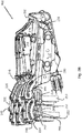
- FIGS 1A- 1C show a power assistive device 100 (hereinafter the "device") that is used for hand rehabilitation in accordance with an example embodiment.
- the device 100 includes a hand brace 102 that removably connects to a base 104.
- hand rehabilitation includes training of finger flexion-extension and forearm supination-pronation.
- the device 100 is driven by electromyography (EMG) signals of the affected limb of the user, in which the EMG signals reflect an intention of the user to move the affected limb.
- EMG electromyography
- the hand brace 102 mounts on the base 104 at an inclination angle of ten degrees with respect to an axis X as shown in Figure 1C . Under this inclination angle, a user can place his hand on the base in a natural position with minimal stress to his wrist joint on wearing the device 100.
- FIGS 2A - 2D show a hand brace 200 of the device in accordance with an example embodiment.
- the hand brace 200 includes an external platform 202, an internal platform 204 that connects to an inner surface of the external platform 202, a plurality of finger driving units 206 that adjustably connect to the external platform 202 and the internal platform 204, a plurality of actuators 208 that moveably connect to the finger driving units 206, a plurality of actuator bases 210 that are fixed on an outer surface of the external platform 202 and connects to the actuators 208, and a side fixation bracket 212 that adjustably connect to the external platform 202 and the internal platform 204.
- the hand brace includes five finger driving units that adjustably connect to the external platform and the internal platform, five actuators that moveably connect to the five finger driving units respectively, and five actuator bases that are fixed on the outer surface of the external platform and connect to the five actuators respectively.
- the five actuators actuate the five finger driving units respectively.
- a dorsal side of a hand of the user is in contact with an inner side of the internal platform 204.
- the internal platform 204 can be of different sizes to accommodate palms with different sizes.
- the finger driving unit 206 movably mounts on the inner surface of the external platform 202 and extends outwardly from a distal end 214 of the external platform 202.
- the finger driving unit 206 includes an intermediate rail guide 224 at the distal end 214, a proximal rail guide 226 at a proximal end 220, an intermediate follower assembly 216 that connects the intermediate rail guide 224 and the proximal rail guide 226, and a proximal follower assembly 218 that connects the proximal rail guide 226 to the actuator 208.
- a front finger follower 256 connects to the intermediate follower assembly 216.
- the intermediate follower assembly 216 and the proximal follower assembly 218, respectively, ensures a controlled and proportioned angular rotation in a restricted range of a proximal interphalangeal (PIP) joint and a metacarpophalangeal (MCP) joint of the user, such that a movement and responsiveness of the hand brace 200 resembles a cohesive movement of a human finger specifically for hand opening action and hand grasping action.
- PIP proximal interphalangeal
- MCP metacarpophalangeal
- a force sensor 232 is disposed on the front finger follower 256.
- each of the intermediate rail guide 224 and the proximal rail guide 226 has an arc-shaped track 228.
- Bearings 230 are movably disposed within the track 228 so that the front finger follower 256 as driven by the intermediate follower assembly 216 and the proximal follower assembly 218, respectively, follow a path of the intermediate rail guide 224 along the track 228 and a path of the proximal rail guide 226 along the track 228.
- a rotational range of the intermediate rail guide 224 and a rotational range of the proximal rail guide 226 are different, such that the intermediate follower assembly 216 and the proximal follower assembly 218 generate a proportional relationship between the intermediate rail guide 224 and the proximal rail guide 226.
- the hand brace 200 has a linkage assembly 222 that connects the intermediate follower assembly 216 and the proximal rail guide 226.
- an intermediate strap holder 246 connects to a bottom side of the front finger follower 256, and a proximal strap holder 248 connects to a bottom side of the intermediate rail guide 224 and a bottom side of the proximal follower assembly 218.
- the intermediate strap holder 246 adjustably fixes a finger strap 250 through a strap position adjustable slot 252 that is disposed within a cavity of the intermediate strap holder 246.
- the proximal strap holder 248 adjustably fixes a finger strap 250 through a strap position adjustable slot 252 that is disposed within a cavity of the proximal strap holder 248.
- the intermediate strap holder 246 and the proximal strap holder 248 are made of soft pad. The finger strap 250 warps around the finger of the user to hold the finger within the finger driving unit 206 and keep the finger in contact while the finger driving unit 206 is moving.
- the actuator 208 has a proximal end that connects to proximal end 220 of the external platform 202 through the actuator bases 210, and a distal end that connects to the proximal follower assembly 218.
- a longitudinal motion of the actuator 208 is translated into an angular/rotational motion that causes relative rotation of the proximal follower assembly 218 along the track 228 of the proximal rail guide 226.
- the rotational movement of the proximal follower assembly 218 then actuates a rotational movement of the intermediate rail guide 224 in which when the intermediate rail guide 224 rotates, the intermediate follower assembly 216 rotates and pushes the front finger follower 256 to rotate along the track 228.
- the hand brace 200 has a thumb platform 234 that is formed separately or integrally with the external platform 202.
- the thumb driving unit 236 adjustably connects to the thumb platform 234 at different positions to match different thumb lengths, different web sizes between the thumb and an index finger of the user.
- the thumb driving unit 236 includes a thumb rail guide 238, a thumb follower assembly 240 that connects the thumb rail guide 238 to the actuator 208.
- the thumb rail guide 238 has an arc-shaped thumb rail track 242.
- Thumb bearings 244 are moveably disposed within the thumb rail track 242 so that the thumb follower assembly 240 follow a path of the thumb rail guide 238 along the thumb rail track 242.
- a thumb strap holder 254 connects to a bottom side of the thumb rail guide 238 and adjustably fixes a finger strap 250 through a strap position adjustable slot 252 that is disposed within a cavity of the thumb strap holder 254.
- the thumb strap holder 254 is made of a soft pad.
- the actuator base 210 fixes onto the external platform 202 by, for example a screw set, at one end, and connects to the actuator 208 at the other end via, for example a hinge joint, at the other end.
- the actuator base 210 facilitates a proper alignment of the actuator 208, such that the actuator 208 and the finger driving unit 206 are properly aligned.
- the side fixation bracket 212 adjustably connects to a little finger side of the external platform 202 at different lateral positions to match different palm sizes.
- the force sensor 232 measures a resultant force generated by the finger of the user.
- the resultant force generated has a range of magnitude of 0 - 50 N.
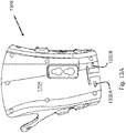
- FIGS 3A - 3C show a base (or a forearm base) 300 of the device in accordance with an example embodiment.
- the base 300 includes a supporting structure 302, a forearm rotator 304 that abuts the supporting structure 302, a rotatable platform 306, and a mounting platform 308.
- the supporting structure 302 locates at a proximal end 310 of the base 300 and in use receives a forearm of the user.
- a forearm strap 312 is adjustably located near an opening of the supporting structure 302. Once the forearm of the user is placed on the supporting structure 302, the forearm strap 312 can wrap around an upper surface of the forearm so as to secure the forearm onto the supporting structure 302.
- the forearm rotator 304 abuts the supporting structure 302 and includes a track(s) formed along an inner surface of the forearm rotator 304 for the rotatable platform 306 to move therealong.
- the forearm rotator 304 includes a first C-shaped track 314 and a second C-shaped track 316 that are formed along an inner surface of the forearm rotator 304.
- the rotatable platform 306 moves along the first C-shaped track 314 and the second C-shaped track 316 and in use receives a forearm of the user.
- the rotatable platform 306 moves in a clockwise direction to demonstrate a pronation action of the wrist, while an anti-clockwise movement of the rotatable platform 306 demonstrates a supination action of the wrist.
- the forearm rotator can have more than two tracks that are formed along the inner surface of the forearm rotator for the rotatable platform to move therealong.
- the rotatable platform 306 moves between a maximum supination position and a maximum pronation position.
- the maximum supination position and the maximum pronation position can be set by the user according to his/her needs.
- the maximum supination position is pre-set at a position 45 degrees clockwise from a neutral position of (i.e. a position where a thumb of the user faces upwards and is regarded as 0 degree), and the maximum pronation position is pre-set at a position 90 degrees anti-clockwise from the neutral position of 0 degree.
- the rotatable platform 306 supinates (i.e. moves in a clockwise direction for a right hand) from a neutral position (i.e.
- the rotatable platform 306 pronates (i.e. moves in an anti-clockwise direction for a right hand) from the neutral position up to 90 degrees with respect to the neutral position of the base 300 at the maximum pronation position.
- the rotatable platform 306 can move clockwise from 0 to 90 degrees to demonstrate pronation of the wrist between 0 and 90 degrees, and can move anti-clockwise from o to 45 degrees to demonstrate supination of the wrist between 0 and 45 degrees.
- the mounting platform 308 connects to and extends from a distal end 318 of the rotatable platform 306 and removably mounts a hand brace onto the base 300.
- the mounting platform 308 is an L-shaped plate.
- a locking knob 320 removably connects to and securely locks at the mounting platform 308 at an extended end 322 of the mounting platform 308.
- the locking knob 320 inserts into a hole on the extended end 322 of the mounting platform 308 to removably connect to the mounting platform 308.
- the locking knob can have threads that match internal threads on a hole of the mounting platform, so that the locking knob can screwably connect to and securely locks at the mounting platform.
- the locking knob 320 adjustably mounts a hand brace of the device onto the mounting platform 308 and fixes a wrist of the user at different positions when the user is undergoing a training of finger extension and finger flexion.
- the locking knob 320 fixes the wrist at three different positions.
- the wrist When the wrist is fixed at a first wrist extension position, the wrist rests at a neutral position of 0 degree with respect to a longitudinal axis of a forearm of the user.
- the wrist When the wrist is fixed at a second wrist extension position, the wrist extends 15 degrees with respect to the longitudinal axis of the forearm.
- the wrist When the wrist is fixed at a third wrist extension position, the wrist extends 30 degrees with respect to the longitudinal axis of the forearm.
- the emergency stop button 326 is provided on a side of the base 300 and enables the user to stop the base 300 from operation to protect the user in case any unexpected malfunction of any part of the base 300.
- a rechargeable battery 330 is removably provided on the distal end 318 of the base 300.
- the rechargeable battery 330 upon a full recharge, the rechargeable battery 330 enables the base 300 to run for four hours continuously.
- the rechargeable battery is a lithium-polymer battery.
- Figure 3D shows a bottom plate 328 of the base 300.
- a plurality of bearing rollers 324 and a position tracking sensor 332 are provided on the bottom plate 328 of the base 300.
- Bearing rollers 324 allow the base 300 to move smoothly on a surface where the base 300 sits on.
- the position tracking sensor 332 tracks a route of movement of the user on using the base 300.
- the position tracking sensor 332 is a complementary metal oxide semiconductor (CMOS) sensor for position tracking so that the user is able to move over an area on using the base 300.
- CMOS complementary metal oxide semiconductor
- the power assistive device 100 includes an actuator positioning controller that controls a speed of supination and pronation (i.e. a speed of the rotatable platform), so that a cycle time of supination/pronation is the same as a cycle time of flexion/extension to achieve synchronization between the finger driving units 106 and the rotatable platform 108.
- the action of flexion or extension will stop and the finger driving units will return to an opposite direction in order to avoid any damages to the user and to the device 100.
- a next cycle of finger flexion/extension and forearm supination/pronation will not start until both movements of the finger flexion/extension and forearm supination/pronation have completed.
- synchronization between the finger driving units 106 and the rotatable platform 108 can be attained and no time shift between the two movements of the finger flexion/extension and forearm supination/pronation after several cycles can be ensured.
- FIG. 4A shows a user that wears the device 400 in accordance with an example embodiment.
- Two electromyography (EMG) sensors 402A - 402B removably attach to a forearm of the user.
- EMG electromyography
- the EMG sensor 402A removably attaches to a flexor digitorum muscle
- EMG sensor 402B removably attaches to an extensor digitorum muscle.
- FIG. 4B shows a user that wears the device 400 in accordance with another example embodiment.
- An electromyography (EMG) sensor 402A attaches to an upper arm of the user while 402B sensor attaches to a forearm of the user.
- EMG electromyography
- the EMG sensor 402A removably attaches to a Biceps Brachii muscle and EMG sensor 402B removably attaches to either flexor digitorum, extensor digitorum or pronator teres muscle in the forearm.
- each of the EMG sensors 402A and 402B includes two EMG electrodes that are opposite in polarity.
- the two EMG electrodes sense either finger flexion or finger extension if they are located on the forearm or if they belong to the EMG sensor 402A or the EMG sensor 402B.
- the two EMG electrodes sense either forearm supination or forearm pronation if one of them is located on the upper arm and other one is located on the forearm, or if they belong to the EMG sensor 402A or the EMG sensor 402B.
- the two electrodes of the EMG sensor 402A do not detect different motions of the hand, and the two electrodes of the EMG sensor 402B do not detect different motions of the hand.
- the EMG sensors are electromyography-mechanomyography (EMG-MMG) sensors that include two EMG electrodes and a MMG sensor.
- the two EMG electrodes are separate from each other by 20 millimeters (mm) and sense EMG signals.
- the MMG sensor is located between the two EMG electrodes and senses MMG signals.
- one of the EMG electrodes senses EMG signals for finger flexion and the other EMG electrode senses EMG signals for finger extension.
- one of the EMG electrodes senses EMG signals for forearm supination and the other EMG electrode senses EMG signal for forearm pronation.
- the MMG sensor includes two MMG electrodes in which one of the MMG electrodes senses MMG signals for finger flexion and the other MMG electrode senses MMG signals for finger extension.
- one of the MMG sensor includes two MMG electrodes in which one of the MMG electrodes senses MMG signals for forearm supination and the other MMG electrode senses MMG signals for forearm pronation.
- a reference electrode can be mounted over an elbow of the user and provides a common reference to inputs of the two EMG electrodes.
- the EMG sensors 402A - 402B detect EMG signals generated by movement of a upper limb of the user. EMG signals from an affected muscle of a limb correspond to an intention of the user and can control an assistive motion provided by the device 400. As such, the user can actively participate in a training of a combined movement of finger flexion-extension and forearm supination-pronation. By way of example, the user can maintain finger flexion/extension while he supinates/pronates his forearm in the same training. If the user can maintain finger extension while supinating, flexor or spastic pattern is improved.
- the EMG sensors are EMG-MMG sensors that also detect MMG signals generated by movement of a hand of the user.
- the actions of finger flexion, finger extension, forearm supination and forearm pronation can be combined in any forms and in any consequences per a demand and a need of the user.
- FIG. 5 shows an electronic system 500 that includes the device 502 that communicates with a handheld portable electronic device (HPED) 516 via one or more network(s) 518 accordance with an example embodiment.
- the device 502 includes a hand brace 503 that removably connects to a base 504, an EMG sensor 506, a force sensor 508, a processing unit 510, a memory 512, and a transmitter/receiver 514.
- the processing unit 510 communicates with the hand brace 503 and the base 504, and receives EMG signals from the EMG sensor 506, and receives force signals from the force sensor 508.
- the EMG signals and the force signals are transmitted to the processing unit 510 in real time during training.
- the processing unit 510 analyses the EMG signals and the force signals to determine an onset time of muscle dynamics of a hand of the user.
- the processing unit 510 also communicates with the memory 512 and the transmitter/receiver 514.
- the memory 512 stores the EMG signals the force signals, and the onset time of muscle dynamics, and records movement histories of the hand brace 503 and the base 504.
- the EMG sensor is an EMG-MMG sensor that senses both EMG signals and MMG signals.
- the EMG signals, the MMG signals and the force signals are transmitted to the processing unit in real time during training.
- the processing unit analyzes the EMG signals, the MMG signals and the force signals to determine an onset time of muscle dynamics of a hand of the user.
- the memory stores the EMG signals, the MMG signals, the force signals, and the onset time of muscle dynamics, and records movement histories of the hand brace and the base.
- the transmitter/receiver 514 wirelessly receives commands from the HPED 516 to operate the device 502 for providing training of a combined movement of finger flexion-extension and forearm supination-pronation to the user.
- the transmitter/receiver 514 receives commands form the HPED to actuate finger driving units of the hand brace 503 to provide a training of finger flexion and finger extension to the user.
- the transmitter/receiver 514 receives commands form the HPED to move a rotatable platform of the base 504 to provide a training of forearm supination and forearm pronation to the user.
- the rotatable platform moves along C-shaped tracks of the base 504.
- the HPED 516 (such as a smartphone, a tablet computer, a laptop, or other computer) can include a memory 528, a display 520, a device manager 522, a transmitter/receiver 524, and a processing unit 526.
- the memory 518 stores the information transmitted from the device 502.
- the information includes the EMG signals, the MMG signals, the force signals, the onset time of muscle dynamics, and a profile of the user.
- the display 520 displays the information and the device manager 522 (such as a software application) enables the user to communicate with the device 502, such as making commands to provide a training of finger flexion-extension and/or a training of forearm supination-pronation to the user.
- the transmitter/receiver 524 wirelessly transmits commands from the HPED to the device 502, and receives information stored in the memory 512 of the device 502.
- FIG. 6 shows a method executed by a hand rehabilitation system to determine an onset time of muscle dynamics, not forming part of the claimed invention.
- Electromyography (EMG) signals of a hand of a user are sensed by an EMG sensor in a power assistive device in the hand rehabilitation system in box 602.
- Force signals of a finger of the hand of the user are sensed by a force sensor in the power assistive device in the hand rehabilitation system in box 604.
- the hand rehabilitation system calculates an EMG onset time from the EMG signals and a force onset time from the force signals in box 606.
- the hand rehabilitation system analyses the EMG onset time, and the force onset time to calculate the onset time of muscle dynamics in box 608.
- mechanomyography (MMG) signals of the hand of the user are sensed by an MMG sensor in the power assistive device in the hand rehabilitation system.
- the hand rehabilitation system calculates an EMG onset time from the EMG signals, an MMG onset time from the MMG signals, and a force onset time from the force signals.
- the hand rehabilitation system analyses the EMG onset time, the MMG onset time, and the force onset time to calculate the onset time of muscle dynamics.
- Figure 7 shows a method to calculate an onset time of muscle dynamics in a hand rehabilitation system, not forming part of the claimed invention.
- the onset time of muscle dynamics is identified as the time averaged between an EMG onset time and a force onset timecalculated by the hand rehabilitation system in box 702.
- a first average value between an EMG onset time and a force onset time is calculated by the hand rehabilitation system.
- a second average value between an MMG onset time and the force onset time is calculated by the hand rehabilitation system.
- the first average value is determined, by the hand rehabilitation system, to be the onset time of muscle dynamics if a first EMG signal is sensed earlier than a first MMG signal.
- the second average value is determined, by the hand rehabilitation system, to be the onset time of muscle dynamics if the first MMG signal is sensed earlier than the first EMG signal.
- Figure 8 shows a method to determine an EMG onset time in a hand rehabilitation system, not forming part of the claimed invention.
- the hand rehabilitation system calculates a value of three standard deviations (SD) for EMG signals from the EMG signals sensed by an EMG sensor in box 802.
- the hand rehabilitation system determines an EMG onset signal when an EMG signal reaches the three SD for EMG signals in box 804.
- the hand rehabilitation system determines the EMG onset time by identifying a time at which the EMG onset signal is sensed in box 806.
- Figure 9 shows a method to determine a force onset time in a hand rehabilitation system, not forming part of the claimed invention.
- the hand rehabilitation system calculates a value of three standard deviations (SD) for force signals from the force signals sensed by a force sensor in box 902.
- the hand rehabilitation system determines a force onset signal when a force signal reaches the three SD for force signals in box 904.
- the hand rehabilitation system determines the force onset time by identifying a time at which the force onset signal is sensed in box 906.
- a method to determine an MMG onset time in a hand rehabilitation system calculates a value of three standard deviations (SD) for MMG signals from the MMG signals sensed by an MMG sensor.
- SD standard deviations
- the hand rehabilitation system determines an MMG onset signal when a MMG signal reaches the three SD for MMG signals.
- the hand rehabilitation system determines the MMG onset time by identifying a time at which the MMG onset signal is sensed.
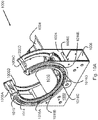
- Figures 10A to 10D show an internal structure of a forearm rotator 1000 in accordance with an example embodiment.
- the forearm rotator 1000 includes a front plate 1002 and a back plate 1004 connects to the front plate 1002 through connecting rods 1006A - 1006F and a U-shaped connecting plate 1008.
- a first C-shaped track 1010 is disposed on the front plate 1002 and includes a first rotary track 1014.
- a second C-shaped track 1012 is disposed on the back plate 1004 and includes a second rotary track 1020.
- Rotary bearings 1016A to 1016E are movably disposed within the first rotary track 1014 and the second rotary track 1020 to facilitate a rotational movement of a rotatable platform 1018 along the two rotary tracks 1014 and 1020.
- a forearm of the user rests on and secures onto the rotatable platform 1018 by, for example, a strap wrapping around the forearm so that the forearm rotates with the rotatable platform 1018.
- the rotatable platform 1018 moves in a clockwise direction to demonstrate a supination action of the wrist of a right hand, while an anti-clockwise movement of the rotatable platform 1018 demonstrates a pronation action of the wrist of the right hand.
- a mounting platform 1028 connects to a distal end of the rotatable platform 1018.
- the bearings 1016A to 1016E connect to a spur-shaped gear ring 1022 and the gear ring 1022 engages with a motor gear 1024.
- a motor 1026 drives the motor gear 1024 to rotate in which teeth of the motor gear 1024 engages with teeth of the gear ring 1022 to drive a rotational movement of the gear ring 1022, the bearings 1016A to 1016E, and the rotatable platform 1018 along the two rotary tracks 1014 and 1020.
- the forearm of the user rotates as a result of the rotational movement of the rotatable platform 1018.
- Figures 11A and 11B show a front finger follower 1100 in accordance with an example embodiment.
- the force sensor is a film sensor.
- the force sensor 1102 senses force signals generated by a finger of the user due to flexion/extension of the finger. The force signals then transmit through the first wires 1106A and 1106B to the wire pad 1104, and then transmits to a processing unit for analysis through second wires 1108A and 1108B.
- the front finger follower 1100 includes a crack point 1110 disposed on a bottom side of the flat section of the front finger follower 1100.
- the crack point 1110 concentrates stress of the finger along a centre line of the crack point 1110. When the finger presses, the crack point 1110 closes and the force sensor 1102 extends. When the finger extends, the crack point 1110 opens and the force sensor 1102 contracts.
- the front finger follower 1100 includes a slanted proximal end 1112 and a finger pad 1114 or a strap holder is placed at a bottom side of the slanted proximal end 1112.
- a strap holder is an intermediate strap holder 246 or a proximal strap holder 248 as shown in Figure 2B .
- the front finger follower 1100 can rotate along a track (e.g. track 228 as shown in Figure 2B ) of a rail guide (e.g. an intermediate rail guide 224 as shown in Figure 2B ).
- a track e.g. track 228 as shown in Figure 2B
- a rail guide e.g. an intermediate rail guide 224 as shown in Figure 2B
- the rotational movement of the front finger follower 1100 is carried out by an interaction between a bearing that is movably disposed within a track (e.g. bearings 230 as shown in Figure 2B ) and holes 1116A to 1116B of the front finger follower 1100.
- the force sensor 1102 measures a resultant force generated by the finger of the user.
- the resultant force generated has a range of magnitude of 0 - 50 N.
- Figure 12 shows a palm strap 1200 in accordance with an example embodiment.
- the palm strap 1200 attaches to an internal platform of a hand brace (e.g. the internal platform 204 as shown in Figure 2D ) to fix a palm of user to the internal platform.
- a hand brace e.g. the internal platform 204 as shown in Figure 2D
- two palm straps are used to fix the palm to the internal platform more securely.
- Figures 13A and 13B shows a hand brace platform 1300 in accordance with an example embodiment.
- the hand brace platform 1300 resembles an internal platform of a hand brace (e.g. the internal platform 204 as shown in Figure 2D ) that can be locked on an external platform of the hand brace (e.g. the external platform 202 as shown in Figure 2A ).
- the hand brace platform 1300 includes brace force sensors 1302A and 1302B disposed on a first side 1304 of the hand brace platform 1300.
- the brace force sensors 1302A and 1302B detect force signals generated during supination and pronation.
- the hand brace platform 1300 includes force pads 1306A and 1306B that are disposed on a second side 1308 of the hand brace platform 1300 and provide better sensation of the force generated during supination and pronation. Grooves are disposed on sides of the force pads 1302A and 1302B to create stress concentration therealong.
- an EMG sensor examples include, but are not limited to, an EMG sensor, a MMG sensor, a combined sensor of EMG sensor and MMG sensor (i.e. an EMG-MMG sensor), a sensor in which a MMG sensor embeds between two EMG electrodes, and sensor includes two EMG electrodes with no MMG sensor.
- connect means that an element connects directly or indirectly to another element mechanically, electrically, or mechanically and electrically.
- an “actuator” converts electrical energy into mechanical energy to move finger driving units.
- Examples of an actuator include, but are not limited to, linear actuator.
- wireless transmission is the transmission of information between two points not connected by an electrical connector.
- wireless transmission include, but not limited to, wi-fi transmission, Bluetooth transmission, radio frequency (RF) transmission, infrared (IR) transmission and 3rd generation (3G) or 4th generation (4G) of mobile telecommunications technology.
- RF radio frequency
- IR infrared
- 3G 3rd generation
- 4G 4th generation
Claims (10)
- - Elektrische Hilfsvorrichtung (100) zur Handrehabilitation, die ein Training einer kombinierten Bewegung der Flexion-Extension der Finger und der Supination-Pronation des Unterarms einem Benutzer bereitstellt, wobei die Elektrische Hilfsvorrichtung (100) Folgendes umfasst:eine Handstütze (102), die bei Verwendung an eine Hand des Benutzer befestigt ist, und die Folgendes beinhaltet:eine Vielzahl von Fingerantriebseinheiten (106), und die an Finger des Benutzers befestigt sind;eine Vielzahl von Betätigungsvorrichtungen (208), die mit den Fingerantriebseinheiten (106) verbunden sind, und die die Fingerantriebseinheiten (106) betätigen;eine Basis (104), die entfernbar mit der Handstütze (102) verbunden ist, und die Folgendes beinhaltet:
eine Tragestruktur (302), die sich auf einem proximalen Ende der Basis (104) befindet und einen Unterarm des Benutzers trägt;wobei die elektrische Hilfsvorrichtung (100) dadurch gekennzeichnet, dass:die Handstütze (102) weiter eine Vielzahl von Kraftsensoren (1302A und 1302B) umfasst, die sich mit den Fingerantriebseinheiten (106) und der Unterseite der Handstütze (102) verbinden und Kraftsignale nachweisen, die von der Bewegung der Handstütze (102) erzeugt werden;die Basis (104) weiter ein Unterarmdrehgelenk (304) umfasst, das an die Stützstruktur (302) anstößt, und das eine Vielzahl von C-förmigen Spuren beinhaltet, die entlang einer inneren Fläche des Unterarmdrehgelenks (304) gebildet sind; eine drehbare Plattform (306), die sich entlang der C-förmigen Spuren bewegt, und die in Verwendung einen Unterarm des Benutzers aufnimmt; und eine Montageplattform (308), die mit einem distalen Ende der drehbaren Plattform (306) verbunden ist und sich davon erstreckt, und die entfernbar die Handstütze (102) auf die Basis (104) montiert;und die elektrische Hilfsvorrichtung (100) weiter einen Elektromyographie (EMG)-Sensor (402A und 402B) umfasst, der in Verwendung an einen oder an beide eines Oberarms und eines Unterarms des Benutzers befestigt ist, und der EMG-Signale abtastet, die von der Bewegung des Oberarms oder Unterarms des Benutzers generiert werden; undeine Verarbeitungseinheit (510), die mit der Handstütze (102) und dem EMG-Sensor (402A und 402B) kommuniziert,wobei die EMG-Signale und die Kraftsignale von der Verarbeitungseinheit (510) empfangen und analysiert werden, um eine Anfangszeit der Muskeldynamik der oberen Extremität des Benutzers zu bestimmen. - - Elektrische Hilfsvorrichtung (100) nach Anspruch 1, wobei die Handstütze (102) vom Benutzer getragen werden kann und eine externe Plattform (202) und eine interne Plattform (204) beinhaltet, die mit der externen Plattform verbunden ist, wobei die Fingerantriebseinheiten (106) anpassbar mit der externen Plattform (202) und der internen Plattform (204) verbunden sind.
- - Elektrische Hilfsvorrichtung (100) nach Anspruch 1, wobei sich die drehbare Plattform (306) zwischen einer maximalen Supinations-Position und einer maximalen Pronations-Position bewegt, wobei die neutrale Position als eine Position definiert ist, bei der ein Daumen des Benutzers nach oben zeigt, wobei die maximale Supinations-Position und die maximale Pronations-Position vom Benutzer eingestellt werden können.
- - Elektrische Hilfsvorrichtung (100) nach Anspruch 3, wobei die drehbare Plattform (306) aus einer neutralen Position in ein Maximum von 45 Grad mit Bezug auf die neutrale Position an der maximalen Supinationsposition supiniert, und die drehbare Plattform (306) aus der neutralen Position in ein Maximum von 90 Grad mit Bezug auf die neutrale Position an der maximalen Pronationsposition proniert,
wobei die neutrale Position eine Position ist, bei der ein Daumen des Benutzers nach oben zeigt und als 0 Grad erachtet wird. - - Elektrische Hilfsvorrichtung (100) nach Anspruch 1, wobei die Basis (104) weiter Folgendes beinhaltet:
einen Verschlussknopf (320), der mit der Montageplattform (308) durch ein Loch auf einem erweiterten Ende der Montageplattform (308) verbunden ist, und der einstellbar die Handstütze (102) auf die Montageplattform (308) montiert, um ein Handgelenk des Benutzers an verschiedenen Handgelenk-Extensionspositionen mit Bezug auf die Längsachse des Unterarms zu befestigen. - - Elektrische Hilfsvorrichtung (100) nach Anspruch 1, wobei die Basis (104) weiter Folgendes beinhaltet:einen Verschlussknopf, der mit der Montageplattform (308) durch ein Loch auf einem erweiterten Ende der Montageplattform (308) verbunden ist, und der anpassbar die Handstütze (102) auf die Montageplattform (308) montiert, um ein Handgelenk des Benutzers an drei verschiedenen Handgelenk-Extensionspositionen zu befestigen,wobei, wenn das Handgelenk an eine erste Handgelenk-Extensionsposition befestigt ist, das Handgelenk in einer neutralen Position von 0 Grad mit Bezug auf eine Längsachse eines Unterarms des Benutzers ruht, und wenn das Handgelenk an einer zweiten Handgelenk-Extensionsposition befestigt ist, das Handgelenk sich 15 Grad mit Bezug auf die Längsachse des Unterarms erstreckt, und wenn das Handgelenk an einer dritten Handgelenk-Extensionsposition befestigt ist, das Handgelenk sich 30 Grad mit Bezug auf die Längsachse des Unterarms erstreckt.
- - Elektrische Hilfsvorrichtung (100) nach Anspruch 1, wobei die Basis (104) weiter Folgendes beinhaltet:
eine Vielzahl von Lagerrollen (324), die ermöglichen, dass sich die Basis (104) reibungslos auf einer Fläche bewegt. - - Elektrische Hilfsvorrichtung (100) nach Anspruch 1, wobei die Basis (104) weiter Folgendes beinhaltet:
einen Positionserfassungssensor (332), der eine Bewegungsroute des Benutzers bei Verwendung der Elektrische Hilfsvorrichtung (100) erfasst. - - Elektrische Hilfsvorrichtung (100) nach Anspruch 1, weiter umfassend
einen drahtlosen Empfänger, der geeignet ist, von einer handgehaltenen tragbaren elektronischen Vorrichtung (HPED) (516) Befehle zu erhalten, um die Fingerantriebseinheiten (106) zu betätigen, um die Finger des Benutzers einer Flexion und Extension zu unterziehen, und Befehle, um die drehbare Plattform (306) entlang der C-förmigen Spuren zu bewegen, um den Unterarm des Benutzers zu supinieren und zu pronieren. - - Elektrische Hilfsvorrichtung (100) nach Anspruch 1, weiter umfassendeinen Mechanomyographie (MMG)-Sensor, der MMG-Signale eines Oberarms und eines Unterarms eines Benutzers abtastet,wobei die MMG-Signale von der Verarbeitungseinheit (510) mit den EMG-Signalen und Kraftsignalen empfangen und analysiert werden, um eine Anfangszeit der Muskeldynamik zu bestimmen, um das Training der kombinierten Bewegung der Flexion-Extension der Finger und der Supination-Pronation des Unterarms dem Benutzer bereitzustellen.
Applications Claiming Priority (2)
| Application Number | Priority Date | Filing Date | Title |
|---|---|---|---|
| US15/387,666 US11246786B2 (en) | 2016-12-22 | 2016-12-22 | Power assistive device for hand rehabilitation and a method of using the same |
| PCT/CN2017/112777 WO2018113475A1 (en) | 2016-12-22 | 2017-11-24 | A power assistive device for hand rehabilitation and a method of using the same |
Publications (3)
| Publication Number | Publication Date |
|---|---|
| EP3558209A1 EP3558209A1 (de) | 2019-10-30 |
| EP3558209A4 EP3558209A4 (de) | 2020-07-29 |
| EP3558209B1 true EP3558209B1 (de) | 2022-03-30 |
Family
ID=62624711
Family Applications (1)
| Application Number | Title | Priority Date | Filing Date |
|---|---|---|---|
| EP17885397.4A Active EP3558209B1 (de) | 2016-12-22 | 2017-11-24 | Hilfsvorrichtung zur handrehabilitation |
Country Status (4)
| Country | Link |
|---|---|
| US (2) | US11246786B2 (de) |
| EP (1) | EP3558209B1 (de) |
| CN (1) | CN109843244B (de) |
| WO (1) | WO2018113475A1 (de) |
Families Citing this family (23)
| Publication number | Priority date | Publication date | Assignee | Title |
|---|---|---|---|---|
| EP3199136B1 (de) * | 2016-01-29 | 2020-04-08 | Fundacíon Tecnalia Research & Innovation | Handrehabilitierungsvorrichtung |
| US11400009B2 (en) * | 2017-10-24 | 2022-08-02 | Indian Institute Of Technology Delhi | Exoskeleton device for upper limb rehabilitation |
| CN109106556A (zh) * | 2018-08-16 | 2019-01-01 | 常州市钱璟康复股份有限公司 | 一种上肢康复训练机器人的移动方法及其移动系统 |
| TWI691326B (zh) * | 2018-10-24 | 2020-04-21 | 南臺學校財團法人南臺科技大學 | 手指下托式復健輔具 |
| CN109291052B (zh) * | 2018-10-26 | 2021-11-09 | 山东师范大学 | 一种基于深度强化学习的按摩机械手训练方法 |
| CN109549819B (zh) * | 2018-11-13 | 2020-11-24 | 东南大学 | 手掌支撑式手指康复训练装置及使用方法 |
| RU187968U1 (ru) * | 2018-12-14 | 2019-03-26 | Общество с ограниченной ответственностью "Нейроботикс" | Устройство пронации-супинации кисти руки |
| US11744763B2 (en) * | 2018-12-18 | 2023-09-05 | Bionik, Inc. | Apparatus and/or method for positioning a hand for rehabilitation |
| CN109771222A (zh) * | 2019-03-27 | 2019-05-21 | 燕山大学 | 一种具有内收外展功能的手指康复机器人 |
| KR102227425B1 (ko) * | 2019-05-22 | 2021-03-15 | (주)대성마리프 | 관절재활 치료시스템 |
| CN110074946B (zh) * | 2019-06-17 | 2021-02-09 | 山东海天智能工程有限公司 | 一种手腕功能康复训练装置 |
| US20210038461A1 (en) * | 2019-08-08 | 2021-02-11 | Clarence Johnson | Hand exerciser devices, systems, and methods |
| CN110339022B (zh) * | 2019-08-14 | 2021-08-27 | 新乡医学院第一附属医院(河南省结核病医院) | 一种神经内科护理用手部锻炼装置 |
| CN110675933B (zh) * | 2019-09-06 | 2022-05-17 | 南京邮电大学 | 一种手指镜像康复训练系统 |
| EP4041138A1 (de) | 2019-10-11 | 2022-08-17 | Neurolutions, Inc. | Orthesensysteme und rehabilitation beeinträchtigter körperteile |
| CN110897833A (zh) * | 2019-12-28 | 2020-03-24 | 哈尔滨工业大学 | 一种开环式可调节腕关节康复训练外骨骼 |
| RU2748428C1 (ru) * | 2020-02-05 | 2021-05-25 | Андрей Николаевич Брико | Комплекс для бионического управления техническими устройствами |
| RU2756162C1 (ru) * | 2020-07-05 | 2021-09-28 | Андрей Николаевич Брико | Способ и комплекс бионического управления техническими устройствами |
| CN113057854A (zh) * | 2021-03-23 | 2021-07-02 | 常州机电职业技术学院 | 辅助上肢康复训练的装置 |
| CN113856162B (zh) * | 2021-09-28 | 2022-07-19 | 湖南文理学院 | 一种重力可调的手臂骨折康复训练装置 |
| CN113908014B (zh) * | 2021-11-02 | 2024-02-20 | 复旦大学 | 一种手部功能康复机器人 |
| CN114145960B (zh) * | 2021-11-26 | 2022-09-27 | 深圳市人民医院 | 智能多功能腕指关节训练装置 |
| CN114712163B (zh) * | 2022-04-11 | 2023-05-02 | 湖州市中心医院 | 一种刚柔一体手功能按摩康复器 |
Family Cites Families (44)
| Publication number | Priority date | Publication date | Assignee | Title |
|---|---|---|---|---|
| US5372597A (en) | 1993-05-12 | 1994-12-13 | Smith & Nephew Richards, Inc. | Supination-pronation device |
| US5759165A (en) | 1993-06-30 | 1998-06-02 | Empi, Inc. | Forearm supination range-of-motion orthosis |
| US5662595A (en) | 1995-09-19 | 1997-09-02 | Chesher; Stephen P. | Supination-pronation orthosis for a joint |
| US5951499A (en) | 1996-09-27 | 1999-09-14 | Orthologic Corp. | Continuous passive motion device for upper extremity forearm therapy |
| EP1265578B1 (de) | 2000-03-14 | 2008-07-30 | Otto Bock HealthCare, LP | Steuerungsvorrichtung zur therapeutischen mobilisierung von gelenken |
| CA2689254A1 (en) | 2000-03-14 | 2001-09-20 | Otto Bock Health Care Lp | A therapeutic mobilization device including a pro/supination assembly |
| US6506172B1 (en) | 2000-10-10 | 2003-01-14 | Dynasplint Systems, Inc. | Supinator/pronator therapy system to bring mobility to wrist, forearm and/or elbow |
| US7396337B2 (en) * | 2002-11-21 | 2008-07-08 | Massachusetts Institute Of Technology | Powered orthotic device |
| US7537547B1 (en) | 2004-08-05 | 2009-05-26 | Hosick Colton D | Forearm supination device for bicep musculature development |
| US7618381B2 (en) | 2004-10-27 | 2009-11-17 | Massachusetts Institute Of Technology | Wrist and upper extremity motion |
| CN101061984B (zh) * | 2006-04-29 | 2012-02-08 | 香港理工大学 | 利用肌电信号提供机械帮助的康复机器人系统 |
| US10758394B2 (en) | 2006-09-19 | 2020-09-01 | Myomo, Inc. | Powered orthotic device and method of using same |
| WO2008101205A2 (en) | 2007-02-16 | 2008-08-21 | Rehabtek Llc | Robotic rehabilitation apparatus and method |
| US8540652B2 (en) * | 2007-05-22 | 2013-09-24 | The Hong Kong Polytechnic University | Robotic training system with multi-orientation module |
| CN201164564Y (zh) | 2007-12-10 | 2008-12-17 | 华中科技大学 | 一种穿戴式手功能康复机器人及其控制系统 |
| US8814812B2 (en) | 2008-01-25 | 2014-08-26 | M.A.R.B. Rehab International, Inc. | Reciprocating brace |
| CN101433491B (zh) | 2008-12-05 | 2010-12-22 | 华中科技大学 | 多自由度的穿戴式手功能康复训练机器人及其控制系统 |
| US8574178B2 (en) * | 2009-05-26 | 2013-11-05 | The Hong Kong Polytechnic University | Wearable power assistive device for helping a user to move their hand |
| CN101978940A (zh) | 2010-10-25 | 2011-02-23 | 北京航空航天大学 | 一种虚实结合的机器人辅助手指运动功能康复训练系统 |
| CN102274107B (zh) | 2011-05-11 | 2013-03-27 | 浙江大学 | 固定式外骨骼康复训练机械手 |
| US9931230B2 (en) * | 2011-08-01 | 2018-04-03 | George Mason University | Artificial body part control system using ultrasonic imaging |
| US20150148728A1 (en) * | 2011-09-08 | 2015-05-28 | Children's Medical Center Corporation | Isolated orthosis for thumb actuation |
| US8708939B2 (en) | 2011-09-14 | 2014-04-29 | Bonutti Research, Inc. | Pronation/supination orthosis and method |
| US8849453B2 (en) | 2012-02-29 | 2014-09-30 | GM Global Technology Operations LLC | Human grasp assist device with exoskeleton |
| US9532916B2 (en) * | 2012-03-30 | 2017-01-03 | Rehab-Robotics Company Limited | Wearable power assistive device for hand rehabilitation |
| US20150112451A1 (en) * | 2013-10-18 | 2015-04-23 | Nikolai DECHEV | Ultrasound system for real-time tracking of multiple, in-vivo structures |
| US20150150704A1 (en) * | 2013-11-29 | 2015-06-04 | The Hong Kong Polytechnic University | Wearable robotic device with bracing system with moisture and pressure management for comfortable rehabilitation |
| CN104107134B (zh) | 2013-12-10 | 2017-08-01 | 中山大学 | 基于肌电反馈的上肢训练方法及系统 |
| CN104706502B (zh) | 2013-12-11 | 2017-04-12 | 广州一康医疗设备实业有限公司 | 康复机器手 |
| CN104887364B (zh) * | 2014-03-03 | 2018-11-02 | 精工爱普生株式会社 | 指关节驱动装置 |
| US10478370B2 (en) * | 2014-06-30 | 2019-11-19 | Rehabilitation Institute Of Chicago | Actuated glove orthosis and related methods |
| US9687404B2 (en) * | 2014-08-26 | 2017-06-27 | Elwha Llc | Garment system including at least one muscle or joint activity sensor and at least one actuator responsive to the sensor and related methods |
| US10232165B2 (en) * | 2015-01-29 | 2019-03-19 | Elwha Llc | Garment system including at least one sensor and at least one actuator responsive to the sensor and related methods |
| CN104306134A (zh) | 2014-10-15 | 2015-01-28 | 上海理工大学 | 便携式多模式控制手功能康复训练装置 |
| CN104337666A (zh) | 2014-11-05 | 2015-02-11 | 中山大学 | 多肌肉协同肌电反馈康复训练系统和方法 |
| US10314725B2 (en) * | 2014-11-13 | 2019-06-11 | The Regents Of The University Of Michigan | Method for amplifying signals from individual nerve fascicles |
| CN104665962B (zh) | 2015-02-05 | 2017-04-05 | 华南理工大学 | 可穿戴式功能增强机器手系统及其辅助手指和控制方法 |
| CN105476809B (zh) | 2015-12-16 | 2018-03-30 | 宁波瑞泽西医疗科技有限公司 | 多功能便携式上肢康复装置及利用该装置进行康复训练的方法 |
| CN105853146B (zh) | 2016-04-19 | 2017-09-12 | 王晶 | 一种手功能康复训练装置 |
| CN105726263A (zh) | 2016-04-19 | 2016-07-06 | 西安交通大学 | 一种穿戴式手部外骨骼康复训练机器人 |
| CN105796285B (zh) | 2016-05-13 | 2017-11-21 | 中国科学院自动化研究所 | 一种上肢康复机器人手指及手腕训练装置 |
| TWM530168U (zh) | 2016-05-26 | 2016-10-11 | Habitz Medtech Co Ltd | 穿戴式手用復健動力輔助裝置 |
| CN106109165B (zh) | 2016-06-21 | 2018-03-13 | 北京工业大学 | 一种六自由度自适应腕关节康复装置 |
| CN106074092A (zh) | 2016-07-22 | 2016-11-09 | 天津理工大学 | 一种新型外骨骼手指康复机器人及其工作方法 |
-
2016
- 2016-12-22 US US15/387,666 patent/US11246786B2/en active Active
-
2017
- 2017-11-24 CN CN201780050645.8A patent/CN109843244B/zh active Active
- 2017-11-24 EP EP17885397.4A patent/EP3558209B1/de active Active
- 2017-11-24 US US16/326,712 patent/US11331239B2/en active Active
- 2017-11-24 WO PCT/CN2017/112777 patent/WO2018113475A1/en unknown
Also Published As
| Publication number | Publication date |
|---|---|
| CN109843244A (zh) | 2019-06-04 |
| US11246786B2 (en) | 2022-02-15 |
| CN109843244B (zh) | 2022-03-22 |
| US11331239B2 (en) | 2022-05-17 |
| EP3558209A1 (de) | 2019-10-30 |
| US20190192371A1 (en) | 2019-06-27 |
| EP3558209A4 (de) | 2020-07-29 |
| US20180177666A1 (en) | 2018-06-28 |
| WO2018113475A1 (en) | 2018-06-28 |
Similar Documents
| Publication | Publication Date | Title |
|---|---|---|
| EP3558209B1 (de) | Hilfsvorrichtung zur handrehabilitation | |
| CN105408822B (zh) | 接合使用者的人机接口 | |
| JP6998478B2 (ja) | 電動矯正デバイスおよびそれを使用する方法 | |
| US20150148728A1 (en) | Isolated orthosis for thumb actuation | |
| Mukai et al. | Development of a nursing-care assistant robot RIBA that can lift a human in its arms | |
| Wege et al. | Development and control of a hand exoskeleton for rehabilitation of hand injuries | |
| US9358173B2 (en) | Rehabilitation and training apparatus and method of controlling the same | |
| EP3414061B1 (de) | Vorrichtung zur verbesserung der greiffähigkeit eines benutzers | |
| Carrozza et al. | A wearable biomechatronic interface for controlling robots with voluntary foot movements | |
| KR20200093056A (ko) | 신체 부위를 이동하기 위한 구동 어셈블리 | |
| Wang et al. | Towards the development of a voice-controlled exoskeleton system for restoring hand function | |
| WO2021209538A1 (en) | Handheld-rehabilitation-device | |
| Westerveld et al. | Passive reach and grasp with functional electrical stimulation and robotic arm support | |
| KR20210091720A (ko) | 로봇 | |
| Su et al. | A Soft, Wearable Skin-Brace for Assisting Forearm Pronation and Supination With a Low-Profile Design | |
| Song et al. | ULERD-based active training for upper limb rehabilitation | |
| Chegani et al. | Pilot study on fine finger movement regression, using FMG | |
| Shenbagam et al. | A Sonomyography-based Muscle Computer Interface for Individuals with Spinal Cord Injury | |
| Lee | Development of Intelligent Exoskeleton Grasping Through Sensor Fusion and Slip Detection | |
| Carrozza et al. | On the design of an exoskeleton for neurorehabilitation: design rules and preliminary prototype | |
| US20240042594A1 (en) | Motion assist apparatus | |
| Luo et al. | Development and evaluation of a hand exoskeleton for finger rehabilitation | |
| KR20180054252A (ko) | 뇌-기계 인터페이스 로봇 제어 시스템 | |
| Franco et al. | On the Somatotopic Mapping of Haptic Feedback from Robotic Supernumerary Limbs | |
| Franco | Study and development of sensorimotor interfaces for robotic human augmentation |
Legal Events
| Date | Code | Title | Description |
|---|---|---|---|
| STAA | Information on the status of an ep patent application or granted ep patent |
Free format text: STATUS: THE INTERNATIONAL PUBLICATION HAS BEEN MADE |
|
| PUAI | Public reference made under article 153(3) epc to a published international application that has entered the european phase |
Free format text: ORIGINAL CODE: 0009012 |
|
| STAA | Information on the status of an ep patent application or granted ep patent |
Free format text: STATUS: REQUEST FOR EXAMINATION WAS MADE |
|
| 17P | Request for examination filed |
Effective date: 20190704 |
|
| AK | Designated contracting states |
Kind code of ref document: A1 Designated state(s): AL AT BE BG CH CY CZ DE DK EE ES FI FR GB GR HR HU IE IS IT LI LT LU LV MC MK MT NL NO PL PT RO RS SE SI SK SM TR |
|
| AX | Request for extension of the european patent |
Extension state: BA ME |
|
| DAV | Request for validation of the european patent (deleted) | ||
| DAX | Request for extension of the european patent (deleted) | ||
| A4 | Supplementary search report drawn up and despatched |
Effective date: 20200625 |
|
| RIC1 | Information provided on ipc code assigned before grant |
Ipc: A61H 1/02 20060101AFI20200619BHEP |
|
| STAA | Information on the status of an ep patent application or granted ep patent |
Free format text: STATUS: EXAMINATION IS IN PROGRESS |
|
| 17Q | First examination report despatched |
Effective date: 20210412 |
|
| STAA | Information on the status of an ep patent application or granted ep patent |
Free format text: STATUS: EXAMINATION IS IN PROGRESS |
|
| GRAP | Despatch of communication of intention to grant a patent |
Free format text: ORIGINAL CODE: EPIDOSNIGR1 |
|
| STAA | Information on the status of an ep patent application or granted ep patent |
Free format text: STATUS: GRANT OF PATENT IS INTENDED |
|
| INTG | Intention to grant announced |
Effective date: 20211223 |
|
| GRAS | Grant fee paid |
Free format text: ORIGINAL CODE: EPIDOSNIGR3 |
|
| GRAA | (expected) grant |
Free format text: ORIGINAL CODE: 0009210 |
|
| STAA | Information on the status of an ep patent application or granted ep patent |
Free format text: STATUS: THE PATENT HAS BEEN GRANTED |
|
| RIN1 | Information on inventor provided before grant (corrected) |
Inventor name: LEUNG, PAK HIN Inventor name: OR, WAI CHIU Inventor name: TSUI, PUI YUNG Inventor name: BEGOVIC, HARIS Inventor name: TSUI, KAM, FAI, MICHAEL |
|
| AK | Designated contracting states |
Kind code of ref document: B1 Designated state(s): AL AT BE BG CH CY CZ DE DK EE ES FI FR GB GR HR HU IE IS IT LI LT LU LV MC MK MT NL NO PL PT RO RS SE SI SK SM TR |
|
| RAP3 | Party data changed (applicant data changed or rights of an application transferred) |
Owner name: REHAB-ROBOTICS COMPANY LTD. |
|
| REG | Reference to a national code |
Ref country code: GB Ref legal event code: FG4D |
|
| REG | Reference to a national code |
Ref country code: CH Ref legal event code: EP |
|
| REG | Reference to a national code |
Ref country code: DE Ref legal event code: R096 Ref document number: 602017055377 Country of ref document: DE |
|
| REG | Reference to a national code |
Ref country code: AT Ref legal event code: REF Ref document number: 1478533 Country of ref document: AT Kind code of ref document: T Effective date: 20220415 |
|
| REG | Reference to a national code |
Ref country code: IE Ref legal event code: FG4D |
|
| REG | Reference to a national code |
Ref country code: LT Ref legal event code: MG9D |
|
| PG25 | Lapsed in a contracting state [announced via postgrant information from national office to epo] |
Ref country code: SE Free format text: LAPSE BECAUSE OF FAILURE TO SUBMIT A TRANSLATION OF THE DESCRIPTION OR TO PAY THE FEE WITHIN THE PRESCRIBED TIME-LIMIT Effective date: 20220330 Ref country code: RS Free format text: LAPSE BECAUSE OF FAILURE TO SUBMIT A TRANSLATION OF THE DESCRIPTION OR TO PAY THE FEE WITHIN THE PRESCRIBED TIME-LIMIT Effective date: 20220330 Ref country code: NO Free format text: LAPSE BECAUSE OF FAILURE TO SUBMIT A TRANSLATION OF THE DESCRIPTION OR TO PAY THE FEE WITHIN THE PRESCRIBED TIME-LIMIT Effective date: 20220630 Ref country code: LT Free format text: LAPSE BECAUSE OF FAILURE TO SUBMIT A TRANSLATION OF THE DESCRIPTION OR TO PAY THE FEE WITHIN THE PRESCRIBED TIME-LIMIT Effective date: 20220330 Ref country code: HR Free format text: LAPSE BECAUSE OF FAILURE TO SUBMIT A TRANSLATION OF THE DESCRIPTION OR TO PAY THE FEE WITHIN THE PRESCRIBED TIME-LIMIT Effective date: 20220330 Ref country code: BG Free format text: LAPSE BECAUSE OF FAILURE TO SUBMIT A TRANSLATION OF THE DESCRIPTION OR TO PAY THE FEE WITHIN THE PRESCRIBED TIME-LIMIT Effective date: 20220630 |
|
| REG | Reference to a national code |
Ref country code: NL Ref legal event code: MP Effective date: 20220330 |
|
| REG | Reference to a national code |
Ref country code: AT Ref legal event code: MK05 Ref document number: 1478533 Country of ref document: AT Kind code of ref document: T Effective date: 20220330 |
|
| PG25 | Lapsed in a contracting state [announced via postgrant information from national office to epo] |
Ref country code: LV Free format text: LAPSE BECAUSE OF FAILURE TO SUBMIT A TRANSLATION OF THE DESCRIPTION OR TO PAY THE FEE WITHIN THE PRESCRIBED TIME-LIMIT Effective date: 20220330 Ref country code: GR Free format text: LAPSE BECAUSE OF FAILURE TO SUBMIT A TRANSLATION OF THE DESCRIPTION OR TO PAY THE FEE WITHIN THE PRESCRIBED TIME-LIMIT Effective date: 20220701 Ref country code: FI Free format text: LAPSE BECAUSE OF FAILURE TO SUBMIT A TRANSLATION OF THE DESCRIPTION OR TO PAY THE FEE WITHIN THE PRESCRIBED TIME-LIMIT Effective date: 20220330 |
|
| PG25 | Lapsed in a contracting state [announced via postgrant information from national office to epo] |
Ref country code: NL Free format text: LAPSE BECAUSE OF FAILURE TO SUBMIT A TRANSLATION OF THE DESCRIPTION OR TO PAY THE FEE WITHIN THE PRESCRIBED TIME-LIMIT Effective date: 20220330 |
|
| PG25 | Lapsed in a contracting state [announced via postgrant information from national office to epo] |
Ref country code: SM Free format text: LAPSE BECAUSE OF FAILURE TO SUBMIT A TRANSLATION OF THE DESCRIPTION OR TO PAY THE FEE WITHIN THE PRESCRIBED TIME-LIMIT Effective date: 20220330 Ref country code: SK Free format text: LAPSE BECAUSE OF FAILURE TO SUBMIT A TRANSLATION OF THE DESCRIPTION OR TO PAY THE FEE WITHIN THE PRESCRIBED TIME-LIMIT Effective date: 20220330 Ref country code: RO Free format text: LAPSE BECAUSE OF FAILURE TO SUBMIT A TRANSLATION OF THE DESCRIPTION OR TO PAY THE FEE WITHIN THE PRESCRIBED TIME-LIMIT Effective date: 20220330 Ref country code: PT Free format text: LAPSE BECAUSE OF FAILURE TO SUBMIT A TRANSLATION OF THE DESCRIPTION OR TO PAY THE FEE WITHIN THE PRESCRIBED TIME-LIMIT Effective date: 20220801 Ref country code: ES Free format text: LAPSE BECAUSE OF FAILURE TO SUBMIT A TRANSLATION OF THE DESCRIPTION OR TO PAY THE FEE WITHIN THE PRESCRIBED TIME-LIMIT Effective date: 20220330 Ref country code: EE Free format text: LAPSE BECAUSE OF FAILURE TO SUBMIT A TRANSLATION OF THE DESCRIPTION OR TO PAY THE FEE WITHIN THE PRESCRIBED TIME-LIMIT Effective date: 20220330 Ref country code: CZ Free format text: LAPSE BECAUSE OF FAILURE TO SUBMIT A TRANSLATION OF THE DESCRIPTION OR TO PAY THE FEE WITHIN THE PRESCRIBED TIME-LIMIT Effective date: 20220330 Ref country code: AT Free format text: LAPSE BECAUSE OF FAILURE TO SUBMIT A TRANSLATION OF THE DESCRIPTION OR TO PAY THE FEE WITHIN THE PRESCRIBED TIME-LIMIT Effective date: 20220330 |
|
| PG25 | Lapsed in a contracting state [announced via postgrant information from national office to epo] |
Ref country code: PL Free format text: LAPSE BECAUSE OF FAILURE TO SUBMIT A TRANSLATION OF THE DESCRIPTION OR TO PAY THE FEE WITHIN THE PRESCRIBED TIME-LIMIT Effective date: 20220330 Ref country code: IS Free format text: LAPSE BECAUSE OF FAILURE TO SUBMIT A TRANSLATION OF THE DESCRIPTION OR TO PAY THE FEE WITHIN THE PRESCRIBED TIME-LIMIT Effective date: 20220730 Ref country code: AL Free format text: LAPSE BECAUSE OF FAILURE TO SUBMIT A TRANSLATION OF THE DESCRIPTION OR TO PAY THE FEE WITHIN THE PRESCRIBED TIME-LIMIT Effective date: 20220330 |
|
| REG | Reference to a national code |
Ref country code: DE Ref legal event code: R097 Ref document number: 602017055377 Country of ref document: DE |
|
| PG25 | Lapsed in a contracting state [announced via postgrant information from national office to epo] |
Ref country code: DK Free format text: LAPSE BECAUSE OF FAILURE TO SUBMIT A TRANSLATION OF THE DESCRIPTION OR TO PAY THE FEE WITHIN THE PRESCRIBED TIME-LIMIT Effective date: 20220330 |
|
| PLBE | No opposition filed within time limit |
Free format text: ORIGINAL CODE: 0009261 |
|
| STAA | Information on the status of an ep patent application or granted ep patent |
Free format text: STATUS: NO OPPOSITION FILED WITHIN TIME LIMIT |
|
| 26N | No opposition filed |
Effective date: 20230103 |
|
| PG25 | Lapsed in a contracting state [announced via postgrant information from national office to epo] |
Ref country code: SI Free format text: LAPSE BECAUSE OF FAILURE TO SUBMIT A TRANSLATION OF THE DESCRIPTION OR TO PAY THE FEE WITHIN THE PRESCRIBED TIME-LIMIT Effective date: 20220330 |
|
| PG25 | Lapsed in a contracting state [announced via postgrant information from national office to epo] |
Ref country code: MC Free format text: LAPSE BECAUSE OF FAILURE TO SUBMIT A TRANSLATION OF THE DESCRIPTION OR TO PAY THE FEE WITHIN THE PRESCRIBED TIME-LIMIT Effective date: 20220330 |
|
| REG | Reference to a national code |
Ref country code: CH Ref legal event code: PL |
|
| REG | Reference to a national code |
Ref country code: BE Ref legal event code: MM Effective date: 20221130 |
|
| PG25 | Lapsed in a contracting state [announced via postgrant information from national office to epo] |
Ref country code: LI Free format text: LAPSE BECAUSE OF NON-PAYMENT OF DUE FEES Effective date: 20221130 Ref country code: IT Free format text: LAPSE BECAUSE OF FAILURE TO SUBMIT A TRANSLATION OF THE DESCRIPTION OR TO PAY THE FEE WITHIN THE PRESCRIBED TIME-LIMIT Effective date: 20220330 Ref country code: CH Free format text: LAPSE BECAUSE OF NON-PAYMENT OF DUE FEES Effective date: 20221130 |
|
| PG25 | Lapsed in a contracting state [announced via postgrant information from national office to epo] |
Ref country code: LU Free format text: LAPSE BECAUSE OF NON-PAYMENT OF DUE FEES Effective date: 20221124 |
|
| PG25 | Lapsed in a contracting state [announced via postgrant information from national office to epo] |
Ref country code: IE Free format text: LAPSE BECAUSE OF NON-PAYMENT OF DUE FEES Effective date: 20221124 |
|
| PG25 | Lapsed in a contracting state [announced via postgrant information from national office to epo] |
Ref country code: BE Free format text: LAPSE BECAUSE OF NON-PAYMENT OF DUE FEES Effective date: 20221130 |
|
| PGFP | Annual fee paid to national office [announced via postgrant information from national office to epo] |
Ref country code: GB Payment date: 20231016 Year of fee payment: 7 |
|
| PGFP | Annual fee paid to national office [announced via postgrant information from national office to epo] |
Ref country code: FR Payment date: 20231030 Year of fee payment: 7 Ref country code: DE Payment date: 20231026 Year of fee payment: 7 |
|
| PG25 | Lapsed in a contracting state [announced via postgrant information from national office to epo] |
Ref country code: HU Free format text: LAPSE BECAUSE OF FAILURE TO SUBMIT A TRANSLATION OF THE DESCRIPTION OR TO PAY THE FEE WITHIN THE PRESCRIBED TIME-LIMIT; INVALID AB INITIO Effective date: 20171124 |
|
| PG25 | Lapsed in a contracting state [announced via postgrant information from national office to epo] |
Ref country code: CY Free format text: LAPSE BECAUSE OF FAILURE TO SUBMIT A TRANSLATION OF THE DESCRIPTION OR TO PAY THE FEE WITHIN THE PRESCRIBED TIME-LIMIT Effective date: 20220330 |