EP3557798A1 - Kommunikationsvorrichtung, kommunikationssteuerungsverfahren und programm - Google Patents
Kommunikationsvorrichtung, kommunikationssteuerungsverfahren und programm Download PDFInfo
- Publication number
- EP3557798A1 EP3557798A1 EP17882974.3A EP17882974A EP3557798A1 EP 3557798 A1 EP3557798 A1 EP 3557798A1 EP 17882974 A EP17882974 A EP 17882974A EP 3557798 A1 EP3557798 A1 EP 3557798A1
- Authority
- EP
- European Patent Office
- Prior art keywords
- signal
- communication device
- wireless lan
- lan communication
- transmission
- Prior art date
- Legal status (The legal status is an assumption and is not a legal conclusion. Google has not performed a legal analysis and makes no representation as to the accuracy of the status listed.)
- Withdrawn
Links
Images


Classifications
-
- H—ELECTRICITY
- H04—ELECTRIC COMMUNICATION TECHNIQUE
- H04L—TRANSMISSION OF DIGITAL INFORMATION, e.g. TELEGRAPHIC COMMUNICATION
- H04L1/00—Arrangements for detecting or preventing errors in the information received
- H04L1/12—Arrangements for detecting or preventing errors in the information received by using return channel
- H04L1/16—Arrangements for detecting or preventing errors in the information received by using return channel in which the return channel carries supervisory signals, e.g. repetition request signals
- H04L1/1607—Details of the supervisory signal
- H04L1/1657—Implicit acknowledgement of correct or incorrect reception, e.g. with a moving window
-
- H—ELECTRICITY
- H04—ELECTRIC COMMUNICATION TECHNIQUE
- H04W—WIRELESS COMMUNICATION NETWORKS
- H04W74/00—Wireless channel access
- H04W74/08—Non-scheduled access, e.g. ALOHA
- H04W74/0808—Non-scheduled access, e.g. ALOHA using carrier sensing, e.g. carrier sense multiple access [CSMA]
- H04W74/0825—Non-scheduled access, e.g. ALOHA using carrier sensing, e.g. carrier sense multiple access [CSMA] with collision detection
-
- H—ELECTRICITY
- H04—ELECTRIC COMMUNICATION TECHNIQUE
- H04L—TRANSMISSION OF DIGITAL INFORMATION, e.g. TELEGRAPHIC COMMUNICATION
- H04L1/00—Arrangements for detecting or preventing errors in the information received
- H04L1/12—Arrangements for detecting or preventing errors in the information received by using return channel
- H04L1/16—Arrangements for detecting or preventing errors in the information received by using return channel in which the return channel carries supervisory signals, e.g. repetition request signals
- H04L1/1607—Details of the supervisory signal
- H04L1/1692—Physical properties of the supervisory signal, e.g. acknowledgement by energy bursts
-
- H—ELECTRICITY
- H04—ELECTRIC COMMUNICATION TECHNIQUE
- H04L—TRANSMISSION OF DIGITAL INFORMATION, e.g. TELEGRAPHIC COMMUNICATION
- H04L1/00—Arrangements for detecting or preventing errors in the information received
- H04L1/12—Arrangements for detecting or preventing errors in the information received by using return channel
- H04L1/16—Arrangements for detecting or preventing errors in the information received by using return channel in which the return channel carries supervisory signals, e.g. repetition request signals
- H04L1/18—Automatic repetition systems, e.g. Van Duuren systems
- H04L1/1867—Arrangements specially adapted for the transmitter end
- H04L1/188—Time-out mechanisms
-
- H—ELECTRICITY
- H04—ELECTRIC COMMUNICATION TECHNIQUE
- H04L—TRANSMISSION OF DIGITAL INFORMATION, e.g. TELEGRAPHIC COMMUNICATION
- H04L69/00—Network arrangements, protocols or services independent of the application payload and not provided for in the other groups of this subclass
- H04L69/22—Parsing or analysis of headers
-
- H—ELECTRICITY
- H04—ELECTRIC COMMUNICATION TECHNIQUE
- H04W—WIRELESS COMMUNICATION NETWORKS
- H04W28/00—Network traffic management; Network resource management
- H04W28/02—Traffic management, e.g. flow control or congestion control
- H04W28/04—Error control
-
- H—ELECTRICITY
- H04—ELECTRIC COMMUNICATION TECHNIQUE
- H04W—WIRELESS COMMUNICATION NETWORKS
- H04W52/00—Power management, e.g. Transmission Power Control [TPC] or power classes
- H04W52/04—Transmission power control [TPC]
- H04W52/30—Transmission power control [TPC] using constraints in the total amount of available transmission power
- H04W52/36—Transmission power control [TPC] using constraints in the total amount of available transmission power with a discrete range or set of values, e.g. step size, ramping or offsets
- H04W52/365—Power headroom reporting
-
- H—ELECTRICITY
- H04—ELECTRIC COMMUNICATION TECHNIQUE
- H04W—WIRELESS COMMUNICATION NETWORKS
- H04W52/00—Power management, e.g. Transmission Power Control [TPC] or power classes
- H04W52/04—Transmission power control [TPC]
- H04W52/30—Transmission power control [TPC] using constraints in the total amount of available transmission power
- H04W52/36—Transmission power control [TPC] using constraints in the total amount of available transmission power with a discrete range or set of values, e.g. step size, ramping or offsets
- H04W52/367—Power values between minimum and maximum limits, e.g. dynamic range
-
- H—ELECTRICITY
- H04—ELECTRIC COMMUNICATION TECHNIQUE
- H04W—WIRELESS COMMUNICATION NETWORKS
- H04W74/00—Wireless channel access
- H04W74/08—Non-scheduled access, e.g. ALOHA
-
- H—ELECTRICITY
- H04—ELECTRIC COMMUNICATION TECHNIQUE
- H04W—WIRELESS COMMUNICATION NETWORKS
- H04W76/00—Connection management
- H04W76/10—Connection setup
- H04W76/18—Management of setup rejection or failure
-
- H—ELECTRICITY
- H04—ELECTRIC COMMUNICATION TECHNIQUE
- H04W—WIRELESS COMMUNICATION NETWORKS
- H04W84/00—Network topologies
- H04W84/02—Hierarchically pre-organised networks, e.g. paging networks, cellular networks, WLAN [Wireless Local Area Network] or WLL [Wireless Local Loop]
- H04W84/10—Small scale networks; Flat hierarchical networks
- H04W84/12—WLAN [Wireless Local Area Networks]
Definitions
- the present disclosure relates to a communication device, a communication control method, and a program.
- Patent Literature 1 discloses a method for suppressing interference between a wireless LAN system which complies with IEEE 802.11 and a Zigbee system.
- Patent Literature 1 JP 2016-134894A
- a communication device transmits a data frame and receives an ACK frame from a transmission destination device.
- reception processing such as demodulation and decoding
- the communication device may erroneously determine that the data frame is not received at the transmission destination device due to influence of interference, or the like.
- the present disclosure has been made in view of the above, and the present disclosure provides a new and improved communication device, communication control method and program which can determine whether or not at least part of a predetermined signal is correctly received at a transmission destination device even in the case of failure in reception processing of a signal which responds to the predetermined signal.
- a communication device including: a transmitting unit configured to perform transmission processing of a first signal; a receiving unit configured to perform reception processing of a second signal which responds to the first signal in a predetermined period determined by a time point of the transmission processing; and a determining unit configured to perform determination as to whether or not at least part of the first signal is correctly received at a transmission destination device on the basis of information acquired in process of the reception processing.
- a communication control method to be executed by a computer including: performing transmission processing of a first signal; performing reception processing of a second signal which responds to the first signal in a predetermined period determined by a time point of the transmission processing; and performing determination as to whether or not at least part of the first signal is correctly received at a transmission destination device on the basis of information acquired in process of the reception processing.
- a communication device including: a receiving unit configured to perform reception processing of a first signal; a generating unit configured to generate a second signal which responds to the first signal; and a transmitting unit configured to perform transmission processing of the second signal using a predetermined resource indicating that the second signal is a signal which responds to the first signal.
- a communication control method to be executed by a computer, including: performing reception processing of a first signal; generating a second signal which responds to the first signal; and performing transmission processing of the second signal using a predetermined resource indicating that the second signal is a signal which responds to the first signal.
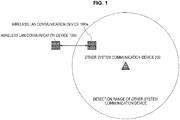
- FIG. 1 is a conceptual diagram for explaining the outline of the present disclosure.
- FIG. 1 illustrates a wireless LAN communication device 100a and a wireless LAN communication device 100b which belong to the wireless LAN system according to the present disclosure, and an other system communication device 200 which belongs to another system different from the wireless LAN system.
- the wireless LAN system is a wireless LAN system which complies with standards defined by IEEE 802.11, and supports multi-input multi-output (MIMO) which is one of technologies realizing higher speed of wireless communication.
- MIMO is a communication scheme in which each of a transmission device and a reception device includes a plurality of antennas, and which achieves higher speed by utilizing spatial multiplex.
- the transmission device in a MIMO communication system transmits transmission data while distributing the transmission data into the plurality of antennas, and the reception device in the MIMO communication system performs spatial separation on signals received at the plurality of antennas through signal processing.
- the wireless LAN communication device 100 is one of an access point device and a station device used in the wireless LAN system, the wireless LAN communication device 100 is not limited to these.
- the other system is an arbitrary system and is not particularly limited.
- the other system is a system (hereinafter, referred to as a "LAA system" for convenience) in which licensed assisted access using LTE (LAA) for which standardization is underway by 3rd generation partnership project (3GPP) which is a standards body regarding a third generation mobile phone, is used.
- LAA means a technology for enabling long term evolution (LTE) to be utilized in a frequency band for which a license is not required.
- Communication procedure in the LAA system is different from communication procedure in the wireless LAN system which complies with IEEE 802.11. Therefore, a communication device in the LAA system can only detect a signal transmitted from the wireless LAN system which complies with IEEE 802.11 by detecting received power.
- a frequency band for which a license is not required is also used in the wireless LAN system which complies with IEEE 802.11 in a similar manner to the LAA system, it can be considered that the wireless LAN system and the LAA system perform communication using the same frequency band. Therefore, there is a possibility that interference may occur by a signal of the wireless LAN system and a signal of the LAA system.
- FIG. 1 illustrates an example where the wireless LAN communication device 100a, the wireless LAN communication device 100b and the other system communication device 200 perform communication using the same frequency band, and the wireless LAN communication device 100a is located at a position where the wireless LAN communication device 100a can receive signals transmitted from the wireless LAN communication device 100b and the other system communication device 200. That is, there is a possibility that the signal transmitted from the wireless LAN communication device 100a or the signal to be received by the wireless LAN communication device 100a may interfere with the signal transmitted from the other system communication device 200.
- the present disclosure is a disclosure relating to a technology for reducing influence by such interference.
- the wireless LAN communication device 100b and the other system communication device 200 are in a so-called hidden node state. That is, the wireless LAN communication device 100b is in a state where the wireless LAN communication device 100b cannot detect a signal transmitted from the other system communication device 200, and the other system communication device 200 is in a state where the other system communication device 200 cannot detect a signal transmitted from the wireless LAN communication device 100b.
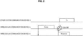
- FIG. 2 is a conceptual diagram for explaining the background of the present disclosure.
- FIG. 2 illustrates a wireless LAN communication device 1a, a wireless LAN communication device 1b and an other system communication device 2 as existing communication devices to distinguish from the communication device according to the present disclosure. Note that positional relationship among the respective communication devices is similar to positional relationship illustrated in FIG. 1 . That is, the wireless LAN communication device 1a is located at a position where the wireless LAN communication device 1a can receive signals transmitted from the wireless LAN communication device 1b and the other system communication device 2, and the wireless LAN communication device 1b and the other system communication device 2 are in a so-called hidden node state. Note that each block in FIG. 2 indicates a signal to be transmitted and received, an arrow indicates a transmission direction, and a horizontal axis indicates time (the same will also apply to the drawings which will be described later).
- the wireless LAN communication device 1a transmits a signal (for example, a data frame) for requesting a signal for response to the wireless LAN communication device 1b, and the wireless LAN communication device 1a which receives at least part of the signal transmits a signal for response (for example, an ACK frame).
- a signal for response for example, an ACK frame
- the other system communication device 2 cannot detect the signal for response transmitted from the wireless LAN communication device 1b. Therefore, there is a possibility that the other system communication device 2 determines that the other system communication device 2 can transmit a signal also in a period while the wireless LAN communication device 1b transmits the signal for response, and performs processing of transmitting a signal.
- the wireless LAN communication device 1a fails in reception processing (such as demodulation and decoding) of the signal for response.
- the wireless LAN communication device 1a cannot determine whether the signal transmitted from the wireless LAN communication device 1a is not received at the wireless LAN communication device 1b by influence of interference, or the like, or although the signal is received at the wireless LAN communication device 1b, the wireless LAN communication device 1a cannot receive the signal for response by influence of interference, or the like.
- the wireless LAN communication device 1a may erroneously determine that the signal is not received at the wireless LAN communication device 1b by influence of interference, or the like.
- the wireless LAN communication device 1a increases a contention window (CW) to be used for setting of a transmission waiting period of a signal to prevent occurrence of interference. Because the transmission waiting period until a signal is transmitted increases by the CW being increased, the communication performance of the wireless LAN system degrades. Further, there is a case where the wireless LAN communication device 1a lowers a transmission rate in transmission of a signal to reduce influence of interference. The communication performance of the wireless LAN system degrades also by the transmission rate being lowered.
- CW contention window
- the wireless LAN communication device 100 according to the present disclosure can determine whether or not a signal for response is transmitted using a method described below. That is, the wireless LAN communication device 100 according to the present disclosure can determine whether or not at least part of a signal transmitted by the wireless LAN communication device 100 is received at a transmission destination device.
- outline of functions of the present disclosure a functional configuration of the wireless LAN communication device 100, examples of the present disclosure (first example to fifth example), utilization examples of the present disclosure, and application examples of the present disclosure will be sequentially described.
- the wireless LAN communication device 100 transmits a predetermined signal (hereinafter, referred to as a "first signal” for convenience), and, even in the case of failure in reception processing of a signal for response to the signal (hereinafter, referred to as a "second signal” for convenience), can determine whether or not the signal for response is transmitted on the basis of information acquired in the process of the reception processing. That is, the wireless LAN communication device 100 can determine whether or not at least part of the predetermined signal transmitted by the wireless LAN communication device 100 is received at a transmission destination device.
- a predetermined signal hereinafter, referred to as a "first signal” for convenience
- the first example is an example where the wireless LAN communication device 100 performs determination on the basis of whether or not received power equal to or greater than a predetermined threshold is detected after a predetermined period has elapsed since a time point of transmission of a signal.
- the second example is an example where the wireless LAN communication device 100 performs determination on the basis of whether or not at least part of a signal pattern specific to a signal for response is detected.
- the third example is an example where the wireless LAN communication device 100 performs determination on the basis of information included in a physical layer header of the signal for response.
- the fourth example is an example where the wireless LAN communication device 100 performs determination on the basis of combination of a frequency band and a spatial stream used for reception processing of the signal for response.
- the fifth example is an example where, in the case where the wireless LAN communication device 100 performs reception processing of the signal for response using a plurality of frequency bands, the wireless LAN communication device 100 performs determination on the basis of whether or not reception processing is successful in part of the frequency bands.
- the wireless LAN communication device 100 may perform determination using the methods in the first example to the fifth example also in the case where the reception processing is successful, as well as in the case of failure in the reception processing of the signal for response. Further, while, a case is mainly assumed where the present disclosure is used in the case where interference occurs between the wireless LAN system and another system other than the wireless LAN system, the present disclosure may be used in the case where interference occurs between wireless LAN systems.
- FIG. 3 is a diagram illustrating the functional configuration of the wireless LAN communication device 100 according to the present disclosure.
- the wireless LAN communication device 100 includes a communication unit 110, a data processing unit 120 and a control unit 130.
- the communication unit 110 includes an amplifier unit 111, a wireless interface unit 112, a signal processing unit 113, a channel estimating unit 114 and a modulating and demodulating unit 115.
- the communication unit 110 functions as a transmitting unit, a receiving unit and a generating unit
- the data processing unit 120 functions as a generating unit
- the control unit 130 functions as a determining unit. Note that, as described above, because the wireless LAN communication device 100 according to the present disclosure supports MIMO, a plurality of amplifier units 111 and a plurality of wireless interface units 112 are provided.
- the amplifier unit 111 performs amplification processing of a signal. More specifically, upon signal reception, the amplifier unit 111 amplifies a received signal input from an antenna to predetermined power and outputs the amplified received signal to the wireless interface unit 112 which will be described later. Further, upon signal transmission, the amplifier unit 111 amplifies a transmission signal input from the wireless interface unit 112 to predetermined power and sends out the amplified transmission signal to the antenna. Note that these functions may be realized by the wireless interface unit 112.
- the wireless interface unit 112 Upon signal reception, the wireless interface unit 112 acquires a baseband signal by performing down-conversion on a received signal which is an analog signal provided from the amplifier unit 111, generates a received symbol stream by performing various kinds of processing such as filtering and conversion to a digital signal on the baseband signal and outputs the received symbol stream to the signal processing unit 113 which will be described later. Further, upon signal transmission, the wireless interface unit 112 converts input from the signal processing unit 113 into an analog signal, performs filtering and up-conversion to a carrier frequency band, and sends out the up-converted signal to the amplifier unit 111.
- the signal processing unit 113 Upon signal reception, the signal processing unit 113 acquires a data symbol stream independent for each received symbol stream by performing spatial processing on the received symbol stream provided from the wireless interface unit 112, and provides the data symbol stream to the modulating and demodulating unit 115 which will be described later. Further, upon signal transmission, the signal processing unit 113 performs spatial processing on the data symbol stream input from the modulating and demodulating unit 115 and provides the obtained one or more transmission symbol streams to the respective wireless interface units 112.
- the channel estimating unit 114 calculates complex channel gain information of a propagation channel from a preamble portion and a training signal portion among the received signals provided from the respective wireless interface units 112. The calculated complex channel gain information is utilized for demodulation processing at the modulating and demodulating unit 115 and spatial processing at the signal processing unit 113.
- the modulating and demodulating unit 115 Upon signal reception, acquires received data by performing demodulation, de-interleaving and decoding on the data symbol stream provided from the signal processing unit 113, and provides the received data to the data processing unit 120. Further, upon signal transmission, the modulating and demodulating unit 115 generates a data symbol stream by performing encoding, interleaving and modulation on the transmission data from the data processing unit 120 which will be described later on the basis of a coding and modulation scheme set by the control unit 130 which will be described later, and provides the stream to the signal processing unit 113.
- the data processing unit 120 Upon signal reception, the data processing unit 120 performs processing such as analysis of a MAC header for media access control (MAC), and error detection in a frame on the received data provided from the modulating and demodulating unit 115. Further, upon signal transmission, the data processing unit 120 generates a packet for transmission, generates transmission data by performing processing such as addition of a MAC header and addition of an error detection code on the packet, and provides the transmission data to the modulating and demodulating unit 115.
- processing such as analysis of a MAC header for media access control (MAC), and error detection in a frame on the received data provided from the modulating and demodulating unit 115.
- the data processing unit 120 Upon signal transmission, the data processing unit 120 generates a packet for transmission, generates transmission data by performing processing such as addition of a MAC header and addition of an error detection code on the packet, and provides the transmission data to the modulating and demodulating unit 115.
- processing such as analysis of a MAC header for media access control (MAC), and error
- the control unit 130 performs control of the above-described respective components. More specifically, the control unit 130 performs processing such as setting of a parameter to be used for processing of the above-described respective components, and scheduling of the processing. Further, in the present disclosure, in the case of failure in reception processing of the signal for response, the control unit 130 implements the processing described in the first example to the fifth example by controlling the respective components, performs determination as to whether or not the signal for response is transmitted, and implements processing in accordance with a determination result. Further, in the second example to the fourth example, the control unit 130 generates and transmits the signal for response so that the other wireless LAN communication device 100 which receives the signal for response can perform the above-described determination. Details will be described later.
- the first example of the present disclosure is an example where it is determined whether or not a second signal is transmitted on the basis of whether or not the wireless LAN communication device 100 detects power greater than a predetermined threshold after a predetermined period has elapsed since a time point of transmission of a first signal.
- the wireless LAN communication device 100a transmits a predetermined signal to the wireless LAN communication device 100b
- the wireless LAN communication device 100b transmits a signal for response to the wireless LAN communication device 100a after the wireless LAN communication device 100b normally receives at least part of the signal
- the wireless LAN communication device 100a fails in reception processing of the signal for response.
- transmission of the signal for response by the wireless LAN communication device 100b is performed after a first period since transmission of the predetermined signal by the wireless LAN communication device 100a has been completed.
- the wireless LAN communication device 100a determines that the wireless LAN communication device 100b normally receives at least part of the predetermined signal and transmits the signal for response on the basis that received power equal to or greater than a predetermined threshold can be detected after the first period has elapsed and before a second period has elapsed since the time point at which transmission of the predetermined signal was completed.
- the first period is, for example, short inter frame space (SIFS)
- the second period is, for example, an upper limit of a reception waiting period for the signal for response.
- the predetermined threshold is, for example, a threshold for detecting a preamble of the signal for response. Note that the first period, the second period and the predetermined threshold may be set while propagation delay and an individual difference of the wireless LAN communication devices 100 are taken into account or may be changed as appropriate.
- the wireless LAN communication device 100a can determine whether or not the signal for response is transmitted even if the wireless LAN communication device 100a fails in reception processing of the signal for response. That is, the wireless LAN communication device 100a can determine whether or not at least part of the predetermined signal transmitted by the wireless communication device 100a is normally received at the wireless LAN communication device 100b without confirming a reception state of the signal to the wireless LAN communication device 100b.
- FIG. 4 is a flowchart illustrating determination processing to be performed on the basis of detection of received power in the first example.
- step S1000 the wireless LAN communication device 100a transmits a predetermined signal to the wireless LAN communication device 100b. Then, the wireless LAN communication device 100b receives at least part of the signal and transmits a signal for response to the wireless LAN communication device 100a. Thereafter, in step S1004, the wireless LAN communication device 100a detects received power equal to or greater than the predetermined threshold (step S1004: Yes), and, in the case where a detection time point is after the first period has elapsed and before the second period has elapsed since a time point at which transmission of the predetermined signal was completed (step S1008: Yes), in step S1012, the wireless LAN communication device 100a determines that the signal for response is transmitted. That is, the wireless LAN communication device 100a determines that at least part of the predetermined signal transmitted by the wireless LAN communication device 100a is normally received by the wireless LAN communication device 100b.
- step S1020 the wireless LAN communication device 100a determines that the signal for response is not transmitted.
- step S1016 in the case where the second period has not elapsed (step S1016: No), the processing transitions to step S1004.
- the wireless LAN communication device 100 can determine that the received signal is not a signal transmitted from other systems, but a signal transmitted from the wireless LAN system by detecting these known signal patterns, it is possible to further improve detection accuracy of the signal for response.
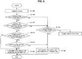
- FIG. 5 is a flowchart illustrating the determination processing to be performed on the basis of detection of received power and detection of the known signal pattern in the first example.
- step S1124 Operation from step S1100 to step S1108 and operation in step S1124 are the same as those in the example in FIG. 4 , description will be omitted.
- the wireless LAN communication device 100a utilizes the known signal pattern included in the signal for response for determination processing (step S1112: Yes), and in the case where all or part of the known signal pattern can be detected (step S1116: Yes), in step S1120, the wireless LAN communication device 100a determines that the signal for response is transmitted. That is, the wireless LAN communication device 100a determines that the predetermined signal transmitted by the wireless LAN communication device 100a is normally received by the wireless LAN communication device 100b.
- step S1120 the wireless LAN communication device 100a determines that the signal for response is transmitted. Further, in the case where all or part of the known signal pattern cannot be detected in step S1116 (step S1116: No), in step S1128, the wireless LAN communication device 100a determines that the signal for response is not transmitted.
- the second example of the present disclosure is an example where the wireless LAN communication device 100 performs determination on the basis of whether or not at least part of a signal pattern specific to the signal for response is detected.
- the signal pattern specific to the signal for response is a signal pattern of a PLCP preamble
- the signal pattern is not limited to this.
- the wireless LAN communication device 100 generates a signal for response using the PLCP preamble different from a PLCP preamble of a signal which is not a signal for response.
- the wireless LAN communication device 100 which receives the signal for response can determine whether or not the received signal is the signal for response on the basis of the PLCP preamble.
- FIG. 6 is a diagram for explaining determination processing to be performed on the basis of the signal pattern of the PLCP preamble in the second example.
- FIG. 6A illustrates an example of a signal pattern of an L-STF of a signal which is not the signal for response
- FIG. 6B illustrates an example of a signal pattern of an L-STF of the signal for response.
- the signal pattern in FIG. 6A and the signal pattern in FIG. 6B are different from each other in respective periods separated at predetermined intervals (described as s1, s2, s3 and s4 in the drawing).
- the wireless LAN communication device 100 can determine whether the received signal is the signal for response or a signal which is not the signal for response by calculating correlation of the received signal with the signal pattern of the signal for response and the signal pattern of a signal which is not the signal for response. Note that FIG. 6 is merely an example, and the present disclosure can be also applied to an L-LTF as well as the L-STF.
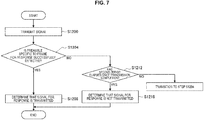
- FIG. 7 is a flowchart illustrating the determination processing to be performed on the basis of the signal pattern of the PLCP preamble in the second example.
- step S1200 the wireless LAN communication device 100a transmits a predetermined signal to the wireless LAN communication device 100b. Thereafter, the wireless LAN communication device 100b receives at least part of the signal and transmits a signal for response to the wireless LAN communication device 100a. Then, in the case where the wireless LAN communication device 100a detects all or part of the PLCP preamble of the signal for response (step S1204: Yes), in step S1208, the wireless LAN communication device 100a determines that the signal for response is transmitted. That is, the wireless LAN communication device 100a determines that at least part of the predetermined signal transmitted by the wireless LAN communication device 100a is normally received by the wireless LAN communication device 100b.
- step S1216 the wireless LAN communication device 100a determines that the signal for response is not transmitted.
- step S1212 in the case where the second period has not elapsed (step S1212: No), the processing transitions to step S1204.
- the PLCP preamble of the signal for response in the present example may be one obtained by changing part of a shape of the PLCP preamble of a signal which is not the signal for response.
- the PLCP preamble of the signal for response may be a signal pattern generated by shifting a phase of the PLCP preamble of the signal which is not the signal for response by a certain amount or may be a signal pattern generated by replacing part of the PLCP preamble of the signal which is not the signal for response with a predetermined signal pattern.
- all types of signals for response do not have to have the same PLCP preamble.
- different PLCP preambles may be used for each type (such as ACK and CTS) of the signal for response.
- the third example of the present disclosure is an example where the wireless LAN communication device 100 performs determination on the basis of information included in a physical layer header of the signal for response.
- a PLCP header will be described as an example of the physical layer header of the signal for response, the physical layer header is not limited to this.
- the wireless LAN communication device 100 sets a predetermined value at the PLCP header of the signal for response.
- the wireless LAN communication device 100 which receives the signal for response can determine whether or not the received signal is the signal for response by succeeding in reception processing of all or part of the PLCP header and confirming the presence of the predetermined value.
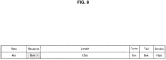
- FIG. 8 and FIG. 9 are diagrams illustrating an example of the PLCP header according to the third example.
- the PLCP header has a Rate field, a Reserved field, a Length field, a Parity bit, a Tail bit and a Service field.
- the wireless LAN communication device 100 which receives the signal determines whether or not the received signal is the signal for response on the basis of whether "0" is set or "1" is set in the Reserved field.
- FIG. 8 is merely an example, and a predetermined value indicating that the signal is the signal for response may be set in a field other than the Reserved field.
- a configuration itself of the PLCP header may be changed. More specifically, as illustrated in FIG. 9 , a Response field may be newly added to the PLCP header (in the drawing, a field corresponding to two bits is added), and a predetermined value indicating that the signal is the signal for response and indicating other information (such as a type of the signal) may be set in the field. Note that part of the existing field may be utilized instead of a new field being added. For example, the wireless LAN communication device 100 may reduce part of the Length field, and may set a predetermined value corresponding to a reduced data amount.
- the wireless LAN communication device 100 can determine whether or not the received signal is the signal for response.
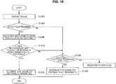
- FIG. 10 is a flowchart illustrating the determination processing to be performed on the basis of the information set in the PLCP header in the third example.
- step S1300 the wireless LAN communication device 100a transmits a predetermined signal to the wireless LAN communication device 100b. Then, the wireless LAN communication device 100b receives at least part of the signal and transmits a signal for response to the wireless LAN communication device 100a. Thereafter, in step S1304, the wireless LAN communication device 100a detects a PLCP preamble of the signal for response, and, in step S1308, performs reception processing such as demodulation and decoding on the signal for response.
- step S1316 the wireless LAN communication device 100a determines that the signal for response is transmitted. That is, the wireless LAN communication device 100a determines that at least part of the predetermined signal transmitted by the wireless LAN communication device 100a is normally received by the wireless LAN communication device 100b.
- step S1324 the wireless LAN communication device 100a determines that the signal for response is not transmitted. In the case where the second period has not elapsed in step S1320 (step S1320: No), the processing transitions to step S1304.
- the fourth example of the present disclosure is an example where the wireless LAN communication device 100 performs determination on the basis of combination of a frequency band and a spatial stream used for reception processing of the signal for response.
- the wireless LAN communication device 100 supporting MIMO can transmit a signal while designating a plurality of frequency bands and a plurality of spatial streams.
- resources expressed with a plurality of frequency bands and a plurality of spatial streams will be referred to as a "resource block".
- the wireless LAN communication device 100 according to the present example distinguishes between a resource block to be used for transmission of the signal for response and a resource block to be used for transmission of a signal which is not the signal for response.
- the wireless LAN communication device 100 which receives the signal determines whether or not the received signal is the signal for response on the basis of which resource block is used. More specifically, the wireless LAN communication device 100 determines whether or not the received signal is the signal for response on the basis of in which resource block the preamble is detected.
- the wireless LAN communication device 100 can determine whether or not the received signal is the signal for response on the basis of in which resource block the preamble is detected. Note that, even in the case where the wireless LAN communication device 100 cannot detect a preamble, the wireless LAN communication device 100 may determine whether or not the received signal is the signal for response on the basis of in which resource block received power of a predetermined threshold is detected.
- FIG. 11 is a diagram illustrating an example of the resource block in the fourth example.
- FIG. 11 illustrates an example in the case where a plurality of resource units (described as "RU: Resource Unit” in the drawing) is used on a frequency axis, and a plurality of spatial streams (described as "SS: Spatial Stream” in the drawing) is used.
- RU Resource Unit
- SS Spatial Stream
- resource blocks colored resource blocks in FIG. 11
- spatial streams which are different for each resource unit (frequency band) are applied are used for communication of the signal for response.
- FIG. 12 is a flowchart illustrating determination processing to be performed on the basis of the resource block to be used for communication in the fourth example.
- step S1400 the wireless LAN communication device 100a transmits a predetermined signal to the wireless LAN communication device 100b. Thereafter, the wireless LAN communication device 100b receives at least part of the signal and transmits a signal for response to the wireless LAN communication device 100a. Thereafter, in the case where the wireless LAN communication device 100a detects a preamble in a predetermined resource block to be used for communication of the signal for response in step S1404 (step S1404: Yes), in step S1408, the wireless LAN communication device 100a determines that the signal for response is transmitted. That is, the wireless LAN communication device 100a determines that at least part of the predetermined signal transmitted by the wireless LAN communication device 100a is normally received by the wireless LAN communication device 100b.
- step S1416 the wireless LAN communication device 100a determines that the signal for response is not transmitted.
- step S1412 in the case where the second period has not elapsed (step S1412: No), the processing transitions to step S1404.
- the fifth example of the present disclosure is an example where, in the case where the wireless LAN communication device 100 performs reception processing of the signal for response using a plurality of frequency bands, the wireless LAN communication device 100 performs determination on the basis of whether or not reception processing is successful in part of the frequency bands.
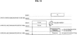
- FIG. 13 is a diagram for explaining a communication scheme according to the fifth example.
- the wireless LAN communication device 100a which is a transmission side transmits a predetermined signal using a plurality of frequency bands of a band 1 and a band 2, and the wireless LAN communication device 100b which is a reception side performs reception processing of the signal in the plurality of frequency bands.
- the wireless LAN communication device 100b then transmits a signal for response using the plurality of frequency bands of the band 1 and the band 2 in a similar manner as described above. It is assumed here that the other system communication device 200 uses the band 1 for transmission processing, and the wireless LAN communication device 100a fails in reception processing of the signal for response in the band 1 by a signal transmitted by the other system communication device 200 and the signal for response transmitted by the wireless LAN communication device 100b interfering with each other.
- the wireless LAN communication device 100a In the case where the present example is not applied, normally, in the case of failure in reception processing of a signal in part of frequency bands, even in the case where reception processing of the signal in other frequency bands is successful, the reception is not regarded as successful. Meanwhile, in the case where reception processing of the signal in part of frequency bands is successful, the wireless LAN communication device 100a according to the present example regards the reception as successful even in the case of failure in reception processing of the signal in other frequency bands.
- the wireless LAN communication device 100a regards the reception as successful on the basis of the success, and can determine that the wireless LAN communication device 100b on the reception side normally receives at least part of the predetermined signal and transmits the signal for response.
- FIG. 14 is a flowchart illustrating determination processing to be performed on the basis of a reception result in part of the frequency bands in the fifth example.
- step S1500 the wireless LAN communication device 100a transmits a predetermined signal to the wireless LAN communication device 100b. Then, the wireless LAN communication device 100b receives at least part of the signal and transmits a signal for response to the wireless LAN communication device 100a. Thereafter, in step S1504, the wireless LAN communication device 100a detects a PLCP preamble of the signal for response, and, in step S1508, performs reception processing such as demodulation and decoding on the signal for response.
- step S1516 the wireless LAN communication device 100a determines that the signal for response is transmitted even in the case of failure in reception processing in other frequency bands. That is, the wireless LAN communication device 100a determines that at least part of the predetermined signal transmitted by the wireless LAN communication device 100a is normally received by the wireless LAN communication device 100b.
- step S1524 the wireless LAN communication device 100a determines that the signal for response is not transmitted. In the case where the second period has not elapsed in step S1520 (step S1520: No), the processing transitions to step S1504.
- the fifth example of the present disclosure has been described above. Subsequently, utilization examples of the present disclosure will be described. As described above, according to the first example to the fifth example, even in the case of failure in reception processing of the signal for response, the wireless LAN communication device 100 can determine whether or not the received signal is the signal for response on the basis of information acquired in the process of the reception processing.
- utilization examples of the determination methods according to the first example to the fifth example in various communication schemes will be described.
- FIG. 15 is a diagram illustrating a case where the present disclosure is utilized for detection of the Block ACK frame. Note that the present disclosure may be utilized for detection of an ACK frame or a Multi STA Block ACK frame addressed to a plurality of communication devices instead of the Block ACK frame.
- the wireless LAN communication device 100a sets a transmission waiting period on the basis of a random number generated in a range from 0 to the CW to prevent occurrence of interference with signals transmitted from other communication devices, and transmits a data frame to the wireless LAN communication device 100b after the transmission waiting period has elapsed.
- This data frame may include a plurality of data units.
- the wireless LAN communication device 100b transmits a Block ACK frame to the wireless LAN communication device 100a as the signal for response. It is assumed that the wireless LAN communication device 100a fails in reception processing of the Block ACK frame as a result of a signal transmitted from other system communication device 200 and the Block ACK frame interfering with each other.
- the wireless LAN communication device 100a determines that the Block ACK frame is transmitted using a method of one of the above-described first example to the fifth example or a method of combination of the first example to the fifth example. That is, the wireless LAN communication device 100a determines that at least part of the data frame is normally received by the wireless LAN communication device 100b.
- the wireless LAN communication device 100a can appropriately perform subsequent communication. More specifically, the wireless LAN communication device 100a does not increase the CW to be used for setting of a waiting period for subsequent data transmission or keeping the CW at a minimum value (hereinafter, referred to as "CWmin" for convenience) by determining that at least part of the data frame is normally received by the wireless LAN communication device 100b. By this means, the wireless LAN communication device 100a can reduce a possibility that a waiting period for subsequent data transmission increases.
- CWmin a minimum value
- FIG. 16 is a flowchart illustrating the operation in the case where the present disclosure is utilized for detection of the Block ACK frame.
- step S1600 the wireless LAN communication device 100a transmits a data frame to the wireless LAN communication device 100b. Thereafter, the wireless LAN communication device 100b receives at least part of the data frame and transmits a Block ACK frame to the wireless LAN communication device 100a.
- step S1604 step S1604: No
- step S1608 the wireless LAN communication device 100a determines whether or not the Block ACK frame is transmitted using a method of one of the above-described first example to fifth example or a method of combination of the first example to the fifth example.
- step S1612 the wireless LAN communication device 100a sets a CW immediately before the Block ACK frame is transmitted or CWmin at the CW. Then, the wireless LAN communication device 100a retransmits the data frame after the transmission waiting period set on the basis of the CW has elapsed in step S1616, and processing is finished after the number of times of retransmission is counted in step S1620.
- step S1624 the wireless LAN communication device 100a increases the CW and performs retransmission of the data frame in step S1616 and subsequent steps. Note that, in the case where the wireless LAN communication device 100a succeeds in reception of the Block ACK frame without being influenced by interference, or the like, in step S1604 (step S1604: Yes), of course, the wireless LAN communication device 100a does not retransmit the data frame, and the processing is finished.
- the wireless LAN communication device 100a may control parameters other than the CW.
- the wireless LAN communication device 100a may maintain the transmission rate instead of lowering the transmission rate. That is, the wireless LAN communication device 100a can prevent the transmission rate from being inappropriately lowered by erroneous determination that the data frame is not normally received due to interference, or the like, so that it is possible to prevent reduction of communication speed.
- the wireless LAN communication device 100a may maintain the transmission power instead of increasing the transmission power. That is, the wireless LAN communication device 100a can prevent the transmission power from being inappropriately increased by erroneous determination that the data frame is not normally received due to interference, or the like, so that it is possible to prevent degradation of communication performance of the whole system due to increase of interference.
- the wireless LAN communication device 100a may maintain the threshold to be used for power detection instead of lowering the threshold. That is, the wireless LAN communication device 100a can prevent the threshold to be used for power detection from being inappropriately lowered by erroneous determination that the data frame is not normally received due to interference, or the like, so that it is possible to prevent detection of an unnecessary signal such as noise.
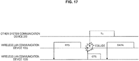
- FIG. 17 is a diagram illustrating a case where the present disclosure is utilized for detection of the CTS frame.
- a multi user RTS (MU RTS) frame addressed to a plurality of wireless LAN communication devices 100 may be used instead of the RTS frame.
- the wireless LAN communication device 100a transmits an RTS frame to the wireless LAN communication device 100b to confirm whether or not the wireless LAN communication device 100b which is a destination device is in a state where the wireless LAN communication device 100b can perform reception before transmitting a data frame.
- the wireless LAN communication device 100b which receives the RTS frame then transmits a CTS frame to the wireless LAN communication device 100a to make a notification that the wireless LAN communication device 100b is in a state where the wireless LAN communication device 100b can receive a data frame. It is assumed that the wireless LAN communication device 100a fails in reception processing of the CTS frame by a signal transmitted from the other system communication device 200 and the CTS frame interfering with each other.
- the wireless LAN communication device 100a determines that the CTS frame is transmitted using a method of one of the above-described first example to the fifth example or a method of combination of the first example to the fifth example. That is, the wireless LAN communication device 100a determines that RTS frame is normally received by the wireless LAN communication device 100b.
- the wireless LAN communication device 100a can appropriately perform the subsequent communication. For example, the wireless LAN communication device 100a transmits a data frame even while received power exceeding the predetermined threshold (that is, a signal transmitted from the other system communication device 200) is detected by determining that the RTS frame is received by the wireless LAN communication device 100b and the CTS frame is transmitted. More specifically, the wireless LAN communication device 100a may transmit a data frame even while received power exceeding the predetermined threshold is detected by judging that the other system communication device 200 and the wireless LAN communication device 100b are in a so-called hidden node state, and judging that influence of interference provided by the signal transmitted from the other system communication device 200 to the reception processing of the wireless LAN communication device 100b is not large. By this means, the wireless LAN communication device 100a can prevent the communication speed from being reduced by the RTS frame being retransmitted after the received power exceeding the predetermined threshold has been no longer detected.
- the predetermined threshold that is, a signal transmitted from the other system communication device 200
- FIG. 18 is a flowchart illustrating the operation in the case where the present disclosure is utilized for detection of the CTS frame.
- step S1700 the wireless LAN communication device 100a transmits an RTS frame to the wireless LAN communication device 100b. Thereafter, the wireless LAN communication device 100b receives the RTS frame and transmits a CTS frame to the wireless LAN communication device 100a.
- step S1704 step S1704: No
- step S1712 the wireless LAN communication device 100a determines whether or not the CTS frame is transmitted using a method of one of the above-described first example to fifth example or a method of combination of the first example to the fifth example.
- step S1712 In the case where it is determined that the CTS frame is transmitted (step S1712: Yes), in step S1716, the wireless LAN communication device 100a transmits a data frame even while received power exceeding the predetermined threshold is detected, and the processing is finished. In the case where it is determined that the CTS frame is not transmitted (step S1712: No), in step S1720, the wireless LAN communication device 100a retransmits the RTS after received power exceeding the predetermined threshold has been no longer detected, and the processing is finished.
- step S1704 step S1704: Yes
- step S1708 the wireless LAN communication device 100a transmits a data frame, and the processing is finished.
- FIG. 19 is a diagram illustrating a case where the present disclosure is utilized for detection of the Trigger-based PPDU.
- the wireless LAN communication device 100a transmits a trigger frame to the wireless LAN communication device 100b to request a Trigger-based PPDU.
- the wireless LAN communication device 100b which receives the trigger frame then transmits a Trigger-based PPDU on the basis of various kinds of parameters included in the trigger frame. It is assumed that the wireless LAN communication device 100a fails in reception processing of the Trigger-based PPDU in part of resource units or spatial streams by a signal transmitted from the other system communication device 200 and the Trigger-based PPDU interfering with each other.
- the wireless LAN communication device 100a determines that the Trigger-based PPDU is transmitted using a method of one of the above-described first example to the fifth example or a method of combination of the first example to the fifth example. That is, the wireless LAN communication device 100a determines that the trigger frame is normally received by the wireless LAN communication device 100b.
- the wireless LAN communication device 100a can appropriately perform subsequent communication. For example, the wireless LAN communication device 100a does not increase the CW or keeps the CW at CWmin upon retransmission of the trigger frame to receive the Trigger-based PPDU. By this means, the wireless LAN communication device 100a can reduce a possibility that the waiting period for subsequent transmission of the trigger frame increases. Further, the wireless LAN communication device 100a changes the resource unit or the spatial stream to be used for communication in conjunction with this. By this means, it is possible to reduce a possibility of occurrence of interference by a signal transmitted from the other system communication device 200 upon retransmission of the Trigger-based PPDU.
- FIG. 20 is a flowchart illustrating the operation in the case where the present disclosure is utilized for detection of the Trigger-based PPDU.
- step S1800 the wireless LAN communication device 100a transmits a trigger frame to the wireless LAN communication device 100b. Thereafter, the wireless LAN communication device 100b receives the trigger frame and transmits a Trigger-based PPDU to the wireless LAN communication device 100a.
- step S1804 step S1804: No
- step S1808 the wireless LAN communication device 100a determines whether or not the Trigger-based PPDU is transmitted using a method of one of the above-described first example to fifth example or a method of combination of the first example to the fifth example.
- step S1812 the wireless LAN communication device 100a sets a CW immediately before the Trigger-based PPDU is transmitted or CWmin at the CW. Further, in step S1816, the wireless LAN communication device 100a retransmits the trigger frame while changing the resource unit or the spatial stream to be used for subsequent communication.
- step S1808 determines to retransmit the trigger frame
- step S1820 Yes
- the wireless LAN communication device 100a increases the CW in step S1824 and retransmits the trigger frame without changing the resource unit or the spatial stream to be used for subsequent communication in step S1828.
- step S1820: No the processing is finished.
- step S1804 the wireless LAN communication device 100a does not retransmit the trigger frame, and the processing is finished.
- beamforming feedback such as, for example, beamforming feedback, which is transmitted in a form corresponding to a sounding frame (hereinafter, an "NDP-A frame” and “NDP” will be described as an example for convenience) or a feedback request (hereinafter, a "trigger frame” will be described as an example for convenience) in channel measurement procedure
- a feedback request hereinafter, a "trigger frame” will be described as an example for convenience
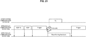
- FIG. 21 is a diagram illustrating a case where the present disclosure is utilized for detection of the beamforming feedback.
- the wireless LAN communication device 100a transmits a null data packet announcement (NDP-A) frame and a null data packet (NDP) to the wireless LAN communication device 100b to perform channel measurement.
- the wireless LAN communication device 100a then transmits a trigger frame to the wireless LAN communication device 100b to request beamforming feedback.
- the wireless LAN communication device 100b which receives the trigger frame transmits the beamforming feedback generated on the basis of the NDP to the wireless LAN communication device 100a. It is assumed that the wireless LAN communication device 100a fails in reception processing of the beamforming feedback by a signal transmitted from the other system communication device 200 and the beamforming feedback interfering with each other.
- the wireless LAN communication device 100a determines that the beamforming feedback is transmitted using a method of one of the above-described first example to the fifth example or a method of combination of the first example to the fifth example. That is, the wireless LAN communication device 100a determines that an NDP-A frame, an NDP, and the trigger frame are normally received by the wireless LAN communication device 100b.
- the wireless LAN communication device 100a can appropriately perform subsequent communication. For example, the wireless LAN communication device 100a retransmits only the trigger frame without retransmitting the NDP-A frame and the NDP by determining that the NDP-A frame, the NDP and the trigger frame are received by the wireless LAN communication device 100b and the beamforming feedback is transmitted. By this means, the wireless LAN communication device 100a can prevent channel measurement from being performed again by the NDP-A frame and the NDP being retransmitted. That is, the wireless LAN communication device 100a can improve communication efficiency by omitting unnecessary transmission processing of frames.
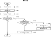
- FIG. 22 is a flowchart illustrating the operation in the case where the present disclosure is utilized for detection of the beamforming feedback.
- the wireless LAN communication device 100a transmits an NDP-A frame to the wireless LAN communication device 100b in step S1900, and transmits an NDP frame to the wireless LAN communication device 100b in step S1904. Then, in step S1908, the wireless LAN communication device 100a transmits a trigger frame for requesting beamforming feedback to the wireless LAN communication device 100b. Thereafter, the wireless LAN communication device 100b receives these signals and transmits beamforming feedback to the wireless LAN communication device 100a.
- step S1916 the wireless LAN communication device 100a determines whether or not the beamforming feedback is transmitted using a method of one of the above-described first example to fifth example or a method of combination of the first example to the fifth example.
- step S1920 the wireless LAN communication device 100a retransmits only the trigger frame without retransmitting the NDP-A frame and the NDP.
- step S1916 the wireless LAN communication device 100a requests the beamforming feedback again by retransmitting the NDP-A frame in step S1924, retransmitting the NDP in step S1928, and retransmitting the trigger frame in step S1920.
- the wireless LAN communication device 100 may be realized as mobile terminals such as smartphones, tablet personal computers (PCs), notebook PCs, portable game terminals, or digital cameras, fixed-type terminals such as television receivers, printers, digital scanners, or network storages, or car-mounted terminals such as car navigation devices.
- the wireless LAN communication device 100 may be realized as terminals that perform machine to machine (M2M) communication (also referred to as machine type communication (MTC) terminals) such as smart meters, vending machines, remotely controlled monitoring devices, or point of sale (POS) terminals.
- M2M machine to machine
- MTC machine type communication
- POS point of sale
- the wireless LAN communication device 100 may be wireless communication modules mounted in such terminals (for example, integrated circuit modules including one die).
- the wireless LAN communication device 100 may be realized as a wireless LAN access point (also referred to as a wireless base station) which has a router function or does not have a router function.
- the wireless LAN communication device 100 may be realized as a mobile wireless LAN router.
- the wireless LAN communication device 100 may also be a wireless communication module (for example, an integrated circuit module configured with one die) mounted on such devices.
- FIG. 23 is a block diagram illustrating an example of a schematic configuration of a smartphone 900 to which the technology of the present disclosure can be applied.
- the smartphone 900 includes a processor 901, a memory 902, a storage 903, an external connection interface 904, a camera 906, a sensor 907, a microphone 908, an input device 909, a display device 910, a speaker 911, a wireless communication interface 913, an antenna switch 914, an antenna 915, a bus 917, a battery 918, and an auxiliary controller 919.
- the processor 901 may be, for example, a central processing unit (CPU) or a system on chip (SoC), and controls functions of an application layer and other layers of the smartphone 900.
- the memory 902 includes random access memory (RAM) and read only memory (ROM), and stores data and programs executed by the processor 901.
- the storage 903 can include a storage medium such as a semiconductor memory or a hard disk.
- the external connection interface 904 is an interface for connecting an externally attachable device such as a memory card or a universal serial bus (USB) device to the smartphone 900.
- the camera 906 has an image sensor, for example, a charge coupled device (CCD) or a complementary metal oxide semiconductor (CMOS), to generate captured images.
- the sensor 907 can include a sensor group including, for example, a positioning sensor, a gyro sensor, a geomagnetic sensor, an acceleration sensor, and the like.
- the microphone 908 converts sounds input to the smartphone 900 into audio signals.
- the input device 909 includes, for example, a touch sensor that detects touches on a screen of the display device 910, a key pad, a keyboard, buttons, switches, and the like, to receive operation or information input from a user.
- the display device 910 has a screen such as a liquid crystal display (LCD), or an organic light emitting diode (OLED) display to display output images of the smartphone 900.
- the speaker 911 converts audio signals output from the smartphone 900 into sounds.
- the wireless communication interface 913 supports one or more wireless LAN standards of IEEE 802.11a, 11b, 11g, 11n, 11ac, 11ad and 11ax, to establish wireless communication.
- the wireless communication interface 913 can communicate with another device via a wireless LAN access point in an infrastructure mode.
- the wireless communication interface 913 can directly communicate with another device in a direct communication mode such as an ad hoc mode or Wi-Fi Direct (registered trademark). Note that, Wi-Fi Direct is different from the ad hoc mode.
- One of two terminals operates as an access point, and communication is performed directly between the terminals.
- the wireless communication interface 913 can typically include a baseband processor, a radio frequency (RF) circuit, a power amplifier, and the like.
- RF radio frequency
- the wireless communication interface 913 may be a one-chip module on which a memory that stores a communication control program, a processor that executes the program, and a relevant circuit are integrated.
- the wireless communication interface 913 may support another kind of wireless communication scheme such as a cellular communication scheme, a near-field communication scheme, or a proximity wireless communication scheme in addition to the wireless LAN scheme.
- the antenna switch 914 switches a connection destination of the antenna 915 among a plurality of circuits (for example, circuits for different wireless communication schemes) included in the wireless communication interface 913.
- the antenna 915 has a single or a plurality of antenna elements (for example, a plurality of antenna elements constituting a MIMO antenna), and is used for transmission and reception of wireless signals through the wireless communication interface 913.
- the smartphone 900 may include a plurality of antennas (for example, antennas for a wireless LAN or antennas for a proximity wireless communication scheme, or the like), without being limited to the example of FIG. 23 .
- the antenna switch 914 may be omitted from the configuration of the smartphone 900.
- the bus 917 connects the processor 901, the memory 902, the storage 903, the external connection interface 904, the camera 906, the sensor 907, the microphone 908, the input device 909, the display device 910, the speaker 911, the wireless communication interface 913, and the auxiliary controller 919 with each other.
- the battery 918 supplies electric power to each of the blocks of the smartphone 900 illustrated in FIG. 23 via power supply lines partially indicated by dashed lines in the drawing.
- the auxiliary controller 919 causes, for example, necessary minimum functions of the smartphone 900 to be operated in a sleep mode.
- the smartphone 900 may operate as a wireless access point (software AP) as the processor 901 executes the function of an access point at an application level.
- the wireless communication interface 913 may have the function of a wireless access point.
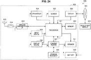
- FIG. 24 is a block diagram illustrating an example of a schematic configuration of a car navigation device 920 to which the technology of the present disclosure can be applied.
- the car navigation device 920 includes a processor 921, a memory 922, a Global Positioning System (GPS) module 924, a sensor 925, a data interface 926, a content player 927, a storage medium interface 928, an input device 929, a display device 930, a speaker 931, a wireless communication interface 933, an antenna switch 934, an antenna 935, and a battery 938.
- GPS Global Positioning System
- the processor 921 may be, for example, a CPU or an SoC controlling a navigation function and other functions of the car navigation device 920.
- the memory 922 includes RAM and ROM storing data and programs executed by the processor 921.
- the GPS module 924 measures a position of the car navigation device 920 (for example, latitude, longitude, and altitude) using GPS signals received from a GPS satellite.
- the sensor 925 can include a sensor group including, for example, a gyro sensor, a geomagnetic sensor, a barometric sensor, and the like.
- the data interface 926 is connected with an in-vehicle network 941 via, for example, a terminal (not illustrated) to acquire data generated on the vehicle side such as car speed data.
- the content player 927 reproduces content stored in a storage medium (for example, a CD or a DVD) inserted into the storage medium interface 928.
- the input device 929 includes, for example, a touch sensor that detects touches on a screen of the display device 930, buttons, switches, and the like to receive operation or information input from a user.
- the display device 930 has a screen such as an LCD or an OLED display to display images of the navigation function or reproduced content.
- the speaker 931 outputs sounds of the navigation function or reproduced content.
- the wireless communication interface 933 supports one or more wireless LAN standards of IEEE 802.11a, 11b, 11g, 11n, 11ac, 11ad, and the like to execute wireless communication.
- the wireless communication interface 933 can communicate with another device via a wireless LAN access point in the infrastructure mode.
- the wireless communication interface 933 can directly communicate with another device in a direct communication mode such as an ad hoc mode or Wi-Fi Direct.
- the wireless communication interface 933 can typically have a baseband processor, an RF circuit, a power amplifier, and the like.
- the wireless communication interface 933 may be a one-chip module on which a memory that stores a communication control program, a processor that executes the program, and a relevant circuit are integrated.
- the wireless communication interface 933 may support another kind of wireless communication scheme such as a near-field communication scheme, a proximity wireless communication scheme, or the cellular communication scheme in addition to the wireless LAN scheme.
- the antenna switch 934 switches a connection destination of the antenna 935 among a plurality of circuits included in the wireless communication interface 933.
- the antenna 935 has a single or a plurality of antenna elements and is used for transmission and reception of wireless signals from and to the wireless communication interface 933.
- the car navigation device 920 may include a plurality of antennas, without being limited to the example of FIG. 24 .
- the antenna switch 934 may be omitted from the configuration of the car navigation device 920.
- the battery 938 supplies electric power to each of the blocks of the car navigation device 920 illustrated in FIG. 24 via power supply lines partially indicated by dashed lines in the drawing. In addition, the battery 938 accumulates electric power supplied from the vehicle side.
- the wireless communication interface 933 may operate as the above-described wireless LAN communication device 100 and may provide wireless connection to a terminal carried by a user who gets in the vehicle.
- the technology of the present disclosure may be realized as an in-vehicle system (or a vehicle) 940 including one or more blocks of the above-described car navigation device 920, the in-vehicle network 941, and a vehicle-side module 942.
- the vehicle-side module 942 generates vehicle-side data such as a vehicle speed, the number of engine rotations, or failure information and outputs the generated data to the in-vehicle network 941.
- FIG. 25 is a block diagram illustrating an example of a schematic configuration of a wireless access point 950 to which the technology of the present disclosure can be applied.
- the wireless access point 950 includes a controller 951, a memory 952, an input device 954, a display device 955, a network interface 957, a wireless communication interface 963, an antenna switch 964, and an antenna 965.
- the controller 951 may be, for example, a CPU or a digital signal processor (DSP) and operates various functions (for example, access limitation, routing, encryption, a fire wall, and log management) of the Internet Protocol (IP) layer and higher layers of the wireless access point 950.
- the memory 952 includes RAM and ROM and stores a program executed by the controller 951 and various kinds of control data (for example, a terminal list, a routing table, an encryption key, security settings, and a log).
- the input device 954 includes, for example, a button or a switch, and receives operation performed by a user.
- the display device 955 includes an LED lamp and displays an operation status of the wireless access point 950.
- the network interface 957 is a wired communication interface that connects the wireless access point 950 with a wired communication network 958.
- the network interface 957 may include a plurality of connection terminals.
- the wired communication network 958 may be a LAN such as Ethernet (registered trademark) or may be a wide area network (WAN).
- the wireless communication interface 963 supports one or more wireless LAN standards of IEEE 802.11a, 11b, 11g, 11n, 11ac, 11ad, and 11ax and the like to supply wireless connection to a nearby terminal as an access point.
- the wireless communication interface 963 can typically include a baseband processor, an RF circuit, and a power amplifier.
- the wireless communication interface 963 may be a one-chip module in which memory storing a communication control program, a processor executing the program, and relevant circuits are integrated.
- the antenna switch 964 switches a connection destination of the antenna 965 among a plurality of circuits included in the wireless communication interface 963.
- the antenna 965 includes one antenna element or a plurality of antenna elements and is used to transmit and receive a wireless signal through the wireless communication interface 963.
- the wireless LAN communication device 100 transmits a predetermined signal (first signal), and, even in the case of failure in reception processing of a signal for response to the signal (second signal), can determine whether or not the signal for response is transmitted on the basis of information acquired in the process of the reception processing. That is, the wireless LAN communication device 100 can determine whether or not at least part of the predetermined signal transmitted by the wireless LAN communication device 100 is received at a transmission destination device. The wireless LAN communication device 100 can then appropriately perform subsequent communication on the basis of the determination.
- the respective steps illustrated in the above-described respective flowcharts do not necessarily have to be processed in chronological order along the order described as the flowcharts. That is, the respective steps may be processed in the order different from the order described as the flowcharts or may be processed in parallel.
- part of the components of the wireless LAN communication device 100 can be provided outside the wireless LAN communication device 100 as appropriate. Further, part of the functions of the wireless LAN communication device 100 may be embodied by the control unit 130.
- the control unit 130 may embody part of the functions of the communication unit 110 and the data processing unit 120.
- present technology may also be configured as below.
Landscapes
- Engineering & Computer Science (AREA)
- Computer Networks & Wireless Communication (AREA)
- Signal Processing (AREA)
- Computer Security & Cryptography (AREA)
- Mobile Radio Communication Systems (AREA)
Applications Claiming Priority (2)
| Application Number | Priority Date | Filing Date | Title |
|---|---|---|---|
| JP2016245494 | 2016-12-19 | ||
| PCT/JP2017/034716 WO2018116564A1 (ja) | 2016-12-19 | 2017-09-26 | 通信装置、通信制御方法およびプログラム |
Publications (2)
| Publication Number | Publication Date |
|---|---|
| EP3557798A1 true EP3557798A1 (de) | 2019-10-23 |
| EP3557798A4 EP3557798A4 (de) | 2020-01-01 |
Family
ID=62626278
Family Applications (1)
| Application Number | Title | Priority Date | Filing Date |
|---|---|---|---|
| EP17882974.3A Withdrawn EP3557798A4 (de) | 2016-12-19 | 2017-09-26 | Kommunikationsvorrichtung, kommunikationssteuerungsverfahren und programm |
Country Status (5)
| Country | Link |
|---|---|
| US (2) | US10980063B2 (de) |
| EP (1) | EP3557798A4 (de) |
| KR (1) | KR20190098136A (de) |
| CN (1) | CN110063035A (de) |
| WO (1) | WO2018116564A1 (de) |
Families Citing this family (2)
| Publication number | Priority date | Publication date | Assignee | Title |
|---|---|---|---|---|
| JP7107388B2 (ja) * | 2018-11-28 | 2022-07-27 | 日本電気株式会社 | 干渉検出システム、干渉検出装置、干渉検出方法、および干渉検出プログラム |
| WO2020179259A1 (ja) * | 2019-03-07 | 2020-09-10 | パナソニック インテレクチュアル プロパティ コーポレーション オブ アメリカ | 基地局、端末、送信方法及び受信方法 |
Family Cites Families (18)
| Publication number | Priority date | Publication date | Assignee | Title |
|---|---|---|---|---|
| JP4407126B2 (ja) * | 2003-01-09 | 2010-02-03 | ソニー株式会社 | 無線通信システム、無線通信装置及び無線通信方法、並びにコンピュータ・プログラム |
| US8085806B2 (en) | 2003-09-26 | 2011-12-27 | Agere Systems Inc. | Method and apparatus for detecting a collision in a carrier sense multiple access wireless system |
| KR101242952B1 (ko) * | 2005-05-13 | 2013-03-12 | 삼성전자주식회사 | 무선 근거리 네트워크에서 신호 송수신 방법 |
| US7656831B2 (en) | 2005-06-21 | 2010-02-02 | Ntt Docomo, Inc. | Method and apparatus for power saving in beacon generation of wireless networks in ad hoc mode |
| JP4740759B2 (ja) * | 2006-02-09 | 2011-08-03 | 三菱電機株式会社 | 無線通信システム |
| JP4506725B2 (ja) * | 2006-06-09 | 2010-07-21 | 株式会社デンソーウェーブ | タグリーダ |
| BRPI0717364B1 (pt) | 2006-10-31 | 2020-09-24 | Qualcomm Incorporated | Método e equipamento para aumentar os recursos ack para um sistema de comunicação sem fio |
| KR100953567B1 (ko) * | 2006-12-05 | 2010-04-21 | 한국전자통신연구원 | 이동통신 시스템에서의 수신확인신호 송수신 장치 및 방법 |
| CN104158637B (zh) * | 2008-06-30 | 2017-10-27 | 爱立信电话股份有限公司 | 电信系统中的方法和布置 |
| JP2010130118A (ja) * | 2008-11-25 | 2010-06-10 | Sony Corp | 送信装置、受信装置、通信システム、および、受信装置における処理方法 |
| CN102045144A (zh) * | 2011-01-17 | 2011-05-04 | 电信科学技术研究院 | 一种反馈ack/nack信息的方法及装置 |
| JP5889815B2 (ja) * | 2013-02-21 | 2016-03-22 | 日本電信電話株式会社 | 無線lan装置およびバックオフ制御方法 |
| EP3105987B1 (de) | 2014-02-13 | 2020-01-08 | Nokia Technologies Oy | Überlappende übertragung von rahmen in einem drahtlosen netzwerk bei einer signalstärke unter einer bestimmten schwelle |
| WO2015127658A1 (zh) * | 2014-02-28 | 2015-09-03 | 华为技术有限公司 | 数据传输方法和通信设备 |
| CN104092523B (zh) * | 2014-07-30 | 2017-07-28 | 东南大学 | 一种无线传感器网络多流竞争场景下的数据传输方法 |
| CN104393955B (zh) * | 2014-11-25 | 2018-04-27 | 北京北方烽火科技有限公司 | Ack/nack信号检测方法及装置 |
| JP6236617B2 (ja) | 2015-01-22 | 2017-11-29 | 日本電信電話株式会社 | 電波干渉防止機能を備えた通信装置及びその制御方法 |
| US20160262173A1 (en) * | 2015-03-03 | 2016-09-08 | Samsung Electronics Co., Ltd | Methods for uplink channel access in wireless local area networks |
-
2017
- 2017-09-26 EP EP17882974.3A patent/EP3557798A4/de not_active Withdrawn
- 2017-09-26 KR KR1020197016104A patent/KR20190098136A/ko not_active Ceased
- 2017-09-26 US US16/462,409 patent/US10980063B2/en not_active Expired - Fee Related
- 2017-09-26 CN CN201780076660.XA patent/CN110063035A/zh active Pending
- 2017-09-26 WO PCT/JP2017/034716 patent/WO2018116564A1/ja not_active Ceased
-
2021
- 2021-03-17 US US17/204,343 patent/US20210227584A1/en not_active Abandoned
Also Published As
| Publication number | Publication date |
|---|---|
| CN110063035A (zh) | 2019-07-26 |
| WO2018116564A1 (ja) | 2018-06-28 |
| EP3557798A4 (de) | 2020-01-01 |
| US20210227584A1 (en) | 2021-07-22 |
| KR20190098136A (ko) | 2019-08-21 |
| US10980063B2 (en) | 2021-04-13 |
| US20190306885A1 (en) | 2019-10-03 |
Similar Documents
| Publication | Publication Date | Title |
|---|---|---|
| US20220361031A1 (en) | Access point device, station device, wireless control method, communication control method, and program | |
| EP3534655A1 (de) | Kommunikationsvorrichtung, kommunikationssteuerungsverfahren und programm | |
| US12207295B2 (en) | Communication apparatus and communication method | |
| EP4152879A1 (de) | Kommunikationsvorrichtung, kommunikationsverfahren und programm | |
| US11083016B2 (en) | Wireless communication device | |
| US20210227584A1 (en) | Communication device, communication control method, and program | |
| US20210273741A1 (en) | Communication device and communication control method | |
| EP3528520A1 (de) | Kommunikationsvorrichtung, kommunikationssteuerungsverfahren und programm | |
| JP7632577B2 (ja) | 通信装置 | |
| CN111903172B (zh) | 无线通信设备和无线通信方法 | |
| JP7160049B2 (ja) | 通信装置、プログラム及び通信方法 | |
| EP3780895B1 (de) | Stationsvorrichtung, drahtlossteuerungsverfahren und programm |
Legal Events
| Date | Code | Title | Description |
|---|---|---|---|
| STAA | Information on the status of an ep patent application or granted ep patent |
Free format text: STATUS: THE INTERNATIONAL PUBLICATION HAS BEEN MADE |
|
| PUAI | Public reference made under article 153(3) epc to a published international application that has entered the european phase |
Free format text: ORIGINAL CODE: 0009012 |
|
| STAA | Information on the status of an ep patent application or granted ep patent |
Free format text: STATUS: REQUEST FOR EXAMINATION WAS MADE |
|
| 17P | Request for examination filed |
Effective date: 20190605 |
|
| AK | Designated contracting states |
Kind code of ref document: A1 Designated state(s): AL AT BE BG CH CY CZ DE DK EE ES FI FR GB GR HR HU IE IS IT LI LT LU LV MC MK MT NL NO PL PT RO RS SE SI SK SM TR |
|
| AX | Request for extension of the european patent |
Extension state: BA ME |
|
| A4 | Supplementary search report drawn up and despatched |
Effective date: 20191204 |
|
| RIC1 | Information provided on ipc code assigned before grant |
Ipc: H04W 28/04 20090101ALI20191128BHEP Ipc: H04W 74/08 20090101ALI20191128BHEP Ipc: H04L 1/18 20060101ALI20191128BHEP Ipc: H04L 1/16 20060101AFI20191128BHEP Ipc: H04W 84/12 20090101ALI20191128BHEP |
|
| DAV | Request for validation of the european patent (deleted) | ||
| DAX | Request for extension of the european patent (deleted) | ||
| STAA | Information on the status of an ep patent application or granted ep patent |
Free format text: STATUS: EXAMINATION IS IN PROGRESS |
|
| 17Q | First examination report despatched |
Effective date: 20210423 |
|
| RAP3 | Party data changed (applicant data changed or rights of an application transferred) |
Owner name: SONY GROUP CORPORATION |
|
| GRAP | Despatch of communication of intention to grant a patent |
Free format text: ORIGINAL CODE: EPIDOSNIGR1 |
|
| STAA | Information on the status of an ep patent application or granted ep patent |
Free format text: STATUS: GRANT OF PATENT IS INTENDED |
|
| INTG | Intention to grant announced |
Effective date: 20220708 |
|
| STAA | Information on the status of an ep patent application or granted ep patent |
Free format text: STATUS: THE APPLICATION IS DEEMED TO BE WITHDRAWN |
|
| 18D | Application deemed to be withdrawn |
Effective date: 20221119 |