EP3557038B1 - Anordnung eines funktionsbauteils zur beeinflussung einer tankentlüftung an einer ansaugleitung - Google Patents
Anordnung eines funktionsbauteils zur beeinflussung einer tankentlüftung an einer ansaugleitung Download PDFInfo
- Publication number
- EP3557038B1 EP3557038B1 EP19169870.3A EP19169870A EP3557038B1 EP 3557038 B1 EP3557038 B1 EP 3557038B1 EP 19169870 A EP19169870 A EP 19169870A EP 3557038 B1 EP3557038 B1 EP 3557038B1
- Authority
- EP
- European Patent Office
- Prior art keywords
- clip
- functional component
- intake line
- connection
- intake
- Prior art date
- Legal status (The legal status is an assumption and is not a legal conclusion. Google has not performed a legal analysis and makes no representation as to the accuracy of the status listed.)
- Active
Links
Images
Classifications
-
- F—MECHANICAL ENGINEERING; LIGHTING; HEATING; WEAPONS; BLASTING
- F02—COMBUSTION ENGINES; HOT-GAS OR COMBUSTION-PRODUCT ENGINE PLANTS
- F02M—SUPPLYING COMBUSTION ENGINES IN GENERAL WITH COMBUSTIBLE MIXTURES OR CONSTITUENTS THEREOF
- F02M25/00—Engine-pertinent apparatus for adding non-fuel substances or small quantities of secondary fuel to combustion-air, main fuel or fuel-air mixture
- F02M25/08—Engine-pertinent apparatus for adding non-fuel substances or small quantities of secondary fuel to combustion-air, main fuel or fuel-air mixture adding fuel vapours drawn from engine fuel reservoir
- F02M25/0836—Arrangement of valves controlling the admission of fuel vapour to an engine, e.g. valve being disposed between fuel tank or absorption canister and intake manifold
-
- F—MECHANICAL ENGINEERING; LIGHTING; HEATING; WEAPONS; BLASTING
- F02—COMBUSTION ENGINES; HOT-GAS OR COMBUSTION-PRODUCT ENGINE PLANTS
- F02M—SUPPLYING COMBUSTION ENGINES IN GENERAL WITH COMBUSTIBLE MIXTURES OR CONSTITUENTS THEREOF
- F02M25/00—Engine-pertinent apparatus for adding non-fuel substances or small quantities of secondary fuel to combustion-air, main fuel or fuel-air mixture
- F02M25/08—Engine-pertinent apparatus for adding non-fuel substances or small quantities of secondary fuel to combustion-air, main fuel or fuel-air mixture adding fuel vapours drawn from engine fuel reservoir
- F02M25/0872—Details of the fuel vapour pipes or conduits
-
- F—MECHANICAL ENGINEERING; LIGHTING; HEATING; WEAPONS; BLASTING
- F02—COMBUSTION ENGINES; HOT-GAS OR COMBUSTION-PRODUCT ENGINE PLANTS
- F02M—SUPPLYING COMBUSTION ENGINES IN GENERAL WITH COMBUSTIBLE MIXTURES OR CONSTITUENTS THEREOF
- F02M35/00—Combustion-air cleaners, air intakes, intake silencers, or induction systems specially adapted for, or arranged on, internal-combustion engines
- F02M35/10—Air intakes; Induction systems
- F02M35/10091—Air intakes; Induction systems characterised by details of intake ducts: shapes; connections; arrangements
- F02M35/10118—Air intakes; Induction systems characterised by details of intake ducts: shapes; connections; arrangements with variable cross-sections of intake ducts along their length; Venturis; Diffusers
-
- F—MECHANICAL ENGINEERING; LIGHTING; HEATING; WEAPONS; BLASTING
- F02—COMBUSTION ENGINES; HOT-GAS OR COMBUSTION-PRODUCT ENGINE PLANTS
- F02M—SUPPLYING COMBUSTION ENGINES IN GENERAL WITH COMBUSTIBLE MIXTURES OR CONSTITUENTS THEREOF
- F02M35/00—Combustion-air cleaners, air intakes, intake silencers, or induction systems specially adapted for, or arranged on, internal-combustion engines
- F02M35/10—Air intakes; Induction systems
- F02M35/10209—Fluid connections to the air intake system; their arrangement of pipes, valves or the like
- F02M35/10222—Exhaust gas recirculation [EGR]; Positive crankcase ventilation [PCV]; Additional air admission, lubricant or fuel vapour admission
-
- F—MECHANICAL ENGINEERING; LIGHTING; HEATING; WEAPONS; BLASTING
- F16—ENGINEERING ELEMENTS AND UNITS; GENERAL MEASURES FOR PRODUCING AND MAINTAINING EFFECTIVE FUNCTIONING OF MACHINES OR INSTALLATIONS; THERMAL INSULATION IN GENERAL
- F16L—PIPES; JOINTS OR FITTINGS FOR PIPES; SUPPORTS FOR PIPES, CABLES OR PROTECTIVE TUBING; MEANS FOR THERMAL INSULATION IN GENERAL
- F16L37/00—Couplings of the quick-acting type
- F16L37/08—Couplings of the quick-acting type in which the connection between abutting or axially overlapping ends is maintained by locking members
- F16L37/084—Couplings of the quick-acting type in which the connection between abutting or axially overlapping ends is maintained by locking members combined with automatic locking
- F16L37/0841—Couplings of the quick-acting type in which the connection between abutting or axially overlapping ends is maintained by locking members combined with automatic locking by means of a transversally slidable locking member surrounding the tube
-
- F—MECHANICAL ENGINEERING; LIGHTING; HEATING; WEAPONS; BLASTING
- F16—ENGINEERING ELEMENTS AND UNITS; GENERAL MEASURES FOR PRODUCING AND MAINTAINING EFFECTIVE FUNCTIONING OF MACHINES OR INSTALLATIONS; THERMAL INSULATION IN GENERAL
- F16B—DEVICES FOR FASTENING OR SECURING CONSTRUCTIONAL ELEMENTS OR MACHINE PARTS TOGETHER, e.g. NAILS, BOLTS, CIRCLIPS, CLAMPS, CLIPS OR WEDGES; JOINTS OR JOINTING
- F16B7/00—Connections of rods or tubes, e.g. of non-circular section, mutually, including resilient connections
- F16B7/22—Connections of rods or tubes, e.g. of non-circular section, mutually, including resilient connections using hooks or like elements
Definitions
- the invention relates to an arrangement of a functional component for influencing a tank ventilation on an intake line.
- a coupling device for lines carrying hydrocarbon liquids or vapors is known, whereby these lines can be tank ventilation lines.
- the coupling device is intended to create a connection between a tubular plug-in part and a sleeve-like coupling body.
- the coupling device is merely a connecting element that does not fulfill any further function, such as a venting function or a valve function.
- the coupling device comprises a coupling body with a nozzle receiving section and a locking element. The coupling device is thus designed in two parts and is intended to enable the simplest possible production from plastic using the injection molding process.
- the locking element has radially inwardly directed, elastically displaceable locking tabs which interact with a projection of a nozzle to be inserted and prevent the nozzle from becoming loose from the coupling device. In the assembled state, this results in a three-part arrangement consisting of the coupling body, locking element and nozzle.
- An ejector for insertion into a receiving body is known.
- the ejector is designed as a functional component in such a way that it can be inserted into a complementary receiving body in the correct position in order to fulfill its function as a jet pump in the arrangement.
- valve assembly for a line from a fuel evaporative emission control system to an intake manifold is known.
- the valve assembly comprises a housing provided on the intake manifold such that an outlet opening opens directly into the downstream line.
- a vent valve is known that is inserted into a holder of an intake line. The connection is made by means of a detachable clip.
- An ejector device with a suction chamber, a mixing channel, and a propulsion nozzle device for generating a propulsion medium jet directed along a jet direction out of the suction chamber and into the mixing channel which device has a fastening device with a base body.
- the fastening device comprises a translational locking device for preventing a translational movement of the base body relative to the suction channel in a direction parallel to the central axis of a connection piece of the suction channel. Projections and latching hooks on a mixing channel element of the base body are formed as locking elements of the locking device.
- valves and/or Venturi nozzles are used in practice. These valves can be used to adjust the amount of purge gas for tank ventilation or the amount of fuel vapors to be supplied to an intake line, and/or the duration of tank ventilation. It is known in practice to weld such functional components of the tank ventilation to an intake line.
- the invention is based on the object of providing an arrangement of a functional component on an intake manifold of an internal combustion engine that enables particularly simple and cost-effective installation on the intake manifold. This should also allow for the creation of a clip connection that is protected against unintentional or undesired loosening.
- the invention relates to arrangements with functional components in the form of tank vent valves and/or Venturi nozzles.
- the invention relates to an arrangement of a functional component for influencing a tank ventilation of a fuel tank functionally connected to an internal combustion engine on an intake line of the internal combustion engine.
- Corresponding means for establishing a clip connection are formed on the functional component and on the intake line of the internal combustion engine of an arrangement according to the invention, and the functional component is clipped directly to the intake line.
- the functional component is, in particular, a valve or a Venturi nozzle.
- Direct clipping means that no further connecting elements are arranged or interposed between the functional component and the intake line, for example, separately manufactured and separately assembled coupling elements.
- clipping the functional component to the intake line enables particularly simple assembly and cost-effective production of the intake line from a comparatively inexpensive plastic, whereas the functional component can be manufactured from any desired, higher-quality plastic.
- the intake line has at least one clip receptacle, which, in addition to an insertion opening for a corresponding clip, has a demolding opening extending transversely to the insertion direction, in particular a demolding opening extending perpendicular to the insertion direction.
- the demolding openings preferably all extend in the same direction, for example, all perpendicular to the insertion direction.
- a demolding opening is particularly required if an undercut formed in the clip receptacle with the blocking surface is to be easily demolded by means of plastic injection molding.
- the demolding opening - particularly when the clip is inserted and in the locked position - is completely closed by a cover structure arranged on the functional component in such a way that the clip, in the locked position, is no longer accessible via the demolding opening for release from the locked position.
- the cover structure preferably extends over the entire cross-sectional area of the demolding opening.
- Functional components provided for arrangements according to the invention for influencing a tank ventilation of a fuel tank functionally connected to an internal combustion engine, in particular a fuel tank of a motor vehicle, comprise in particular a A base body, wherein at least one flow channel for conducting fluid from an inlet side to an outlet side is formed in the base body.
- the functional component in particular the amount of fuel vapors from the fuel tank that are fed to the intake line, as well as the duration of tank venting phases, are controlled or regulated in terms of time and/or quantity.
- at least one means for establishing a clip connection between the functional component and an intake line is formed on the base body.
- At least one clip with at least one locking contour is formed on the base body, wherein at least one cover structure is formed integrally with the base body of the clip, and the cover structure is designed such that the cover structure protrudes transversely and longitudinally to the insertion direction relative to a clip head with the locking contour, and a release actuation of the clip in an inserted locking position is prevented.
- connection between the functional component is made in particular such that the inlet side or the outlet side of the base body is connected to the intake line in such a way that fluid can be introduced into the intake line through the flow channel.
- a sealing element for example a sealing ring
- the functional component is directly connected to an intake scoop as part of the intake line by means of the clip connection.
- the intake scoop forms in particular a part of the intake line of the internal combustion engine, on which damping elements and/or resonators are arranged, which serve to reduce flow and/or vibration noise of the intake line.
- the intake scoop is connected in particular upstream on an inflow side to a clean air pipe.
- the intake scoop is connected in particular downstream on an outflow side to a compressor of an exhaust gas turbocharger.
- a clip connection enables time-efficient, simple, and above all, tool-free installation of the functional component on the intake line. Another advantage is that no additional components are required to create the connection, such as screws, rivets, or other separate coupling elements.
- the clip connection also eliminates the comparatively expensive and time-consuming process of welding the functional component to the intake line. Welding has the further disadvantage that the components to be welded must usually be made of the same materials or at least materials that can be combined with one another for welding purposes. Since functional components are often made of high-quality and therefore rather expensive plastic, such as Polyacrylamide (PA), if welding is desired, the intake line must also be made of a rather expensive plastic. Implementing a suitable connection using a clip connection allows the intake line to be made of any plastic, and in particular, of a cheaper plastic than, for example, polypropylene (PP).
- PP polypropylene
- At least one cover structure is formed on the base body of a functional component with a clip or on the base body of a functional component with a clip receptacle in such a way that a releasing actuation of the clip in an inserted locking position is made inaccessible by the cover structure and is thus prevented.
- a cover structure is formed in particular in one piece with the base body of the clip or with the base body of the clip receptacle. If formed on the base body of the clip, the cover structure extends in particular over at least part of the length of the clip extending in the insertion direction.
- the base body is designed at least as part of a Venturi nozzle or to accommodate a Venturi nozzle.
- a Venturi nozzle has, in particular, a first flow channel with a first inlet side and an outlet side, and a second flow channel with a second inlet side.
- the second flow channel usually opens into the first flow channel, or vice versa.
- the first inlet side of the first flow channel is connected, in particular, to an intake line downstream of a compressor of a turbocharger, in particular to the so-called pressure pipe, and the outlet side is connected to the intake line upstream of the compressor.
- the second inlet side is fluidically connected to the fuel tank via a tank venting line.
- the base body is designed at least as part of a valve or to accommodate a valve.
- a valve can also be used to influence the tank ventilation of a fuel tank, in particular if the inlet side of the flow channel is fluidically connected to the fuel tank and the outlet side is fluidically connected to an intake line.
- the cross-section of the flow channel is narrowed or completely closed by the valve as needed, so that a control as needed and/or control of the tank venting is enabled.
- the valve is preferably provided with a pneumatic, hydraulic, and/or electrical connection, which serves to control the valve.
- an additional, externally driven pump can be provided to convey fluid through the flow channel.
- At least one clip with at least one locking contour is formed on the base body.
- two, three, four, or more such clips are formed.
- one or more clips are designed to interact with a corresponding clip receptacle in the intake line.
- the features of the at least one clip described below preferably, but not necessarily, apply to several clips, provided that two, three, four or more clips are provided.
- the at least one clip is preferably designed to be resilient and allows resilient compression and rebound due to its flexurally elastic design, in particular in a direction transverse to a connection direction or insertion direction.
- the connection direction or insertion direction is the direction in which the clip must be moved in order to be inserted into a corresponding clip receptacle and thus brought into its locking position.
- the at least one clip preferably has a clip body and a clip head with the locking contour.
- the clip body preferably has a width extending transversely to the longitudinal extent of the clip of 0.5 mm to 2 mm and preferably of 1 mm to 1.5 mm in order to provide suitable spring elasticity.
- a locking contour refers in particular to the formation of an abutment surface on a clip, which extends transversely to the connection direction or insertion direction, in particular perpendicular to the connection direction or insertion direction.
- an undercut with a blocking surface extending transversely to the insertion direction is formed in the corresponding clip receptacle. This blocking surface corresponds to the abutment surface and interacts in such a way that the clip is locked and a release of the clip connection is prevented.
- Such a clip with a locking contour represents a particularly simple and intuitive means for establishing the clip connection.
- a covering structure can in particular be plate-shaped, ie have a thickness which is much smaller than the length and the width, in particular less than 20 percent, less than 10 percent, or less than 5 percent of the smaller dimension of length or width.
- the cover structure is designed such that it protrudes transversely and longitudinally relative to a clip head with the locking contour in the direction of insertion.
- the clip connection is particularly secure, as the cover structure reliably prevents actuation of the clip in an inserted locking position and thus effectively prevents accidental and non-destructive release of the clip from the clip receptacle.
- the clip connection is preferably designed as a non-detachable connection, i.e., it is designed such that once the clip connection has been established, it cannot be released again without causing damage, even with the aid of tools.
- This design has the advantage that factory assembly by a vehicle manufacturer or automotive supplier with functional testing of the sealing function, particularly when mounted on a motor vehicle, can usually be designed for the lifetime of the motor vehicle, and deliberate or accidental release in a motor vehicle workshop can be reliably avoided. This prevents the possibility of minor leaks occurring due to a complete or partial loosening of a connection and/or improper reassembly of a loosened connection, which cannot be reliably detected by the diagnostic devices available in motor vehicles, in particular on-board diagnostics (OBD).
- OBD on-board diagnostics
- the cover structure ensures that the connection is not accidentally loosened or tampered with, and a partial or even minor loosening of the clip connection is reliably prevented.
- At least one clip receptacle for a corresponding clip arranged on the intake line can be formed on the base body.
- a clip receptacle is designed in particular in the form of a recess or opening in the base body, in particular such that a corresponding clip can be fully or partially inserted into the clip receptacle.
- the clip receptacle is designed in particular such that it has an undercut with a blocking surface, which interacts with a locking contour of the corresponding clip and thus prevents the clip from being pulled out of the clip receptacle.
- several clips and/or clip receptacles are formed on the base body, preferably at least two, three, four or more clips and/or clip receptacles.
- the clips or clip receptacles are preferably distributed over the circumference of the base body. arranged, particularly preferably distributed approximately evenly over the circumference.
- two, three, four or more clips and/or clip receptacles are provided on the functional component in order to fix the functional component in a predetermined position and secured against rotation relative to the intake line and to distribute the connecting forces acting on the clips across several clips.
- the clip receptacle on the base body is designed such that the clip connection between the functional component and the intake line is configured as a non-detachable connection, i.e. the connection in particular cannot be released non-destructively, preferably not even with the aid of standard tools or special tools.
- This is preferably achieved in that the locking contour is completely covered by the clip receptacle in an inserted locking position and cannot be reached by tools in such a way that the clip connection can be released again.
- an additional cover component is optionally provided which closes the demolding openings and completely covers the clip with the locking contour in the clip receptacle.
- the base body is formed in two parts.
- the base body has an upper part and a lower part, which are preferably connected to one another by welding, gluing, screwing and/or by means of a further clip connection.
- the parting plane between the upper part and the lower part of the base body is arranged in particular in the region of a clip receptacle formed on the base body. This makes it possible to avoid undercuts that are difficult to demold, particularly in the region of the clip receptacle, whereby the base body can be manufactured cost-effectively using the plastic injection molding process despite the undercuts that must be created.
- the tool parting plane for producing the upper part and/or lower part is preferably arranged in the region of the blocking surface of the clip holder, in particular such that the blocking surface runs in the direction of the tool parting plane and is itself part of the tool parting plane.
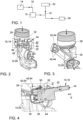
- Fig. 1 is a schematic view of an arrangement of a functional component 10, shown only schematically, on an intake line 12.
- the fuel tank 14 is shown schematically as a block, which is functionally connected to the functional component 10 via a tank vent line 16.
- the functional component 10 can be either a valve or a Venturi nozzle, as explained in more detail below.
- the functional component 10 is fluidically and thus flow-conductingly connected to the intake line 12.
- the intake line 12 extends here between an air filter 22 and a compressor 24 of an exhaust gas turbocharger (not shown).
- FIG. 2 to 4 A first embodiment of an arrangement with a first embodiment of a functional component 10 is shown.
- This functional component 10 is a valve 18, which is directly connected to an intake scoop 26.
- the intake scoop 26 forms part of the intake line 12.
- intake air flows through the intake line 12 in the direction of the arrows leading out of the intake line 12.
- the intake hood 26 is connected upstream to a clean air pipe 28. Downstream of the intake hood 26 is a Fig. 2 to 4 A compressor (not shown) of an exhaust gas turbocharger (also not shown) is connected to the intake scoop 26. In addition, several resonators (not shown) are provided on the intake scoop 26 under the cover 30. These resonators are optional elements that do not need to be present to implement the invention.
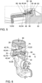
- the functional component 10, here in the form of the valve 18, has a base body 32.
- a flow channel in the Fig. 2 and 3 not visible and in the schematic sectional view of Fig. 4 not shown
- the inlet side 34 is in this case fluidically connected to the tank ventilation line 16 and a fuel tank 14 arranged upstream thereof.
- the outlet side 36 is directly connected to the intake scoop 26.
- a sealing ring 38 is arranged on the base body 32 of the functional component 10 in the region of the outlet side 36 such that the connection between the outlet side 36 and the intake scoop 26 is reliably and permanently sealed (cf. Fig. 4 ).
- an electrical connection 40 is provided on the base body 32, via which the valve 18 is controllable, whereby in particular it is possible to switch between an open position and a closed position.
- the connection between the intake scoop 26 and the valve 18 is realized in this case by means of a clip connection.
- both the intake scoop 26 and the valve 18 have means 42 for establishing the clip connection.
- the intake hood 26 has three clips 44 as such means 42.
- the intake hood 26 is cam-shaped in the area of the three clips 44 and the clips 44 are arranged approximately evenly distributed over the circumference of this cam-shaped area.
- Fig. 4 and 5 It can be clearly seen that the clips 44 comprise a clip body 46 and a clip head 48, wherein the clip head 48 has a locking contour 50 with an abutment surface 52.
- Clip receptacles 54 in the form of openings corresponding to the clips 44 are formed on the base body 32 of the valve 10 as means 42.
- the clip receptacles 54 each have an undercut 56 with a blocking surface 58.
- the clips 44 are inserted into the corresponding clip receptacles 54 in the insertion direction E through an insertion opening 60.
- the clips 44 are designed to be resilient and, in this case, spring transversely to the insertion direction E, initially radially inward with respect to the insertion axis and, after reaching the locking position in the area of the undercuts 56, radially outward again.
- the locking position is in the Fig. 4 and 5 clearly visible. Loosening of the clip connection is prevented by the interaction of the abutment surface 52 and the blocking surface 58.
- the base body 32 of the valve 18 is designed in such a way that the clips 44 in the Fig. 4 and 5 shown locking position cannot be pulled out of the respective clip receptacle 54 without causing damage.
- the clips 44 are surrounded in the locking position by the base body 32 of the functional component 10 in such a way that accessibility and thus actuation or release of the clips 44 is not possible either by hand or by means of a tool.
- the base body 32 of the valve 18 is formed in two parts, wherein the base body 32 comprises an upper part 62 and a lower part 64.
- the parting plane between the upper part 62 and the lower part 64 is in Fig. 4 visualized by the line marked with T.
- the demoulding of the lower part 64 takes place along the tool parting plane marked W, which is arranged at the height of the blocking surface 58.
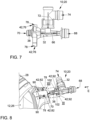
- FIG. 6 and 7 A second embodiment of an arrangement with a second embodiment of a functional component 10 is shown.
- the same reference numerals are used for identical or at least functionally equivalent components as for the description of the first embodiment.
- the functional component 10 shown is a Venturi nozzle 20.
- the Venturi nozzle 20 is clipped to an intake hood 26 by means of a clip connection.
- the intake hood 26 corresponds to the intake hood 26 of the Fig. 2 to 5 shown intake scoop 26.
- the valve 18 is connected to the intake scoop 26, in the embodiment shown in the Fig. 6 and 7
- the Venturi nozzle 20 is connected to the intake scoop 26.
- a first flow channel 66 with a first inlet side 68 and an outlet side 70 is provided in the base body 32 of the Venturi nozzle 20.
- the first inlet side 68 serves in this case for connection to a pressure pipe downstream of a compressor (not shown) of an exhaust gas turbocharger (also not shown).
- the outlet side 70 opens directly into the intake scoop 26.
- a second flow channel 72 is formed with a second inlet side 74, which can be connected to the tank ventilation line 16 leading to the fuel tank 14.
- the second flow channel 72 opens into the first flow channel 66.
- FIG. 6 and 7 At the positions where the valve 18 is made of the Fig. 2 to 5 Clips 44 are arranged, three clip receptacles 76 are formed on the base body 32 of the Venturi nozzle 20 (in Fig. 6 and 7 only two clip receptacles 76 are visible), which serve to hold the three clips 44 formed on the intake scoop 26.
- the clip receptacles 76 are functionally identical and have the same technical features as the clip receptacles 54 of the valve 18, which in Fig. 4 and 5 As can be seen from a summary of the Fig.
- the clip receptacles 76 are designed such that opposite an insertion opening 78 there is a demoulding opening 80 extending in the insertion direction E, whereby the Clips 44 remain accessible even in their locked position.
- a separate cover component (not shown) can be provided in addition to the base body 32, which covers the demolding openings 80 to prevent access to and actuation of the clips 44, in particular for the purpose of releasing the clip connection.
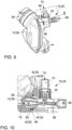
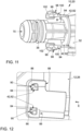
- FIG. 8 to 12 A third embodiment of an arrangement with a third embodiment of a functional component 10 is shown.
- the functional component 10 shown here is also a Venturi nozzle 20.
- the Venturi nozzle 20 is essentially identical to the one shown in the Fig. 6 and 7 shown Venturi nozzle 20 - particularly with respect to the first flow channel 66 and the second flow channel 72.
- the Venturi nozzles 20 from Fig. 6 and 7 as well as from the Fig. 8 to 12 therefore function the same.
- the following section discusses the essential differences of the third embodiment, which are primarily related to the clip connection.
- two clip receptacles 82 in the form of openings are formed as means 42 for establishing a clip connection on the intake scoop 26.
- the clip receptacles 82 each have, as shown in Fig. 12 As can be clearly seen, it has an undercut 84 with a blocking surface 86.
- a demolding opening 90 extending transversely, here perpendicularly, to the insertion direction E is formed.
- the two clips 92 corresponding to the clip receptacles 82 are shown.
- the clip bodies 94 of the clips 92 each have a width B of 1.25 mm extending transversely to the insertion direction E and are designed to be resilient transversely to the insertion direction E.
- the clips 92 have a clip head 96 with a locking contour 98 and with an abutment surface 100.
- a cover structure 102 is formed integrally with the respective clips 92.
- the cover structure 102 is in Fig. 8 in a top view and in Fig. 11 shown in a view from below.
- the cover structure 102 is arranged on the side of the clip head 96 which, in the locking position, faces the demolding opening 90.
- the cover structure 102 is plate-shaped and projects beyond the clip head 96 both in the insertion direction E and transversely thereto.
Landscapes
- Engineering & Computer Science (AREA)
- General Engineering & Computer Science (AREA)
- Mechanical Engineering (AREA)
- Chemical & Material Sciences (AREA)
- Combustion & Propulsion (AREA)
- Cooling, Air Intake And Gas Exhaust, And Fuel Tank Arrangements In Propulsion Units (AREA)
Description
- Die Erfindung betrifft eine Anordnung eines Funktionsbauteils zur Beeinflussung einer Tankentlüftung an einer Ansaugleitung.
- Aus
DE 10 2015 003 792 A1 ist eine Kupplungsvorrichtung für Kohlenwasserstoffflüssigkeiten bzw. -dämpfe führende Leitungen bekannt, wobei diese Leitungen Tankentlüftungsleitungen sein können. Die Kupplungsvorrichtung soll zur Herstellung einer Verbindung zwischen einem rohrförmigen Einsteckteil und einem muffenartigen Kupplungskörper dienen. Es handelt sich insoweit bei der Kupplungsvorrichtung lediglich um ein Verbindungselement, das darüber hinaus keine weitere Funktion erfüllt, wie z.B. eine Entlüftungsfunktion oder eine Ventilfunktion. Die Kupplungsvorrichtung umfasst einen Kupplungskörper mit einem Stutzenaufnahmeabschnitt und ein Verriegelungselement. Die Kupplungsvorrichtung ist damit zweiteilig gestaltet und soll so eine möglichst einfache Herstellung aus Kunststoff im Spritzgussverfahren ermöglichen. Das Verriegelungselement weist radial nach innen gerichtete, elastisch verlagerbare Verriegelungslaschen auf, welche mit einem Vorsprung eines einzuführenden Stutzens zusammenwirken und einem Lösen des Stutzens von der Kupplungsvorrichtung entgegenwirken. Damit ergibt sich im montierten Zustand eine dreiteilige Anordnung aus Kupplungskörper, Verriegelungselement und Stutzen. - Aus
DE 10 2016 005 468 A1 ist ein Ejektor zum Einschieben in einen Aufnahmekörper bekannt. Der Ejektor ist als Funktionsbauteil derart ausgestaltet, dass er in einen komplementär zu ihm ausgebildeten Aufnahmekörper lagerichtig einschiebbar ist, um seine Funktion als Strahlpumpe in der Anordnung zu erfüllen. - Aus
DE 44 41 879 A1 ist eine Ventilanordnung für eine Leitung von einem Kraftstoffverdunstungs-Rückhaltesystem zu einem Ansaugrohr bekannt. Die Ventilanordnung umfasst ein Gehäuse, das derart an dem Ansaugrohr vorgesehen ist, dass eine Auslassöffnung unmittelbar in die stromabwärtsseitige Leitung mündet. - Aus
WO 99/14478 A1 - Aus
DE 10 2016 206 616 A1 ist eine Ejektorvorrichtung mit einer Saugkammer, einem Mischkanal und einer Treibdüsenvorrichtung zum Erzeugen eines längs einer Strahlrichtung aus der Saugkammer heraus und in den Mischkanal hinein gerichteten Treibmediumstrahls bekannt, die eine Befestigungsvorrichtung mit einem Grundkörper aufweist. Die Befestigungsvorrichtung umfasst dabei in einer offenbarten Variante eine translative Arretiervorrichtung zur Vermeidung einer translativen Bewegung des Grundkörpers relativ zu dem Saugkanal in einer parallel zur Mittelachse eines Anschlussstutzens des Saugkanals verlaufenden Richtung. Als Arretierungselemente der Arretiervorrichtung sind Vorsprünge und Rasthaken an einem Mischkanalelement des Grundkörpers ausgebildet. - Zur Beeinflussung der Tankentlüftung eines funktional mit einer Brennkraftmaschine verbundenen Kraftstofftanks, insbesondere in Kraftfahrzeugen, werden in der Praxis Ventile und/oder Venturidüsen eingesetzt, über welche die Menge eines Spülgases für die Tankentlüftung bzw. die Menge an Kraftstoffdämpfen, welche einer Ansaugleitung zugeführt werden sollen, und/oder der Zeitraum der Durchführung der Tankentlüftung einstellbar ist. Aus der Praxis ist es bekannt, solche Funktionsbauteile der Tankentlüftung mit einer Ansaugleitung zu verschweißen.
- Der Erfindung liegt die Aufgabe zugrunde, eine Anordnung eines Funktionsbauteils an einer Ansaugleitung einer Brennkraftmaschine zur Verfügung zu stellen, welche eine besonders einfache und kostengünstige Montage an der Ansaugleitung ermöglicht. Dabei soll auch eine vor unbeabsichtigtem oder unerwünschtem Lösen gesicherte Clip-Verbindung hergestellt werden können. Insbesondere bezieht sich die Erfindung auf Anordnungen mit Funktionsbauteilen in Form von Tankentlüftungsventilen und/oder Venturidüsen.
- Die Lösung der Aufgabe erfolgt erfindungsgemäß mit den Merkmalen des Anspruchs 1. Weitere praktische Ausführungsformen und Vorteile der Erfindung sind in Verbindung mit verschiedenen Funktionsbauteilen beschrieben.
- Die Erfindung betrifft eine Anordnung eines Funktionsbauteils zur Beeinflussung einer Tankentlüftung eines funktional mit einer Brennkraftmaschine verbundenen Kraftstofftanks an einer Ansaugleitung der Brennkraftmaschine.
- An dem Funktionsbauteil und an der Ansaugleitung der Brennkraftmaschine einer erfindungsgemäßen Anordnung sind korrespondierende Mittel zur Herstellung einer Clip-Verbindung ausgebildet, und das Funktionsbauteil ist unmittelbar mit der Ansaugleitung verclipst. Bei dem Funktionsbauteil handelt es sich insbesondere um ein Ventil oder um eine Venturidüse. Mit einer unmittelbaren Verclipsung ist gemeint, dass zwischen dem Funktionsbauteil und der Ansaugleitung keine weiteren Verbindungselemente angeordnet oder zwischengeschaltet sind, beispielsweise separat hergestellte und separat zu montierende Kupplungselemente. Wie bereits vorstehend erläutert, ermöglicht ein Verclipsen des Funktionsbauteils mit der Ansaugleitung eine besonders einfache Montage und eine kostengünstige Herstellung der Ansaugleitung aus einem vergleichsweise günstigen Kunststoff, wohingegen das Funktionsbauteil aus einem beliebigen, hochwertigeren Kunststoff gefertigt werden kann.
- Erfindungsgemäß weist die Ansaugleitung mindestens eine Clip-Aufnahme auf, welche zusätzlich zu einer Einführöffnung für einen korrespondierenden Clip eine sich quer zur Einführrichtung erstreckende Entformungsöffnung aufweist, insbesondere eine sich senkrecht zur Einführrichtung erstreckende Entformungsöffnung. Wenn mehrere Clip-Aufnahmen vorgesehen sind, erstrecken sich die Entformungsöffnungen vorzugsweise alle in die gleiche Richtung, beispielsweise alle senkrecht zur Einführrichtung. Eine Entformungsöffnung wird insbesondere dann benötigt, wenn eine in der Clip-Aufnahme ausgebildete Hinterschneidung mit der Blockierfläche mittels Kunststoffspritzguss einfach entformbar sein soll.
- Um ein Lösen der Clip-Verbindung zwischen dem Funktionsbauteil und der Ansaugleitung über die Entformungsöffnungen zu verhindern, ist die Entformungsöffnung - insbesondere bei einem eingeführten, in Rastposition befindlichen Clip - vollständig von einer an dem Funktionsbauteil angeordneten Abdeckstruktur derart verschlossen, dass der Clip in der Rastposition über die Entformungsöffnung nicht mehr für ein Lösen aus der Rastposition zugänglich ist. Die Abdeckstruktur erstreckt sich dazu vorzugsweise über die gesamte Querschnittsfläche der Entformungsöffnung. So kann insbesondere eine vor unbeabsichtigtem oder unerwünschtem Lösen gesicherte Clip-Verbindung hergestellt werden, insbesondere eine Clip-Verbindung, die zerstörungsfrei nicht wieder lösbar ist, vorzugsweise auch nicht mit einem Standardwerkzeug oder einem Spezialwerkzeug.
- Für erfindungsgemäße Anordnungen vorgesehene Funktionsbauteile zur Beeinflussung einer Tankentlüftung eines funktional mit einer Brennkraftmaschine verbundenen Kraftstofftanks, insbesondere eines Kraftstofftanks eines Kraftfahrzeuges, umfassen insbesondere einen Grundkörper, wobei in dem Grundkörper mindestens ein Strömungskanal zum Führen von Fluid von einer Einlassseite zu einer Auslassseite ausgebildet ist. Mittels des Funktionsbauteils wird insbesondere die Menge an Kraftstoffdämpfen aus dem Kraftstofftank, welche der Ansaugleitung zugeführt werden, sowie die Dauer von Tankentlüftungsphasen zeitlich und/oder mengenmäßig gesteuert oder geregelt. An dem Grundkörper ist darüber hinaus mindestens ein Mittel zur Herstellung einer Clip-Verbindung des Funktionsbauteils mit einer Ansaugleitung ausgebildet. An dem Grundkörper ist zudem mindestens ein Clip mit mindestens einer Rastkontur ausgebildet, wobei einstückig mit dem Grundkörper des Clips mindestens eine Abdeckstruktur ausgebildet ist und die Abdeckstruktur derart gestaltet ist, dass die Abdeckstruktur gegenüber einem Clipkopf mit der Rastkontur quer und längs zur Einführrichtung hervorragt und eine lösende Betätigung des Clips in einer eingeführten Rastposition verhindert ist.
- Die Verbindung zwischen dem Funktionsbauteil erfolgt insbesondere derart, dass die Einlassseite oder die Auslassseite des Grundkörpers mit der Ansaugleitung so verbunden ist, dass Fluid durch den Strömungskanal in die Ansaugleitung eingeleitet werden kann. Zur Abdichtung zwischen dem Grundkörper und der Ansaugleitung ist insbesondere an der Ansaugleitung und/oder am Grundkörper ein Dichtungselement angeordnet, beispielsweise ein Dichtring. Vorzugsweise ist das Funktionsbauteil mit einer Ansaughutze als Teil der Ansaugleitung mittels der Clip-Verbindung unmittelbar verbunden. Die Ansaughutze bildet insbesondere einen Teil der Ansaugleitung der Brennkraftmaschine, an welcher Dämpfelemente und/oder Resonatoren angeordnet sind, die zur Reduzierung von Strömungs- und/oder Vibrationsgeräuschen der Ansaugleitung dienen. Die Ansaughutze ist insbesondere stromaufwärts an einer Einströmseite mit einem Reinluftrohr verbunden. Alternativ oder in Ergänzung dazu ist die Ansaughutze insbesondere stromabwärts an einer Ausströmseite mit einem Verdichter eines Abgasturboladers verbunden.
- Eine Clip-Verbindung ermöglicht eine zeiteffiziente, einfache und vor allem werkzeugfreie Montage des Funktionsbauteils an der Ansaugleitung. Vorteilhaft ist auch, dass keine weiteren Bauteile für die Herstellung einer Verbindung benötigt werden, wie beispielsweise Schrauben, Niete oder sonstige separate Kupplungselemente. Durch die Clip-Verbindung kann zudem ein vergleichsweise teures und aufwendiges Verschweißen des Funktionsbauteils mit der Ansaugleitung entfallen. Ein Verschweißen hat den weiteren Nachteil, dass die zu verschweißenden Bauteile üblicherweise aus den gleichen oder zumindest schweißtechnisch miteinander kombinierbaren Werkstoffen gebildet sein müssen. Da Funktionsbauteile in der Praxis häufig aus hochwertigem und somit eher teurem Kunststoff, wie beispielsweise Polyacrylamid (PA) hergestellt werden, folgt im Falle einer erwünschten Verschweißung daraus, dass auch die Ansaugleitung aus einem eher teuren Kunststoff hergestellt werden muss. Die Realisierung einer geeigneten Verbindung mittels Clip-Verbindung ermöglicht es, die Ansaugleitung aus einem beliebigen und insbesondere auch aus einem günstigeren Kunststoff herzustellen als beispielsweise aus Polypropylen (PP).
- In Verbindung mit einem Clip oder mehreren Clips ist es besonders vorteilhaft, dass an dem Grundkörper eines Funktionsbauteils mit Clip oder an dem Grundkörper eines Funktionsbauteils mit einer Clip-Aufnahme mindestens eine Abdeckstruktur derart ausgebildet ist, dass eine lösende Betätigung des Clips in einer eingeführten Rastposition durch die Abdeckstruktur unzugänglich gemacht ist und somit verhindert wird. Eine derartige Abdeckstruktur ist insbesondere einstückig mit dem Grundkörper des Clips oder mit dem Grundkörper der Clip-Aufnahme ausgebildet. Im Falle einer Ausbildung an dem Grundkörper des Clips erstreckt sich die Abdeckstruktur insbesondere mindestens über einen Teil der sich in Einführrichtung erstreckenden Länge des Clips.
- Besondere Vorteile der Erfindung ergeben sich, wenn der Grundkörper zumindest als Teil einer Venturidüse oder zur Aufnahme einer Venturidüse ausgebildet ist. Eine solche Venturidüse weist insbesondere einen ersten Strömungskanal mit einer ersten Einlassseite und einer Auslassseite sowie einen zweiten Strömungskanal mit einer zweiten Einlassseite auf. Dabei mündet der zweite Strömungskanal üblicherweise in den ersten Strömungskanal oder umgekehrt. Die erste Einlassseite des ersten Strömungskanals ist in einer erfindungsgemäßen Anordnung insbesondere mit einer Ansaugleitung stromabwärts eines Verdichters eines Turboladers verbunden, insbesondere mit dem sogenannten Druckrohr, und die Auslassseite ist mit der Ansaugleitung stromaufwärts des Verdichters verbunden. Die zweite Einlassseite ist in diesem Fall fluidal über eine Tankentlüftungsleitung mit dem Kraftstofftank verbunden. Durch die Steuerung und/oder Regelung des Massenstroms durch den ersten Strömungskanal wird - abhängig von dem jeweiligen Massenstrom - ein unterschiedlich großer Unterdruck in dem zweiten Strömungskanal erzeugt, wodurch die Entlüftung des Kraftstofftanks beeinflusst wird.
- Ebenfalls vorteilhaft ist es, wenn der Grundkörper zumindest als Teil eines Ventils oder zur Aufnahme eines Ventils ausgebildet ist. Ein solches Ventil kann ebenfalls zur Beeinflussung einer Tankentlüftung eines Kraftstofftanks dienen, insbesondere wenn die Einlassseite des Strömungskanals fluidal mit dem Kraftstofftank verbunden ist und die Auslassseite fluidal mit einer Ansaugleitung verbunden ist. Der Querschnitt des Strömungskanals wird durch das Ventil bedarfsweise verengt bzw. vollständig verschlossen, so dass eine bedarfsweise Steuerung und/oder Regelung der Tankentlüftung ermöglicht ist. Das Ventil ist dazu vorzugsweise mit einem pneumatischen, hydraulischen und/oder elektrischen Anschluss versehen, welcher zur Ansteuerung des Ventils dient. Alternativ oder in Ergänzung dazu kann zur Förderung von Fluid durch den Strömungskanal eine zusätzliche, extern angetriebene Pumpe vorgesehen sein.
- In einer praktischen Ausführungsform eines in einer erfindungsgemäßen Anordnung vorgesehenen Funktionsbauteils ist an dem Grundkörper mindestens ein Clip mit mindestens einer Rastkontur ausgebildet. Vorzugsweise sind zwei, drei, vier oder mehr solche Clips ausgebildet. Insbesondere ist ein Clip oder sind mehrere Clips dazu ausgelegt, mit einer korrespondierenden Clip-Aufnahme in der Ansaugleitung zusammenzuwirken.
- Die im Folgenden beschriebenen Merkmale des mindestens einen Clips gelten vorzugsweise, aber nicht zwingend für mehrere Clips, sofern zwei, drei, vier oder mehr Clips vorgesehen sind.
- Vorzugsweise ist der mindestens eine Clip federelastisch ausgebildet und erlaubt ein federelastisches Ein- und Ausfedern durch biegeelastische Gestaltung, insbesondere in einer Richtung quer zu einer Verbindungsrichtung bzw. Einführrichtung. Als Verbindungsrichtung bzw. Einführrichtung wird dabei diejenige Richtung bezeichnet, in welche der Clip bewegt werden muss, um in eine korrespondierende Clip-Aufnahme eingeführt und so in seine Rastposition gebracht zu werden. Der mindestens eine Clip weist vorzugsweise einen Clipkörper und einen Clipkopf mit der Rastkontur auf. Der Clipkörper weist vorzugsweise eine sich quer zur Längserstreckung des Clips erstreckende Breite von 0,5 mm bis 2 mm und vorzugsweise von 1 mm bis 1,5 mm auf, um eine geeignete Federelastizität bereitzustellen.
- Mit einer Rastkontur ist vorliegend insbesondere die Ausbildung einer Widerlagerfläche an einem Clip gemeint, welche sich quer zur Verbindungsrichtung bzw. Einführrichtung erstreckt, insbesondere senkrecht zur Verbindungsrichtung bzw. Einführrichtung. Vorzugsweise ist in der korrespondierenden Clip-Aufnahme eine Hinterschneidung mit einer sich quer zur Einführrichtung erstreckenden Blockierfläche ausgebildet, die mit der Widerlagerfläche korrespondiert und derart zusammenwirkt, dass der Clip verrastet und ein Lösen der Clip-Verbindung unterbunden ist. Ein derartiger Clip mit einer Rastkontur stellt ein besonders einfaches und intuitiv zu bedienendes Mittel zur Herstellung der Clip-Verbindung dar.
- Eine Abdeckstruktur kann insbesondere plattenförmig ausgebildet sein, d.h. eine Dicke aufweisen, die sehr viel kleiner ist als die Länge und die Breite, insbesondere weniger als 20 Prozent, weniger als 10 Prozent oder weniger als 5 Prozent der jeweils kleineren Dimension der Länge oder Breite.
- Insbesondere ist die Abdeckstruktur derart gestaltet, dass sie gegenüber einem Clipkopf mit der Rastkontur quer und längs zur Einführrichtung hervorragt. Wenn der Grundkörper selbst eine Abdeckstruktur aufweist, ist die Clip-Verbindung besonders sicher, da die Abdeckstruktur ein Betätigen des Clips in einer eingeführten Rastposition sicher verhindert und so ein versehentliches und zerstörungsfreies Lösen des Clips aus der Clip-Aufnahme wirksam verhindert wird. Die Clip-Verbindung ist vorzugsweise als nicht lösbare Verbindung ausgebildet, d.h. so gestaltet, dass sie nach einmaliger Herstellung der Clip-Verbindung auch mit Hilfe von Werkzeug zumindest nicht zerstörungsfrei wieder gelöst werden. Diese Gestaltung hat den Vorteil, dass eine werkseitige Montage bei einem Fahrzeughersteller oder Automobilzulieferer mit Funktionsüberprüfung der Dichtheitsfunktion, insbesondere im montierten Zustand an einem Kraftfahrzeug, üblicherweise für die Lebensdauer des Kraftfahrzeuges ausgelegt sein kann und ein bewusstes oder versehentliches Lösen in einer Kraftfahrzeugwerkstatt sicher vermieden werden kann. So kann ausgeschlossen werden, dass es durch ein vollständiges oder teilweises Lösen einer Verbindung und/oder durch nicht fachgerechte Wiedermontage einer gelösten Verbindung zu geringfügigen Leckagen kommt, die mittels in Kraftfahrzeugen zur Verfügung stehender Diagnosevorrichtungen, insbesondere einer sogenannten On-Board Diagnose (OBD), nicht zuverlässig detektiert werden können. Die Abdeckstruktur stellt in diesem Fall sicher, dass die Verbindung nicht ungewollt gelöst oder manipuliert wird, und ein teilweises bzw. nur geringfügiges Lösen der Clip-Verbindung wird sicher verhindert.
- Wie schon angedeutet, kann alternativ oder in Ergänzung zu einem Clip an dem Grundkörper mindestens eine Clip-Aufnahme für einen an der Ansaugleitung angeordneten, korrespondierenden Clip ausgebildet sein. Eine solche Clip-Aufnahme ist dabei insbesondere in Form einer Vertiefung oder Öffnung in dem Grundkörper ausgebildet, insbesondere derart, dass ein korrespondierender Clip vollständig oder teilweise in die Clip-Aufnahme einführbar ist. Die Clip-Aufnahme ist dabei insbesondere derart gestaltet, dass sie eine Hinterschneidung mit einer Blockierfläche aufweist, welche mit einer Rastkontur des korrespondierenden Clips zusammenwirkt und damit einem Herausziehen des Clips aus der Clip-Aufnahme entgegenwirkt.
- Insbesondere sind an dem Grundkörper mehrere Clips und/oder Clip-Aufnahmen ausgebildet, vorzugsweise mindestens zwei, drei, vier oder mehr Clips und/oder Clipaufnahmen. Die Clips oder Clipaufnahmen sind dabei vorzugsweise über den Umfang des Grundkörpers verteilt angeordnet, besonders bevorzugt in etwa gleichmäßig über den Umfang verteilt. Bevorzugt sind zwei, drei, vier oder mehr Clips und/oder Clip-Aufnahmen an dem Funktionsbauteil vorgesehen, um das Funktionsbauteil in einer vorgegebenen Lage und verdrehgesichert gegenüber der Ansaugleitung zu fixieren und die auf die Clips wirkenden Verbindungskräfte auf mehrere Clips zu verteilen.
- In einer besonders sicheren Ausführungsform ist die Clip-Aufnahme an dem Grundkörper derart ausgebildet, dass die Clip-Verbindung zwischen dem Funktionsbauteil und der Ansaugleitung als nicht lösbare Verbindung ausgelegt ist, d.h. die Verbindung insbesondere nicht zerstörungsfrei lösbar ist, vorzugsweise auch nicht mit Hilfe von Standardwerkzeug und auch nicht mit Hilfe von Spezialwerkzeug. Bevorzugt ist dies dadurch realisiert, dass die Rastkontur von der Clip-Aufnahme in einer eingeführten Rastposition vollständig verdeckt ist und auch nicht mittels Werkzeugen so zu erreichen ist, dass die Clip-Verbindung wieder gelöst werden kann. Da zum Teil Entformungsöffnungen zum Entformen der Hinterschneidung in der Clip-Aufnahme notwendig sind, ist gegebenenfalls ein zusätzliches Deckelbauelement vorgesehen, welches die Entformungsöffnungen verschließt und den Clip mit der Rastkontur in der Clip-Aufnahme vollständig verdeckt.
- In einer weiteren praktischen Ausführungsform eines in einer erfindungsgemäßen Anordnung vorgesehenen Funktionsbauteils ist der Grundkörper zweiteilig ausgebildet. Insbesondere weist der Grundkörper dabei ein Oberteil und ein Unterteil auf, welche vorzugsweise mittels Schweißen, Kleben, Schrauben und/oder mittels einer weiteren Clip-Verbindung miteinander verbunden sind. Die Trennebene zwischen dem Oberteil und dem Unterteil des Grundkörpers ist insbesondere im Bereich einer an dem Grundkörper ausgebildeten Clip-Aufnahme angeordnet. Dadurch können schwierig zu entformende Hinterschnitte, insbesondere im Bereich der Clip-Aufnahme, vermieden werden, wodurch trotz zu realisierender Hinterschneidungen eine kostengünstige Herstellung des Grundkörpers im Kunststoffspritzgießverfahren erfolgen kann.
- Die Werkzeugtrennebene zur Herstellung von Oberteil und/oder Unterteil ist dabei vorzugsweise im Bereich der Blockierfläche der Clip-Aufnahme angeordnet, insbesondere so, dass die Blockierfläche in Richtung der Werkzeugtrennebene verläuft und selbst Teil der Werkzeugtrennebene ist.
- Weitere praktische Ausführungsformen der Erfindung sind nachfolgend im Zusammenhang mit den Zeichnungen beschrieben. Es zeigen:
- Fig. 1
- eine schematische Übersicht einer Anordnung eines Funktionsbauteils an einer Ansaugleitung,
- Fig. 2
- eine Anordnung mit einem Funktionsbauteil in Form eines Ventils in einer ersten perspektivischen Ansicht,
- Fig. 3
- die Anordnung aus
Fig. 2 ohne das Ventil in einer anderen perspektivischen Ansicht, - Fig. 4
- den mit IV gekennzeichneten Bereich aus
Fig. 2 in einer vergrößerten Darstellung in einer schematischen Schnittdarstellung, - Fig. 5
- den mit V gekennzeichneten Bereich aus
Fig. 4 in einer vergrößerten Darstellung, - Fig. 6
- eine andere Anordnung mit einem Funktionsbauteil in Form einer Venturidüse in einer perspektivischen Ansicht,
- Fig. 7
- nur die Venturidüse aus
Fig. 6 in einer separaten Darstellung in einer Seitenansicht, - Fig. 8
- eine erfindungsgemäße Anordnung mit einem Funktionsbauteil in Form einer Venturidüse in einer perspektivischen Explosionsdarstellung,
- Fig. 9
- die Anordnung aus
Fig. 8 in einer perspektivischen Ansicht, - Fig. 10
- den mit X gekennzeichneten Bereich aus
Fig. 9 in einer Schnittdarstellung, - Fig. 11
- den mit XI gekennzeichneten Bereich der Venturidüse aus
Fig. 8 in einer vergrößerten Darstellung in einer Ansicht von unten und - Fig. 12
- den mit XII gekennzeichneten Bereich der Ansaugleitung in
Fig. 8 einer vergrößerten Darstellung. - In
Fig. 1 ist eine schematische Ansicht einer Anordnung eines nur schematisch dargestellten Funktionsbauteils 10 an einer Ansaugleitung 12 dargestellt. Ganz links inFig. 1 ist ein schematisch als Block dargestellter Kraftstofftank 14 dargestellt, welcher über eine Tankentlüftungsleitung 16 mit dem Funktionsbauteil 10 funktional verbunden ist. Bei dem Funktionsbauteil 10 kann es sich entweder um ein Ventil oder um eine Venturidüse handeln, wie im Folgenden noch näher erläutert wird. Das Funktionsbauteil 10 ist fluidal und somit strömungsleitend mit der Ansaugleitung 12 verbunden. Die Ansaugleitung 12 erstreckt sich hier zwischen einem Luftfilter 22 und einem Verdichter 24 eines nicht dargestellten Abgasturboladers. - In Verbindung mit den nachfolgenden
Fig. 2 bis 10 werden im Folgenden drei verschiedene Ausführungsformen von Anordnungen und Funktionsbauteilen 10 an einer Ansaugleitung 12 erläutert. - In den
Fig. 2 bis 4 ist eine erste Ausführungsform einer Anordnung mit einer ersten Ausführungsform eines Funktionsbauteils 10 dargestellt. Bei diesem Funktionsbauteil 10 handelt es sich um ein Ventil 18, welches unmittelbar mit einer Ansaughutze 26 verbunden ist. Dabei bildet die Ansaughutze 26 einen Teil der Ansaugleitung 12. Beim Betrieb einer nicht dargestellten Brennkraftmaschine strömt Ansaugluft durch die Ansaugleitung 12 in Richtung der aus der Ansaugleitung 12 herausführenden Pfeile. - Die Ansaughutze 26 ist stromaufwärts mit einem Reinluftrohr 28 verbunden. Stromabwärts schließt sich an die Ansaughutze 26 ein in den
Fig. 2 bis 4 nicht dargestellter Verdichter eines ebenfalls nicht dargestellten Abgasturboladers an. Zudem sind an der Ansaughutze 26 unter der Abdeckung 30 mehrere, nicht dargestellte Resonatoren vorgesehen, welche zur Dämpfung von Schwingungen eingesetzt werden. Bei diesen Resonatoren handelt es sich um optionale Elemente, die für die Realisierung der Erfindung nicht vorhanden sein müssen. - Das Funktionsbauteil 10, hier in Form des Ventils 18, weist einen Grundkörper 32 auf. In dem Grundkörper 32 ist ein Strömungskanal (in den
Fig. 2 und 3 nicht sichtbar und in der schematischen Schnittdarstellung vonFig. 4 nicht dargestellt) ausgebildet, welcher von einer Einlassseite 34 zu einer Auslassseite 36 führt. Die Einlassseite 34 ist vorliegend mit der Tankentlüftungsleitung 16 und einem stromaufwärts davon angeordneten Kraftstofftank 14 strömungsleitend verbunden. Die Auslassseite 36 ist unmittelbar mit der Ansaughutze 26 verbunden. An dem Grundkörper 32 des Funktionsbauteils 10 ist im Bereich der Auslassseite 36 ein Dichtring 38 so angeordnet, dass die Verbindung zwischen Auslassseite 36 und der Ansaughutze 26 zuverlässig und dauerhaft abgedichtet ist (vgl.Fig. 4 ). Ferner ist an dem Grundkörper 32 ein elektrischer Anschluss 40 vorgesehen, über welchen das Ventil 18 steuerbar ist, wobei insbesondere zwischen einer Öffnungsstellung und einer Schließstellung geschaltet werden kann. Es ist optional auch möglich, dass mehrere Öffnungsstellungen mit verschieden großen Durchströmquerschnitten vorgesehen sind. - Die Verbindung zwischen der Ansaughutze 26 und dem Ventil 18 ist vorliegend mittels einer Clip-Verbindung realisiert. Dazu weisen sowohl die Ansaughutze 26 als auch das Ventil 18 Mittel 42 zur Herstellung der Clip-Verbindung auf. Wie in
Fig. 3 zu sehen ist, weist die Ansaughutze 26 vorliegend als solche Mittel 42 drei Clips 44 auf. Die Ansaughutze 26 ist im Bereich der drei Clips 44 nockenförmig gestaltet und die Clips 44 sind über den Umfang dieses nockenförmigen Bereichs ungefähr gleichmäßig verteilt angeordnet. InFig. 4 und5 ist gut zu erkennen, dass die Clips 44 einen Clipkörper 46 und einen Clipkopf 48 umfassen, wobei der Clipkopf 48 eine Rastkontur 50 mit einer Widerlagerfläche 52 aufweist. An dem Grundkörper 32 des Ventils 10 sind als Mittel 42 zu den Clips 44 korrespondierende Clip-Aufnahmen 54 in Form von Öffnungen ausgebildet. Die Clip-Aufnahmen 54 weisen jeweils eine Hinterschneidung 56 mit einer Blockierfläche 58 auf. - Zur Herstellung der Clip-Verbindung werden die Clips 44 in die korrespondierenden Clip-Aufnahmen 54 in Einführrichtung E durch eine Einführöffnung 60 eingeführt. Die Clips 44 sind federelastisch ausgebildet und federn vorliegend quer zur Einführrichtung E zunächst - in Bezug auf die Einführachse - radial nach innen und nach Erreichen der Rastposition im Bereich der Hinterschneidungen 56 wieder radial nach außen. Die Rastposition ist in den
Fig. 4 und5 gut erkennbar. Ein Lösen der Clip-Verbindung wird durch das Zusammenwirken der Widerlagerfläche 52 und der Blockierfläche 58 verhindert. - Vorliegend ist der Grundkörper 32 des Ventils 18 derart gestaltet, dass die Clips 44 in der in
Fig. 4 und5 gezeigten Rastposition nicht zerstörungsfrei aus der jeweiligen Clip-Aufnahme 54 herausziehbar sind. Die Clips 44 werden dazu in der Rastposition von dem Grundkörper 32 des Funktionsbauteils 10 derart umgeben, dass eine Zugänglichkeit und somit eine Betätigung bzw. ein Lösen der Clips 44 weder von Hand noch mittels eines Werkzeuges möglich ist. - Um die Hinterschneidungen 56 herstellungstechnisch vorteilhaft in einem Kunststoffspritzgießteil realisieren zu können, ist der Grundkörper 32 des Ventils 18 zweiteilig ausgebildet, wobei der Grundkörper 32 ein Oberteil 62 und ein Unterteil 64 umfasst. Die Trennebene zwischen dem Oberteil 62 und dem Unterteil 64 ist in
Fig. 4 durch die mit T gekennzeichnete Linie visualisiert. Die Entformung des Unterteils 64 erfolgt vorliegend entlang der mit W gekennzeichneten Werkzeugtrennebene, welche auf der Höhe der Blockierfläche 58 angeordnet ist. - In Verbindung mit den
Fig. 6 und7 ist eine zweite Ausführungsform einer Anordnung mit einer zweiten Ausführungsform eines Funktionsbauteils 10 dargestellt. Im Folgenden werden zur Erläuterung dieser zweiten Ausführungsform und einer dritten Ausführungsform für identische oder zumindest funktionsgleiche Bauelemente dieselben Bezugszeichen verwendet, wie zur Beschreibung der ersten Ausführungsform. - Bei dem in
Fig. 6 und7 gezeigten Funktionsbauteil 10 handelt es sich um eine Venturidüse 20. Die Venturidüse 20 ist vorliegend mittels einer Clip-Verbindung mit einer Ansaughutze 26 verclipst. Die Ansaughutze 26 entspricht der Ansaughutze 26 der in denFig. 2 bis 5 gezeigten Ansaughutze 26. An der Position (Schnittstelle), bei der in denFig. 2 bis 5 gezeigten Ausführungsform das Ventil 18 mit der Ansaughutze 26 verbunden ist, ist bei der in denFig. 6 und7 gezeigten Ausführungsform die Venturidüse 20 mit der Ansaughutze 26 verbunden. - In dem Grundkörper 32 der Venturidüse 20 ist ein erster Strömungskanal 66 mit einer ersten Einlassseite 68 und einer Auslassseite 70 vorgesehen. Die erste Einlassseite 68 dient vorliegend zur Verbindung mit einem Druckrohr stromabwärts eines nicht dargestellten Verdichters eines ebenfalls nicht dargestellten Abgasturboladers. Die Auslassseite 70 mündet unmittelbar in die Ansaughutze 26. Zudem ist ein zweiter Strömungskanal 72 mit einer zweiten Einlassseite 74 ausgebildet, welche mit der Tankentlüftungsleitung 16, welche zu dem Kraftstofftank 14 führt, verbindbar ist. Der zweite Strömungskanal 72 mündet in den ersten Strömungskanal 66. Durch eine Veränderung des Massenstroms durch den ersten Strömungskanal 66, der steuerbar und/oder regelbar ist, kann der Unterdruck in dem zweiten Strömungskanal 72 verändert werden, wodurch die Tankentlüftung des Kraftstofftanks 14 gesteuert und/oder geregelt werden kann.
- An den Positionen, wo bei dem Ventil 18 aus den
Fig. 2 bis 5 Clips 44 angeordnet sind, sind an dem Grundkörper 32 der Venturidüse 20 drei Clip-Aufnahmen 76 ausgebildet (inFig. 6 und7 sind nur zwei Clip-Aufnahmen 76 sichtbar), die zur Aufnahme der drei an der Ansaughutze 26 ausgebildeten Clips 44 dienen. Die Clip-Aufnahmen 76 sind funktionsgleich und mit den gleichen technischen Merkmalen realisiert wie die Clip-Aufnahmen 54 des Ventils 18, das inFig. 4 und5 dargestellt ist. Wie aus einer Zusammenschau derFig. 6 und7 deutlich wird, , sind die Clip-Aufnahmen 76 so ausgebildet, dass gegenüberliegend einer Einführöffnung 78 eine sich in Einführrichtung E erstreckende Entformungsöffnung 80 ausgebildet ist, wodurch die Clips 44 auch in ihrer Rastposition noch zugänglich bleiben. Um einem Lösen der Clip-Verbindung entgegenzuwirken, kann zusätzlich zu dem Grundkörper 32 ein separates Deckelbauelement (nicht dargestellt) vorgesehen sein, welches die Entformungsöffnungen 80 verdeckt, um ein Zugänglichmachen und Betätigen der Clips 44, insbesondere zum Zwecke eines Lösens der Clip-Verbindung, zu vermeiden. - In den
Fig. 8 bis 12 ist eine dritte Ausführungsform einer Anordnung mit einer dritten Ausführungsform eines Funktionsbauteils 10 dargestellt. Bei dem hier gezeigten Funktionsbauteil 10 handelt es sich ebenfalls um eine Venturidüse 20. - Die Venturidüse 20 ist im Wesentlichen identisch zu der in den
Fig. 6 und7 gezeigten Venturidüse 20 aufgebaut - insbesondere in Bezug auf den ersten Strömungskanal 66 und den zweiten Strömungskanal 72.Die Venturidüsen 20 ausFig. 6 und7 sowie aus denFig. 8 bis 12 funktionieren daher gleich. Im Folgenden wird auf die wesentlichen Unterschiede der dritten Ausführungsform eingegangen, welche vor allem in Zusammenhang mit der Clip-Verbindung realisiert sind. - Vorliegend sind als Mittel 42 zur Herstellung einer Clip-Verbindung an der Ansaughutze 26 zwei Clip-Aufnahmen 82 in Form von Öffnungen ausgebildet. Die Clip-Aufnahmen 82 weisen jeweils, wie in
Fig. 12 gut zu erkennen ist, eine Hinterschneidung 84 mit einer Blockierfläche 86 auf. Zur Entformung dieser Hinterschneidungen 84 mit der Blockierfläche 86 ist zusätzlich zu einer Einführöffnung 88 für einen Clip eine sich quer, hier senkrecht, zur Einführrichtung E erstreckende Entformungsöffnung 90 ausgebildet. - In
Fig. 10 und11 sind die zu den Clip-Aufnahmen 82 korrespondierenden zwei Clips 92 dargestellt. Die Clipkörper 94 der Clips 92 weisen dabei jeweils eine sich quer zur Einführrichtung E erstreckende Breite B von 1,25 mm auf und sind quer zur Einführrichtung E federelastisch ausgebildet. Die Clips 92 weisen einen Clipkopf 96 mit einer Rastkontur 98 und mit einer Widerlagerfläche 100 auf. Einstückig mit den jeweiligen Clips 92 ist eine Abdeckstruktur 102 ausgebildet. Die Abdeckstruktur 102 ist inFig. 8 in einer Draufsicht und inFig. 11 in einer Ansicht von unten dargestellt. Die Abdeckstruktur 102 ist dabei auf der Seite des Clipkopfes 96 angeordnet, welche in der Rastposition der Entformungsöffnung 90 zugewandt ist. Die Abdeckstruktur 102 ist plattenförmig ausgebildet und überragt den Clipkopf 96 sowohl in Einführrichtung E als auch quer dazu. - In einer in
Fig. 9 gezeigten eingenommenen Rastposition wird mittels der Abdeckstruktur 102 die Entformungsöffnung 90 vollständig verschlossen, so dass der jeweilige Clip 92 in der Rastposition über die Entformungsöffnung 90 nicht mehr zugänglich und damit nicht mehr zerstörungsfrei betätigbar ist. -
- 10
- Funktionsbauteil
- 12
- Ansaugleitung
- 14
- Kraftstofftank
- 16
- Tankentlüftungsleitung
- 18
- Ventil
- 20
- Venturidüse
- 22
- Luftfilter
- 24
- Verdichter
- 26
- Ansaughutze
- 28
- Reinluftrohr
- 30
- Abdeckung
- 32
- Grundkörper
- 34
- Einlassseite
- 36
- Auslassseite
- 38
- Dichtring
- 40
- elektrischer Anschluss
- 42
- Mittel zur Herstellung einer Clip-Verbindung
- 44
- Clip
- 46
- Clipkörper
- 48
- Clipkopf
- 50
- Rastkontur
- 52
- Widerlagerfläche
- 54
- Clip-Aufnahme
- 56
- Hinterschneidung
- 58
- Blockierfläche
- 60
- Einführöffnung
- 62
- Oberteil
- 64
- Unterteil
- 66
- erster Strömungskanal
- 68
- erste Einlassseite
- 70
- Auslassseite
- 72
- zweiter Strömungskanal
- 74
- zweite Einlassseite
- 76
- Clip-Aufnahme
- 78
- Einführöffnung
- 80
- Entformungsöffnung
- 82
- Clip-Aufnahme
- 84
- Hinterschneidung
- 86
- Blockierfläche
- 88
- Einführöffnung
- 90
- Entformungsöffnung
- 92
- Clip
- 94
- Clipkörper
- 96
- Clipkopf
- 98
- Rastkontur
- 100
- Widerlagerfläche
- 102
- Abdeckstruktur
Claims (1)
- Anordnung eines Funktionsbauteils (10) zur Beeinflussung einer Tankentlüftung eines funktional mit einer Brennkraftmaschine verbundenen Kraftstofftanks (14) an einer Ansaugleitung (12), wobei an dem Funktionsbauteil (10) und an der Ansaugleitung (12) der Brennkraftmaschine korrespondierende Mittel (42) zur Herstellung einer Clip-Verbindung ausgebildet sind und das Funktionsbauteil (10) mit der Ansaugleitung (12) unmittelbar verclipst ist, dadurch gekennzeichnet, dass die Ansaugleitung (12) mindestens eine Clip-Aufnahme (82) aufweist, welche zusätzlich zu einer Einführöffnung (88) für einen korrespondierenden Clip (92) eine sich quer zur Einführrichtung erstreckende Entformungsöffnung (90) aufweist und die Entformungsöffnung (90) bei eingeführtem, in Rastposition befindlichen Clip (92) vollständig von einer an dem Funktionsbauteil (10) angeordneten Abdeckstruktur (102) derart verschlossen ist, dass der Clip (92) in der Rastposition über die Entformungsöffnung (90) nicht mehr zugänglich ist.
Applications Claiming Priority (1)
| Application Number | Priority Date | Filing Date | Title |
|---|---|---|---|
| DE102018109412.4A DE102018109412A1 (de) | 2018-04-19 | 2018-04-19 | Funktionsbauteil zur Beeinflussung einer Tankentlüftung und Anordnung eines Funktionsbauteils zur Beeinflussung einer Tankentlüftung an einer Ansaugleitung |
Publications (3)
| Publication Number | Publication Date |
|---|---|
| EP3557038A2 EP3557038A2 (de) | 2019-10-23 |
| EP3557038A3 EP3557038A3 (de) | 2019-10-30 |
| EP3557038B1 true EP3557038B1 (de) | 2025-04-16 |
Family
ID=66217960
Family Applications (1)
| Application Number | Title | Priority Date | Filing Date |
|---|---|---|---|
| EP19169870.3A Active EP3557038B1 (de) | 2018-04-19 | 2019-04-17 | Anordnung eines funktionsbauteils zur beeinflussung einer tankentlüftung an einer ansaugleitung |
Country Status (4)
| Country | Link |
|---|---|
| US (1) | US10947937B2 (de) |
| EP (1) | EP3557038B1 (de) |
| CN (1) | CN110388288B (de) |
| DE (1) | DE102018109412A1 (de) |
Families Citing this family (2)
| Publication number | Priority date | Publication date | Assignee | Title |
|---|---|---|---|---|
| DE102018212149A1 (de) | 2018-07-20 | 2020-01-23 | Volkswagen Aktiengesellschaft | Brennkraftmaschine mit einer in einem fluidführenden, fluidal mit einer Tankentlüftungsleitung verbundenen Bauteil vorgesehene Venturidüse |
| DE102020118017B4 (de) * | 2020-07-08 | 2022-05-19 | Woco Industrietechnik Gmbh | Unterdruckgenerator und Kraftstofftankentlüftung |
Citations (2)
| Publication number | Priority date | Publication date | Assignee | Title |
|---|---|---|---|---|
| WO1995008074A1 (en) * | 1993-09-17 | 1995-03-23 | Itt Manufacturing Enterprises, Inc. | Squeeze-to-release quick connector |
| DE102016206616A1 (de) * | 2016-04-19 | 2017-10-19 | Elringklinger Ag | Ejektorvorrichtung und Kombination aus einer Zylinderkopfhaube und einer Ejektorvorrichtung |
Family Cites Families (23)
| Publication number | Priority date | Publication date | Assignee | Title |
|---|---|---|---|---|
| US3836128A (en) * | 1972-11-03 | 1974-09-17 | Ford Motor Co | Carburetor ambient mixture control |
| US3861642A (en) * | 1973-02-05 | 1975-01-21 | Fram Corp | Fluid control valve |
| US4993390A (en) * | 1988-05-27 | 1991-02-19 | Mitsubishi Jidosha Kogyo Akbushiki Kaisha | Injector positioning device |
| DE4441879A1 (de) * | 1994-11-24 | 1996-05-30 | Bosch Gmbh Robert | Ventilanordnung |
| US5909725A (en) * | 1997-09-12 | 1999-06-08 | Siemens Canada Limited | Automotive emission control valve retaining clip and mounting method |
| US5901688A (en) | 1997-09-12 | 1999-05-11 | Siemens Canada Limited | Automotive emission control valve mounting |
| FR2786849B1 (fr) * | 1998-12-03 | 2001-01-26 | Staubli Sa Ets | Raccord rapide de securite pour la jonction amovible de canalisations |
| US6343594B1 (en) * | 2000-06-01 | 2002-02-05 | Caterpillar Inc. | Variable flow venturi assembly for use in an exhaust gas recirculation system of an internal combustion engine |
| FR2831217B1 (fr) * | 2001-10-24 | 2004-04-09 | Wecosta | Filtre a air, conduit d'admission et ensemble constitue d'un filtre et d'un conduit d'admission de ce genre |
| US6609374B2 (en) * | 2001-12-19 | 2003-08-26 | Caterpillar Inc | Bypass venturi assembly for an exhaust gas recirculation system |
| US6863082B1 (en) * | 2003-08-13 | 2005-03-08 | Eaton Corporation | Mounting a fuel vapor management valve internally to a gas tank |
| US7320301B1 (en) * | 2007-04-04 | 2008-01-22 | Gm Global Technology Operations, Inc. | Clock and anchor pipe fitting and method |
| EP2495456A4 (de) * | 2009-10-29 | 2013-05-22 | Yachiyo Ind Co Ltd | Komponentenmontagestruktur und schiebemutter dafür |
| DE102010018622A1 (de) * | 2010-04-28 | 2011-11-03 | Audi Ag | Bauteil für einen Kraftwagen |
| DE102010064239A1 (de) * | 2010-12-28 | 2012-06-28 | Robert Bosch Gmbh | Entlüftungssystem, insbesondere für einen Kraftstofftank |
| US9045038B2 (en) * | 2011-12-22 | 2015-06-02 | Eaton Corporation | Liquid trap with integral jet pump |
| WO2016031726A1 (ja) * | 2014-08-25 | 2016-03-03 | 株式会社パイオラックス | 弁ケースの取付構造 |
| DE102014018578B3 (de) | 2014-12-17 | 2016-01-07 | Eagle Actuator Components Gmbh & Co. Kg | Ventil zur Regenerierung im Turboladerbetrieb |
| DE102015003792B4 (de) | 2015-03-23 | 2021-08-26 | A. Kayser Automotive Systems Gmbh | Kupplungsvorrichtung |
| DE102016005468B4 (de) * | 2015-06-25 | 2020-02-06 | Eagle Actuator Components Gmbh & Co. Kg | Anordnung zur Verwendung in einem Kraftfahrzeug mit einem Turbolader |
| US10337656B2 (en) * | 2015-10-27 | 2019-07-02 | Ford Global Technologies, Llc | Quick connect with visual indicator |
| DE102017204785A1 (de) * | 2016-04-13 | 2017-10-19 | Borgwarner Inc. | Venturimodul für ein Verdichtergehäuse |
| US9885323B1 (en) * | 2016-08-02 | 2018-02-06 | Ford Global Technologies, Llc | Compact ejector system for a boosted internal combustion engine |
-
2018
- 2018-04-19 DE DE102018109412.4A patent/DE102018109412A1/de active Pending
-
2019
- 2019-04-08 CN CN201910275054.1A patent/CN110388288B/zh active Active
- 2019-04-17 EP EP19169870.3A patent/EP3557038B1/de active Active
- 2019-04-18 US US16/388,232 patent/US10947937B2/en active Active
Patent Citations (2)
| Publication number | Priority date | Publication date | Assignee | Title |
|---|---|---|---|---|
| WO1995008074A1 (en) * | 1993-09-17 | 1995-03-23 | Itt Manufacturing Enterprises, Inc. | Squeeze-to-release quick connector |
| DE102016206616A1 (de) * | 2016-04-19 | 2017-10-19 | Elringklinger Ag | Ejektorvorrichtung und Kombination aus einer Zylinderkopfhaube und einer Ejektorvorrichtung |
Also Published As
| Publication number | Publication date |
|---|---|
| US20190323461A1 (en) | 2019-10-24 |
| EP3557038A3 (de) | 2019-10-30 |
| CN110388288B (zh) | 2021-09-07 |
| DE102018109412A1 (de) | 2019-11-07 |
| US10947937B2 (en) | 2021-03-16 |
| EP3557038A2 (de) | 2019-10-23 |
| CN110388288A (zh) | 2019-10-29 |
Similar Documents
| Publication | Publication Date | Title |
|---|---|---|
| EP3525913B1 (de) | Rundfilterelement, insbesondere zur gasfiltration | |
| EP3079794B1 (de) | Innenraumfilter und filteranordnung | |
| EP2223727B2 (de) | Filtereinrichtung zur Filtration gasförmiger Fluide | |
| EP3854470A1 (de) | Filtereinrichtung und rundfilterelement, insbesondere zur gasfiltration | |
| EP1056945B1 (de) | Ventil zum dosierten einleiten von verflüchtigtem brennstoff | |
| EP3557038B1 (de) | Anordnung eines funktionsbauteils zur beeinflussung einer tankentlüftung an einer ansaugleitung | |
| EP1826393B1 (de) | Filtersystem für Flüssigkeiten | |
| DE102015008011B4 (de) | Aktivkohlefiltersystem | |
| WO2017072192A1 (de) | Fluidsystem mit verbindungsbauteil | |
| WO2009130125A1 (de) | Wärmetauscher, insbesondere ölkühler | |
| EP3445975B1 (de) | Ejektorvorrichtung und kombination aus einer zylinderkopfhaube und einer ejektorvorrichtung | |
| DE102005031512A1 (de) | Luftfilter für eine Belüftungseinrichtung eines Kraftfahrzeugs | |
| DE102018004060A1 (de) | Entlüftungseinrichtung für eine Verbrennungskraftmaschine, insbesondere eines Kraftfahrzeugs | |
| EP3445966B1 (de) | Ejektorvorrichtung und kombination aus einer zylinderkopfhaube und einer ejektorvorrichtung | |
| DE102014005348B4 (de) | Filterelement eines Filters und Filter | |
| DE102016206614A1 (de) | Ejektorvorrichtung und Kombination aus einer Zylinderkopfhaube und einer Ejektorvorrichtung | |
| DE102004005210A1 (de) | Filter, insbesondere Kraftfahrzeug-Ansaugfilter | |
| DE102016116071A1 (de) | In den Einlasskrümmer integrierter Unterdrucksolenoid zum Steuern eines CMCV-Unterdrucksystems | |
| DE102005055479A1 (de) | Luftfiltergehäuse | |
| DE102006061690A1 (de) | Druckhalteventil mit Membranelement | |
| DE102007020456A1 (de) | Filterelement für einen Luftfilter einer Brennkraftmaschine | |
| DE102004002641A1 (de) | Modulare Ansaugvorrichtung | |
| DE102007017871B4 (de) | Ansaugeinrichtung für eine Brennkraftmaschine | |
| DE102018003414A1 (de) | Filtereinrichtung, insbesondere Luftfilter, und Verfahren zur Wartung einer Filtereinrichtung sowie deren Verwendung | |
| DE102014017024A1 (de) | Filtereinrichtung |
Legal Events
| Date | Code | Title | Description |
|---|---|---|---|
| PUAI | Public reference made under article 153(3) epc to a published international application that has entered the european phase |
Free format text: ORIGINAL CODE: 0009012 |
|
| STAA | Information on the status of an ep patent application or granted ep patent |
Free format text: STATUS: THE APPLICATION HAS BEEN PUBLISHED |
|
| PUAL | Search report despatched |
Free format text: ORIGINAL CODE: 0009013 |
|
| AK | Designated contracting states |
Kind code of ref document: A2 Designated state(s): AL AT BE BG CH CY CZ DE DK EE ES FI FR GB GR HR HU IE IS IT LI LT LU LV MC MK MT NL NO PL PT RO RS SE SI SK SM TR |
|
| AX | Request for extension of the european patent |
Extension state: BA ME |
|
| AK | Designated contracting states |
Kind code of ref document: A3 Designated state(s): AL AT BE BG CH CY CZ DE DK EE ES FI FR GB GR HR HU IE IS IT LI LT LU LV MC MK MT NL NO PL PT RO RS SE SI SK SM TR |
|
| AX | Request for extension of the european patent |
Extension state: BA ME |
|
| RIC1 | Information provided on ipc code assigned before grant |
Ipc: F02M 35/10 20060101ALI20190924BHEP Ipc: F16L 21/00 20060101ALI20190924BHEP Ipc: F02M 25/08 20060101AFI20190924BHEP Ipc: F16B 7/22 20060101ALI20190924BHEP Ipc: F16L 21/08 20060101ALI20190924BHEP |
|
| STAA | Information on the status of an ep patent application or granted ep patent |
Free format text: STATUS: REQUEST FOR EXAMINATION WAS MADE |
|
| STAA | Information on the status of an ep patent application or granted ep patent |
Free format text: STATUS: EXAMINATION IS IN PROGRESS |
|
| 17P | Request for examination filed |
Effective date: 20200424 |
|
| RBV | Designated contracting states (corrected) |
Designated state(s): AL AT BE BG CH CY CZ DE DK EE ES FI FR GB GR HR HU IE IS IT LI LT LU LV MC MK MT NL NO PL PT RO RS SE SI SK SM TR |
|
| 17Q | First examination report despatched |
Effective date: 20200529 |
|
| GRAP | Despatch of communication of intention to grant a patent |
Free format text: ORIGINAL CODE: EPIDOSNIGR1 |
|
| STAA | Information on the status of an ep patent application or granted ep patent |
Free format text: STATUS: GRANT OF PATENT IS INTENDED |
|
| INTG | Intention to grant announced |
Effective date: 20241111 |
|
| GRAS | Grant fee paid |
Free format text: ORIGINAL CODE: EPIDOSNIGR3 |
|
| GRAA | (expected) grant |
Free format text: ORIGINAL CODE: 0009210 |
|
| STAA | Information on the status of an ep patent application or granted ep patent |
Free format text: STATUS: THE PATENT HAS BEEN GRANTED |
|
| P01 | Opt-out of the competence of the unified patent court (upc) registered |
Free format text: CASE NUMBER: APP_7317/2025 Effective date: 20250212 |
|
| AK | Designated contracting states |
Kind code of ref document: B1 Designated state(s): AL AT BE BG CH CY CZ DE DK EE ES FI FR GB GR HR HU IE IS IT LI LT LU LV MC MK MT NL NO PL PT RO RS SE SI SK SM TR |
|
| REG | Reference to a national code |
Ref country code: GB Ref legal event code: FG4D Free format text: NOT ENGLISH |
|
| REG | Reference to a national code |
Ref country code: CH Ref legal event code: EP Ref country code: DE Ref legal event code: R096 Ref document number: 502019013200 Country of ref document: DE |
|
| REG | Reference to a national code |
Ref country code: IE Ref legal event code: FG4D Free format text: LANGUAGE OF EP DOCUMENT: GERMAN |
|
| PGFP | Annual fee paid to national office [announced via postgrant information from national office to epo] |
Ref country code: DE Payment date: 20250627 Year of fee payment: 7 |
|
| PGFP | Annual fee paid to national office [announced via postgrant information from national office to epo] |
Ref country code: GB Payment date: 20250604 Year of fee payment: 7 |
|
| PGFP | Annual fee paid to national office [announced via postgrant information from national office to epo] |
Ref country code: FR Payment date: 20250602 Year of fee payment: 7 |
|
| REG | Reference to a national code |
Ref country code: NL Ref legal event code: MP Effective date: 20250416 |
|
| PG25 | Lapsed in a contracting state [announced via postgrant information from national office to epo] |
Ref country code: NL Free format text: LAPSE BECAUSE OF FAILURE TO SUBMIT A TRANSLATION OF THE DESCRIPTION OR TO PAY THE FEE WITHIN THE PRESCRIBED TIME-LIMIT Effective date: 20250416 |
|
| PG25 | Lapsed in a contracting state [announced via postgrant information from national office to epo] |
Ref country code: FI Free format text: LAPSE BECAUSE OF FAILURE TO SUBMIT A TRANSLATION OF THE DESCRIPTION OR TO PAY THE FEE WITHIN THE PRESCRIBED TIME-LIMIT Effective date: 20250416 Ref country code: PT Free format text: LAPSE BECAUSE OF FAILURE TO SUBMIT A TRANSLATION OF THE DESCRIPTION OR TO PAY THE FEE WITHIN THE PRESCRIBED TIME-LIMIT Effective date: 20250818 Ref country code: ES Free format text: LAPSE BECAUSE OF FAILURE TO SUBMIT A TRANSLATION OF THE DESCRIPTION OR TO PAY THE FEE WITHIN THE PRESCRIBED TIME-LIMIT Effective date: 20250416 |
|
| REG | Reference to a national code |
Ref country code: LT Ref legal event code: MG9D |
|
| PG25 | Lapsed in a contracting state [announced via postgrant information from national office to epo] |
Ref country code: NO Free format text: LAPSE BECAUSE OF FAILURE TO SUBMIT A TRANSLATION OF THE DESCRIPTION OR TO PAY THE FEE WITHIN THE PRESCRIBED TIME-LIMIT Effective date: 20250716 Ref country code: GR Free format text: LAPSE BECAUSE OF FAILURE TO SUBMIT A TRANSLATION OF THE DESCRIPTION OR TO PAY THE FEE WITHIN THE PRESCRIBED TIME-LIMIT Effective date: 20250717 |
|
| PG25 | Lapsed in a contracting state [announced via postgrant information from national office to epo] |
Ref country code: PL Free format text: LAPSE BECAUSE OF FAILURE TO SUBMIT A TRANSLATION OF THE DESCRIPTION OR TO PAY THE FEE WITHIN THE PRESCRIBED TIME-LIMIT Effective date: 20250416 |
|
| PG25 | Lapsed in a contracting state [announced via postgrant information from national office to epo] |
Ref country code: BG Free format text: LAPSE BECAUSE OF FAILURE TO SUBMIT A TRANSLATION OF THE DESCRIPTION OR TO PAY THE FEE WITHIN THE PRESCRIBED TIME-LIMIT Effective date: 20250416 |
|
| PG25 | Lapsed in a contracting state [announced via postgrant information from national office to epo] |
Ref country code: HR Free format text: LAPSE BECAUSE OF FAILURE TO SUBMIT A TRANSLATION OF THE DESCRIPTION OR TO PAY THE FEE WITHIN THE PRESCRIBED TIME-LIMIT Effective date: 20250416 |
|
| PG25 | Lapsed in a contracting state [announced via postgrant information from national office to epo] |
Ref country code: RS Free format text: LAPSE BECAUSE OF FAILURE TO SUBMIT A TRANSLATION OF THE DESCRIPTION OR TO PAY THE FEE WITHIN THE PRESCRIBED TIME-LIMIT Effective date: 20250716 |
|
| PG25 | Lapsed in a contracting state [announced via postgrant information from national office to epo] |
Ref country code: IS Free format text: LAPSE BECAUSE OF FAILURE TO SUBMIT A TRANSLATION OF THE DESCRIPTION OR TO PAY THE FEE WITHIN THE PRESCRIBED TIME-LIMIT Effective date: 20250816 |
|
| PG25 | Lapsed in a contracting state [announced via postgrant information from national office to epo] |
Ref country code: LV Free format text: LAPSE BECAUSE OF FAILURE TO SUBMIT A TRANSLATION OF THE DESCRIPTION OR TO PAY THE FEE WITHIN THE PRESCRIBED TIME-LIMIT Effective date: 20250416 |
|
| REG | Reference to a national code |
Ref country code: CH Ref legal event code: H13 Free format text: ST27 STATUS EVENT CODE: U-0-0-H10-H13 (AS PROVIDED BY THE NATIONAL OFFICE) Effective date: 20251125 |
|
| PG25 | Lapsed in a contracting state [announced via postgrant information from national office to epo] |
Ref country code: LU Free format text: LAPSE BECAUSE OF NON-PAYMENT OF DUE FEES Effective date: 20250417 |
|
| REG | Reference to a national code |
Ref country code: BE Ref legal event code: MM Effective date: 20250430 |
|
| PG25 | Lapsed in a contracting state [announced via postgrant information from national office to epo] |
Ref country code: SM Free format text: LAPSE BECAUSE OF FAILURE TO SUBMIT A TRANSLATION OF THE DESCRIPTION OR TO PAY THE FEE WITHIN THE PRESCRIBED TIME-LIMIT Effective date: 20250416 Ref country code: DK Free format text: LAPSE BECAUSE OF FAILURE TO SUBMIT A TRANSLATION OF THE DESCRIPTION OR TO PAY THE FEE WITHIN THE PRESCRIBED TIME-LIMIT Effective date: 20250416 |
|
| PG25 | Lapsed in a contracting state [announced via postgrant information from national office to epo] |
Ref country code: BE Free format text: LAPSE BECAUSE OF NON-PAYMENT OF DUE FEES Effective date: 20250430 |
|
| PG25 | Lapsed in a contracting state [announced via postgrant information from national office to epo] |
Ref country code: CH Free format text: LAPSE BECAUSE OF NON-PAYMENT OF DUE FEES Effective date: 20250430 |
|
| REG | Reference to a national code |
Ref country code: DE Ref legal event code: R097 Ref document number: 502019013200 Country of ref document: DE |
|
| PG25 | Lapsed in a contracting state [announced via postgrant information from national office to epo] |
Ref country code: CZ Free format text: LAPSE BECAUSE OF FAILURE TO SUBMIT A TRANSLATION OF THE DESCRIPTION OR TO PAY THE FEE WITHIN THE PRESCRIBED TIME-LIMIT Effective date: 20250416 |
|
| PG25 | Lapsed in a contracting state [announced via postgrant information from national office to epo] |
Ref country code: EE Free format text: LAPSE BECAUSE OF FAILURE TO SUBMIT A TRANSLATION OF THE DESCRIPTION OR TO PAY THE FEE WITHIN THE PRESCRIBED TIME-LIMIT Effective date: 20250416 |
|
| PG25 | Lapsed in a contracting state [announced via postgrant information from national office to epo] |
Ref country code: SK Free format text: LAPSE BECAUSE OF FAILURE TO SUBMIT A TRANSLATION OF THE DESCRIPTION OR TO PAY THE FEE WITHIN THE PRESCRIBED TIME-LIMIT Effective date: 20250416 Ref country code: RO Free format text: LAPSE BECAUSE OF FAILURE TO SUBMIT A TRANSLATION OF THE DESCRIPTION OR TO PAY THE FEE WITHIN THE PRESCRIBED TIME-LIMIT Effective date: 20250416 |
|
| PG25 | Lapsed in a contracting state [announced via postgrant information from national office to epo] |
Ref country code: IT Free format text: LAPSE BECAUSE OF FAILURE TO SUBMIT A TRANSLATION OF THE DESCRIPTION OR TO PAY THE FEE WITHIN THE PRESCRIBED TIME-LIMIT Effective date: 20250416 |
|
| PG25 | Lapsed in a contracting state [announced via postgrant information from national office to epo] |
Ref country code: MC Free format text: LAPSE BECAUSE OF FAILURE TO SUBMIT A TRANSLATION OF THE DESCRIPTION OR TO PAY THE FEE WITHIN THE PRESCRIBED TIME-LIMIT Effective date: 20250416 |
|
| PLBE | No opposition filed within time limit |
Free format text: ORIGINAL CODE: 0009261 |
|
| STAA | Information on the status of an ep patent application or granted ep patent |
Free format text: STATUS: NO OPPOSITION FILED WITHIN TIME LIMIT |
|
| REG | Reference to a national code |
Ref country code: CH Ref legal event code: L10 Free format text: ST27 STATUS EVENT CODE: U-0-0-L10-L00 (AS PROVIDED BY THE NATIONAL OFFICE) Effective date: 20260225 |
|
| 26N | No opposition filed |
Effective date: 20260119 |
|
| PG25 | Lapsed in a contracting state [announced via postgrant information from national office to epo] |
Ref country code: IE Free format text: LAPSE BECAUSE OF NON-PAYMENT OF DUE FEES Effective date: 20250417 |