EP3556929A1 - Module inférieur pour un appareil de séchage du linge - Google Patents
Module inférieur pour un appareil de séchage du linge Download PDFInfo
- Publication number
- EP3556929A1 EP3556929A1 EP19164919.3A EP19164919A EP3556929A1 EP 3556929 A1 EP3556929 A1 EP 3556929A1 EP 19164919 A EP19164919 A EP 19164919A EP 3556929 A1 EP3556929 A1 EP 3556929A1
- Authority
- EP
- European Patent Office
- Prior art keywords
- heat exchanger
- floor
- contact
- heat exchangers
- projections
- Prior art date
- Legal status (The legal status is an assumption and is not a legal conclusion. Google has not performed a legal analysis and makes no representation as to the accuracy of the status listed.)
- Granted
Links
Images


Classifications
-
- D—TEXTILES; PAPER
- D06—TREATMENT OF TEXTILES OR THE LIKE; LAUNDERING; FLEXIBLE MATERIALS NOT OTHERWISE PROVIDED FOR
- D06F—LAUNDERING, DRYING, IRONING, PRESSING OR FOLDING TEXTILE ARTICLES
- D06F58/00—Domestic laundry dryers
- D06F58/20—General details of domestic laundry dryers
- D06F58/206—Heat pump arrangements
-
- D—TEXTILES; PAPER
- D06—TREATMENT OF TEXTILES OR THE LIKE; LAUNDERING; FLEXIBLE MATERIALS NOT OTHERWISE PROVIDED FOR
- D06F—LAUNDERING, DRYING, IRONING, PRESSING OR FOLDING TEXTILE ARTICLES
- D06F58/00—Domestic laundry dryers
- D06F58/20—General details of domestic laundry dryers
Definitions
- the invention relates to a floor assembly for a device for drying laundry, comprising at least one thermally coupled to a process air system of the device heat pump with heat exchangers and at least one heat exchanger housing, in which the heat exchangers are arranged, wherein the heat exchanger housing at least one set-up floor, placed on the heat exchanger are, and at least one covering the heat exchanger on a side facing away from the floor covering cover. Furthermore, the invention relates to a device for drying laundry.
- apparatuses for drying laundry are known in a variety of configurations.
- apparatuses for drying laundry which have a closed process air system with a drying chamber receiving a laundry to be dried and a heat pump coupled thermally to the process air system for recovering heat from the process air circulating in the process air system.
- the heat pump forms part of a bottom group of the device located below the drying chamber on the bottom side, through which a section of the process air system runs.
- a heat pump has two heat exchangers which are thermally coupled to the process air system, namely a heat exchanger (evaporator) which cools and dehumidifies the process air leaving the drying chamber and a heat exchanger (condenser) which heats the drying chamber.
- the heat exchangers are arranged in a heat exchanger housing of the bottom group, through which the process air is guided and thus forms a portion of the process air system.
- a conventional heat exchanger housing has a set-up floor, on which the heat exchangers are placed, and the heat exchangers laterally enclosing side walls.
- the conventional heat exchanger housing has a plastic cover, which is arranged on a side facing away from the floor of the heat exchanger and is connected to the side walls.
- refrigerant line of a refrigerant circuit of the heat pump are passed to connect the heat exchangers with a compressor arranged outside the heat exchanger housing and a correspondingly arranged expansion unit of the heat pump.
- the corresponding passages on the side wall are conventionally sealed by a respective seal against the respective refrigerant line.
- such a conventional heat exchanger housing is permeable to air for an ambient air.
- ambient air can enter the heat exchanger housing and mix with the process air flowing therein and / or flow past the heat transfer.
- the process air passes through the so-called pressure transition point, which ensures that a negative pressure occurs in the region of the condenser, through which ambient air is drawn into the heat exchanger housing. Since the heat exchangers and the housing components of the heat exchanger housing have different constructional tolerances, gaps may be present between the housing components and the heat exchangers and bypass flows may arise within the heat exchanger housing.
- a heat pump contains a refrigerant which circulates in a self-contained circuit and thereby cyclically evaporates while absorbing heat and is condensed with the release of heat.
- the evaporation of the refrigerant takes place predominantly in the evaporator of the heat pump.
- the refrigerant flows to the evaporator as a mixture of liquid and gas.
- the refrigerant then passes to a compressor of the heat pump, in which it is compressed.
- the compressor is also the drive that drives the refrigerant through the closed circuit. From the compressor, the compressed refrigerant passes to the condenser of the heat pump, where it is liquefied with the release of heat.
- the liquefied refrigerant enters an expansion device, in particular a valve, a diaphragm or a capillary, in which the internal pressure of the refrigerant is reduced and in which the refrigerant is already partially converted back into gas.
- an expansion device in particular a valve, a diaphragm or a capillary, in which the internal pressure of the refrigerant is reduced and in which the refrigerant is already partially converted back into gas.
- the resulting mixture of liquid and gas gets back to the evaporator.
- EP 3 124 682 A1 discloses a heat pump dryer having a treatment chamber for drying laundry therein by process air of a process air system and a heat pump thermally coupled to the process air system.
- the Heat pump dryer has a grid which is arranged between the heat exchangers of the heat pump, so that the process air flowing through the heat exchanger used as an evaporator is at least partially guided to the designed as a condenser heat exchanger.
- An object of the invention is to prevent mixing of ambient air with a process air flowing through an underbody of a laundry drying apparatus and formation of bypass process air flows within a heat exchanger housing of the underbody.
- An underlay unit according to the invention for a device for drying laundry has at least one heat pump which can be coupled thermally to a process air system of the appliance with heat exchangers and at least one heat exchanger housing in which the heat exchangers are arranged, wherein the heat exchanger housing has at least one set-up floor on which the heat exchangers are installed , And at least one of the heat exchanger on a side facing away from the top floor cover covering part.
- the cover part has at least one cover element covering the heat exchangers on the side facing away from the installation floor and two projections arranged parallel to one another, spaced apart from one another and extending at least as far as the installation floor, which extend at least partially between the heat exchangers and at least indirectly contact, wherein a trained between the heat exchangers channel portion of the process air system on a side facing away from the floor by means of at least one sealing element which is arranged on a side facing the floor of the cover element, and laterally sealed airtight by means of the projections.
- the duct section of the process air system placed between the heat exchangers is sealed airtight at least laterally on its top side and thus reliably prevents surrounding air from entering at the top or laterally into the duct section and mixing with the process air flowing in the duct section.
- the heat pump may be of conventional design and may include, in addition to the heat exchangers, a compressor for compressing a refrigerant of the heat pump and an expansion unit for expanding the refrigerant.
- the compressor and the expansion unit are preferably arranged outside the heat exchanger housing and connected via refrigerant pipes of the heat pump with the heat exchangers.
- the heat exchanger housing has the floor and the cover.
- the sealing of the duct section of the process air system according to the invention makes it possible, in particular, to prevent process air leaving the evaporator from escaping from the duct section and flowing laterally past the liquefier, so that conventional side walls, which are arranged laterally with respect to a flow direction of the process air at the condenser Floor assembly according to the invention are not required.
- the heat exchanger housing may be open at least on one side of the condenser. As a result, the cost of materials for producing the floor assembly according to the invention is reduced.
- a condenser can be installed, the configuration of which is optimized with regard to the heat transfer from the refrigerant to the process air.
- a wider condenser can be installed.
- the condenser can be designed such that pressure losses are reduced in the process air.
- the omission of a side wall with cable bushings also has the advantage that no seals for sealing the side wall in the region of each line bushing relative to the respective refrigerant pipe are required, which further reduces the manufacturing cost of the floor assembly according to the invention.
- the omission of a side wall with cable bushings and seals arranged thereon is associated with a cost-reducing reduction of the assembly effort for the production of the floor assembly according to the invention.
- a side wall with cable bushings can also be made smaller or with a smaller overall height.
- the lid member may be monolithically connected to the projections.
- the lid member and the projections may be made by a common injection molding process.
- the cover element and the projections can be produced, for example, as an injection-molded component made of plastic.
- the lid member extends continuously over the heat exchangers and the passage portion of the process air system formed therebetween.
- the projections extend transversely to the cover element.
- the projections laterally bound the channel portion of the process air system.
- the projections may also extend beyond the erection floor, for which purpose corresponding perforations may be formed on the set-up floor through which the projections can be passed.
- two recesses or recesses open in the direction of the cover element may be formed on the set-up floor, into which the projections engage, preferably in a form-fitting manner.
- the projections can contact the heat exchangers directly.
- the projections may indirectly contact the heat exchangers via intermediate elements, for example sealing elements.
- the sealing element arranged between the cover element and the channel section of the process air system can be formed from an elastic material so as to be able to conform to end faces of the upper sides of the heat exchangers facing the cover element, at least on the side facing away from the installation floor by means of the sealing element is reliably sealed.
- the sealing element may be formed thermally insulating.
- each heat exchanger on a side facing the channel portion on two over at least part of a height of the respective heat exchanger extending lateral contact flanges, which are each in at least indirect contact with one of the projections, with the same projection in at least indirect contact standing contact flanges are arranged in opposite directions inclined to each other, that a distance between these contact flanges in the direction of the floor space continuously reduced, each projection corresponding to the contact flanges in contact therewith in opposite inclined arranged contact surfaces and wherein each heat exchanger between the projections and on a Projections arranged opposite side of the respective heat exchanger, in the height direction transverse to the set-up floor and parallel to each other, spaced from each other arranged wall elements of the heat exchanger housing is clamped.
- the projections are wedge-shaped and inserted respectively in a wedge-shaped space between the respective contact flanges.
- the heat exchangers are preferably freely positionable on the installation floor and / or arranged displaceably on the installation floor by the heat exchanger housing to a certain extent with respect to the process air flow direction.
- the heat exchangers When installing the floor assembly, the heat exchangers can first be set up on the floor. Thereafter, the cover can be mounted, wherein the projections are pressed progressively between the heat exchangers, whereby the heat exchangers are progressively pushed away from each other and thereby displaced in opposite directions on the floor until the heat exchanger get into at least indirect contact with the respective wall elements. Further impressions of the projections between the heat exchangers to their end positions causes the heat exchangers are pressed against the respective wall elements, whereby the heat exchangers between the projections are clamped to the respective wall elements.
- the arranged on the side facing the channel portion of the respective heat exchanger contact flanges can extend over the entire height of the heat exchanger.
- the contact flanges can contact the respective projection directly.
- the contact flanges can indirectly contact the projections via intermediate elements, for example sealing elements.
- each wall element extends over the height of the respective heat exchanger and each heat exchanger on a side facing away from the channel section has two extending over the height of the respective heat exchanger side contact flanges, each in at least indirect contact with one of the Wall elements stand.
- the heat exchanger housing may be open at least on one side of the evaporator.
- the cost of materials for producing the floor assembly according to the invention is reduced.
- a significantly higher design freedom in the design of the evaporator is given in terms of its line inputs and line outputs, so that different evaporators can be installed in the module without a structural change must be made of housing components.
- an evaporator can be installed, the configuration of which is optimized with regard to the heat transfer from the process air to the refrigerant.
- a wider trained evaporator can be installed.
- the evaporator can be designed such that pressure losses are reduced in the process air.
- the omission of a side wall with cable bushings has the further advantage that no seals for sealing the side wall in the region of each line bushing relative to the respective refrigerant pipe are required, which further reduces the manufacturing cost of the floor assembly.
- the omission of a side wall with cable bushings and seals arranged thereon is associated with a cost-reducing reduction of the assembly work for the production of the floor assembly.
- a side wall with cable bushings can also be made smaller or with a smaller overall height. If the side wall is omitted with line feedthroughs, one side of the evaporator is exposed in the bottom group, so that moisture is expected to condense on the exposed side of the evaporator. This can reduce the humidity inside a properly equipped laundry drying machine.
- At least one contact flange is resiliently formed and / or arranged.
- the contact flange can be brought into a resilient contact with the respective projection or the respective wall element, so that in this way a constructive tolerance compensation in the process air flow direction through the heat exchanger housing can be created.
- the contact flange is in this case elastically deformed and / or displaced by the at least indirect contact with the respective projection or the respective wall element to produce a restoring force.
- the contact flange may be formed, for example, in cross-section L-shaped.
- all contact flanges are formed and / or arranged springs.
- At least one sealing rib extending over at least part of a height of the wall element is formed on a side of the respective wall element facing the respective heat exchanger.
- the sealing rib can be brought into direct contact with the respective contact flange in order to hermetically seal the respective heat exchanger with respect to the respective wall element.
- the sealing rib can also extend over the entire height of the extend respective wall element. Two or more spaced-apart sealing ribs may also be formed on the respective wall element.
- At least one sealing element is arranged between at least one wall element and at least one contact flange, which extends over at least a part of the height of the wall element.
- the sealing element can also extend over the entire height of the respective wall element.
- the sealing element may for example be formed from a foam. Two or more spaced-apart sealing elements can also be arranged on the respective wall element.
- a further advantageous embodiment provides that the sealing element is a flexible, elastically deformable mat, which additionally covers the sides of the heat exchanger facing the cover element. This additionally prevents process air flowing through the heat exchangers from the top of the heat exchangers from emerging therefrom and forming a bypass process air flow, thereby improving the drying efficiency of a correspondingly equipped apparatus for drying laundry.
- the sealing element is connected in a material-locking manner with the side of the cover element facing the erection floor. This simplifies the installation of the sealing element, which is inevitably brought along by an assembly of the cover on the rest of the floor group.
- the sealing element may, for example, be glued to the side of the cover element facing the erection floor.
- At least one heat exchanger and / or the cover part are connected to the heat exchanger housing via at least one latching connection.
- the heat exchanger and / or the cover can be fixed to the rest of the floor group. This prevents in particular that wedge-shaped projections between the heat exchangers are unintentionally moved out of the space between the heat exchangers by operational vibration.
- An apparatus according to the invention for drying laundry has at least one base group according to one of the above-mentioned embodiments or a combination of at least two of these configurations with one another.
- the device for drying laundry can be designed, for example, as a tumble dryer, as a washer-dryer or as a drying oven.
- the apparatus includes a process air system having a drying chamber connected to the heat exchanger housing of the underbody via process air ducts.
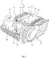
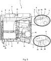
- Fig. 1 shows a schematic and perspective view of an embodiment of an inventive floor assembly 1 for not shown a device for drying laundry.
- the floor assembly 1 has a basic structure 2, which serves for holding various components of the floor assembly 1 and on which a supply air section 3 and an exhaust air section 4 of a not shown process air system of the device are formed, which are each communicatively connected to a heat exchanger housing 5 of the underbody 1, in which a thermally coupled to the process air system heat pump 6 with heat exchangers 7 (evaporator) and 8 (condenser) is arranged.
- the heat exchanger housing 5 has a in the FIGS. 2 to 4 shown Aufstellboden on which the heat exchangers 7 and 8 are placed, and a heat exchanger 7 and 8 on a side facing away from the top floor covering cover 9.
- the heat pump 6 also has a compressor 10 and an expansion unit 11, which are connected via refrigerant lines 12 of the heat pump 6 to the heat exchangers 7 and 8. At least one heat exchanger 7 or 8 and / or the cover member 9 are or is connected via at least one latching connection, not shown, with the heat exchanger housing 5.
- the cover part 9 has a cover element 13 covering the heat exchangers 7 and 8 on the side facing away from the erection floor and two projections 14 connected to the cover element 13 and extending parallel to one another, spaced apart from each other and extending at least as far as the installation floor Fig. 1 only a projection 14 is shown, which extend partially between the heat exchangers 7 and 8 and contact them at least indirectly.
- a trained between the heat exchangers 7 and 8, in the Fign 3 . 5 and 7A shown channel portion of the process air system is on a side facing away from the floor by means of a in the FIGS. 3 . 4 . 7A and 7B sealing element shown, which is arranged on a side facing the floor of the cover element 13, and laterally sealed by the projections 14 airtight.
- the sealing element is a flexible, elastically deformable mat, which in addition to the lid member 13 facing sides of the heat exchanger 7 and 8 covering, as it is in the FIGS. 3 . 4 . 7A and 7B is shown.
- the sealing element may be materially connected to the side of the cover element 13 facing the erection floor.
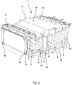
- Fig. 2 shows a schematic and perspective view of a portion of in Fig. 1 shown bottom group 1. It is only the heat exchanger housing 5 with the heat exchangers 7 and 8 arranged therein. It can be seen that the projections 14 engage in formed on the floor 16 recesses 23.
- Each heat exchanger 7 and 8 has at one in the Fign 3 . 5 and 7A shown side facing two channel over a height of the respective heat exchanger 7 and 8 extending lateral contact flanges 15, of which in Fig. 2 only one contact flange 15 is shown and each of which is in at least indirect contact with one of the projections 14.
- the contact flanges 15 are resilient and / or arranged. With the same projection 14 in at least indirect contact contact flanges 15 are arranged in opposite directions inclined to each other, that a distance between these contact flanges 15 in the direction of the floor 16 of the heat exchanger housing 5 is continuously reduced.
- Each projection 14 has in accordance with the contact flanges 15 in contact therewith in opposite directions inclined contact surfaces 17.
- Each heat exchanger 7 and 8 is arranged between the projections 14 and on a side opposite the projections 14 of the respective heat exchanger 7 and 8, in the height direction transverse to the floor 16 and parallel to each other, spaced from each other, arranged in Fig. 5 clamped shown wall elements of the heat exchanger housing 5.
- Each wall element extends over the height of the respective heat exchanger 7 or 8.
- Each heat exchanger 7 or 8 has on a side facing away from the channel section two over the height of the respective heat exchanger 7 and 8 extending lateral contact flanges 18, each in at least standing in indirect contact with each one of the wall elements.
- At one of the respective heat exchanger 7 and 8 facing side of the respective wall element are in Fig. 5 shown to be above a height of Wall element extending sealing ribs formed.
- Between at least one wall element and at least one contact flange 18 may be arranged at least one sealing element, not shown, which extends over at least a part of the height of the wall element.
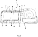
- Fig. 3 shows a schematic sectional view of in Fig. 1 shown bottom group 1 in the region of the projections 14. It can be seen between the cover member 13 and the heat exchanger 8 clamped portion of the sealing member 19. In addition, a trained on the raised floor 16 drain 20 can be seen, via which a guided over the heat exchanger 8 rinsing liquid can flow. Furthermore, the lying between the projections 14 channel portion 21 of the process air system can be seen.
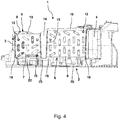
- Fig. 4 shows a further schematic sectional view of in Fig. 1
- a drain 22 can be seen on the floor 16, via which a condensate formed on the heat exchanger 7 can flow.
- the sealing element 19 is arranged continuously on the cover element 13.
- Fig. 5 shows a plan view of in Fig. 1 shown floor group 1 without the cover.
- the contact flanges 18 of the heat exchanger 8 are each connected via two formed on the respective wall member 24 sealing ribs 25 with the respective wall element 24 and that the contact flanges 18 of the heat exchanger 7 each have three on the respective wall element 26th trained sealing ribs 25 are connected to the respective wall element 26.
- Fig. 6 shows a schematic and perspective view of the in Fig. 1 The monolithic connection of the projections 14 with the cover element 13 and the wedge-shaped configuration of the projections 14 can be seen.
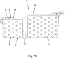
- Fig. 7A shows a schematic representation of a detail of in Fig. 1 shown floor assembly 1 in an assembled state.
- the projections 14 are urged between the heat exchangers 7 and 8 according to the arrow 27.
- the Heat exchangers 7 and 8 By contact of the projections 14 with the heat exchangers 7 and 8 are the Heat exchangers 7 and 8 in this case pushed away from each other according to the arrows 28 and 29 and pressed against the respective wall elements, not shown.
- Fig. 7B shows a schematic representation of the in Fig. 7A shown details in another mounting state.
- This mounting state is characterized by the in Fig. 7A shown mounting state that the projections 14 have been brought into their end positions shown and thus keep the heat exchanger 7 and 8 securely in the positions shown.
Landscapes
- Engineering & Computer Science (AREA)
- Textile Engineering (AREA)
- Detail Structures Of Washing Machines And Dryers (AREA)
- Main Body Construction Of Washing Machines And Laundry Dryers (AREA)
- Heat-Exchange Devices With Radiators And Conduit Assemblies (AREA)
Priority Applications (1)
| Application Number | Priority Date | Filing Date | Title |
|---|---|---|---|
| PL19164919T PL3556929T3 (pl) | 2018-04-16 | 2019-03-25 | Zespół dolny do urządzenia do suszenia prania |
Applications Claiming Priority (1)
| Application Number | Priority Date | Filing Date | Title |
|---|---|---|---|
| DE102018205734.6A DE102018205734A1 (de) | 2018-04-16 | 2018-04-16 | Bodengruppe für ein Gerät zum Trocknen von Wäsche |
Publications (2)
| Publication Number | Publication Date |
|---|---|
| EP3556929A1 true EP3556929A1 (fr) | 2019-10-23 |
| EP3556929B1 EP3556929B1 (fr) | 2020-12-23 |
Family
ID=65911092
Family Applications (1)
| Application Number | Title | Priority Date | Filing Date |
|---|---|---|---|
| EP19164919.3A Active EP3556929B1 (fr) | 2018-04-16 | 2019-03-25 | Module inférieur pour un appareil de séchage du linge |
Country Status (4)
| Country | Link |
|---|---|
| EP (1) | EP3556929B1 (fr) |
| CN (1) | CN110387726B (fr) |
| DE (1) | DE102018205734A1 (fr) |
| PL (1) | PL3556929T3 (fr) |
Cited By (2)
| Publication number | Priority date | Publication date | Assignee | Title |
|---|---|---|---|---|
| CN113529380A (zh) * | 2020-04-21 | 2021-10-22 | 无锡小天鹅电器有限公司 | 用于干衣机的底座组件及具有其的干衣机 |
| WO2023071907A1 (fr) * | 2021-10-26 | 2023-05-04 | 青岛海尔洗衣机有限公司 | Lave-linge séchant intégré de type à tambour |
Families Citing this family (3)
| Publication number | Priority date | Publication date | Assignee | Title |
|---|---|---|---|---|
| CN111021015B (zh) * | 2019-12-17 | 2022-04-29 | 无锡小天鹅电器有限公司 | 衣物处理设备及其底座组件 |
| DE102020201130A1 (de) | 2020-01-30 | 2021-08-05 | BSH Hausgeräte GmbH | Anordnung von Wärmetauschern einer Wärmepumpe eines Wäschetrockners |
| DE102020116400A1 (de) | 2020-06-22 | 2021-12-23 | Miele & Cie. Kg | Wärmetauschervorrichtung für ein Haushaltsgerät zur Erwärmung einer Prozessluft |
Citations (2)
| Publication number | Priority date | Publication date | Assignee | Title |
|---|---|---|---|---|
| WO2007013277A1 (fr) * | 2005-07-26 | 2007-02-01 | Kabushiki Kaisha Toshiba | Machine a laver / seche-linge a tambour |
| EP3124682A1 (fr) | 2015-07-27 | 2017-02-01 | Electrolux Appliances Aktiebolag | Sèche-linge à pompe à chaleur |
Family Cites Families (4)
| Publication number | Priority date | Publication date | Assignee | Title |
|---|---|---|---|---|
| KR101542389B1 (ko) * | 2009-02-05 | 2015-08-06 | 엘지전자 주식회사 | 히트펌프모듈 및 히트펌프모듈을 이용한 건조장치 |
| EP2708638A1 (fr) * | 2012-09-13 | 2014-03-19 | Electrolux Home Products Corporation N.V. | Sèche-linge à tambour rotatif |
| JP2014140440A (ja) * | 2013-01-23 | 2014-08-07 | Panasonic Corp | 乾燥機 |
| CN106367932A (zh) * | 2016-09-30 | 2017-02-01 | 无锡小天鹅股份有限公司 | 干衣机 |
-
2018
- 2018-04-16 DE DE102018205734.6A patent/DE102018205734A1/de not_active Withdrawn
-
2019
- 2019-03-25 EP EP19164919.3A patent/EP3556929B1/fr active Active
- 2019-03-25 PL PL19164919T patent/PL3556929T3/pl unknown
- 2019-04-10 CN CN201910283542.7A patent/CN110387726B/zh active Active
Patent Citations (2)
| Publication number | Priority date | Publication date | Assignee | Title |
|---|---|---|---|---|
| WO2007013277A1 (fr) * | 2005-07-26 | 2007-02-01 | Kabushiki Kaisha Toshiba | Machine a laver / seche-linge a tambour |
| EP3124682A1 (fr) | 2015-07-27 | 2017-02-01 | Electrolux Appliances Aktiebolag | Sèche-linge à pompe à chaleur |
Cited By (3)
| Publication number | Priority date | Publication date | Assignee | Title |
|---|---|---|---|---|
| CN113529380A (zh) * | 2020-04-21 | 2021-10-22 | 无锡小天鹅电器有限公司 | 用于干衣机的底座组件及具有其的干衣机 |
| CN113529380B (zh) * | 2020-04-21 | 2023-04-21 | 无锡小天鹅电器有限公司 | 用于干衣机的底座组件及具有其的干衣机 |
| WO2023071907A1 (fr) * | 2021-10-26 | 2023-05-04 | 青岛海尔洗衣机有限公司 | Lave-linge séchant intégré de type à tambour |
Also Published As
| Publication number | Publication date |
|---|---|
| EP3556929B1 (fr) | 2020-12-23 |
| DE102018205734A1 (de) | 2019-10-17 |
| CN110387726B (zh) | 2023-03-17 |
| CN110387726A (zh) | 2019-10-29 |
| PL3556929T3 (pl) | 2021-06-28 |
Similar Documents
| Publication | Publication Date | Title |
|---|---|---|
| EP3556929B1 (fr) | Module inférieur pour un appareil de séchage du linge | |
| EP1614559A1 (fr) | Climatiseur pour installation mobile | |
| DE102009022608A1 (de) | Kraftstoffzufuhrvorrichtung | |
| DE102022211916A1 (de) | Wärmeübertrager und Kältemittelmodul eines integrierten Wärmemanagementsystems für ein Fahrzeug umfassend dasselbe | |
| EP3155161A1 (fr) | Module inférieur pour sèche-linge et sèche-linge équipé d'un tel module | |
| DE102020121629A1 (de) | Induktionskochfeld und Verfahren zu dessen Herstellung | |
| WO2007031470A2 (fr) | Appareil frigorifique sans givre | |
| DE102008050376A1 (de) | Wärmetauscher für ein Klimatisierungsgerät | |
| DE19824461A1 (de) | Einbaufertiges Klimatisierungsmodul, insbesondere für Schienenfahrzeuge | |
| DE202013103846U1 (de) | Filterlüfteranordnung zur Kühlung eines Schaltschrankes | |
| EP4137339A1 (fr) | Dispositif d'évacuation d'eau pour un véhicule | |
| DE102006010553A1 (de) | Lüftungsanlage | |
| EP2827067A2 (fr) | Cadre central pour hotte aspirante et hotte aspirante | |
| DE102020110906A1 (de) | Batteriegehäuse | |
| DE2724880C2 (de) | Kastenförmiger, an einen Schaltschrank vorzugsweise ansetzbarer Kühler | |
| DE102018210525A1 (de) | Bodengruppe für ein Gerät zum Trocknen von Wäsche | |
| EP1672294A2 (fr) | Système de conditionnement d'air | |
| WO2022194552A1 (fr) | Appareil de réfrigération et ensemble échangeur de chaleur destiné à un appareil de réfrigération | |
| DE4222837A1 (de) | Anordnung eines Kondensators in einem Fahrzeug | |
| LU103281B1 (de) | Wäschebehandlungsgerät mit einem Gehäuse | |
| DE102015206492A1 (de) | Wärmetauscheranordnung für eine Wäschebehandlungsmaschine | |
| DE102017209839A1 (de) | Bodengruppe einer Wäschebehandlungsvorrichtung sowie Haushaltsgerät mit einer Bodengruppe | |
| DE112018008172B4 (de) | Zierblende und Innenraumeinheit | |
| DE102022002794A1 (de) | Klimagerät zur Montage auf einem Dach | |
| DE102012220982B3 (de) | Kühlanordnung mit unterschiedlichen Klimazonen |
Legal Events
| Date | Code | Title | Description |
|---|---|---|---|
| PUAI | Public reference made under article 153(3) epc to a published international application that has entered the european phase |
Free format text: ORIGINAL CODE: 0009012 |
|
| STAA | Information on the status of an ep patent application or granted ep patent |
Free format text: STATUS: THE APPLICATION HAS BEEN PUBLISHED |
|
| AK | Designated contracting states |
Kind code of ref document: A1 Designated state(s): AL AT BE BG CH CY CZ DE DK EE ES FI FR GB GR HR HU IE IS IT LI LT LU LV MC MK MT NL NO PL PT RO RS SE SI SK SM TR |
|
| AX | Request for extension of the european patent |
Extension state: BA ME |
|
| STAA | Information on the status of an ep patent application or granted ep patent |
Free format text: STATUS: REQUEST FOR EXAMINATION WAS MADE |
|
| 17P | Request for examination filed |
Effective date: 20200423 |
|
| RBV | Designated contracting states (corrected) |
Designated state(s): AL AT BE BG CH CY CZ DE DK EE ES FI FR GB GR HR HU IE IS IT LI LT LU LV MC MK MT NL NO PL PT RO RS SE SI SK SM TR |
|
| GRAP | Despatch of communication of intention to grant a patent |
Free format text: ORIGINAL CODE: EPIDOSNIGR1 |
|
| STAA | Information on the status of an ep patent application or granted ep patent |
Free format text: STATUS: GRANT OF PATENT IS INTENDED |
|
| RIC1 | Information provided on ipc code assigned before grant |
Ipc: D06F 58/20 20060101AFI20200727BHEP |
|
| INTG | Intention to grant announced |
Effective date: 20200820 |
|
| GRAS | Grant fee paid |
Free format text: ORIGINAL CODE: EPIDOSNIGR3 |
|
| GRAA | (expected) grant |
Free format text: ORIGINAL CODE: 0009210 |
|
| STAA | Information on the status of an ep patent application or granted ep patent |
Free format text: STATUS: THE PATENT HAS BEEN GRANTED |
|
| AK | Designated contracting states |
Kind code of ref document: B1 Designated state(s): AL AT BE BG CH CY CZ DE DK EE ES FI FR GB GR HR HU IE IS IT LI LT LU LV MC MK MT NL NO PL PT RO RS SE SI SK SM TR |
|
| REG | Reference to a national code |
Ref country code: GB Ref legal event code: FG4D Free format text: NOT ENGLISH |
|
| REG | Reference to a national code |
Ref country code: DE Ref legal event code: R096 Ref document number: 502019000564 Country of ref document: DE |
|
| REG | Reference to a national code |
Ref country code: AT Ref legal event code: REF Ref document number: 1347842 Country of ref document: AT Kind code of ref document: T Effective date: 20210115 |
|
| REG | Reference to a national code |
Ref country code: IE Ref legal event code: FG4D Free format text: LANGUAGE OF EP DOCUMENT: GERMAN |
|
| PG25 | Lapsed in a contracting state [announced via postgrant information from national office to epo] |
Ref country code: GR Free format text: LAPSE BECAUSE OF FAILURE TO SUBMIT A TRANSLATION OF THE DESCRIPTION OR TO PAY THE FEE WITHIN THE PRESCRIBED TIME-LIMIT Effective date: 20210324 Ref country code: NO Free format text: LAPSE BECAUSE OF FAILURE TO SUBMIT A TRANSLATION OF THE DESCRIPTION OR TO PAY THE FEE WITHIN THE PRESCRIBED TIME-LIMIT Effective date: 20210323 Ref country code: RS Free format text: LAPSE BECAUSE OF FAILURE TO SUBMIT A TRANSLATION OF THE DESCRIPTION OR TO PAY THE FEE WITHIN THE PRESCRIBED TIME-LIMIT Effective date: 20201223 Ref country code: FI Free format text: LAPSE BECAUSE OF FAILURE TO SUBMIT A TRANSLATION OF THE DESCRIPTION OR TO PAY THE FEE WITHIN THE PRESCRIBED TIME-LIMIT Effective date: 20201223 |
|
| REG | Reference to a national code |
Ref country code: NL Ref legal event code: MP Effective date: 20201223 |
|
| PG25 | Lapsed in a contracting state [announced via postgrant information from national office to epo] |
Ref country code: LV Free format text: LAPSE BECAUSE OF FAILURE TO SUBMIT A TRANSLATION OF THE DESCRIPTION OR TO PAY THE FEE WITHIN THE PRESCRIBED TIME-LIMIT Effective date: 20201223 Ref country code: SE Free format text: LAPSE BECAUSE OF FAILURE TO SUBMIT A TRANSLATION OF THE DESCRIPTION OR TO PAY THE FEE WITHIN THE PRESCRIBED TIME-LIMIT Effective date: 20201223 Ref country code: BG Free format text: LAPSE BECAUSE OF FAILURE TO SUBMIT A TRANSLATION OF THE DESCRIPTION OR TO PAY THE FEE WITHIN THE PRESCRIBED TIME-LIMIT Effective date: 20210323 |
|
| PG25 | Lapsed in a contracting state [announced via postgrant information from national office to epo] |
Ref country code: NL Free format text: LAPSE BECAUSE OF FAILURE TO SUBMIT A TRANSLATION OF THE DESCRIPTION OR TO PAY THE FEE WITHIN THE PRESCRIBED TIME-LIMIT Effective date: 20201223 Ref country code: HR Free format text: LAPSE BECAUSE OF FAILURE TO SUBMIT A TRANSLATION OF THE DESCRIPTION OR TO PAY THE FEE WITHIN THE PRESCRIBED TIME-LIMIT Effective date: 20201223 |
|
| REG | Reference to a national code |
Ref country code: LT Ref legal event code: MG9D |
|
| PG25 | Lapsed in a contracting state [announced via postgrant information from national office to epo] |
Ref country code: SK Free format text: LAPSE BECAUSE OF FAILURE TO SUBMIT A TRANSLATION OF THE DESCRIPTION OR TO PAY THE FEE WITHIN THE PRESCRIBED TIME-LIMIT Effective date: 20201223 Ref country code: SM Free format text: LAPSE BECAUSE OF FAILURE TO SUBMIT A TRANSLATION OF THE DESCRIPTION OR TO PAY THE FEE WITHIN THE PRESCRIBED TIME-LIMIT Effective date: 20201223 Ref country code: EE Free format text: LAPSE BECAUSE OF FAILURE TO SUBMIT A TRANSLATION OF THE DESCRIPTION OR TO PAY THE FEE WITHIN THE PRESCRIBED TIME-LIMIT Effective date: 20201223 Ref country code: CZ Free format text: LAPSE BECAUSE OF FAILURE TO SUBMIT A TRANSLATION OF THE DESCRIPTION OR TO PAY THE FEE WITHIN THE PRESCRIBED TIME-LIMIT Effective date: 20201223 Ref country code: LT Free format text: LAPSE BECAUSE OF FAILURE TO SUBMIT A TRANSLATION OF THE DESCRIPTION OR TO PAY THE FEE WITHIN THE PRESCRIBED TIME-LIMIT Effective date: 20201223 Ref country code: PT Free format text: LAPSE BECAUSE OF FAILURE TO SUBMIT A TRANSLATION OF THE DESCRIPTION OR TO PAY THE FEE WITHIN THE PRESCRIBED TIME-LIMIT Effective date: 20210423 Ref country code: RO Free format text: LAPSE BECAUSE OF FAILURE TO SUBMIT A TRANSLATION OF THE DESCRIPTION OR TO PAY THE FEE WITHIN THE PRESCRIBED TIME-LIMIT Effective date: 20201223 |
|
| REG | Reference to a national code |
Ref country code: DE Ref legal event code: R097 Ref document number: 502019000564 Country of ref document: DE |
|
| PG25 | Lapsed in a contracting state [announced via postgrant information from national office to epo] |
Ref country code: IS Free format text: LAPSE BECAUSE OF FAILURE TO SUBMIT A TRANSLATION OF THE DESCRIPTION OR TO PAY THE FEE WITHIN THE PRESCRIBED TIME-LIMIT Effective date: 20210423 |
|
| PG25 | Lapsed in a contracting state [announced via postgrant information from national office to epo] |
Ref country code: AL Free format text: LAPSE BECAUSE OF FAILURE TO SUBMIT A TRANSLATION OF THE DESCRIPTION OR TO PAY THE FEE WITHIN THE PRESCRIBED TIME-LIMIT Effective date: 20201223 Ref country code: MC Free format text: LAPSE BECAUSE OF FAILURE TO SUBMIT A TRANSLATION OF THE DESCRIPTION OR TO PAY THE FEE WITHIN THE PRESCRIBED TIME-LIMIT Effective date: 20201223 Ref country code: IT Free format text: LAPSE BECAUSE OF FAILURE TO SUBMIT A TRANSLATION OF THE DESCRIPTION OR TO PAY THE FEE WITHIN THE PRESCRIBED TIME-LIMIT Effective date: 20201223 |
|
| PLBE | No opposition filed within time limit |
Free format text: ORIGINAL CODE: 0009261 |
|
| STAA | Information on the status of an ep patent application or granted ep patent |
Free format text: STATUS: NO OPPOSITION FILED WITHIN TIME LIMIT |
|
| PG25 | Lapsed in a contracting state [announced via postgrant information from national office to epo] |
Ref country code: DK Free format text: LAPSE BECAUSE OF FAILURE TO SUBMIT A TRANSLATION OF THE DESCRIPTION OR TO PAY THE FEE WITHIN THE PRESCRIBED TIME-LIMIT Effective date: 20201223 |
|
| 26N | No opposition filed |
Effective date: 20210924 |
|
| REG | Reference to a national code |
Ref country code: BE Ref legal event code: MM Effective date: 20210331 |
|
| PG25 | Lapsed in a contracting state [announced via postgrant information from national office to epo] |
Ref country code: FR Free format text: LAPSE BECAUSE OF NON-PAYMENT OF DUE FEES Effective date: 20210331 Ref country code: LU Free format text: LAPSE BECAUSE OF NON-PAYMENT OF DUE FEES Effective date: 20210325 Ref country code: IE Free format text: LAPSE BECAUSE OF NON-PAYMENT OF DUE FEES Effective date: 20210325 Ref country code: ES Free format text: LAPSE BECAUSE OF FAILURE TO SUBMIT A TRANSLATION OF THE DESCRIPTION OR TO PAY THE FEE WITHIN THE PRESCRIBED TIME-LIMIT Effective date: 20201223 |
|
| PG25 | Lapsed in a contracting state [announced via postgrant information from national office to epo] |
Ref country code: SI Free format text: LAPSE BECAUSE OF FAILURE TO SUBMIT A TRANSLATION OF THE DESCRIPTION OR TO PAY THE FEE WITHIN THE PRESCRIBED TIME-LIMIT Effective date: 20201223 |
|
| PG25 | Lapsed in a contracting state [announced via postgrant information from national office to epo] |
Ref country code: IS Free format text: LAPSE BECAUSE OF FAILURE TO SUBMIT A TRANSLATION OF THE DESCRIPTION OR TO PAY THE FEE WITHIN THE PRESCRIBED TIME-LIMIT Effective date: 20210423 |
|
| PG25 | Lapsed in a contracting state [announced via postgrant information from national office to epo] |
Ref country code: BE Free format text: LAPSE BECAUSE OF NON-PAYMENT OF DUE FEES Effective date: 20210331 |
|
| REG | Reference to a national code |
Ref country code: CH Ref legal event code: PL |
|
| PG25 | Lapsed in a contracting state [announced via postgrant information from national office to epo] |
Ref country code: LI Free format text: LAPSE BECAUSE OF NON-PAYMENT OF DUE FEES Effective date: 20220331 Ref country code: CH Free format text: LAPSE BECAUSE OF NON-PAYMENT OF DUE FEES Effective date: 20220331 |
|
| REG | Reference to a national code |
Ref country code: DE Ref legal event code: R084 Ref document number: 502019000564 Country of ref document: DE |
|
| PGFP | Annual fee paid to national office [announced via postgrant information from national office to epo] |
Ref country code: PL Payment date: 20230313 Year of fee payment: 5 |
|
| REG | Reference to a national code |
Ref country code: DE Ref legal event code: R085 Ref document number: 502019000564 Country of ref document: DE |
|
| PG25 | Lapsed in a contracting state [announced via postgrant information from national office to epo] |
Ref country code: CY Free format text: LAPSE BECAUSE OF FAILURE TO SUBMIT A TRANSLATION OF THE DESCRIPTION OR TO PAY THE FEE WITHIN THE PRESCRIBED TIME-LIMIT Effective date: 20201223 |
|
| PG25 | Lapsed in a contracting state [announced via postgrant information from national office to epo] |
Ref country code: HU Free format text: LAPSE BECAUSE OF FAILURE TO SUBMIT A TRANSLATION OF THE DESCRIPTION OR TO PAY THE FEE WITHIN THE PRESCRIBED TIME-LIMIT; INVALID AB INITIO Effective date: 20190325 |
|
| GBPC | Gb: european patent ceased through non-payment of renewal fee |
Effective date: 20230325 |
|
| PG25 | Lapsed in a contracting state [announced via postgrant information from national office to epo] |
Ref country code: GB Free format text: LAPSE BECAUSE OF NON-PAYMENT OF DUE FEES Effective date: 20230325 |
|
| PG25 | Lapsed in a contracting state [announced via postgrant information from national office to epo] |
Ref country code: GB Free format text: LAPSE BECAUSE OF NON-PAYMENT OF DUE FEES Effective date: 20230325 |
|
| PG25 | Lapsed in a contracting state [announced via postgrant information from national office to epo] |
Ref country code: MK Free format text: LAPSE BECAUSE OF FAILURE TO SUBMIT A TRANSLATION OF THE DESCRIPTION OR TO PAY THE FEE WITHIN THE PRESCRIBED TIME-LIMIT Effective date: 20201223 |
|
| PG25 | Lapsed in a contracting state [announced via postgrant information from national office to epo] |
Ref country code: MT Free format text: LAPSE BECAUSE OF FAILURE TO SUBMIT A TRANSLATION OF THE DESCRIPTION OR TO PAY THE FEE WITHIN THE PRESCRIBED TIME-LIMIT Effective date: 20201223 |
|
| PGFP | Annual fee paid to national office [announced via postgrant information from national office to epo] |
Ref country code: DE Payment date: 20250331 Year of fee payment: 7 |
|
| PGFP | Annual fee paid to national office [announced via postgrant information from national office to epo] |
Ref country code: TR Payment date: 20250319 Year of fee payment: 7 |
|
| REG | Reference to a national code |
Ref country code: AT Ref legal event code: MM01 Ref document number: 1347842 Country of ref document: AT Kind code of ref document: T Effective date: 20240325 |
|
| PG25 | Lapsed in a contracting state [announced via postgrant information from national office to epo] |
Ref country code: AT Free format text: LAPSE BECAUSE OF NON-PAYMENT OF DUE FEES Effective date: 20240325 |
|
| PG25 | Lapsed in a contracting state [announced via postgrant information from national office to epo] |
Ref country code: PL Free format text: LAPSE BECAUSE OF NON-PAYMENT OF DUE FEES Effective date: 20240325 |