EP3556725A1 - Hahn für kohlensäurehaltiges wasser - Google Patents
Hahn für kohlensäurehaltiges wasser Download PDFInfo
- Publication number
- EP3556725A1 EP3556725A1 EP17880370.6A EP17880370A EP3556725A1 EP 3556725 A1 EP3556725 A1 EP 3556725A1 EP 17880370 A EP17880370 A EP 17880370A EP 3556725 A1 EP3556725 A1 EP 3556725A1
- Authority
- EP
- European Patent Office
- Prior art keywords
- carbonated water
- flow path
- water flow
- cock
- shaft
- Prior art date
- Legal status (The legal status is an assumption and is not a legal conclusion. Google has not performed a legal analysis and makes no representation as to the accuracy of the status listed.)
- Withdrawn
Links
- XLYOFNOQVPJJNP-UHFFFAOYSA-N water Substances O XLYOFNOQVPJJNP-UHFFFAOYSA-N 0.000 title claims abstract description 148
- 241000048246 Gallicrex cinerea Species 0.000 claims description 33
- 230000001747 exhibiting effect Effects 0.000 claims description 2
- 235000013361 beverage Nutrition 0.000 description 36
- 230000001105 regulatory effect Effects 0.000 description 8
- 239000011521 glass Substances 0.000 description 5
- 235000012174 carbonated soft drink Nutrition 0.000 description 3
- 238000001816 cooling Methods 0.000 description 3
- 230000000694 effects Effects 0.000 description 3
- 239000007788 liquid Substances 0.000 description 3
- 235000020357 syrup Nutrition 0.000 description 3
- 239000006188 syrup Substances 0.000 description 3
- 235000016795 Cola Nutrition 0.000 description 2
- 241001634499 Cola Species 0.000 description 2
- 235000011824 Cola pachycarpa Nutrition 0.000 description 2
- 235000013334 alcoholic beverage Nutrition 0.000 description 2
- 239000000498 cooling water Substances 0.000 description 2
- 238000005259 measurement Methods 0.000 description 2
- 239000000203 mixture Substances 0.000 description 2
- 235000015096 spirit Nutrition 0.000 description 2
- 235000013522 vodka Nutrition 0.000 description 2
- 235000015041 whisky Nutrition 0.000 description 2
- 238000005094 computer simulation Methods 0.000 description 1
- 238000007599 discharging Methods 0.000 description 1
- 239000012530 fluid Substances 0.000 description 1
- 238000012423 maintenance Methods 0.000 description 1
- 238000005086 pumping Methods 0.000 description 1
- 239000003507 refrigerant Substances 0.000 description 1
- 239000008399 tap water Substances 0.000 description 1
- 235000020679 tap water Nutrition 0.000 description 1
Images



Classifications
-
- B—PERFORMING OPERATIONS; TRANSPORTING
- B67—OPENING, CLOSING OR CLEANING BOTTLES, JARS OR SIMILAR CONTAINERS; LIQUID HANDLING
- B67D—DISPENSING, DELIVERING OR TRANSFERRING LIQUIDS, NOT OTHERWISE PROVIDED FOR
- B67D1/00—Apparatus or devices for dispensing beverages on draught
- B67D1/08—Details
- B67D1/12—Flow or pressure control devices or systems, e.g. valves, gas pressure control, level control in storage containers
- B67D1/14—Reducing valves or control taps
- B67D1/1405—Control taps
- B67D1/145—Control taps comprising a valve shutter movable in a direction perpendicular to the valve seat
- B67D1/1455—Control taps comprising a valve shutter movable in a direction perpendicular to the valve seat the valve shutter being opened in the same direction as the liquid flow
-
- B—PERFORMING OPERATIONS; TRANSPORTING
- B67—OPENING, CLOSING OR CLEANING BOTTLES, JARS OR SIMILAR CONTAINERS; LIQUID HANDLING
- B67D—DISPENSING, DELIVERING OR TRANSFERRING LIQUIDS, NOT OTHERWISE PROVIDED FOR
- B67D1/00—Apparatus or devices for dispensing beverages on draught
- B67D1/08—Details
- B67D1/12—Flow or pressure control devices or systems, e.g. valves, gas pressure control, level control in storage containers
- B67D1/1277—Flow control valves
-
- B—PERFORMING OPERATIONS; TRANSPORTING
- B67—OPENING, CLOSING OR CLEANING BOTTLES, JARS OR SIMILAR CONTAINERS; LIQUID HANDLING
- B67D—DISPENSING, DELIVERING OR TRANSFERRING LIQUIDS, NOT OTHERWISE PROVIDED FOR
- B67D1/00—Apparatus or devices for dispensing beverages on draught
- B67D1/08—Details
- B67D1/12—Flow or pressure control devices or systems, e.g. valves, gas pressure control, level control in storage containers
- B67D1/14—Reducing valves or control taps
-
- B—PERFORMING OPERATIONS; TRANSPORTING
- B67—OPENING, CLOSING OR CLEANING BOTTLES, JARS OR SIMILAR CONTAINERS; LIQUID HANDLING
- B67D—DISPENSING, DELIVERING OR TRANSFERRING LIQUIDS, NOT OTHERWISE PROVIDED FOR
- B67D1/00—Apparatus or devices for dispensing beverages on draught
- B67D1/0042—Details of specific parts of the dispensers
- B67D1/0043—Mixing devices for liquids
- B67D1/0044—Mixing devices for liquids for mixing inside the dispensing nozzle
- B67D1/0046—Mixing chambers
- B67D1/005—Mixing chambers with means for converging streams
-
- B—PERFORMING OPERATIONS; TRANSPORTING
- B67—OPENING, CLOSING OR CLEANING BOTTLES, JARS OR SIMILAR CONTAINERS; LIQUID HANDLING
- B67D—DISPENSING, DELIVERING OR TRANSFERRING LIQUIDS, NOT OTHERWISE PROVIDED FOR
- B67D1/00—Apparatus or devices for dispensing beverages on draught
- B67D1/04—Apparatus utilising compressed air or other gas acting directly or indirectly on beverages in storage containers
- B67D1/0406—Apparatus utilising compressed air or other gas acting directly or indirectly on beverages in storage containers with means for carbonating the beverage, or for maintaining its carbonation
-
- B—PERFORMING OPERATIONS; TRANSPORTING
- B67—OPENING, CLOSING OR CLEANING BOTTLES, JARS OR SIMILAR CONTAINERS; LIQUID HANDLING
- B67D—DISPENSING, DELIVERING OR TRANSFERRING LIQUIDS, NOT OTHERWISE PROVIDED FOR
- B67D1/00—Apparatus or devices for dispensing beverages on draught
- B67D1/08—Details
- B67D1/12—Flow or pressure control devices or systems, e.g. valves, gas pressure control, level control in storage containers
-
- B—PERFORMING OPERATIONS; TRANSPORTING
- B67—OPENING, CLOSING OR CLEANING BOTTLES, JARS OR SIMILAR CONTAINERS; LIQUID HANDLING
- B67D—DISPENSING, DELIVERING OR TRANSFERRING LIQUIDS, NOT OTHERWISE PROVIDED FOR
- B67D1/00—Apparatus or devices for dispensing beverages on draught
- B67D1/0015—Apparatus or devices for dispensing beverages on draught the beverage being prepared by mixing at least two liquid components
- B67D1/0021—Apparatus or devices for dispensing beverages on draught the beverage being prepared by mixing at least two liquid components the components being mixed at the time of dispensing, i.e. post-mix dispensers
- B67D1/0022—Apparatus or devices for dispensing beverages on draught the beverage being prepared by mixing at least two liquid components the components being mixed at the time of dispensing, i.e. post-mix dispensers the apparatus comprising means for automatically controlling the amount to be dispensed
- B67D1/0034—Apparatus or devices for dispensing beverages on draught the beverage being prepared by mixing at least two liquid components the components being mixed at the time of dispensing, i.e. post-mix dispensers the apparatus comprising means for automatically controlling the amount to be dispensed for controlling the amount of each component
- B67D1/0035—Apparatus or devices for dispensing beverages on draught the beverage being prepared by mixing at least two liquid components the components being mixed at the time of dispensing, i.e. post-mix dispensers the apparatus comprising means for automatically controlling the amount to be dispensed for controlling the amount of each component the controls being based on the same metering technics
-
- B—PERFORMING OPERATIONS; TRANSPORTING
- B67—OPENING, CLOSING OR CLEANING BOTTLES, JARS OR SIMILAR CONTAINERS; LIQUID HANDLING
- B67D—DISPENSING, DELIVERING OR TRANSFERRING LIQUIDS, NOT OTHERWISE PROVIDED FOR
- B67D1/00—Apparatus or devices for dispensing beverages on draught
- B67D1/0042—Details of specific parts of the dispensers
- B67D1/0057—Carbonators
- B67D1/0061—Carbonators with cooling means
- B67D1/0066—Carbonators with cooling means outside the carbonator
- B67D1/0068—Cooling bath
Definitions
- the present invention relates to a carbonated water cock for dispensing carbonated water for beverage use.
- Carbonated water servers mixing carbonated water with vodka, whisky, or other distilled spirits or syrups or colas to provide carbonated alcoholic beverages or carbonated soft drinks are being widely used in restaurants etc.
- Carbonated water servers are usually provided with carbonated gas tanks, carbonation tanks storing carbonated water under pressure, bottles of distilled spirits or syrups etc. (below, referred to as "beverage base"), beverage base pumps, and carbonated water cocks which mix the carbonated water with the beverage base and dispense the beverage into glasses.
- the carbonation tank is supplied with relatively high pressure CO 2 gas for dissolving CO 2 gas in water to produce carbonated water.
- the CO 2 gas volume of the carbonated water is adjusted by the CO 2 gas pressure acting on the carbonation tank.
- the CO 2 gas volume of the carbonated water is highest at the carbonation tank, falls while passing through the carbonated water cock etc. and is lowest in the glass.
- PTL 1 describes a hand draft-type beverage dispenser for mixing carbonated water and a plurality of types of beverage bases to provide carbonated soft drinks at restaurants etc.
- the present invention is made in consideration of the above situation and has as its object the provision of a carbonated water cock in which the CO 2 gas volume is kept from dropping.
- a carbonated water cock receiving pressurized carbonated water and discharging it from a nozzle, the carbonated water cock comprising a first carbonated water flow path, a second carbonated water flow path connected to a downstream side of the first carbonated water flow path, extending in a direction different from the first carbonated water flow path, and exhibiting an annular-shaped flow path cross section, wherein an outer diameter of the flow path is larger than the first carbonated water flow path, but a flow path sectional area is smaller than the first carbonated water flow path, and a shaft defining an inner circumferential surface of the annular shape of the second carbonated water flow path, the shaft having a ring-shaped groove formed around an outer circumference of the shaft at a part of the second carbonated water flow path connected to the first carbonated water flow path, a longitudinal center axis of the first carbonated water flow path not being parallel to and not intersecting a longitudinal center axis of the second carbonated water flow path.
- the carbonated water flowing in from the first carbonated water flow path to the second carbonated water flow path is changed in direction without rapidly being narrowed in flow path and without strongly striking the shaft.
- the drop in CO 2 gas volume of the carbonated water passing through the carbonated water cock is suppressed and therefore the pressure of the carbonation tank can be reduced by exactly an amount corresponding to the amount of drop suppressed.
- a carbonated water cock 10 according to an embodiment of the present invention will be explained below.
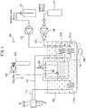
- a carbonated water server 100 provided with a carbonated water cock 10 according to an embodiment of the present invention will be explained.
- the carbonated water server 100 of FIG. 1 is a device for providing a carbonated alcoholic beverage obtained by mixing vodka or whisky or other beverage base with carbonated water.
- the carbonated water server 100 may also be one providing a carbonated soft drink obtained using a syrup or cola etc. as a beverage base.
- a bottle 101 in which a beverage base is stored a liquid pump 102 pumping the beverage base
- a CO 2 gas tank 104 with a pressure regulator 103 attached a carbonation tank 105 for dissolving the CO 2 gas in water to produce carbonated water
- a cooling water tank 106 for cooling the carbonation tank 105 a high pressure pump 108 supplying tap water filtered by a water purifying filter 107 to the carbonation tank 105
- a carbonated water cock 10 mixing the carbonated water and beverage base and dispensing the beverage into a glass etc.
- a cooling device 110 provided with a refrigerant compressor 109, etc.
- Supply pipelines 111,112,113 for the water, beverage base, and carbonated water are cooled at the cooling water tank 106 and have coil shaped parts 111a,112a,113a to improve the cooling efficiency.
- the carbonated water is pumped to the carbonated water cock 10 based on the pressure acting inside the carbonation tank 105.
- the beverage base is pumped by the liquid pump 102 to the carbonated water cock 10.
- the mixing ratio of the carbonated water and the beverage base is adjusted by adjusting the discharge pressure of the liquid pump 102.
- the CO 2 gas volume of the carbonated water is highest at the carbonation tank 105 and is lowest inside the glass (not shown) into which the beverage is dispensed from the carbonated water cock 10.
- the carbonated water cock 10 is provided with a valve unit 20 for independently manually opening and closing the carbonated water flow path and beverage base flow path and a cock main body part 30 arranged downstream of the valve unit 20.
- the cock main body part 30 has a novel characterizing configuration enabling a drop in CO 2 gas volume to be suppressed, while the valve unit 20 is a known one having the above-mentioned function. For this reason, in this Description, further explanation of the valve unit 20 will be omitted and the cock main body part 30 will be explained in detail below.
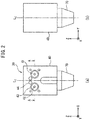
- FIG. 2 is a view showing the appearance of the cock main body part 30.
- (a) is a front view
- (b) is a right side view.
- orthogonal X-, Y-, and Z-axial directions are defined as shown in FIG. 2 and FIG. 3.
- FIG. 3 is a side sectional view cut so that the later-explained first carbonated water flow path 45 and second carbonated water flow path 46 are revealed.
- FIG. 4 is a sectional view at A-A of FIG. 2(a) .
- the cock main body part 30 has a substantially parallelepiped block-shaped main body 40, a shaft 50 arranged inside the main body 40, a flow regulating member 60 attached to the bottom end of the shaft 50, and a nozzle 70 attached to the bottom surface of the main body 40.
- the main body 40 as shown in FIG. 2(a) , has relatively small diameter carbonated water inlet 41 and beverage base inlet 42 provided substantially symmetrically across a center line Lz extending in the Z-direction.
- large diameter step-shaped recessed parts 43 are coaxially formed.
- a total of six holes 44 are formed around the step-shaped recessed parts 43. These step-shaped recessed parts 43 and holes 44 are provided for connection with the valve unit 20.
- the main body 40 has a first carbonated water flow path 45 extending horizontally from the carbonated water inlet 41 to the inside, a second carbonated water flow path 46 connected at a downstream end of the first carbonated water flow path 45 and extending vertically downward, and a first beverage base flow path 47 extending from the beverage base inlet 42 to the inside upward at an incline.
- the second carbonated water flow path 46 is defined by the inner circumferential surface of a center hole 48, constituted by a blind hole bored upward from the bottom part coaxially with the center line Lz of the main body 40, and by the outer circumferential surface of the shaft 50 which is of a smaller diameter than the center hole 48, the shaft 50 being fastened by being screwed into the center hole 48 coaxially.
- the second carbonated water flow path 46 is formed as an annular gap "g" between the outer circumferential surface of the shaft 50 and the inner circumferential surface of the center hole 48.
- the diameter of the first carbonated water flow path 45 is 3.5 mm, while the outer diameter of the second carbonated water flow path 46 is 11.1 mm or about 3 times larger.
- the second carbonated water flow path 46 is about 40% of that of the first carbonated water flow path 45.
- the shapes and flow path sectional areas of the first carbonated water flow path 45 and second carbonated water flow path 46 in the present embodiment explained above are set conditional on maintenance of a predetermined flow rate of supply while maintaining the flows inside the flow paths as laminar flows.
- the first beverage base flow path 47 extends from the beverage base inlet 42 upward at an incline so as to connect the inlet 42 and the outlet of the first beverage base flow path 47 formed at the inner circumferential surface near the top end part of the screw hole of the main body 40 used by the shaft.
- the shaft 50 has the second beverage base flow path 51 as a hole formed along its center axis.
- the inlet of the second beverage base flow path 51 is provided at the top end face of the shaft 50.
- the second beverage base flow path 51 extends along the center axis of the shaft 50 downwards from the top end and has four outlets branched radially at the outer circumferential surface near the bottom end. Note that the center axis of the shaft 50, the center axis Lz of the main body 40, and the longitudinal center axes C 2 of the second carbonated water flow path 46 match in the present embodiment.
- the flow regulating member 60 is screwed in to fasten it.
- the flow regulating member 60 is formed into a columnar shape having a semispherical front end.
- a circular recessed part 61 is formed at the inside of the top end part.
- the circular recessed part 61 has a diameter larger than the outer diameter of the second carbonated water flow path 46, so that it can receive the carbonated water flowing down along the second carbonated water flow path 46 and mix it with the beverage base flowing out from the outlets of the second beverage base flow path 51 provided at the shaft 50.
- the nozzle 70 has inside it a space able to house the flow regulating member 60 and is fastened by being screwed into the bottom surface of the main body 40 so as to surround the flow regulating member 60.
- the carbonated water and beverage base mixed inside the flow regulating member 60 pass through the gap between the top end face of the flow regulating member 60 and the bottom surface of the main body 40 to flow into the space in the nozzle 70, and are discharged downwardly from there.
- the longitudinal center axis C 1 of the first carbonated water flow path 45 and the longitudinal center axis C 2 of the second carbonated water flow path 46 vertically intersect when viewed in the X-direction ( FIG. 3 ), but do not intersect when viewed in the Z-direction ( FIG. 4 ).
- FIG. 3 The longitudinal center axis C 1 of the first carbonated water flow path 45 and the longitudinal center axis C 2 of the second carbonated water flow path 46
- the first carbonated water flow path 45 and the second carbonated water flow path 46 are connected so that among two lines showing a contour of the first carbonated water flow path 45, a line further from the longitudinal center axis C 2 of the second carbonated water flow path 46 is a tangent of a circle showing the outer diameter of the second carbonated water flow path 46.
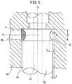
- the shaft 50 has a ring-shaped groove 52 formed around the outer circumference of the shaft 50 at the part of the second carbonated water flow path 46 connected to the first carbonated water flow path 45, in other words, the part where the longitudinal center axis C 1 of the first carbonated water flow path 45 intersects when viewed from the side in the X-direction.
- the ring-shaped groove 52 has a bow-shaped cross-section. In the present embodiment, the dimensions of the bow shape are set as a radius "r" of 2.5 mm, a chord "s" of 4 mm, and a height "h" of the arc of 1 mm.
- the gap "g" between the outer circumferential surface of the shaft 50 and the inner circumferential surface of the center hole 48 of the main body 40 is 0.1 mm.
- the area of the hatched region A made up of the bow-shaped area of the ring-shaped groove 52 when viewed from the side plus the area of the rectangular shape formed by the chord "s" of the bow shape and the width "g" of the second carbonated water flow path is, in the present embodiment, 3.2 mm 2 . This is 33% of the flow path sectional area of the first carbonated water flow path 45.
- the carbonated water flowing in from the horizontally-extending first carbonated water flow path 45 to the vertically downwardly-extending second carbonated water flow path 46 is changed in direction from the horizontal direction to downward without the flow path being rapidly narrowed and without striking the shaft 50 strongly.
- the CO 2 gas volume of the carbonated water is kept from dropping.
- the volume is 4.5V/V in the case of the first comparison-use carbonated water cock, while it is 4.8V/V in the case of the carbonated water cock 10 of the present embodiment. It is shown that there is an approximately 7% improvement.
- a second comparison-use carbonated water cock (not shown), in which the first carbonated water flow path 45 is connected to the second carbonated water flow path 46 in the tangential direction but there is no bow-shaped ring-shaped groove 52, and the carbonated water cock 10 of the present embodiment are compared.
- the results (measured values) are shown in FIG. 7 .
- the CO 2 gas volume of carbonated water is about 4.6 V/V in the case of the second comparison use carbonated water cock, while it is 4.8V/V in the case of the carbonated water cock 10 of the present embodiment. It is shown that there is an approximately 4% improvement.
- the depth of the ring-shaped groove 52 with a bow shape or the height "h" of the arc is set to 1 mm in the embodiment shown in FIG. 5 , but if it is too deep, the free space increases and thereby turbulence is caused and a drop in gas volume is invited.
- the upper limit value of the depth of the ring-shaped groove 52 for not allowing turbulence can be found from computer simulation. The result is 1.5 mm.
- the area of the region A of FIG. 5 when the depth of the ring-shaped groove 52 is 1.5 mm is 50% of the flow cross-sectional area of the first carbonated water flow path 45.
- the shallower the depth of the ring-shaped groove 52 from the optimum value gradually the more the CO 2 gas volume of the carbonated water drops, but compared with the case of having no ring-shaped groove 52 at all, the existence of the advantageous effect even with a shallow ring-shaped groove 52 can be understood from the measurement results shown in FIG. 7 .
- the first carbonated water flow path 45 when viewed in the Z-axial direction, is connected to the second carbonated water flow path 46 in the tangential direction, but so long as the longitudinal center axis C 1 of the first carbonated water flow path 45 is close to the longitudinal center axis C 2 of the second carbonated water flow path 46 but does not intersect it, even if not to the extent of the case of the above embodiment, the existence of the advantageous effect of the present invention can be understood from the measurement results shown in FIG. 6 .
- the longitudinal center axis C 1 of the first carbonated water flow path 45 and the longitudinal center axis C 2 of the second carbonated water flow path 46 intersect perpendicularly when seen from the side, but an embodiment in which the angle of intersection is other than perpendicular is also possible in the present invention.
- just one type of beverage base is supplied to the carbonated water cock 10, but an embodiment of a carbonated water cock to which a plurality of types of beverage bases are supplied is also possible in the present invention. Further, conversely, an embodiment in which no beverage base is supplied and in which only carbonated water is supplied is also possible in the present invention.
Landscapes
- Devices For Dispensing Beverages (AREA)
Applications Claiming Priority (2)
| Application Number | Priority Date | Filing Date | Title |
|---|---|---|---|
| JP2016244754A JP6704338B2 (ja) | 2016-12-16 | 2016-12-16 | 炭酸水コック |
| PCT/JP2017/044083 WO2018110436A1 (ja) | 2016-12-16 | 2017-12-07 | 炭酸水コック |
Publications (2)
| Publication Number | Publication Date |
|---|---|
| EP3556725A1 true EP3556725A1 (de) | 2019-10-23 |
| EP3556725A4 EP3556725A4 (de) | 2020-07-15 |
Family
ID=62558451
Family Applications (1)
| Application Number | Title | Priority Date | Filing Date |
|---|---|---|---|
| EP17880370.6A Withdrawn EP3556725A4 (de) | 2016-12-16 | 2017-12-07 | Hahn für kohlensäurehaltiges wasser |
Country Status (7)
| Country | Link |
|---|---|
| US (1) | US11214477B2 (de) |
| EP (1) | EP3556725A4 (de) |
| JP (1) | JP6704338B2 (de) |
| KR (1) | KR102334342B1 (de) |
| CN (1) | CN110072800B (de) |
| TW (1) | TWI762540B (de) |
| WO (1) | WO2018110436A1 (de) |
Families Citing this family (3)
| Publication number | Priority date | Publication date | Assignee | Title |
|---|---|---|---|---|
| DK3728104T3 (da) * | 2017-12-22 | 2021-12-20 | Zerica S R L | Apparat til tilberedning og dispensering af en fortyndet drikkevare |
| JP7377672B2 (ja) * | 2019-03-26 | 2023-11-10 | アサヒ飲料株式会社 | 炭酸飲料、および炭酸飲料の茶風味向上方法 |
| JP2021059342A (ja) * | 2019-10-03 | 2021-04-15 | 富士電機株式会社 | 飲料供給ノズル |
Family Cites Families (37)
| Publication number | Priority date | Publication date | Assignee | Title |
|---|---|---|---|---|
| US2537119A (en) * | 1945-02-02 | 1951-01-09 | Dole Valve Co | Liquid dispenser for carbonated beverages |
| US2526331A (en) * | 1945-06-27 | 1950-10-17 | Bruce G Copping | Apparatus for proportioning a measured amount of sirup and carbonated water for beverage dispensers |
| GB945826A (en) * | 1961-09-23 | 1964-01-08 | Chadburns Liverpool Ltd | Improvements in or relating to liquid flow regulators or controllers |
| US3800826A (en) * | 1972-12-26 | 1974-04-02 | Mc Cann S Eng & Mfg Co | Soft drink dispenser disconnect assembly |
| US3980233A (en) * | 1974-10-07 | 1976-09-14 | Parker-Hannifin Corporation | Air-atomizing fuel nozzle |
| US3966091A (en) * | 1975-04-11 | 1976-06-29 | Eaton Corporation | Carbonated beverage dispenser having diffuser assembly |
| US4128190A (en) * | 1977-05-13 | 1978-12-05 | Gruber Vincent A | Post mix soft drink dispenser |
| US4266726A (en) * | 1979-04-11 | 1981-05-12 | Alco Foodservice Equipment Company | Flow valve arrangement for beverage dispenser |
| US4600151A (en) * | 1982-11-23 | 1986-07-15 | Ex-Cell-O Corporation | Fuel injector assembly with water or auxiliary fuel capability |
| GB8324047D0 (en) * | 1983-09-08 | 1983-10-12 | Millington Richard Co Ltd | Dispensing pressurised liquids |
| US4538921A (en) * | 1983-11-25 | 1985-09-03 | Allied Corporation | Apparatus and method for slurrying soda ash |
| US4708266A (en) * | 1986-03-21 | 1987-11-24 | The Coca-Cola Company | Concentrate dispensing system for a post-mix beverage dispenser |
| US5000351A (en) * | 1986-03-21 | 1991-03-19 | The Coca-Cola Company | Concentrate dispensing system for a post-mix beverage dispenser |
| US4753370A (en) * | 1986-03-21 | 1988-06-28 | The Coca-Cola Company | Tri-mix sugar based dispensing system |
| US4826046A (en) * | 1987-03-11 | 1989-05-02 | The Coca-Cola Company | Multi-channel linear concentrate pump |
| US4946105A (en) * | 1988-04-12 | 1990-08-07 | United Technologies Corporation | Fuel nozzle for gas turbine engine |
| US5102054A (en) * | 1989-04-12 | 1992-04-07 | Fuel Systems Textron Inc. | Airblast fuel injector with tubular metering valve |
| US5251655A (en) * | 1992-07-06 | 1993-10-12 | Wilshire Partners | Flow control valves for post-mix beverage dispensers |
| US5415326A (en) * | 1994-02-17 | 1995-05-16 | Lancer Corporation | Large volume beverage dispensing nozzle |
| JP3469024B2 (ja) * | 1997-01-07 | 2003-11-25 | ホシザキ電機株式会社 | 炭酸水注出バルブ及びこのバルブを用いた飲料水供給装置 |
| DE29704998U1 (de) * | 1997-03-19 | 1997-05-22 | IPE Engineering GmbH, 77815 Bühl | Zapfhahn für Getränke- insbesondere Bierzapfanlagen |
| US6047859A (en) * | 1998-08-03 | 2000-04-11 | Lancer Partnership, Ltd | Multiple flavor beverage dispensing air-mix nozzle |
| JP2000272698A (ja) * | 1999-03-19 | 2000-10-03 | Fuji Electric Co Ltd | シロップ飲料供給ノズル装置 |
| KR100583580B1 (ko) * | 2002-04-12 | 2006-05-26 | 니뽄 가이시 가부시키가이샤 | 탄산수 제조 장치와 그것을 구비한 정수기 및 거치형 정수기 |
| US7278454B2 (en) * | 2003-03-13 | 2007-10-09 | Laminar Technologies, Llc | Beverage dispensing apparatus |
| JP4925326B2 (ja) * | 2007-08-29 | 2012-04-25 | 株式会社ニットク | ハンドドラフト型飲料液供給装置 |
| US8505777B2 (en) * | 2010-08-16 | 2013-08-13 | Lancer Corporation | Method and apparatus for a sanitizable mixing nozzle |
| EP2723481B1 (de) * | 2011-06-23 | 2019-05-01 | Apiqe Inc. | Strömungskompensator |
| US8528786B2 (en) * | 2012-02-08 | 2013-09-10 | FBD Partnership | Beverage dispenser |
| US9388033B2 (en) * | 2012-02-08 | 2016-07-12 | Fbd Partnership, Lp | Beverage dispenser |
| CN103654423A (zh) * | 2012-08-31 | 2014-03-26 | 可口可乐公司 | 饮料分配装置 |
| IN2015DN01611A (de) * | 2012-08-31 | 2015-07-03 | Coca Cola Co | |
| DE102012017236A1 (de) * | 2012-08-31 | 2014-03-06 | DIRMEIER Systems GmbH | Mischhahn für eine Getränkezapfanlage |
| WO2015148349A1 (en) * | 2014-03-25 | 2015-10-01 | The Coca-Cola Company | High flow, reduced foam dispensing nozzle |
| CA2953261C (en) * | 2014-07-10 | 2018-04-17 | Automatic Bar Controls, Inc. | Mixing nozzle for a blended beverage for a multiple flavor beverage dispensing system |
| US10071899B2 (en) * | 2015-05-15 | 2018-09-11 | Cornelius, Inc. | Apparatuses, systems, and methods for dispensing condiments |
| GB2547339B (en) * | 2016-02-12 | 2019-07-24 | Automatic Bar Controls Inc | Nozzle with isolation porting |
-
2016
- 2016-12-16 JP JP2016244754A patent/JP6704338B2/ja active Active
-
2017
- 2017-12-07 EP EP17880370.6A patent/EP3556725A4/de not_active Withdrawn
- 2017-12-07 US US16/469,722 patent/US11214477B2/en not_active Expired - Fee Related
- 2017-12-07 WO PCT/JP2017/044083 patent/WO2018110436A1/ja not_active Ceased
- 2017-12-07 CN CN201780076679.4A patent/CN110072800B/zh not_active Expired - Fee Related
- 2017-12-07 KR KR1020197017071A patent/KR102334342B1/ko not_active Expired - Fee Related
- 2017-12-14 TW TW106143944A patent/TWI762540B/zh not_active IP Right Cessation
Also Published As
| Publication number | Publication date |
|---|---|
| TWI762540B (zh) | 2022-05-01 |
| TW201829284A (zh) | 2018-08-16 |
| US11214477B2 (en) | 2022-01-04 |
| US20200079638A1 (en) | 2020-03-12 |
| EP3556725A4 (de) | 2020-07-15 |
| KR102334342B1 (ko) | 2021-12-02 |
| CN110072800A (zh) | 2019-07-30 |
| CN110072800B (zh) | 2021-09-24 |
| KR20190077094A (ko) | 2019-07-02 |
| JP2018095313A (ja) | 2018-06-21 |
| WO2018110436A1 (ja) | 2018-06-21 |
| JP6704338B2 (ja) | 2020-06-03 |
Similar Documents
| Publication | Publication Date | Title |
|---|---|---|
| US11325818B2 (en) | High flow, reduces foam dispensing nozzle | |
| CA3121254C (en) | Post-mix nozzle | |
| US9033315B2 (en) | Adjustable in-line on demand carbonation chamber for beverage applications | |
| CN108473295B (zh) | 基于微量成分的饮料分配器 | |
| US5186363A (en) | Liquid mixing and dispensing nozzle | |
| US11214477B2 (en) | Cock for carbonated water | |
| US10426290B2 (en) | Water distribution system for a beverage dispenser | |
| US12311399B2 (en) | Beverage dispensing nozzle | |
| US6401974B1 (en) | Versatile system for fountain beverage mixing | |
| JP5672777B2 (ja) | 飲料供給装置の飲料ノズル | |
| HK40005302A (en) | Cock for carbonated water | |
| WO2024172866A1 (en) | Inline carbonator | |
| HK40005302B (en) | Cock for carbonated water | |
| JP2016172580A (ja) | 飲料供給ノズル | |
| JP2004359257A (ja) | 飲料注出ノズル | |
| JP6636382B2 (ja) | 炭酸飲料の注出装置 | |
| JP2018118790A (ja) | 飲料供給ノズル | |
| ITRM20120007A1 (it) | Dispositivo per la erogazione di bevande. |
Legal Events
| Date | Code | Title | Description |
|---|---|---|---|
| STAA | Information on the status of an ep patent application or granted ep patent |
Free format text: STATUS: THE INTERNATIONAL PUBLICATION HAS BEEN MADE |
|
| PUAI | Public reference made under article 153(3) epc to a published international application that has entered the european phase |
Free format text: ORIGINAL CODE: 0009012 |
|
| STAA | Information on the status of an ep patent application or granted ep patent |
Free format text: STATUS: REQUEST FOR EXAMINATION WAS MADE |
|
| 17P | Request for examination filed |
Effective date: 20190613 |
|
| AK | Designated contracting states |
Kind code of ref document: A1 Designated state(s): AL AT BE BG CH CY CZ DE DK EE ES FI FR GB GR HR HU IE IS IT LI LT LU LV MC MK MT NL NO PL PT RO RS SE SI SK SM TR |
|
| AX | Request for extension of the european patent |
Extension state: BA ME |
|
| DAV | Request for validation of the european patent (deleted) | ||
| DAX | Request for extension of the european patent (deleted) | ||
| A4 | Supplementary search report drawn up and despatched |
Effective date: 20200615 |
|
| RIC1 | Information provided on ipc code assigned before grant |
Ipc: B67D 1/00 20060101ALI20200608BHEP Ipc: B67D 1/04 20060101AFI20200608BHEP Ipc: B67D 1/14 20060101ALI20200608BHEP Ipc: B67D 1/12 20060101ALI20200608BHEP |
|
| STAA | Information on the status of an ep patent application or granted ep patent |
Free format text: STATUS: THE APPLICATION HAS BEEN WITHDRAWN |
|
| 18W | Application withdrawn |
Effective date: 20220930 |