EP3556693A1 - Corrugated cardboard sheet feeding apparatus and box making machine - Google Patents
Corrugated cardboard sheet feeding apparatus and box making machine Download PDFInfo
- Publication number
- EP3556693A1 EP3556693A1 EP18751796.6A EP18751796A EP3556693A1 EP 3556693 A1 EP3556693 A1 EP 3556693A1 EP 18751796 A EP18751796 A EP 18751796A EP 3556693 A1 EP3556693 A1 EP 3556693A1
- Authority
- EP
- European Patent Office
- Prior art keywords
- corrugated fiberboard
- downstream
- suction unit
- suction
- unit
- Prior art date
- Legal status (The legal status is an assumption and is not a legal conclusion. Google has not performed a legal analysis and makes no representation as to the accuracy of the status listed.)
- Granted
Links
Images




Classifications
-
- B—PERFORMING OPERATIONS; TRANSPORTING
- B31—MAKING ARTICLES OF PAPER, CARDBOARD OR MATERIAL WORKED IN A MANNER ANALOGOUS TO PAPER; WORKING PAPER, CARDBOARD OR MATERIAL WORKED IN A MANNER ANALOGOUS TO PAPER
- B31B—MAKING CONTAINERS OF PAPER, CARDBOARD OR MATERIAL WORKED IN A MANNER ANALOGOUS TO PAPER
- B31B50/00—Making rigid or semi-rigid containers, e.g. boxes or cartons
- B31B50/02—Feeding or positioning sheets, blanks or webs
- B31B50/04—Feeding sheets or blanks
- B31B50/042—Feeding sheets or blanks using rolls, belts or chains
-
- B—PERFORMING OPERATIONS; TRANSPORTING
- B31—MAKING ARTICLES OF PAPER, CARDBOARD OR MATERIAL WORKED IN A MANNER ANALOGOUS TO PAPER; WORKING PAPER, CARDBOARD OR MATERIAL WORKED IN A MANNER ANALOGOUS TO PAPER
- B31B—MAKING CONTAINERS OF PAPER, CARDBOARD OR MATERIAL WORKED IN A MANNER ANALOGOUS TO PAPER
- B31B50/00—Making rigid or semi-rigid containers, e.g. boxes or cartons
- B31B50/74—Auxiliary operations
- B31B50/92—Delivering
- B31B50/94—Delivering singly or in succession
- B31B50/96—Delivering singly or in succession in an overlapping arrangement
-
- B—PERFORMING OPERATIONS; TRANSPORTING
- B31—MAKING ARTICLES OF PAPER, CARDBOARD OR MATERIAL WORKED IN A MANNER ANALOGOUS TO PAPER; WORKING PAPER, CARDBOARD OR MATERIAL WORKED IN A MANNER ANALOGOUS TO PAPER
- B31B—MAKING CONTAINERS OF PAPER, CARDBOARD OR MATERIAL WORKED IN A MANNER ANALOGOUS TO PAPER
- B31B50/00—Making rigid or semi-rigid containers, e.g. boxes or cartons
- B31B50/005—Making rigid or semi-rigid containers, e.g. boxes or cartons involving a particular layout of the machinery or relative arrangement of its subunits
-
- B—PERFORMING OPERATIONS; TRANSPORTING
- B31—MAKING ARTICLES OF PAPER, CARDBOARD OR MATERIAL WORKED IN A MANNER ANALOGOUS TO PAPER; WORKING PAPER, CARDBOARD OR MATERIAL WORKED IN A MANNER ANALOGOUS TO PAPER
- B31B—MAKING CONTAINERS OF PAPER, CARDBOARD OR MATERIAL WORKED IN A MANNER ANALOGOUS TO PAPER
- B31B50/00—Making rigid or semi-rigid containers, e.g. boxes or cartons
- B31B50/02—Feeding or positioning sheets, blanks or webs
- B31B50/04—Feeding sheets or blanks
- B31B50/07—Feeding sheets or blanks by air pressure or suction
-
- B—PERFORMING OPERATIONS; TRANSPORTING
- B31—MAKING ARTICLES OF PAPER, CARDBOARD OR MATERIAL WORKED IN A MANNER ANALOGOUS TO PAPER; WORKING PAPER, CARDBOARD OR MATERIAL WORKED IN A MANNER ANALOGOUS TO PAPER
- B31B—MAKING CONTAINERS OF PAPER, CARDBOARD OR MATERIAL WORKED IN A MANNER ANALOGOUS TO PAPER
- B31B50/00—Making rigid or semi-rigid containers, e.g. boxes or cartons
- B31B50/14—Cutting, e.g. perforating, punching, slitting or trimming
- B31B50/142—Cutting, e.g. perforating, punching, slitting or trimming using presses or dies
-
- B—PERFORMING OPERATIONS; TRANSPORTING
- B31—MAKING ARTICLES OF PAPER, CARDBOARD OR MATERIAL WORKED IN A MANNER ANALOGOUS TO PAPER; WORKING PAPER, CARDBOARD OR MATERIAL WORKED IN A MANNER ANALOGOUS TO PAPER
- B31B—MAKING CONTAINERS OF PAPER, CARDBOARD OR MATERIAL WORKED IN A MANNER ANALOGOUS TO PAPER
- B31B50/00—Making rigid or semi-rigid containers, e.g. boxes or cartons
- B31B50/14—Cutting, e.g. perforating, punching, slitting or trimming
- B31B50/20—Cutting sheets or blanks
-
- B—PERFORMING OPERATIONS; TRANSPORTING
- B31—MAKING ARTICLES OF PAPER, CARDBOARD OR MATERIAL WORKED IN A MANNER ANALOGOUS TO PAPER; WORKING PAPER, CARDBOARD OR MATERIAL WORKED IN A MANNER ANALOGOUS TO PAPER
- B31B—MAKING CONTAINERS OF PAPER, CARDBOARD OR MATERIAL WORKED IN A MANNER ANALOGOUS TO PAPER
- B31B50/00—Making rigid or semi-rigid containers, e.g. boxes or cartons
- B31B50/25—Surface scoring
-
- B—PERFORMING OPERATIONS; TRANSPORTING
- B31—MAKING ARTICLES OF PAPER, CARDBOARD OR MATERIAL WORKED IN A MANNER ANALOGOUS TO PAPER; WORKING PAPER, CARDBOARD OR MATERIAL WORKED IN A MANNER ANALOGOUS TO PAPER
- B31B—MAKING CONTAINERS OF PAPER, CARDBOARD OR MATERIAL WORKED IN A MANNER ANALOGOUS TO PAPER
- B31B50/00—Making rigid or semi-rigid containers, e.g. boxes or cartons
- B31B50/26—Folding sheets, blanks or webs
-
- B—PERFORMING OPERATIONS; TRANSPORTING
- B31—MAKING ARTICLES OF PAPER, CARDBOARD OR MATERIAL WORKED IN A MANNER ANALOGOUS TO PAPER; WORKING PAPER, CARDBOARD OR MATERIAL WORKED IN A MANNER ANALOGOUS TO PAPER
- B31B—MAKING CONTAINERS OF PAPER, CARDBOARD OR MATERIAL WORKED IN A MANNER ANALOGOUS TO PAPER
- B31B50/00—Making rigid or semi-rigid containers, e.g. boxes or cartons
- B31B50/60—Uniting opposed surfaces or edges; Taping
- B31B50/62—Uniting opposed surfaces or edges; Taping by adhesives
- B31B50/624—Applying glue on blanks
-
- B—PERFORMING OPERATIONS; TRANSPORTING
- B31—MAKING ARTICLES OF PAPER, CARDBOARD OR MATERIAL WORKED IN A MANNER ANALOGOUS TO PAPER; WORKING PAPER, CARDBOARD OR MATERIAL WORKED IN A MANNER ANALOGOUS TO PAPER
- B31B—MAKING CONTAINERS OF PAPER, CARDBOARD OR MATERIAL WORKED IN A MANNER ANALOGOUS TO PAPER
- B31B50/00—Making rigid or semi-rigid containers, e.g. boxes or cartons
- B31B50/74—Auxiliary operations
- B31B50/88—Printing; Embossing
-
- B—PERFORMING OPERATIONS; TRANSPORTING
- B31—MAKING ARTICLES OF PAPER, CARDBOARD OR MATERIAL WORKED IN A MANNER ANALOGOUS TO PAPER; WORKING PAPER, CARDBOARD OR MATERIAL WORKED IN A MANNER ANALOGOUS TO PAPER
- B31B—MAKING CONTAINERS OF PAPER, CARDBOARD OR MATERIAL WORKED IN A MANNER ANALOGOUS TO PAPER
- B31B50/00—Making rigid or semi-rigid containers, e.g. boxes or cartons
- B31B50/74—Auxiliary operations
- B31B50/92—Delivering
- B31B50/98—Delivering in stacks or bundles
-
- B—PERFORMING OPERATIONS; TRANSPORTING
- B65—CONVEYING; PACKING; STORING; HANDLING THIN OR FILAMENTARY MATERIAL
- B65H—HANDLING THIN OR FILAMENTARY MATERIAL, e.g. SHEETS, WEBS, CABLES
- B65H1/00—Supports or magazines for piles from which articles are to be separated
- B65H1/04—Supports or magazines for piles from which articles are to be separated adapted to support articles substantially horizontally, e.g. for separation from top of pile
- B65H1/06—Supports or magazines for piles from which articles are to be separated adapted to support articles substantially horizontally, e.g. for separation from top of pile for separation from bottom of pile
-
- B—PERFORMING OPERATIONS; TRANSPORTING
- B65—CONVEYING; PACKING; STORING; HANDLING THIN OR FILAMENTARY MATERIAL
- B65H—HANDLING THIN OR FILAMENTARY MATERIAL, e.g. SHEETS, WEBS, CABLES
- B65H3/00—Separating articles from piles
- B65H3/02—Separating articles from piles using friction forces between articles and separator
- B65H3/06—Rollers or like rotary separators
- B65H3/063—Rollers or like rotary separators separating from the bottom of pile
-
- B—PERFORMING OPERATIONS; TRANSPORTING
- B65—CONVEYING; PACKING; STORING; HANDLING THIN OR FILAMENTARY MATERIAL
- B65H—HANDLING THIN OR FILAMENTARY MATERIAL, e.g. SHEETS, WEBS, CABLES
- B65H3/00—Separating articles from piles
- B65H3/08—Separating articles from piles using pneumatic force
- B65H3/10—Suction rollers
-
- B—PERFORMING OPERATIONS; TRANSPORTING
- B65—CONVEYING; PACKING; STORING; HANDLING THIN OR FILAMENTARY MATERIAL
- B65H—HANDLING THIN OR FILAMENTARY MATERIAL, e.g. SHEETS, WEBS, CABLES
- B65H5/00—Feeding articles separated from piles; Feeding articles to machines
- B65H5/06—Feeding articles separated from piles; Feeding articles to machines by rollers or balls, e.g. between rollers
- B65H5/066—Feeding articles separated from piles; Feeding articles to machines by rollers or balls, e.g. between rollers the articles resting on rollers or balls
-
- B—PERFORMING OPERATIONS; TRANSPORTING
- B65—CONVEYING; PACKING; STORING; HANDLING THIN OR FILAMENTARY MATERIAL
- B65H—HANDLING THIN OR FILAMENTARY MATERIAL, e.g. SHEETS, WEBS, CABLES
- B65H5/00—Feeding articles separated from piles; Feeding articles to machines
- B65H5/22—Feeding articles separated from piles; Feeding articles to machines by air-blast or suction device
- B65H5/222—Feeding articles separated from piles; Feeding articles to machines by air-blast or suction device by suction devices
-
- B—PERFORMING OPERATIONS; TRANSPORTING
- B31—MAKING ARTICLES OF PAPER, CARDBOARD OR MATERIAL WORKED IN A MANNER ANALOGOUS TO PAPER; WORKING PAPER, CARDBOARD OR MATERIAL WORKED IN A MANNER ANALOGOUS TO PAPER
- B31B—MAKING CONTAINERS OF PAPER, CARDBOARD OR MATERIAL WORKED IN A MANNER ANALOGOUS TO PAPER
- B31B2110/00—Shape of rigid or semi-rigid containers
- B31B2110/30—Shape of rigid or semi-rigid containers having a polygonal cross section
- B31B2110/35—Shape of rigid or semi-rigid containers having a polygonal cross section rectangular, e.g. square
-
- B—PERFORMING OPERATIONS; TRANSPORTING
- B31—MAKING ARTICLES OF PAPER, CARDBOARD OR MATERIAL WORKED IN A MANNER ANALOGOUS TO PAPER; WORKING PAPER, CARDBOARD OR MATERIAL WORKED IN A MANNER ANALOGOUS TO PAPER
- B31B—MAKING CONTAINERS OF PAPER, CARDBOARD OR MATERIAL WORKED IN A MANNER ANALOGOUS TO PAPER
- B31B2120/00—Construction of rigid or semi-rigid containers
- B31B2120/30—Construction of rigid or semi-rigid containers collapsible; temporarily collapsed during manufacturing
- B31B2120/302—Construction of rigid or semi-rigid containers collapsible; temporarily collapsed during manufacturing collapsible into a flat condition
-
- B—PERFORMING OPERATIONS; TRANSPORTING
- B31—MAKING ARTICLES OF PAPER, CARDBOARD OR MATERIAL WORKED IN A MANNER ANALOGOUS TO PAPER; WORKING PAPER, CARDBOARD OR MATERIAL WORKED IN A MANNER ANALOGOUS TO PAPER
- B31B—MAKING CONTAINERS OF PAPER, CARDBOARD OR MATERIAL WORKED IN A MANNER ANALOGOUS TO PAPER
- B31B2120/00—Construction of rigid or semi-rigid containers
- B31B2120/70—Construction of rigid or semi-rigid containers having corrugated or pleated walls
-
- B—PERFORMING OPERATIONS; TRANSPORTING
- B65—CONVEYING; PACKING; STORING; HANDLING THIN OR FILAMENTARY MATERIAL
- B65H—HANDLING THIN OR FILAMENTARY MATERIAL, e.g. SHEETS, WEBS, CABLES
- B65H2404/00—Parts for transporting or guiding the handled material
- B65H2404/10—Rollers
- B65H2404/15—Roller assembly, particular roller arrangement
- B65H2404/154—Rollers conveyor
- B65H2404/1542—Details of pattern of rollers
-
- B—PERFORMING OPERATIONS; TRANSPORTING
- B65—CONVEYING; PACKING; STORING; HANDLING THIN OR FILAMENTARY MATERIAL
- B65H—HANDLING THIN OR FILAMENTARY MATERIAL, e.g. SHEETS, WEBS, CABLES
- B65H2406/00—Means using fluid
- B65H2406/30—Suction means
- B65H2406/31—Suction box; Suction chambers
- B65H2406/312—Suction box; Suction chambers incorporating means for transporting the handled material against suction force
- B65H2406/3122—Rollers
-
- B—PERFORMING OPERATIONS; TRANSPORTING
- B65—CONVEYING; PACKING; STORING; HANDLING THIN OR FILAMENTARY MATERIAL
- B65H—HANDLING THIN OR FILAMENTARY MATERIAL, e.g. SHEETS, WEBS, CABLES
- B65H2406/00—Means using fluid
- B65H2406/30—Suction means
- B65H2406/36—Means for producing, distributing or controlling suction
- B65H2406/363—Means for producing, distributing or controlling suction adjusting or controlling distribution of vacuum for a plurality of suction means
-
- B—PERFORMING OPERATIONS; TRANSPORTING
- B65—CONVEYING; PACKING; STORING; HANDLING THIN OR FILAMENTARY MATERIAL
- B65H—HANDLING THIN OR FILAMENTARY MATERIAL, e.g. SHEETS, WEBS, CABLES
- B65H2701/00—Handled material; Storage means
- B65H2701/10—Handled articles or webs
- B65H2701/17—Nature of material
- B65H2701/176—Cardboard
- B65H2701/1762—Corrugated
Definitions
- the present invention relates to a corrugated fiberboard feeding apparatus suitable for being used in a sheet feeding section of a sheet processing machine such as a box making machine, and the box making machine in which the corrugated fiberboard feeding apparatus is used.
- a box making machine that processes a corrugated fiberboard includes, for example, a sheet feeding section, a printing section, a slotter creaser section, a die cutting section, a folding section, and a counter-ejector section in this order from an upstream side, and processes the corrugated fiberboard supplied from the sheet feeding section, thereby manufacturing a corrugated box.
- a corrugated fiberboard feeding apparatus is mounted on the sheet feeding section of the box making machine.
- a lead edge system feeding apparatus that delivers a corrugated fiberboard stacked on a paper supply table one by one starting in turn from a sheet on the lowermost layer to a downstream side while adsorbing the sheet under negative pressure.
- the representative lead edge system feeding apparatus further includes a suction transporting device for stably transporting the corrugated fiberboard at the same speed, the corrugated fiberboard being delivered in turn and being accelerated, to a printing section, which is the next step.
- a suction transporting device for stably transporting the corrugated fiberboard at the same speed, the corrugated fiberboard being delivered in turn and being accelerated, to a printing section, which is the next step.
- the corrugated fiberboard is pulled to transport rollers or a transport belt side while being transported by the transport rollers or a transport belt, compared to a transporting device that presses and transports a corrugated fiberboard with upper and lower transport rollers.
- a crumpling amount of the corrugated fiberboard can be reduced.
- a technique in which a vacuum box adsorbs a corrugated fiberboard to pull the corrugated fiberboard to an endless belt and the endless belt delivers the corrugated fiberboard in turn to the downstream side is disclosed in PTL 1.
- a vacuum plenum for pulling the corrugated fiberboard delivered from a vacuum box side to another endless belt is disposed in a loop of this endless belt, and an upper surface of the corrugated fiberboard is pressed by a paperboard guide while being transported to a printing cylinder by this endless belt.
- a technique of adsorbing a corrugated fiberboard stacked on a sheet feeding section hopper one by one starting from a sheet on the lowermost layer to deliver the corrugated fiberboard one by one by an ejection roller and adsorbing and transporting the delivered corrugated fiberboard at the same speed as a printing section by a feed roll accommodated in a suction box is disclosed in PTL 2.
- a corrugated box is manufactured according to an order from a client through a box making machine from a variety of lengths of corrugated fiberboards including a corrugated fiberboard which is long in a transfer direction or a corrugated fiberboard which is short in the transfer direction.
- corrugated fiberboard feeding apparatuses of the related art cannot obtain sufficient transporting power in some cases particularly when feeding the first corrugated fiberboard of each order and in a case where the corrugated fiberboard is a corrugated fiberboard which is short in the transfer direction (hereinafter, also referred to as a "short sheet").
- the apparatus of PTL 1 and the apparatus of PTL 2 are apparatuses that transport a corrugated fiberboard with the endless belt or the ejection roller while causing adsorbing power from an opening of the vacuum plenum or the suction box to act on the corrugated fiberboard.
- the adsorbing power acting on the corrugated fiberboard from the opening of the vacuum plenum or the suction box acts most effectively when the corrugated fiberboard completely covers the opening.
- Using a large-scale blower having high suction power in a blower that is connected to the vacuum plenum or the suction box is also considered as a countermeasure for the transporting power insufficiency.
- an increase in facility costs or power supply, noise in a factory, and a problem in terms of layout occur by using the large-scale blower.
- the present invention is devised in view of such problems, and an object thereof is to provide a corrugated fiberboard feeding apparatus that can stably transport a variety of long and short corrugated fiberboards to a sheet processing unit with predetermined transporting power.
- the corrugated fiberboard placed on the plurality of ejection rollers is transported in the transfer direction, and the corrugated fiberboard completely covers the opening of the downstream suction unit at a time point when a trailing end of the corrugated fiberboard leaves the outer circumferential surface of the ejection roller disposed on the most downstream side and transporting power cannot be obtained from the ejection rollers any longer. Accordingly, appropriate negative pressure works in the downstream suction unit in which the opening is covered.
- the corrugated fiberboard is reliably drawn toward the feed roller due to suction power acting from the opening, the occurrence of slip between the feed roller and the corrugated fiberboard can be suppressed, and appropriate transporting power by the feed roller can be received.
- the corrugated fiberboard can be transported to the sheet processing unit at an appropriate position, and a variety of long and short corrugated fiberboards can be stably transported to the sheet processing unit on the downstream side in the sheet transfer direction.
- the corrugated fiberboard can be stably transported to the printing section, and a quality decrease, such as a shift of a printing position, can be suppressed.
- the corrugated fiberboard Since the distance between the downstream end of the opening of the downstream suction unit and the axis of the ejection roller on the most downstream side is set to be equal to or shorter than the maximum distance of the mutual distance between the transport rollers of the sheet processing unit, the corrugated fiberboard completely covers the opening of the downstream suction unit at a time point when the trailing end of the corrugated fiberboard leaves the ejection roller on the most downstream side and transporting power cannot be obtained any longer even when the dimension of the corrugated fiberboard along the sheet transfer direction is the maximum distance, that is, the minimum length of the corrugated fiberboard that allows to be handled by the sheet processing unit.
- suction power from the opening effectively acts on the corrugated fiberboard, and the corrugated fiberboard is pulled to the feed rollers.
- appropriate transporting power can be received from the feed rollers.
- the corrugated fiberboard can be transported to the sheet processing unit at an appropriate position, and a variety of long and short corrugated fiberboards can be stably transported to the sheet processing unit.
- upstream means an upstream side in a sheet transfer direction X, which is a transfer direction of a corrugated fiberboard, unless there is no special description otherwise
- downstream means a downstream side in the sheet transfer direction X unless there is no special description otherwise.
- sheet width direction W a corrugated fiberboard width direction, which is a direction orthogonal to the sheet transfer direction X, will be referred to as a "sheet width direction W".
- FIG. 1 Each configuration of a representative box making machine and a process in which a corrugated fiberboard is processed into a sheet-like corrugated box are correlated with each other and described in Fig. 1 .
- sheet processing units including a sheet feeding section 1, a printing section 2, a slotter creaser section 3, a die cutting section 4, a folder gluer section 5, and a counter-ejector section 6 are provided in this order from the upstream side in the box making machine.
- Various types of processing to be described below are performed onto the corrugated fiberboard while being transported along a horizontal sheet transport passage formed with a conveyor for transporting and a roll for transporting, from the sheet feeding section 1 to the folder gluer section 5.
- the corrugated fiberboard feeding apparatus 24 according to the first embodiment of the present invention is provided, and a plate-shaped corrugated fiberboard 100a is placed.
- the corrugated fiberboard 100a on the lowermost layer is started to be transported in turn one by one to the printing section 2.
- the printing section 2 is formed with printing units 2a to 2d for four colors.
- printing is performed in turn onto the corrugated fiberboard 100a transported one by one by a transport conveyor belt 22 with each color of ink.
- groove cutting or creasing line processing is performed onto the corrugated fiberboard 100a printed by the printing section 2.
- punching processing, further groove cutting, or further creasing line processing is performed onto the corrugated fiberboard 100a transported from the slotter creaser section 3.
- the folder gluer section 5 glue is applied to a gluing margin of one end of the corrugated fiberboard 100a processed by the die cutting section 4 in the sheet width direction W, and folding processing is performed such that both of right and left end portions of the corrugated fiberboard 100a are bonded on a lower side.
- the corrugated fiberboard 100a processed by the folder gluer section 5 becomes a sheet-like corrugated box 100.
- the counter-ejector section 6 While the counter-ejector section 6 counts the number of sheet-like corrugated boxes 10 which are processed by the folder gluer section 5, the corrugated boxes are placed onto a table. After a predetermined number of corrugated boxes 100 are stacked by the counter-ejector section 6, this sheet material group 50 is shipped as a single unit batch.
- the sheet feeding apparatus 24 is configured to include an upstream transporting unit 24A and a downstream transporting unit 24B on the downstream side of the upstream transporting unit 24A.
- a state where a grate 16a to be described later is removed from the upstream transporting unit 24A, and a state where each ceiling surface of a box-shaped downstream suction unit 21A and a box-shaped auxiliary suction unit 21B is removed from all parts of the downstream transporting unit 24B are illustrated in Figs. 2 and 4 , openings 16b provided in the grate 16a and openings 21a provided in each ceiling surface of the downstream suction unit 21A and the auxiliary suction unit 21B are shown with chain lines in Fig. 2 for convenience of description.
- the upstream transporting unit 24A will be described with reference to Figs. 2 and 3 .
- the corrugated fiberboard 100a which is put in one by one from a transporting device (not illustrated) of the previous step, abuts against a front guide 12 and falls, and is stacked in turn onto a paper supply table 14 between a backstop 13 and the front guide as illustrated in Fig. 3 .
- suction boxes 16N1 to 16N8 are provided along the sheet width direction W below the stacked corrugated fiberboard 100a on the lowermost layer, and the suction boxes 16N1 to 16N8 configure an upstream suction unit 16.
- the ejection roller assemblies 15 are arranged in five rows along the sheet transfer direction X of the corrugated fiberboard 100a and are rotatably accommodated in each of the suction boxes 16N1 to 16N8.
- Each of the ejection roller assemblies 15 is configured to include a rotary shaft 15a extending in the sheet width direction W and a plurality of ejection rollers 15b arranged at predetermined pitches on the rotary shaft 15a. Each of the ejection rollers 15b protrudes to a sheet transport passage side slightly more than an upper surface of the paper supply table 14 does. Each of the ejection roller assemblies 15 is provided to penetrate the plurality of suction boxes 16N1 to 16N8 arranged in the sheet width direction W.
- ejection roller assemblies 15A and 15B having pitches between the ejection rollers 15b that are shifted away from each other, in the ejection roller assemblies 15.
- the plurality of ejection rollers 15b are in a zigzag.
- Each of the ejection roller assemblies 15 is connected to a drive motor M1 via a power transmission mechanism 15m illustrated in a simplified manner, and is intermittently rotation-driven by the drive motor M1.
- the grate 16a is provided on an upper surface of the upstream suction unit 16 as illustrated in Fig. 3 .
- the grate 16a is a grid-like table having each of the openings 16b (refer to dashed lines of Fig. 2 ) above each of the ejection rollers 15b, and is driven to be risen and lowered between a raised position, which is higher than an upper edge of each of the ejection rollers 15b and is shown with a two-dot chain line, and a lowered position, which is lower than the upper edge and is shown with a solid line, by a drive device (not illustrated) .
- Each of the ejection rollers 15b is separated away from the corrugated fiberboard 100a when the grate 16a is at the raised position, and a part of each outer circumferential surface thereof protrudes from each opening 16b and comes into contact with the corrugated fiberboard 100a on the lowermost layer to eject the corrugated fiberboard when the grate 16a is at the lowered position.
- the grate 16a repeats raising and lowering operation at appropriate timing and holds the other stacked corrugated fiberboards 100a such that only the corrugated fiberboard 100a on the lowermost layer is adsorbed and transported one by one by the rotating ejection roller assemblies 15.
- Fig. 2 illustrates only some of the openings 16b since the drawing becomes complicated.
- An inside of the upstream suction unit 16 is connected to a suction blower 18A via a duct 17A. Therefore, by the suction blower 18A operating, the corrugated fiberboard 100a on the lowermost layer is sucked downwards through the openings 16b facing the sheet transport passage, and is drawn to the ejection rollers 15b. Therefore, frictional resistance between the outer circumferential surfaces of the ejection rollers 15b and a lower surface of the corrugated fiberboard 100a acts strongly, and thus slip of the ejection rollers 15b with respect to the corrugated fiberboard 100a is suppressed.
- the corrugated fiberboard 100a is stably transported from a gap formed in a lower end of the front guide 12 to the downstream side (the left of the page of Fig. 2 ).
- the downstream transporting unit 24B will be described. As illustrated in Figs. 2 and 3 , in the downstream transporting unit 24B, the downstream suction unit 21A is disposed on the downstream side of the upstream suction unit 16, and the auxiliary suction unit 21B is additionally disposed on the downstream side of the downstream suction unit 21A.
- the downstream suction unit 21A is provided such that suction boxes 21AN1 to 21AN8 are arranged along the sheet width direction W, as in the upstream suction unit 16 of the upstream transporting unit 24A.
- auxiliary suction unit 21B is provided such that suction boxes 21BN1 to 21BN8 are arranged along the sheet width direction W, as in the upstream suction unit 16 of the upstream transporting unit 24A.
- feed roller assemblies 11 are arranged in two rows along the sheet transfer direction X and are rotatably accommodated.
- Each of the feed roller assemblies 11 is configured to include a rotary shaft 11a extending in the sheet width direction W and a plurality of feed rollers 11b arranged at predetermined pitches on the rotary shaft 11a. Each of the feed roller assemblies 11 is provided to penetrate the plurality of suction boxes 21AN1 to 21AN8 and the suction boxes 21BN1 to 21BN8, which are arranged in the sheet width direction W.
- feed roller assemblies 11A and 11B having pitches between the feed rollers 11b that are shifted away from each other, in the feed roller assemblies 11.
- the feed rollers 11b are in a zigzag.
- Each of the feed roller assemblies 11 is connected to a drive motor M2 via a power transmission mechanism 11m illustrated in a simplified manner, and is rotation-driven by the drive motor M2.
- each of the downstream suction unit 21A and the auxiliary suction unit 21B the opening 21a is formed above each of the feed rollers 11b to face the sheet transport passage.
- Each of the feed rollers 11b has an outer circumferential surface of which a part protrudes from each opening 21a to the sheet transport passage side and comes into contact with the corrugated fiberboard 100a to eject the corrugated fiberboard 100a.
- Fig. 2 illustrates only some of the openings 21a since the drawing becomes complicated.
- pressing rolls 19 are provided above the feed rollers 11b on the upstream side (the right of the page of Fig. 2 ) of the downstream suction unit 21A.
- Each of the pressing rolls 19 is a polyurethane rotating body which includes a hollow portion and has high elasticity, and rotates with the corrugated fiberboard 100a transported by the feed rollers 11b. By lightly gripping the corrugated fiberboard 100a in cooperation with the feed rollers 11b below, the pressing rolls 19 contribute to transporting the corrugated fiberboard 100a without crumpling.
- the plurality of pressing rolls 19 are provided at an interval along the sheet width direction W. The pressing rolls 19 are omitted in Figs. 2 and 4 .
- An inside of the downstream suction unit 21A and an inside of the auxiliary suction unit 21B are connected to suction blowers 18B and 18C via ducts 17B and 17C, respectively.
- the corrugated fiberboard 100a transported by the ejection rollers 15b is sucked downwards through the openings 21a, and is drawn to the feed rollers 11b. Therefore, frictional resistance between outer circumferential surfaces of the feed rollers 11b and the lower surface of the corrugated fiberboard 100a acts strongly, and slip of the feed rollers 11b with respect to the corrugated fiberboard 100a is suppressed. Accordingly, in response to the rotation operation of the feed rollers 11b, the corrugated fiberboard 100a is stably transported to the printing section 2.
- the corrugated fiberboard feeding apparatus 24 according to the first embodiment of the present invention is characteristic in that a positional relationship between the openings 21a of the downstream suction unit 21A and the ejection rollers 15b is a particular relationship.
- a distance L1 between a position P1 of a downstream end 21b of the downstream opening 21a of the downstream suction unit 21A in the sheet transfer direction X and a position C1 of an axis CL1 of the ejection roller 15b disposed on the most downstream side in the sheet transfer direction X is configured to be equal to or shorter than a minimum length Lmin of the corrugated fiberboard 100a to be described later (L1 ⁇ Lmin).
- the downstream end of the opening provided in the downstream suction unit in the sheet transfer direction in the present invention means “the downstream end 21b of the opening 21a provided on the most downstream side in the sheet transfer direction X”.
- the corrugated fiberboard feeding apparatus 24 according to the first embodiment of the present invention is characteristic also in that a positional relationship between the openings 21a of the auxiliary suction unit 21B and the openings 21a of the downstream suction unit 21A is a particular relationship.
- a distance L2 between a position P2 of the downstream end 21b of the downstream opening 21a of the auxiliary suction unit 21B in the sheet transfer direction X and a position C2 of an axis CL2 of the feed roller 11b disposed on the most downstream side in the downstream suction unit 21A in the sheet transfer direction X is configured to be equal to or shorter than the minimum length Lmin of the corrugated fiberboard 100a to be described later (L2 ⁇ Lmin).
- the distance L1 is set to be equal to Lmin, and the distance L2 is set to be shorter than Lmin.
- the downstream end of the opening provided in the auxiliary suction unit in the sheet transfer direction in the present invention means “the downstream end 21b of the opening 21a provided on the most downstream side in the sheet transfer direction X”.
- the "minimum length Lmin" will be described in detail with reference to Fig. 5 .
- the sheet processing units on the downstream side of the sheet feeding section 1 in the box making machine that is, the printing section 2, the slotter creaser section 3, the die cutting section 4, the folder gluer section 5, and the counter-ejector section 6, there is a portion where transport rolls arranged at an interval in the sheet transfer direction X perform transporting of the corrugated fiberboard 100a.
- a dimension of the corrugated fiberboard 100a along the sheet transfer direction X is shorter than a mutual distance between the axes of the rolls, it is difficult for the corrugated fiberboard 100a to be transferred from transport rolls on the upstream side to transport rolls on the downstream side.
- the transporting of a corrugated fiberboard having a dimension along the sheet transfer direction X shorter than a longest distance Dmax between the transport rolls cannot be stably performed, and the longest distance Dmax is the minimum length Lmin of the corrugated fiberboard 100a that can be stably transported by the sheet processing units.
- the distances L1 and L2 are set to be equal to or shorter than the minimum length Lmin.
- the distances L1 and L2 each are set to a distance that is equal to or shorter than the longest distance Dmax between the transport rolls in the sheet processing units (L1 ⁇ Dmax, L2 ⁇ Dmax).
- the transport rolls herein may each have a function of transporting the corrugated fiberboard 100a. That is, the transport rolls are not only for transporting the corrugated fiberboard 100a but also for executing processing onto the corrugated fiberboard 100a while transporting the corrugated fiberboard 100a.
- sections that transport the corrugated fiberboard 100a with the transport rolls are, for example, the slotter creaser section 3 and the die cutting section 4.
- the slotter creaser section 3 includes a receiving roll 31a and a first creasing line roll 31b, a receiving roll 32a and a second creasing line roll 32b, a first slotter head 33a and a lower blade roll 33b, a second slotter head 34a and a lower blade roll 34b, which vertically oppose each other with the sheet transport passage sandwiched therebetween, in this order from the upstream side.
- the die cutting section 4 includes feeding pieces 41a and 41b, and an anvil cylinder 42a and a knife cylinder 42b, which vertically oppose each other with the sheet transport passage sandwiched therebetween, in this order from the upstream side.
- the receiving roll 31a, the first creasing line roll 31b, the receiving roll 32a, the second creasing line roll 32b, the first slotter head 33a, the lower blade roll 33b, the second slotter head 34a, and the lower blade roll 34b will also be referred to as the rolls.
- the distance D3 between the first slotter head 33a and the lower blade roll 33b and the second slotter head 34a and the lower blade roll 34b is the longest. That is, in the embodiment, the distance D3 is the longest distance Dmax between the transport rolls, and is the minimum length Lmin of a corrugated fiberboard that can be stably transported by the box making machine.
- a suction system for supplying suction power to each of the upstream suction unit 16, the downstream suction unit 21A, and the auxiliary suction unit 21B will be described with reference to Figs. 2 to 4 .
- the suction systems of the upstream suction unit 16, the downstream suction unit 21A, and the auxiliary suction unit 21B are included independently of each other. Specifically, the upstream suction unit 16 is connected to the suction blower 18A via the duct 17A, the downstream suction unit 21A is connected to the suction blower 18B via the duct 17B, and the auxiliary suction unit 21B is connected to the suction blower 18C via the duct 17C.
- each of the suction blowers 18A, 18B, and 18C are individually controlled by a control section 20. Therefore, by individually controlling output of each of the suction blowers 18A, 18B, and 18C, suction power can be applied differently to each of the upstream suction unit 16, the downstream suction unit 21A, and the auxiliary suction unit 21B.
- the suction blowers 18A, 18B, and 18C and the control section 20 configure adjusting means of the present invention, which adjusts suction power.
- suction power with respect to the upstream suction unit 16, the downstream suction unit 21A, and the auxiliary suction unit 21B is configured to be adjustable based on a weight per unit area of the transported corrugated fiberboard 100a.
- suction power is set to be low with respect to the upstream suction unit 16, the downstream suction unit 21A, and the auxiliary suction unit 21B by the pressed amount.
- Lower ends of the suction boxes 21AN1 to 21AN8 configuring the downstream suction unit 21A are configured as open portions, and the duct 17B is connected thereto as a common duct.
- a shutter mechanism 30 is provided in each of each open portion of the suction boxes 21AN1, 21AN2, 21AN3, 21AN6, 21AN7, and 21AN8 except for the suction boxes 21AN4 and 21AN5.
- the shutter mechanism 30 includes an air cylinder 30a and the shutter member 30b attached to a drive shaft tip of the air cylinder 30a.
- a suction box comes into a non-use state where the open portion is blocked by the shutter member 30b and suction power from the suction blower 18B does not act.
- the suction box comes into a use state where the open portion is opened and suction power acts.
- the middle suction boxes 21AN4 and 21AN5 are correlated with a minimum width dimension of the corrugated fiberboard 100a to be handled, and thus the shutter mechanism 30 is not provided as described above since the use state is caused at all times regardless of a width dimension of the corrugated fiberboard 100a.
- the upstream suction unit 16, the downstream suction unit 21A, and the auxiliary suction unit 21B which are disposed to be symmetrical with respect to a center line of the sheet width direction W, are used as a pair. Since the upstream suction unit 16, the downstream suction unit 21A, and the auxiliary suction unit 21B are configured in the same manner, the downstream suction unit 21A will be mainly described. Specifically, the suction boxes 21AN4 and 21AN5 are used as a pair, the suction boxes 21AN3 and 21AN6 are used as a pair, the suction boxes 21AN2 and 21AN7 are used as a pair, and the suction boxes 21AN1 and 21AN8 are used as a pair.
- suction boxes to become in the use state expands in turn starting from the middle suction boxes 21AN4 and 21AN5 to the outer suction boxes 21AN3 and 21AN6, the outer suction boxes 21AN2 and 21AN7, and the outer suction boxes 21AN1 and 21AN8.
- suction power acts on the openings 21a of the downstream suction unit 21A is set to suction power acting on the openings 16b of the upstream suction unit 16 or larger.
- the corrugated fiberboard 100a completely covers the openings 21a of the downstream suction unit 21A from above as illustrated in Fig. 3 .
- the blower 18A connected to the upstream suction unit 16 and the blower 18B connected to the downstream suction unit 21A are respectively connected to the ducts 17A and 17B which are independent of each other. Therefore, appropriate negative pressure works in the downstream suction unit 21A in which the opening 21a is covered.
- the corrugated fiberboard 100a since the corrugated fiberboard 100a is reliably drawn to the feed rollers 11b through the openings 21a, the corrugated fiberboard receives predetermined transporting power from the feed rollers 11b. Thus, it is possible to stably transport the corrugated fiberboard toward the printing section 2. That is, the occurrence of slip of the feed rollers 11b with respect to the corrugated fiberboard 100a can be suppressed, and the corrugated fiberboard 100a can be transported to the printing section 2 at an appropriate position. Thus, a quality decrease, such as a shift of a printing position, can be suppressed.
- the openings 21a of the downstream suction unit 21A are partially open, negative pressure is not sufficient in the openings 21a.
- power of drawing the corrugated fiberboard 100a to the feed rollers 11b is deficient, and the feed rollers 11b slip with respect to the corrugated fiberboard 100a. That is, the corrugated fiberboard 100a loses transporting power from the ejection rollers 15b, and sufficient transporting power cannot be obtained from the feed rollers 11b.
- a quality decrease such as a shift of a printing position, occurs without the corrugated fiberboard 100a being transported to the printing section 2 at an appropriate position.
- the corrugated fiberboard 100a can be appropriately transported even when the corrugated fiberboard 100a has the minimum length Lmin as in the downstream suction unit 21A.
- the corrugated fiberboard 100a completely covers the openings 21a of the auxiliary suction unit 21B from above.
- appropriate negative pressure works in the auxiliary suction unit 21B.
- the corrugated fiberboard 100a since the corrugated fiberboard 100a is reliably drawn to the feed rollers 11b through the openings 21a of the auxiliary suction unit 21B, the corrugated fiberboard receives predetermined transporting power from the feed rollers 11b. Thus, it is possible to stably transport the corrugated fiberboard toward the printing section 2. That is, the occurrence of slip of the feed rollers 11b with respect to the corrugated fiberboard 100a can be suppressed, and the corrugated fiberboard 100a can be transported to the printing section 2 at an appropriate position. Thus, a quality decrease, such as a shift of a printing position, can be suppressed.
- downstream suction unit 21A is set with the minimum length Lmin of the corrugated fiberboard 100a as reference, suction power with respect to the corrugated fiberboard 100a becomes insufficient and there is a possibility that sufficient transporting power cannot be obtained when transporting the corrugated fiberboard 100a longer than the minimum length Lmin.
- the insufficiency can be complemented by providing the auxiliary suction unit 21B.
- the pressing rolls 19 each of which includes the hollow portion and has high elasticity is provided above the feed rollers 11b, it is possible to transport the corrugated fiberboard 100a without crumpling by lightly gripping the corrugated fiberboard 100a in cooperation with the feed rollers 11b below.
- the suction power of the upstream transporting unit 24A has to be large enough to pull the corrugated fiberboard 100a to the ejection rollers 15b, the suction power serves as resistance when raising the grate 16a. Thus, there is an upper limit.
- the suction power of the downstream transporting unit 24B can be set to strength that only considered pulling the corrugated fiberboard 100a to the feed rollers 11b.
- the suction power of the downstream transporting unit 24B is set to power that is equal to or larger than the suction power of the upstream transporting unit 24A. Accordingly, the transporting power of the feed rollers 11b can be reliably transmitted to the corrugated fiberboard 100a by pulling the corrugated fiberboard 100a to the feed rollers 11b. Even when the ejection rollers 15b slip due to insufficiency of the suction power of the upstream transporting unit 24A, the corrugated fiberboard 100a can be appropriately transported to the printing section 2 without the feed rollers 11b of the downstream transporting unit 24B slipping.
- Time when transporting the corrugated fiberboard 100a having a small size can be given as an example of a case where the suction power of the downstream transporting unit 24B is made stronger than the suction power of the upstream transporting unit 24A. That is because the corrugated fiberboard 100a is not flat in a strict sense and has a considerably small curve, and more gaps between the openings 21a of the downstream suction unit 21A or the auxiliary suction unit 21B and the corrugated fiberboard are generated as the size of the corrugated fiberboard 100a decreases. In this case, since an effect of a decrease in the suction power caused by the gaps becomes noticeable, the corrugated fiberboard 100a is reliably pulled to the feed rollers 11b by making the suction power of the downstream transporting unit 24B strong.
- each of the pressing rolls 19 includes the hollow portion and has high elasticity in particular, the crumpling of the corrugated fiberboard 100a can be suppressed when gripping the corrugated fiberboard 100a.
- the transported corrugated fiberboard 100a is supported by the feed rollers 11b at a plurality of positions along the sheet transfer direction X. Therefore, the flutter of the corrugated fiberboard 100a can be suppressed, and it is possible to stably transport the corrugated fiberboard 100a.
- the feed rollers 11b are arranged in a zigzag, the corrugated fiberboard 100a more uniformly comes into contact with the feed rollers 11b with respect to a surface direction. Therefore, stable transporting is possible.
- the opening 21a functioning as a suction port is provided at each position of the plurality of feed rollers 11b, and a part of each of the outer circumferential surfaces of the feed rollers 11b protrudes from the opening 21a. Therefore, compared to a case where a suction port and an opening that allows each feed roller 11b to protrude are separately provided, it is possible to make the size of each opening provided in each of the downstream suction unit 21A and the auxiliary suction unit 21B to the minimum extent required, and it is possible to stabilize negative pressure inside the downstream suction unit 21A and the auxiliary suction unit 21B.
- suction blowers 18A, 18B, and 18C are respectively connected to the upstream suction unit 16, the downstream suction unit 21A, and the auxiliary suction unit 21B independently of each other, it is possible to individually control output of each of the suction blowers 18A, 18B, and 18C and to individually control negative pressure in the upstream suction unit 16, the downstream suction unit 21A, and the auxiliary suction unit 21B.
- negative pressure in the downstream suction unit 21A can be maintained constant, and thus it is possible to stably transport the corrugated fiberboard 100a.
- suction power of each of the suction blower 18A to 18C is configured to be adjustable based on a weight per unit area of the transported corrugated fiberboard 100a, various types of corrugated fiberboards 100a having weights per unit area different from each other can be sufficiently pulled to the feed rollers 11b due to such suction power adjustment, and thus stable transporting is possible.
- the plurality of suction boxes 16N1 to 16N8, 21AN1 to 21AN8, and 21BN1 to 21BN8 are provided along the sheet width direction W in the upstream suction unit 16, the downstream suction unit 21A, and the auxiliary suction unit 21B, and the supply of suction power to the suction boxes 16N1 to 16N8, 21AN1 to 21AN8, and 21BN1 to 21BN8, which are arranged in the sheet width direction W, can be controlled by the shutter members 30 according to a width dimension of the corrugated fiberboard 100a.
- a suction box to be operated can be set according to a sheet width dimension of the corrugated fiberboard 100a without excess or insufficiency.
- a box making machine of the second embodiment is configured in the same manner as the first embodiment illustrated in Figs. 1 to 6 , except for a sheet feeding section.
- a difference between the corrugated fiberboard feeding apparatus 25 according to the second embodiment and the corrugated fiberboard feeding apparatus 24 according to the first embodiment is that the feed roller assemblies 11 accommodated in the downstream suction unit 21A and the auxiliary suction unit 21B are in one row.
- the corrugated fiberboard feeding apparatus 25 is configured such that the distances L1 and L2 are equal to or shorter than the minimum length Lmin (L1 ⁇ Lmin, L2 ⁇ Lmin).
- the corrugated fiberboard feeding apparatus 25 the same effects as the corrugated fiberboard feeding apparatus 24 according to the first embodiment are obtained.
- the number of feed roller assemblies 11 in the downstream suction unit 21A and the auxiliary suction unit 21B is suppressed to one row of feed roller assemblies depending on characteristics such as a maximum weight or a basis weight of the transported corrugated fiberboard 100a, it is possible to reduce the number of components, thereby making the embodiment effective.
- downstream suction unit 21A and the auxiliary suction unit 21B are likely to be miniaturized by the amount of a decrease in the number of feed roller assemblies 11 compared to the first embodiment, although the miniaturization also depends on the dimension of each of the feed rollers 11b. Even when the minimum length Lmin is small, the distances L1 and L2 are likely to be set to the minimum length Lmin or shorter.
Landscapes
- Engineering & Computer Science (AREA)
- Mechanical Engineering (AREA)
- Making Paper Articles (AREA)
- Sheets, Magazines, And Separation Thereof (AREA)
Abstract
Description
- The present invention relates to a corrugated fiberboard feeding apparatus suitable for being used in a sheet feeding section of a sheet processing machine such as a box making machine, and the box making machine in which the corrugated fiberboard feeding apparatus is used.
- A box making machine that processes a corrugated fiberboard includes, for example, a sheet feeding section, a printing section, a slotter creaser section, a die cutting section, a folding section, and a counter-ejector section in this order from an upstream side, and processes the corrugated fiberboard supplied from the sheet feeding section, thereby manufacturing a corrugated box.
- A corrugated fiberboard feeding apparatus is mounted on the sheet feeding section of the box making machine.
- As a corrugated fiberboard feeding apparatus of the related art, there is a so-called a lead edge system feeding apparatus that delivers a corrugated fiberboard stacked on a paper supply table one by one starting in turn from a sheet on the lowermost layer to a downstream side while adsorbing the sheet under negative pressure.
- The representative lead edge system feeding apparatus further includes a suction transporting device for stably transporting the corrugated fiberboard at the same speed, the corrugated fiberboard being delivered in turn and being accelerated, to a printing section, which is the next step. In such a suction transporting device, the corrugated fiberboard is pulled to transport rollers or a transport belt side while being transported by the transport rollers or a transport belt, compared to a transporting device that presses and transports a corrugated fiberboard with upper and lower transport rollers. Thus, a crumpling amount of the corrugated fiberboard can be reduced.
- For example, a technique in which a vacuum box adsorbs a corrugated fiberboard to pull the corrugated fiberboard to an endless belt and the endless belt delivers the corrugated fiberboard in turn to the downstream side is disclosed in PTL 1. On the downstream side of the vacuum box, a vacuum plenum for pulling the corrugated fiberboard delivered from a vacuum box side to another endless belt is disposed in a loop of this endless belt, and an upper surface of the corrugated fiberboard is pressed by a paperboard guide while being transported to a printing cylinder by this endless belt.
- In addition, a technique of adsorbing a corrugated fiberboard stacked on a sheet feeding section hopper one by one starting from a sheet on the lowermost layer to deliver the corrugated fiberboard one by one by an ejection roller and adsorbing and transporting the delivered corrugated fiberboard at the same speed as a printing section by a feed roll accommodated in a suction box is disclosed in
PTL 2. -
- [PTL 1] Japanese Unexamined Patent Application Publication No.
6-227691 - [PTL 2] Japanese Unexamined Patent Application Publication No.
9-295719 - However, in a corrugated box manufacturing factory, a corrugated box is manufactured according to an order from a client through a box making machine from a variety of lengths of corrugated fiberboards including a corrugated fiberboard which is long in a transfer direction or a corrugated fiberboard which is short in the transfer direction.
- The corrugated fiberboard feeding apparatuses of the related art cannot obtain sufficient transporting power in some cases particularly when feeding the first corrugated fiberboard of each order and in a case where the corrugated fiberboard is a corrugated fiberboard which is short in the transfer direction (hereinafter, also referred to as a "short sheet").
- The reason will be described. The apparatus of PTL 1 and the apparatus of
PTL 2 are apparatuses that transport a corrugated fiberboard with the endless belt or the ejection roller while causing adsorbing power from an opening of the vacuum plenum or the suction box to act on the corrugated fiberboard. The adsorbing power acting on the corrugated fiberboard from the opening of the vacuum plenum or the suction box acts most effectively when the corrugated fiberboard completely covers the opening. - However, in the apparatus of PTL 1 and the apparatus of
PTL 2, in a case of feeding the short sheet, particularly the first short sheet, a state where the downstream side of the opening of the vacuum plenum or the suction box cannot be covered and a part of the opening is open is caused since the short sheet delivered from the upstream side is short. As a result, negative pressure for pulling the short sheet to the endless belt or the ejection roller becomes insufficient. For this reason, predetermined transporting power with respect to the printing section on the downstream side becomes insufficient, and thus the endless belt or the ejection roller slips with respect to the short sheet. Accordingly, a quality decrease, such as a shift of a printing position, occurs in some cases. - Using a large-scale blower having high suction power in a blower that is connected to the vacuum plenum or the suction box is also considered as a countermeasure for the transporting power insufficiency. However, an increase in facility costs or power supply, noise in a factory, and a problem in terms of layout occur by using the large-scale blower.
- The present invention is devised in view of such problems, and an object thereof is to provide a corrugated fiberboard feeding apparatus that can stably transport a variety of long and short corrugated fiberboards to a sheet processing unit with predetermined transporting power.
-
- (1) According to an aspect of the present invention, in order to achieve the object, there is provided a corrugated fiberboard feeding apparatus including an upstream transporting unit that has a plurality of ejection rollers which eject a corrugated fiberboard placed on upper surfaces thereof, and transports the corrugated fiberboard placed on the ejection rollers and a downstream transporting unit that is adjacent to a downstream side in a sheet transfer direction with respect to the upstream transporting unit and transports the corrugated fiberboard ejected from the upstream transporting unit to a sheet processing unit on the downstream side. The downstream transporting unit has a downstream suction unit that has an opening facing a sheet transport passage and a feed roller that is accommodated in the downstream suction unit and has an outer circumferential surface of which a part protrudes to a sheet transport passage side. A distance in the sheet transfer direction between a downstream end of the opening in the sheet transfer direction and an axis of the ejection roller on the most downstream side in the sheet transfer direction, out of the plurality of ejection rollers, is set to a maximum distance of a mutual distance between a plurality of transport rollers of the sheet processing unit, which transport the corrugated fiberboard, or shorter.
- In such a configuration, even when a dimension of the corrugated fiberboard along the sheet transfer direction is the same length as the maximum distance, that is, a minimum length that allows to be handled by the sheet processing unit, the corrugated fiberboard placed on the plurality of ejection rollers is transported in the transfer direction, and the corrugated fiberboard completely covers the opening of the downstream suction unit at a time point when a trailing end of the corrugated fiberboard leaves the outer circumferential surface of the ejection roller disposed on the most downstream side and transporting power cannot be obtained from the ejection rollers any longer. Accordingly, appropriate negative pressure works in the downstream suction unit in which the opening is covered.
- Therefore, since the corrugated fiberboard is reliably drawn toward the feed roller due to suction power acting from the opening, the occurrence of slip between the feed roller and the corrugated fiberboard can be suppressed, and appropriate transporting power by the feed roller can be received.
- By applying appropriate negative pressure at all times in such a manner, the corrugated fiberboard can be transported to the sheet processing unit at an appropriate position, and a variety of long and short corrugated fiberboards can be stably transported to the sheet processing unit on the downstream side in the sheet transfer direction.
- (2) In the corrugated fiberboard feeding apparatus of the present invention, it is preferable that the downstream transporting unit further have, above the feed roller, a pressing mechanism that regulates an upper surface of the ejected corrugated fiberboard.
By the pressing mechanism lightly gripping the corrugated fiberboard in cooperation with the feed roller below, it is possible to stably transport the corrugated fiberboard without fluttering. - (3) In the corrugated fiberboard feeding apparatus of the present invention, it is preferable that the pressing mechanism be a pressing roll that comes into contact with the upper surface of the corrugated fiberboard which is being transported, is rotatably provided, and includes a hollow portion.
Since the pressing roll includes the hollow portion and has high elasticity, it is possible to transport the corrugated fiberboard without crumpling. - (4) In the corrugated fiberboard feeding apparatus of the present invention, it is preferable that a plurality of the feed rollers be arranged in the sheet transfer direction.
Therefore, since the transported corrugated fiberboard is supported by the feed rollers below at a plurality of positions along the sheet transfer direction, it is possible to stably transport the corrugated fiberboard without the corrugated fiberboard fluttering. - (5) In the corrugated fiberboard feeding apparatus of the present invention, it is preferable that the plurality of the feed rollers be further arranged along a sheet width direction orthogonal to the sheet transfer direction and be arranged in a zigzag.
Therefore, since the corrugated fiberboard more uniformly comes into contact with the outer circumferential surfaces of the feed rollers with respect to a surface direction, stable transporting is possible. - (6) In the corrugated fiberboard feeding apparatus of the present invention, it is preferable that a plurality of the feed rollers be provided, the opening be provided at each position of the plurality of the feed rollers, and each of the feed rollers have the outer circumferential surface of which a part protrudes from the opening.
Therefore, it is possible to make a size of the opening of the downstream suction unit to the minimum extent required, and it is possible to stabilize negative pressure inside the downstream suction unit. - (7) In the corrugated fiberboard feeding apparatus of the present invention, it is preferable that the downstream transporting unit have an auxiliary suction unit that is disposed on the downstream side of the downstream suction unit and has an opening facing the sheet transport passage and a feed roller that is accommodated in the auxiliary suction unit and has an outer circumferential surface of which a part protrudes to the sheet transport passage.
Since a length of the suction unit in the sheet transfer direction is set with the minimum length of the corrugated fiberboard as reference, suction power with respect to the corrugated fiberboard becomes insufficient and there is a possibility that sufficient transporting power cannot be obtained when transporting the corrugated fiberboard longer than the minimum length. However, the insufficiency can be complemented by providing the auxiliary suction unit. - (8) In the corrugated fiberboard feeding apparatus of the present invention, it is preferable that an upstream suction unit on an upstream side of the downstream suction unit be further included. It is preferable that the upstream suction unit, the downstream suction unit, and the auxiliary suction unit are each independently connected with a suction blower.
Therefore, it is possible to independently supply suction power of each suction blower and negative pressure in each suction unit. In addition, even in a case where a part of the suction unit is open without being covered with the corrugated fiberboard when transporting the corrugated fiberboard, negative pressure in the other suction unit can be maintained constant, and it is possible to stably transport the corrugated fiberboard. - (9) In the corrugated fiberboard feeding apparatus of the present invention, it is preferable that an upstream suction unit on an upstream side of the downstream suction unit be further included. It is preferable that adjusting means for adjusting suction power be included in each of the upstream suction unit, the downstream suction unit, and the auxiliary suction unit.
Therefore, each of the upstream suction unit, the downstream suction unit, and the auxiliary suction unit can be individually adjusted, and thus fine adjustment can be performed while balancing suction power between the suction units. - (10) In the corrugated fiberboard feeding apparatus of the present invention, it is preferable that suction power of each of the suction blowers be configured to be adjustable based on a weight per unit area of the transported corrugated fiberboard.
In a case of transporting the corrugated fiberboard having a small weight per unit area, friction between the corrugated fiberboard and the feed rollers reduces by an amount that the weight is made small and the feed rollers become likely to slip. However, by adjusting and increasing suction power of the blowers, the corrugated fiberboard can be strongly pulled to the feed rollers, and stable transporting is possible. - (11) In the corrugated fiberboard feeding apparatus of the present invention, it is preferable that an upstream suction unit on an upstream side of the downstream suction unit be further included. It is preferable that a plurality of suction boxes be provided, along a sheet width direction orthogonal to the sheet transfer direction, in at least one suction unit of the upstream suction unit, the downstream suction unit, and the auxiliary suction unit, and in each passage that connects the plurality of suction boxes to the suction blowers, a shutter member that opens and closes the passage be included.
Therefore, out of the suction boxes provided along the sheet width direction, a suction box to be operated can be set according to a sheet width dimension of the corrugated fiberboard without excess or insufficiency. - (12) In the corrugated fiberboard feeding apparatus of the present invention, it is preferable that the upstream transporting unit include a grate that separates the corrugated fiberboard on the lowermost layer away from the plurality of ejection rollers at a raised position higher than a height of each of upper edges of the plurality of ejection rollers, and brings the corrugated fiberboard on the lowermost layer into contact with the ejection rollers at a lowered position lower than the height of each of the upper edges and a drive device that drives the grate to raise and lower the grate between the raised position and the lowered position. It is preferable that adjusting means for adjusting suction power be included in each of the upstream suction unit and the downstream suction unit, and the adjusting means set at least the suction power of the downstream suction unit to the suction power of the upstream suction unit or larger.
Although the suction power of the upstream transporting unit has to be large enough to pull the corrugated fiberboard to the ejection rollers, the suction power serves as resistance when raising the grate. Thus, there is an upper limit.
On the other hand, the suction power of the downstream transporting unit can be set to strength that only considered pulling the corrugated fiberboard to the feed rollers.
Therefore, the suction power of the downstream transporting unit is set to power that is equal to or larger than the suction power of the upstream transporting unit. Accordingly, the transporting power of the feed rollers can be reliably transmitted to the corrugated fiberboard by pulling the corrugated fiberboard to the feed rollers. Even when the ejection rollers slip due to insufficiency of the suction power of the upstream transporting unit, the corrugated fiberboard can be transported to the sheet processing unit without slipping at the downstream transporting unit. - (13) According to another aspect of the present invention, there is provided a box making machine including a sheet feeding section that feeds a corrugated fiberboard one by one, a printing section that prints the corrugated fiberboard fed from the sheet feeding section, a slotter creaser section that performs groove cutting and creasing line processing onto the corrugated fiberboard printed by the printing section, a die cutting section that performs punching processing onto the corrugated fiberboard on which the groove cutting and the creasing line processing are performed, a folder gluer section that applies glue to an end portion of the corrugated fiberboard processed by the die cutting section and performs folding processing to form a sheet-like corrugated box, and a counter-ejector section that stacks the corrugated box processed by the folder gluer section while counting the number of the corrugated box. The corrugated fiberboard feeding apparatus according to any one of (1) to (12) is provided in the sheet feeding section.
- By using the corrugated fiberboard feeding apparatus according to any one of (1) to (12), the corrugated fiberboard can be stably transported to the printing section, and a quality decrease, such as a shift of a printing position, can be suppressed.
- Since the distance between the downstream end of the opening of the downstream suction unit and the axis of the ejection roller on the most downstream side is set to be equal to or shorter than the maximum distance of the mutual distance between the transport rollers of the sheet processing unit, the corrugated fiberboard completely covers the opening of the downstream suction unit at a time point when the trailing end of the corrugated fiberboard leaves the ejection roller on the most downstream side and transporting power cannot be obtained any longer even when the dimension of the corrugated fiberboard along the sheet transfer direction is the maximum distance, that is, the minimum length of the corrugated fiberboard that allows to be handled by the sheet processing unit.
- Accordingly, suction power from the opening effectively acts on the corrugated fiberboard, and the corrugated fiberboard is pulled to the feed rollers. Thus, appropriate transporting power can be received from the feed rollers.
- Therefore, the corrugated fiberboard can be transported to the sheet processing unit at an appropriate position, and a variety of long and short corrugated fiberboards can be stably transported to the sheet processing unit.
-
-
Fig. 1 is a schematic side view illustrating a configuration of a box making machine including a corrugated fiberboard feeding apparatus according to a first embodiment of the present invention. -
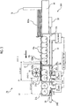
Fig. 2 is a schematic plan view illustrating an overall configuration of the corrugated fiberboard feeding apparatus according to the first embodiment of the present invention. -
Fig. 3 is a schematic sectional view illustrating the overall configuration of the corrugated fiberboard feeding apparatus according to the first embodiment of the present invention, which is seen from a side. -
Fig. 4 is a schematic view illustrating the overall configuration of the corrugated fiberboard feeding apparatus according to the first embodiment of the present invention, and is a sectional view taken along arrow A-A ofFig. 2 . -
Fig. 5 is a view for describing "a minimum length of a corrugated fiberboard" in the first embodiment of the present invention, and is a schematic side view of a slotter creaser section and a die cutting section. -
Fig. 6 is a schematic sectional view of main portions for describing operational effects of the corrugated fiberboard feeding apparatus according to the first embodiment of the present invention, which is seen from the side. -
Fig. 7 is a schematic sectional view illustrating a main portion configuration of a corrugated fiberboard feeding apparatus according to a second embodiment of the present invention, which is seen from the side. Description of Embodiments - Hereinafter, suitable embodiments of a corrugated fiberboard feeding apparatus and a box making machine of the present invention will be described in detail with reference to accompanying drawings. The present invention is not limited to the embodiments. In a case where there are a plurality of embodiments, the present invention also includes an apparatus configured by combining the respective embodiments.
- In the following description, "upstream" means an upstream side in a sheet transfer direction X, which is a transfer direction of a corrugated fiberboard, unless there is no special description otherwise, and "downstream" means a downstream side in the sheet transfer direction X unless there is no special description otherwise. In addition, hereinafter, a corrugated fiberboard width direction, which is a direction orthogonal to the sheet transfer direction X, will be referred to as a "sheet width direction W".
- First, a configuration of the box making machine including a corrugated
fiberboard feeding apparatus 24 according to the embodiment will be described in detail with reference toFig. 1 . - Each configuration of a representative box making machine and a process in which a corrugated fiberboard is processed into a sheet-like corrugated box are correlated with each other and described in
Fig. 1 . As illustrated inFig. 1 , sheet processing units including a sheet feeding section 1, aprinting section 2, a slotter creaser section 3, a die cutting section 4, a folder gluer section 5, and a counter-ejector section 6 are provided in this order from the upstream side in the box making machine. Various types of processing to be described below are performed onto the corrugated fiberboard while being transported along a horizontal sheet transport passage formed with a conveyor for transporting and a roll for transporting, from the sheet feeding section 1 to the folder gluer section 5. - In the sheet feeding section 1, the corrugated
fiberboard feeding apparatus 24 according to the first embodiment of the present invention is provided, and a plate-shapedcorrugated fiberboard 100a is placed. Thecorrugated fiberboard 100a on the lowermost layer is started to be transported in turn one by one to theprinting section 2. - For example, the
printing section 2 is formed with printing units 2a to 2d for four colors. In theprinting section 2, printing is performed in turn onto thecorrugated fiberboard 100a transported one by one by atransport conveyor belt 22 with each color of ink. - In the slotter creaser section 3, groove cutting or creasing line processing is performed onto the
corrugated fiberboard 100a printed by theprinting section 2. - In the die cutting section 4, punching processing, further groove cutting, or further creasing line processing is performed onto the
corrugated fiberboard 100a transported from the slotter creaser section 3. - In the folder gluer section 5, glue is applied to a gluing margin of one end of the
corrugated fiberboard 100a processed by the die cutting section 4 in the sheet width direction W, and folding processing is performed such that both of right and left end portions of thecorrugated fiberboard 100a are bonded on a lower side. By both of the right and left end portions being bonded to each other with glue, thecorrugated fiberboard 100a processed by the folder gluer section 5 becomes a sheet-likecorrugated box 100. - While the counter-ejector section 6 counts the number of sheet-like corrugated boxes 10 which are processed by the folder gluer section 5, the corrugated boxes are placed onto a table. After a predetermined number of
corrugated boxes 100 are stacked by the counter-ejector section 6, thissheet material group 50 is shipped as a single unit batch. - Next, the corrugated
fiberboard feeding apparatus 24 included in the sheet feeding section 1 according to the first embodiment of the present invention will be described in detail with reference toFigs. 2 to 6 . - As illustrated in
Figs. 2 to 4 , thesheet feeding apparatus 24 is configured to include anupstream transporting unit 24A and a downstream transportingunit 24B on the downstream side of the upstream transportingunit 24A. - Although a state where a
grate 16a to be described later is removed from the upstream transportingunit 24A, and a state where each ceiling surface of a box-shapeddownstream suction unit 21A and a box-shapedauxiliary suction unit 21B is removed from all parts of the downstream transportingunit 24B are illustrated inFigs. 2 and4 ,openings 16b provided in thegrate 16a andopenings 21a provided in each ceiling surface of thedownstream suction unit 21A and theauxiliary suction unit 21B are shown with chain lines inFig. 2 for convenience of description. - First, the
upstream transporting unit 24A will be described with reference toFigs. 2 and3 . - In the upstream transporting
unit 24A, thecorrugated fiberboard 100a, which is put in one by one from a transporting device (not illustrated) of the previous step, abuts against afront guide 12 and falls, and is stacked in turn onto a paper supply table 14 between abackstop 13 and the front guide as illustrated inFig. 3 . - As illustrated in
Fig. 2 , suction boxes 16N1 to 16N8 are provided along the sheet width direction W below the stackedcorrugated fiberboard 100a on the lowermost layer, and the suction boxes 16N1 to 16N8 configure anupstream suction unit 16. Theejection roller assemblies 15 are arranged in five rows along the sheet transfer direction X of thecorrugated fiberboard 100a and are rotatably accommodated in each of the suction boxes 16N1 to 16N8. - Each of the
ejection roller assemblies 15 is configured to include arotary shaft 15a extending in the sheet width direction W and a plurality ofejection rollers 15b arranged at predetermined pitches on therotary shaft 15a. Each of theejection rollers 15b protrudes to a sheet transport passage side slightly more than an upper surface of the paper supply table 14 does. Each of theejection roller assemblies 15 is provided to penetrate the plurality of suction boxes 16N1 to 16N8 arranged in the sheet width direction W. - In addition, there are
ejection roller assemblies ejection rollers 15b that are shifted away from each other, in theejection roller assemblies 15. By alternately arranging theejection roller assemblies ejection rollers 15b are in a zigzag. - Each of the
ejection roller assemblies 15 is connected to a drive motor M1 via apower transmission mechanism 15m illustrated in a simplified manner, and is intermittently rotation-driven by the drive motor M1. - The
grate 16a is provided on an upper surface of theupstream suction unit 16 as illustrated inFig. 3 . Thegrate 16a is a grid-like table having each of theopenings 16b (refer to dashed lines ofFig. 2 ) above each of theejection rollers 15b, and is driven to be risen and lowered between a raised position, which is higher than an upper edge of each of theejection rollers 15b and is shown with a two-dot chain line, and a lowered position, which is lower than the upper edge and is shown with a solid line, by a drive device (not illustrated) . Each of theejection rollers 15b is separated away from thecorrugated fiberboard 100a when thegrate 16a is at the raised position, and a part of each outer circumferential surface thereof protrudes from eachopening 16b and comes into contact with thecorrugated fiberboard 100a on the lowermost layer to eject the corrugated fiberboard when thegrate 16a is at the lowered position. - The
grate 16a repeats raising and lowering operation at appropriate timing and holds the other stacked corrugated fiberboards 100a such that only thecorrugated fiberboard 100a on the lowermost layer is adsorbed and transported one by one by the rotatingejection roller assemblies 15. -
Fig. 2 illustrates only some of theopenings 16b since the drawing becomes complicated. - An inside of the
upstream suction unit 16 is connected to asuction blower 18A via aduct 17A. Therefore, by thesuction blower 18A operating, thecorrugated fiberboard 100a on the lowermost layer is sucked downwards through theopenings 16b facing the sheet transport passage, and is drawn to theejection rollers 15b. Therefore, frictional resistance between the outer circumferential surfaces of theejection rollers 15b and a lower surface of thecorrugated fiberboard 100a acts strongly, and thus slip of theejection rollers 15b with respect to thecorrugated fiberboard 100a is suppressed. Accordingly, in response to the rotation operation of theejection rollers 15b, thecorrugated fiberboard 100a is stably transported from a gap formed in a lower end of thefront guide 12 to the downstream side (the left of the page ofFig. 2 ). - Next, the downstream transporting
unit 24B will be described. As illustrated inFigs. 2 and3 , in the downstream transportingunit 24B, thedownstream suction unit 21A is disposed on the downstream side of theupstream suction unit 16, and theauxiliary suction unit 21B is additionally disposed on the downstream side of thedownstream suction unit 21A. Thedownstream suction unit 21A is provided such that suction boxes 21AN1 to 21AN8 are arranged along the sheet width direction W, as in theupstream suction unit 16 of the upstream transportingunit 24A. - In addition, also the
auxiliary suction unit 21B is provided such that suction boxes 21BN1 to 21BN8 are arranged along the sheet width direction W, as in theupstream suction unit 16 of the upstream transportingunit 24A. - In each of the
downstream suction unit 21A and theauxiliary suction unit 21B, feedroller assemblies 11 are arranged in two rows along the sheet transfer direction X and are rotatably accommodated. - Each of the
feed roller assemblies 11 is configured to include arotary shaft 11a extending in the sheet width direction W and a plurality offeed rollers 11b arranged at predetermined pitches on therotary shaft 11a. Each of thefeed roller assemblies 11 is provided to penetrate the plurality of suction boxes 21AN1 to 21AN8 and the suction boxes 21BN1 to 21BN8, which are arranged in the sheet width direction W. - In addition, there are
feed roller assemblies feed rollers 11b that are shifted away from each other, in thefeed roller assemblies 11. By alternately arranging thefeed roller assemblies feed rollers 11b are in a zigzag. - Each of the
feed roller assemblies 11 is connected to a drive motor M2 via apower transmission mechanism 11m illustrated in a simplified manner, and is rotation-driven by the drive motor M2. - In an upper surface of each of the
downstream suction unit 21A and theauxiliary suction unit 21B, theopening 21a is formed above each of thefeed rollers 11b to face the sheet transport passage. Each of thefeed rollers 11b has an outer circumferential surface of which a part protrudes from eachopening 21a to the sheet transport passage side and comes into contact with thecorrugated fiberboard 100a to eject thecorrugated fiberboard 100a.Fig. 2 illustrates only some of theopenings 21a since the drawing becomes complicated. - In addition, pressing rolls 19 are provided above the
feed rollers 11b on the upstream side (the right of the page ofFig. 2 ) of thedownstream suction unit 21A. Each of the pressing rolls 19 is a polyurethane rotating body which includes a hollow portion and has high elasticity, and rotates with thecorrugated fiberboard 100a transported by thefeed rollers 11b. By lightly gripping thecorrugated fiberboard 100a in cooperation with thefeed rollers 11b below, the pressing rolls 19 contribute to transporting thecorrugated fiberboard 100a without crumpling. The plurality ofpressing rolls 19 are provided at an interval along the sheet width direction W. The pressing rolls 19 are omitted inFigs. 2 and4 . - An inside of the
downstream suction unit 21A and an inside of theauxiliary suction unit 21B are connected tosuction blowers ducts - Therefore, by the
suction blowers corrugated fiberboard 100a transported by theejection rollers 15b is sucked downwards through theopenings 21a, and is drawn to thefeed rollers 11b. Therefore, frictional resistance between outer circumferential surfaces of thefeed rollers 11b and the lower surface of thecorrugated fiberboard 100a acts strongly, and slip of thefeed rollers 11b with respect to thecorrugated fiberboard 100a is suppressed. Accordingly, in response to the rotation operation of thefeed rollers 11b, thecorrugated fiberboard 100a is stably transported to theprinting section 2. - The corrugated
fiberboard feeding apparatus 24 according to the first embodiment of the present invention is characteristic in that a positional relationship between theopenings 21a of thedownstream suction unit 21A and theejection rollers 15b is a particular relationship. - Specifically, as illustrated in
Figs. 2 and3 , a distance L1 between a position P1 of adownstream end 21b of thedownstream opening 21a of thedownstream suction unit 21A in the sheet transfer direction X and a position C1 of an axis CL1 of theejection roller 15b disposed on the most downstream side in the sheet transfer direction X is configured to be equal to or shorter than a minimum length Lmin of thecorrugated fiberboard 100a to be described later (L1 ≤ Lmin). - Herein, in a case where the plurality of
openings 21a are provided in thedownstream suction unit 21A along the sheet transfer direction X as in the embodiment, "the downstream end of the opening provided in the downstream suction unit in the sheet transfer direction" in the present invention means "thedownstream end 21b of theopening 21a provided on the most downstream side in the sheet transfer direction X". - In addition, the corrugated
fiberboard feeding apparatus 24 according to the first embodiment of the present invention is characteristic also in that a positional relationship between theopenings 21a of theauxiliary suction unit 21B and theopenings 21a of thedownstream suction unit 21A is a particular relationship. - Specifically, as illustrated in
Figs. 2 and3 , a distance L2 between a position P2 of thedownstream end 21b of thedownstream opening 21a of theauxiliary suction unit 21B in the sheet transfer direction X and a position C2 of an axis CL2 of thefeed roller 11b disposed on the most downstream side in thedownstream suction unit 21A in the sheet transfer direction X is configured to be equal to or shorter than the minimum length Lmin of thecorrugated fiberboard 100a to be described later (L2 ≤ Lmin). - In the embodiment, the distance L1 is set to be equal to Lmin, and the distance L2 is set to be shorter than Lmin.
- Herein, in a case where the plurality of
openings 21a are provided in theauxiliary suction unit 21B along the sheet transfer direction X as in the embodiment, "the downstream end of the opening provided in the auxiliary suction unit in the sheet transfer direction" in the present invention means "thedownstream end 21b of theopening 21a provided on the most downstream side in the sheet transfer direction X". - The "minimum length Lmin" will be described in detail with reference to
Fig. 5 . In the sheet processing units on the downstream side of the sheet feeding section 1 in the box making machine, that is, theprinting section 2, the slotter creaser section 3, the die cutting section 4, the folder gluer section 5, and the counter-ejector section 6, there is a portion where transport rolls arranged at an interval in the sheet transfer direction X perform transporting of thecorrugated fiberboard 100a. When a dimension of thecorrugated fiberboard 100a along the sheet transfer direction X is shorter than a mutual distance between the axes of the rolls, it is difficult for thecorrugated fiberboard 100a to be transferred from transport rolls on the upstream side to transport rolls on the downstream side. - That is, the transporting of a corrugated fiberboard having a dimension along the sheet transfer direction X shorter than a longest distance Dmax between the transport rolls cannot be stably performed, and the longest distance Dmax is the minimum length Lmin of the
corrugated fiberboard 100a that can be stably transported by the sheet processing units. Thus, the distances L1 and L2 are set to be equal to or shorter than the minimum length Lmin. In other words, the distances L1 and L2 each are set to a distance that is equal to or shorter than the longest distance Dmax between the transport rolls in the sheet processing units (L1 ≤ Dmax, L2 ≤ Dmax). - The transport rolls herein may each have a function of transporting the
corrugated fiberboard 100a. That is, the transport rolls are not only for transporting thecorrugated fiberboard 100a but also for executing processing onto thecorrugated fiberboard 100a while transporting thecorrugated fiberboard 100a. - In the embodiment, sections that transport the
corrugated fiberboard 100a with the transport rolls are, for example, the slotter creaser section 3 and the die cutting section 4. - As illustrated in
Fig. 5 , the slotter creaser section 3 includes a receivingroll 31a and a firstcreasing line roll 31b, a receivingroll 32a and a secondcreasing line roll 32b, a first slotterhead 33a and alower blade roll 33b, a second slotterhead 34a and alower blade roll 34b, which vertically oppose each other with the sheet transport passage sandwiched therebetween, in this order from the upstream side. - In addition, the die cutting section 4 includes feeding
pieces 41a and 41b, and ananvil cylinder 42a and aknife cylinder 42b, which vertically oppose each other with the sheet transport passage sandwiched therebetween, in this order from the upstream side. - Hereinafter, for convenience of description, the receiving
roll 31a, the firstcreasing line roll 31b, the receivingroll 32a, the secondcreasing line roll 32b, the first slotterhead 33a, thelower blade roll 33b, the second slotterhead 34a, and thelower blade roll 34b will also be referred to as the rolls. - Axes of the
upper rolls 31a to 34a, 41a, and 42a and axes of thelower rolls 31b to 34b, 41b, and 42b, which are disposed in the slotter creaser section 3 and the die cutting section 4, respectively match each other in the sheet transfer direction X, and thecorrugated fiberboard 100a is transported by being gripped by nips. - Out of distances between the nips of the
rolls 31a to 34b and 41a to 42b, that is, distances D1 to D5 between the axes of therolls 31a to 34b and 41a to 42b, the distance D3 between the first slotterhead 33a and thelower blade roll 33b and the second slotterhead 34a and thelower blade roll 34b is the longest. That is, in the embodiment, the distance D3 is the longest distance Dmax between the transport rolls, and is the minimum length Lmin of a corrugated fiberboard that can be stably transported by the box making machine. - A suction system for supplying suction power to each of the
upstream suction unit 16, thedownstream suction unit 21A, and theauxiliary suction unit 21B will be described with reference toFigs. 2 to 4 . - The suction systems of the
upstream suction unit 16, thedownstream suction unit 21A, and theauxiliary suction unit 21B are included independently of each other. Specifically, theupstream suction unit 16 is connected to thesuction blower 18A via theduct 17A, thedownstream suction unit 21A is connected to thesuction blower 18B via theduct 17B, and theauxiliary suction unit 21B is connected to thesuction blower 18C via theduct 17C. - In addition, operation, stop, and output of each of the
suction blowers control section 20. Therefore, by individually controlling output of each of thesuction blowers upstream suction unit 16, thedownstream suction unit 21A, and theauxiliary suction unit 21B. Thus, thesuction blowers control section 20 configure adjusting means of the present invention, which adjusts suction power. - For example, suction power with respect to the
upstream suction unit 16, thedownstream suction unit 21A, and theauxiliary suction unit 21B is configured to be adjustable based on a weight per unit area of the transportedcorrugated fiberboard 100a. In a case of adjusting suction power based on a weight per unit area of thecorrugated fiberboard 100a, specifically, the corrugated fiberboard is strongly pressed against thefeed rollers 11b or theejection rollers 15b due to the weight of thecorrugated fiberboard 100a as such a weight per unit area increases. Thus, suction power is set to be low with respect to theupstream suction unit 16, thedownstream suction unit 21A, and theauxiliary suction unit 21B by the pressed amount. - Since the
ducts duct 17B connected to thedownstream suction unit 21A will be mainly described. - Lower ends of the suction boxes 21AN1 to 21AN8 configuring the
downstream suction unit 21A are configured as open portions, and theduct 17B is connected thereto as a common duct. Ashutter mechanism 30 is provided in each of each open portion of the suction boxes 21AN1, 21AN2, 21AN3, 21AN6, 21AN7, and 21AN8 except for the suction boxes 21AN4 and 21AN5. Theshutter mechanism 30 includes anair cylinder 30a and theshutter member 30b attached to a drive shaft tip of theair cylinder 30a. - When the
air cylinder 30a is expanded due to such a configuration, a suction box comes into a non-use state where the open portion is blocked by theshutter member 30b and suction power from thesuction blower 18B does not act. On the other hand, when theair cylinder 30a degenerates as illustrated inFig. 3 , the suction box comes into a use state where the open portion is opened and suction power acts. The middle suction boxes 21AN4 and 21AN5 are correlated with a minimum width dimension of thecorrugated fiberboard 100a to be handled, and thus theshutter mechanism 30 is not provided as described above since the use state is caused at all times regardless of a width dimension of thecorrugated fiberboard 100a. - The
upstream suction unit 16, thedownstream suction unit 21A, and theauxiliary suction unit 21B, which are disposed to be symmetrical with respect to a center line of the sheet width direction W, are used as a pair. Since theupstream suction unit 16, thedownstream suction unit 21A, and theauxiliary suction unit 21B are configured in the same manner, thedownstream suction unit 21A will be mainly described. Specifically, the suction boxes 21AN4 and 21AN5 are used as a pair, the suction boxes 21AN3 and 21AN6 are used as a pair, the suction boxes 21AN2 and 21AN7 are used as a pair, and the suction boxes 21AN1 and 21AN8 are used as a pair. - In this case, as the width dimension of the
corrugated fiberboard 100a increases, suction boxes to become in the use state expands in turn starting from the middle suction boxes 21AN4 and 21AN5 to the outer suction boxes 21AN3 and 21AN6, the outer suction boxes 21AN2 and 21AN7, and the outer suction boxes 21AN1 and 21AN8. - In addition, suction power acts on the
openings 21a of thedownstream suction unit 21A is set to suction power acting on theopenings 16b of theupstream suction unit 16 or larger. - By configuring in such a manner, even when the
corrugated fiberboard 100a transported by the plurality ofejection rollers 15b has the minimum length Lmin as shown with hatching inFig. 3 , thecorrugated fiberboard 100a can be appropriately transported. - That is, at a time point when a trailing
end 100b of thecorrugated fiberboard 100a having the minimum length Lmin leaves the outer circumferential surface of theejection roller 15b disposed on the most downstream side and transporting power cannot be obtained from theejection rollers 15b any longer, thecorrugated fiberboard 100a completely covers theopenings 21a of thedownstream suction unit 21A from above as illustrated inFig. 3 . - At this time, although the
openings 16b of theupstream suction unit 16 are not covered with thecorrugated fiberboard 100a, theblower 18A connected to theupstream suction unit 16 and theblower 18B connected to thedownstream suction unit 21A are respectively connected to theducts downstream suction unit 21A in which theopening 21a is covered. - Therefore, since the
corrugated fiberboard 100a is reliably drawn to thefeed rollers 11b through theopenings 21a, the corrugated fiberboard receives predetermined transporting power from thefeed rollers 11b. Thus, it is possible to stably transport the corrugated fiberboard toward theprinting section 2. That is, the occurrence of slip of thefeed rollers 11b with respect to thecorrugated fiberboard 100a can be suppressed, and thecorrugated fiberboard 100a can be transported to theprinting section 2 at an appropriate position. Thus, a quality decrease, such as a shift of a printing position, can be suppressed. - On the contrary, as illustrated in
Fig. 6 , in a case where a distance L1' between thedownstream end 21b of theopening 21a and the axis CL1 of theejection roller 15b on the most downstream side, which is described above, is disposed to be longer than the minimum length Lmin of thecorrugated fiberboard 100a, thecorrugated fiberboard 100a cannot completely cover theopenings 21a from above at a time point when the trailingend 100b of thecorrugated fiberboard 100a leaves the outer circumferential surface of theejection roller 15b disposed on the most downstream side. - Therefore, since the
openings 21a of thedownstream suction unit 21A are partially open, negative pressure is not sufficient in theopenings 21a. Thus, power of drawing thecorrugated fiberboard 100a to thefeed rollers 11b is deficient, and thefeed rollers 11b slip with respect to thecorrugated fiberboard 100a. That is, thecorrugated fiberboard 100a loses transporting power from theejection rollers 15b, and sufficient transporting power cannot be obtained from thefeed rollers 11b. Thus, a quality decrease, such as a shift of a printing position, occurs without thecorrugated fiberboard 100a being transported to theprinting section 2 at an appropriate position. - In addition, since also the distance L2 between the position P2 of the
downstream end 21b of theopening 21a of theauxiliary suction unit 21B and the axis CL2 of thefeed roller 11b on the most downstream side in thedownstream suction unit 21A is configured to be equal to or shorter than the minimum length Lmin as illustrated inFigs. 2 and3 , thecorrugated fiberboard 100a can be appropriately transported even when thecorrugated fiberboard 100a has the minimum length Lmin as in thedownstream suction unit 21A. - That is, at a time point when the trailing
end 100b of thecorrugated fiberboard 100a having the minimum length Lmin leaves the outer circumferential surface of thefeed roller 11b on the most downstream side in thedownstream suction unit 21A and transporting power cannot be obtained from thefeed rollers 11b any longer, thecorrugated fiberboard 100a completely covers theopenings 21a of theauxiliary suction unit 21B from above. Thus, appropriate negative pressure works in theauxiliary suction unit 21B. - Therefore, since the
corrugated fiberboard 100a is reliably drawn to thefeed rollers 11b through theopenings 21a of theauxiliary suction unit 21B, the corrugated fiberboard receives predetermined transporting power from thefeed rollers 11b. Thus, it is possible to stably transport the corrugated fiberboard toward theprinting section 2. That is, the occurrence of slip of thefeed rollers 11b with respect to thecorrugated fiberboard 100a can be suppressed, and thecorrugated fiberboard 100a can be transported to theprinting section 2 at an appropriate position. Thus, a quality decrease, such as a shift of a printing position, can be suppressed. - In addition, since the
downstream suction unit 21A is set with the minimum length Lmin of thecorrugated fiberboard 100a as reference, suction power with respect to thecorrugated fiberboard 100a becomes insufficient and there is a possibility that sufficient transporting power cannot be obtained when transporting thecorrugated fiberboard 100a longer than the minimum length Lmin. However, the insufficiency can be complemented by providing theauxiliary suction unit 21B. - In addition, since the
pressing rolls 19 each of which includes the hollow portion and has high elasticity is provided above thefeed rollers 11b, it is possible to transport thecorrugated fiberboard 100a without crumpling by lightly gripping thecorrugated fiberboard 100a in cooperation with thefeed rollers 11b below. - Although the suction power of the upstream transporting
unit 24A has to be large enough to pull thecorrugated fiberboard 100a to theejection rollers 15b, the suction power serves as resistance when raising thegrate 16a. Thus, there is an upper limit. On the other hand, the suction power of the downstream transportingunit 24B can be set to strength that only considered pulling thecorrugated fiberboard 100a to thefeed rollers 11b. - Therefore, the suction power of the downstream transporting
unit 24B is set to power that is equal to or larger than the suction power of the upstream transportingunit 24A. Accordingly, the transporting power of thefeed rollers 11b can be reliably transmitted to thecorrugated fiberboard 100a by pulling thecorrugated fiberboard 100a to thefeed rollers 11b. Even when theejection rollers 15b slip due to insufficiency of the suction power of the upstream transportingunit 24A, thecorrugated fiberboard 100a can be appropriately transported to theprinting section 2 without thefeed rollers 11b of the downstream transportingunit 24B slipping. - Time when transporting the
corrugated fiberboard 100a having a small size can be given as an example of a case where the suction power of the downstream transportingunit 24B is made stronger than the suction power of the upstream transportingunit 24A. That is because thecorrugated fiberboard 100a is not flat in a strict sense and has a considerably small curve, and more gaps between theopenings 21a of thedownstream suction unit 21A or theauxiliary suction unit 21B and the corrugated fiberboard are generated as the size of thecorrugated fiberboard 100a decreases. In this case, since an effect of a decrease in the suction power caused by the gaps becomes noticeable, thecorrugated fiberboard 100a is reliably pulled to thefeed rollers 11b by making the suction power of the downstream transportingunit 24B strong. - In addition, since the
pressing rolls 19 are included, the flutter of thecorrugated fiberboard 100a can be suppressed by lightly gripping thecorrugated fiberboard 100a in cooperation with thefeed rollers 11b below, and thus it is possible to stably transport the corrugated fiberboard. Since each of the pressing rolls 19 includes the hollow portion and has high elasticity in particular, the crumpling of thecorrugated fiberboard 100a can be suppressed when gripping thecorrugated fiberboard 100a. - In addition, since the plurality of
feed rollers 11b are arranged in the sheet transfer direction X, the transportedcorrugated fiberboard 100a is supported by thefeed rollers 11b at a plurality of positions along the sheet transfer direction X. Therefore, the flutter of thecorrugated fiberboard 100a can be suppressed, and it is possible to stably transport thecorrugated fiberboard 100a. - Since the
feed rollers 11b are arranged in a zigzag, thecorrugated fiberboard 100a more uniformly comes into contact with thefeed rollers 11b with respect to a surface direction. Therefore, stable transporting is possible. - The
opening 21a functioning as a suction port is provided at each position of the plurality offeed rollers 11b, and a part of each of the outer circumferential surfaces of thefeed rollers 11b protrudes from theopening 21a. Therefore, compared to a case where a suction port and an opening that allows eachfeed roller 11b to protrude are separately provided, it is possible to make the size of each opening provided in each of thedownstream suction unit 21A and theauxiliary suction unit 21B to the minimum extent required, and it is possible to stabilize negative pressure inside thedownstream suction unit 21A and theauxiliary suction unit 21B. - Since the
suction blowers upstream suction unit 16, thedownstream suction unit 21A, and theauxiliary suction unit 21B independently of each other, it is possible to individually control output of each of thesuction blowers upstream suction unit 16, thedownstream suction unit 21A, and theauxiliary suction unit 21B. In addition, for example, even in a case where theupstream suction unit 16 is open without being covered with thecorrugated fiberboard 100a when transporting thecorrugated fiberboard 100a, negative pressure in thedownstream suction unit 21A can be maintained constant, and thus it is possible to stably transport thecorrugated fiberboard 100a. - Since suction power of each of the
suction blower 18A to 18C is configured to be adjustable based on a weight per unit area of the transportedcorrugated fiberboard 100a, various types of corrugated fiberboards 100a having weights per unit area different from each other can be sufficiently pulled to thefeed rollers 11b due to such suction power adjustment, and thus stable transporting is possible. - The plurality of suction boxes 16N1 to 16N8, 21AN1 to 21AN8, and 21BN1 to 21BN8 are provided along the sheet width direction W in the
upstream suction unit 16, thedownstream suction unit 21A, and theauxiliary suction unit 21B, and the supply of suction power to the suction boxes 16N1 to 16N8, 21AN1 to 21AN8, and 21BN1 to 21BN8, which are arranged in the sheet width direction W, can be controlled by theshutter members 30 according to a width dimension of thecorrugated fiberboard 100a. Therefore, out of the suction boxes 16N1 to 16N8, 21AN1 to 21AN8, and 21BN1 to 21BN8, which are provided along the sheet width direction W, a suction box to be operated can be set according to a sheet width dimension of thecorrugated fiberboard 100a without excess or insufficiency. - Next, a corrugated
fiberboard feeding apparatus 25 according to a second embodiment will be described with reference toFig. 7 . - A box making machine of the second embodiment is configured in the same manner as the first embodiment illustrated in
Figs. 1 to 6 , except for a sheet feeding section. - Reference signs in
Fig. 7 that are the same as the reference signs ofFigs. 1 to 6 , which are referred in the description of the first embodiment, indicate the same configuration elements, and detailed description thereof will be omitted. - A difference between the corrugated
fiberboard feeding apparatus 25 according to the second embodiment and the corrugatedfiberboard feeding apparatus 24 according to the first embodiment is that thefeed roller assemblies 11 accommodated in thedownstream suction unit 21A and theauxiliary suction unit 21B are in one row. - Even in this case, as in the corrugated
fiberboard feeding apparatus 24 according to the first embodiment, the corrugatedfiberboard feeding apparatus 25 is configured such that the distances L1 and L2 are equal to or shorter than the minimum length Lmin (L1 ≤ Lmin, L2 ≤ Lmin). In the embodiment, the distances L1 and L2 are set to the same dimension as the minimum length Lmin (L1 = Lmin, L2 = Lmin). - Since other configurations of the
sheet feeding apparatus 25 are the same as the configurations of thesheet feeding apparatus 24 of the first embodiment, description thereof will be omitted. - Therefore, in the corrugated
fiberboard feeding apparatus 25 according to the embodiment, the same effects as the corrugatedfiberboard feeding apparatus 24 according to the first embodiment are obtained. In addition, in a case where sufficient transporting power is obtained even when the number offeed roller assemblies 11 in thedownstream suction unit 21A and theauxiliary suction unit 21B is suppressed to one row of feed roller assemblies depending on characteristics such as a maximum weight or a basis weight of the transportedcorrugated fiberboard 100a, it is possible to reduce the number of components, thereby making the embodiment effective. - In addition, the
downstream suction unit 21A and theauxiliary suction unit 21B are likely to be miniaturized by the amount of a decrease in the number offeed roller assemblies 11 compared to the first embodiment, although the miniaturization also depends on the dimension of each of thefeed rollers 11b. Even when the minimum length Lmin is small, the distances L1 and L2 are likely to be set to the minimum length Lmin or shorter. - Although the embodiments of the present invention are described hereinbefore, the present invention is not limited to each of the embodiments described above, and can be executed after making appropriate modification, omission, or combination without departing from the spirit of the present invention.
- (1) It is also possible to press the transported
corrugated fiberboard 100a by adopting, for example, a spring plate or an air blow instead of the pressing rolls 19. - (2) In addition, in each of the embodiments, suction power acting on the
upstream suction unit 16, thedownstream suction unit 21A, and theauxiliary suction unit 21B is adjusted by thecontrol section 20 controlling the output of thesuction blowers ducts suction blowers upstream suction unit 16, thedownstream suction unit 21A, and theauxiliary suction unit 21B. By adjusting opening degrees of the dampers in accordance with a command from thecontrol section 20 or manual operation of an operator, suction power acting on theupstream suction unit 16, thedownstream suction unit 21A, and theauxiliary suction unit 21B may be adjusted. In a case where thecontrol section 20 controls the opening degrees of the dampers, the dampers and thecontrol section 20 configure the adjusting means of the present invention, which adjusts suction power. In a case where an operator manually adjusts the dampers, the dampers configure the adjusting means of the present invention, which adjusts suction power. - (3) Although two units including the
downstream suction unit 21A and theauxiliary suction unit 21B are provided in the downstream transportingunit 24B in each of the embodiments, only one suction unit may be provided, or three or more suction units may be provided in the downstream transportingunit 24B. - (4) Although the
openings 21a that allow thefeed rollers 11b to protrude are also used as suction ports through which suction power acts on thecorrugated fiberboard 100a in each of the embodiments, suction ports may be provided separately from theopenings 21a. -
- 1: sheet feeding section (sheet processing unit)
- 2: printing section (sheet processing unit)
- 3: slotter creaser section (sheet processing unit)
- 4: die cutting section (sheet processing unit)
- 5: folder gluer section (sheet processing unit)
- 6: counter-ejector section (sheet processing unit)
- 11b: feed roller
- 12: front guide
- 13: backstop
- 14: paper supply table
- 15: ejection roller assembly
- 15a: rotary shaft
- 15b: ejection roller
- 16: upstream suction unit
- 16N1 to 16N8, 21AN1 to 21AN8, 21BN1 to 21BN8: suction box
- 16a: grate
- 16b: opening
- 17A, 17B, 17C: duct
- 18A, 18B, 18C: suction blower
- 19: pressing roll
- 20: control section
- 21A: downstream suction unit
- 21B: auxiliary suction unit
- 21a: opening
- 21b: downstream end of
opening 21a - 22: transport conveyor belt
- 24, 25: corrugated fiberboard feeding apparatus
- 30: shutter mechanism
- 30a: air cylinder
- 30b: shutter member
- 100: corrugated box
- 100a: corrugated fiberboard
- CL1, CL2: axis of
ejection roller 15b - L1: distance between
downstream end 21b ofopening 21a and axis CL1 ofejection roller 15b - L2: distance between
downstream end 21b ofopening 21a and axis CL2 offeed roller 11b - Lmin: minimum length of corrugated fiberboard
Claims (13)
- A corrugated fiberboard feeding apparatus comprising:an upstream transporting unit that has a plurality of ejection rollers which eject a corrugated fiberboard placed on upper surfaces thereof, and transports the corrugated fiberboard placed on the ejection rollers; anda downstream transporting unit that is adjacent to a downstream side in a sheet transfer direction with respect to the upstream transporting unit and transports the corrugated fiberboard ejected from the upstream transporting unit to a sheet processing unit on the downstream side,wherein the downstream transporting unit hasa downstream suction unit that has an opening facing a sheet transport passage, anda feed roller that is accommodated in the downstream suction unit and has an outer circumferential surface of which a part protrudes to a sheet transport passage side, anda distance in the sheet transfer direction between a downstream end of the opening in the sheet transfer direction and an axis of the ejection roller on the most downstream side in the sheet transfer direction, out of the plurality of ejection rollers, is set to a maximum distance of a mutual distance between a plurality of transport rollers of the sheet processing unit, which transport the corrugated fiberboard, or shorter.
- The corrugated fiberboard feeding apparatus according to Claim 1,
wherein the downstream transporting unit further has, above the feed roller, a pressing mechanism that regulates an upper surface of the ejected corrugated fiberboard. - The corrugated fiberboard feeding apparatus according to Claim 2,
wherein the pressing mechanism is a pressing roll that comes into contact with the upper surface of the corrugated fiberboard which is being transported, is rotatably provided, and includes a hollow portion. - The corrugated fiberboard feeding apparatus according to any one of Claims 1 to 3,
wherein a plurality of the feed rollers are arranged in the sheet transfer direction. - The corrugated fiberboard feeding apparatus according to Claim 4,
wherein the plurality of the feed rollers are further arranged along a sheet width direction orthogonal to the sheet transfer direction and are arranged in a zigzag. - The corrugated fiberboard feeding apparatus according to any one of Claims 1 to 5,
wherein a plurality of the feed rollers are provided,
the opening is provided at each position of the plurality of the feed rollers, and
each of the feed rollers has the outer circumferential surface of which a part protrudes from the opening. - The corrugated fiberboard feeding apparatus according to any one of Claims 1 to 6,
wherein the downstream transporting unit hasan auxiliary suction unit that is disposed on the downstream side of the downstream suction unit and has an opening facing the sheet transport passage, anda feed roller that is accommodated in the auxiliary suction unit and has an outer circumferential surface of which a part protrudes to the sheet transport passage. - The corrugated fiberboard feeding apparatus according to Claim 7, further comprising:an upstream suction unit on an upstream side of the downstream suction unit,wherein the upstream suction unit, the downstream suction unit, and the auxiliary suction unit are each independently connected with a suction blower.
- The corrugated fiberboard feeding apparatus according to Claim 7 or 8, further comprising:an upstream suction unit on an upstream side of the downstream suction unit,wherein adjusting means for adjusting suction power is included in each of the upstream suction unit, the downstream suction unit, and the auxiliary suction unit.
- The corrugated fiberboard feeding apparatus according to Claim 8 or Claim 9 citing Claim 8,
wherein suction power of each of the suction blowers is configured to be adjustable based on a weight per unit area of the transported corrugated fiberboard. - The corrugated fiberboard feeding apparatus according to any one of Claim 8, Claim 9 citing Claim 8, and Claim 10, further comprising:an upstream suction unit on an upstream side of the downstream suction unit,wherein a plurality of suction boxes are provided, along a sheet width direction orthogonal to the sheet transfer direction, in at least one suction unit of the upstream suction unit, the downstream suction unit, and the auxiliary suction unit, andin each passage that connects the plurality of suction boxes to the suction blowers, a shutter member that opens and closes the passage is included.
- The corrugated fiberboard feeding apparatus according to any one of Claim 8, Claim 9 citing Claim 8, Claim 10, and Claim 11,
wherein the upstream transporting unit includesa grate that separates the corrugated fiberboard on the lowermost layer away from the plurality of ejection rollers at a raised position higher than a height of each of upper edges of the plurality of ejection rollers, and brings the corrugated fiberboard on the lowermost layer into contact with the ejection rollers at a lowered position lower than the height of each of the upper edges, anda drive device that drives the grate to raise and lower the grate between the raised position and the lowered position,adjusting means for adjusting suction power is included in each of the upstream suction unit and the downstream suction unit, andthe adjusting means sets at least the suction power of the downstream suction unit to the suction power of the upstream suction unit or larger. - A box making machine comprising:a sheet feeding section that feeds a corrugated fiberboard one by one;a printing section that prints the corrugated fiberboard fed from the sheet feeding section;a slotter creaser section that performs groove cutting and creasing line processing onto the corrugated fiberboard printed by the printing section;a die cutting section that performs punching processing onto the corrugated fiberboard on which the groove cutting and the creasing line processing are performed;a folder gluer section that applies glue to an end portion of the corrugated fiberboard processed by the die cutting section and performs folding processing to form a sheet-like corrugated box; anda counter-ejector section that stacks the corrugated box processed by the folder gluer section while counting the number of the corrugated box,wherein the corrugated fiberboard feeding apparatus according to any one of Claims 1 to 12 is provided in the sheet feeding section.
Applications Claiming Priority (2)
| Application Number | Priority Date | Filing Date | Title |
|---|---|---|---|
| JP2017023229A JP6805016B2 (en) | 2017-02-10 | 2017-02-10 | Corrugated cardboard sheet feeding device and box making machine |
| PCT/JP2018/004304 WO2018147350A1 (en) | 2017-02-10 | 2018-02-08 | Corrugated cardboard sheet feeding apparatus and box making machine |
Publications (3)
| Publication Number | Publication Date |
|---|---|
| EP3556693A1 true EP3556693A1 (en) | 2019-10-23 |
| EP3556693A4 EP3556693A4 (en) | 2020-01-22 |
| EP3556693B1 EP3556693B1 (en) | 2021-06-30 |
Family
ID=63107585
Family Applications (1)
| Application Number | Title | Priority Date | Filing Date |
|---|---|---|---|
| EP18751796.6A Active EP3556693B1 (en) | 2017-02-10 | 2018-02-08 | Corrugated cardboard sheet feeding apparatus and box making machine |
Country Status (6)
| Country | Link |
|---|---|
| US (1) | US20200023603A1 (en) |
| EP (1) | EP3556693B1 (en) |
| JP (1) | JP6805016B2 (en) |
| KR (1) | KR20190103312A (en) |
| CN (1) | CN110198905B (en) |
| WO (1) | WO2018147350A1 (en) |
Cited By (1)
| Publication number | Priority date | Publication date | Assignee | Title |
|---|---|---|---|---|
| WO2024246023A1 (en) * | 2023-06-02 | 2024-12-05 | Bobst Lyon | Feeder module for a converting machine |
Families Citing this family (10)
| Publication number | Priority date | Publication date | Assignee | Title |
|---|---|---|---|---|
| JP7296977B2 (en) * | 2018-02-26 | 2023-06-23 | サン オートメーション インク. | Sheet feeder improvement apparatus and method for corrugated board or cardboard board without feed roll |
| US11584010B2 (en) | 2018-12-19 | 2023-02-21 | Pearson Packaging Systems | Knocked-down case inspection and erection method |
| CN110356098A (en) * | 2019-07-09 | 2019-10-22 | 广东拓品智能机械科技有限公司 | A kind of printing ceramics wheel |
| US11325799B2 (en) * | 2019-09-13 | 2022-05-10 | Xerox Corporation | Interdigitated vacuum roll system for a cut sheet printer dryer transport |
| CN111572097A (en) * | 2020-06-11 | 2020-08-25 | 深圳市科发机械制造有限公司 | Synchronous belt transmission structure and processing equipment |
| CN112406174B (en) * | 2020-11-11 | 2022-11-01 | 苏州市相城区永浩纸业有限公司 | Automatic production line for corrugated cartons |
| JP7187055B2 (en) * | 2021-02-22 | 2022-12-12 | 株式会社上田紙工機 | sheet conveying device |
| CN113246535B (en) * | 2021-04-01 | 2022-11-22 | 宁波中和包装科技有限公司 | Inkless printing process for carton |
| CN117002079B (en) * | 2022-11-07 | 2025-10-14 | 青岛澳派智能包装有限公司 | Paper changer and carton processing machine |
| CN116374681B (en) * | 2023-04-23 | 2025-06-13 | 常州汉威信科技股份有限公司 | Multi-link paper roller assembly component, multi-link paper roller assembly device and working method thereof |
Family Cites Families (20)
| Publication number | Priority date | Publication date | Assignee | Title |
|---|---|---|---|---|
| US3861669A (en) * | 1972-06-15 | 1975-01-21 | Tokyo Shibaura Electric Co | Apparatus for feeding sheet-like articles from a stack of articles |
| JPS6064932U (en) * | 1983-10-13 | 1985-05-08 | 株式会社リコー | Automatic document feeder |
| US5531432A (en) * | 1988-10-13 | 1996-07-02 | Sardella; Louis M. | Method and apparatus for feeding sheets |
| US5074539A (en) | 1990-09-11 | 1991-12-24 | Ward Holding Company, Inc. | Feeding sheets of corrugated paperboard |
| JP2887041B2 (en) * | 1993-03-12 | 1999-04-26 | 株式会社タクミ精工 | Paper feeder |
| JPH0768835A (en) * | 1993-09-06 | 1995-03-14 | Canon Inc | Image forming device |
| EP0773177A3 (en) * | 1995-11-08 | 1997-10-29 | Martin Family Trust | Vacuum conveyor |
| JP3782506B2 (en) * | 1996-04-30 | 2006-06-07 | 三菱重工業株式会社 | Paperboard feeder |
| DE19724733C2 (en) * | 1997-06-12 | 2001-10-04 | Roland Man Druckmasch | Sheet feeder |
| JPH11314785A (en) * | 1998-05-07 | 1999-11-16 | Mitsubishi Heavy Ind Ltd | Paper feeder for corrugated sheet |
| KR20070067897A (en) * | 2005-12-26 | 2007-06-29 | 씨앤에스 (주) | Punching Machine Automatic Feeding Device |
| JP4858587B2 (en) * | 2009-08-31 | 2012-01-18 | ブラザー工業株式会社 | Recording device |
| JP5342495B2 (en) * | 2010-04-15 | 2013-11-13 | 株式会社梅谷製作所 | Corrugated sheet printing machine |
| CN101935959B (en) * | 2010-08-09 | 2012-12-05 | 青岛美光机械有限公司 | Servo side pressing and paper feeding machine |
| CN202321704U (en) * | 2011-12-09 | 2012-07-11 | 福州兆科智能卡有限公司 | Automatic card arranging device for personalized cards |
| EP2639190B1 (en) * | 2012-03-16 | 2017-07-19 | Kabushiki Kaisha Toshiba | Sheet-handling apparatus |
| JP2014156322A (en) * | 2013-02-15 | 2014-08-28 | Mitsubishi Heavy Ind Ltd | Vibration suppression device for rotary guide, sheet feeding device having the vibration suppression device for rotary guide, and carton former having the sheet feeding device |
| CN204021995U (en) * | 2014-05-08 | 2014-12-17 | 江阴比图特种纸板有限公司 | A kind of cardboard automatic feeding machine |
| JP6106644B2 (en) * | 2014-08-29 | 2017-04-05 | 昌弘 塚崎 | Paper feeder |
| US9522798B2 (en) * | 2015-04-30 | 2016-12-20 | Theodore Michael Baum | Corrugated paperboard box converting machine retrofit for eliminating edge crush test degradation |
-
2017
- 2017-02-10 JP JP2017023229A patent/JP6805016B2/en active Active
-
2018
- 2018-02-08 CN CN201880007304.7A patent/CN110198905B/en active Active
- 2018-02-08 EP EP18751796.6A patent/EP3556693B1/en active Active
- 2018-02-08 US US16/484,847 patent/US20200023603A1/en not_active Abandoned
- 2018-02-08 WO PCT/JP2018/004304 patent/WO2018147350A1/en not_active Ceased
- 2018-02-08 KR KR1020197022950A patent/KR20190103312A/en not_active Ceased
Cited By (1)
| Publication number | Priority date | Publication date | Assignee | Title |
|---|---|---|---|---|
| WO2024246023A1 (en) * | 2023-06-02 | 2024-12-05 | Bobst Lyon | Feeder module for a converting machine |
Also Published As
| Publication number | Publication date |
|---|---|
| WO2018147350A1 (en) | 2018-08-16 |
| US20200023603A1 (en) | 2020-01-23 |
| EP3556693A4 (en) | 2020-01-22 |
| KR20190103312A (en) | 2019-09-04 |
| JP6805016B2 (en) | 2020-12-23 |
| EP3556693B1 (en) | 2021-06-30 |
| CN110198905A (en) | 2019-09-03 |
| CN110198905B (en) | 2021-02-26 |
| JP2018127351A (en) | 2018-08-16 |
Similar Documents
| Publication | Publication Date | Title |
|---|---|---|
| EP3556693B1 (en) | Corrugated cardboard sheet feeding apparatus and box making machine | |
| CN109195784B (en) | Cardboard folding device and box making machine | |
| US5163891A (en) | Box forming machine having a vacuum belt top conveyor | |
| US10800061B2 (en) | Slotter device, sheet slicing method, and carton former | |
| US9833963B2 (en) | Sheet folding device and carton former | |
| JPH04223951A (en) | Carrying table to guide printing sheet paper to printing machine | |
| JPH0155172B2 (en) | ||
| JPH07285703A (en) | Method and device to feed leaf paper to be printed to press under partially overlapped condition | |
| US11890829B2 (en) | Cardboard box dividing device and cardboard box production device | |
| WO2017043103A1 (en) | Sheet stacking device, counter ejector and box making machine | |
| US8157261B2 (en) | Paper sheet conveying device and paper sheet conveying system | |
| JP6873260B2 (en) | Sheet folding device and box making machine | |
| US8960663B2 (en) | Sheet feeder with two suction wheels | |
| JP2009249152A (en) | Sheet-like work delivery method and delivery device | |
| CN101516751A (en) | Auxiliary drive for conveying sheets on the feed table of a die-cutting press | |
| JPH11156796A (en) | Sheet material punching method and apparatus | |
| JP3581529B2 (en) | Sheet transport device for printing section | |
| JPH09194058A (en) | Bottom feeder | |
| JP4247141B2 (en) | Sheet conveying device for printing section | |
| JP3920159B2 (en) | Theta for printing press | |
| JP7040768B2 (en) | Paper cutting and discharging device | |
| JP7355540B2 (en) | Saddle stitcher for printed products | |
| CN105293120A (en) | Feeder head for paper feeding mechanism and paper feeding method of feeder head | |
| JPH11314785A (en) | Paper feeder for corrugated sheet | |
| JP2015157690A (en) | Sheet folding system and sheet folding method |
Legal Events
| Date | Code | Title | Description |
|---|---|---|---|
| STAA | Information on the status of an ep patent application or granted ep patent |
Free format text: STATUS: THE INTERNATIONAL PUBLICATION HAS BEEN MADE |
|
| PUAI | Public reference made under article 153(3) epc to a published international application that has entered the european phase |
Free format text: ORIGINAL CODE: 0009012 |
|
| STAA | Information on the status of an ep patent application or granted ep patent |
Free format text: STATUS: REQUEST FOR EXAMINATION WAS MADE |
|
| 17P | Request for examination filed |
Effective date: 20190719 |
|
| AK | Designated contracting states |
Kind code of ref document: A1 Designated state(s): AL AT BE BG CH CY CZ DE DK EE ES FI FR GB GR HR HU IE IS IT LI LT LU LV MC MK MT NL NO PL PT RO RS SE SI SK SM TR |
|
| AX | Request for extension of the european patent |
Extension state: BA ME |
|
| A4 | Supplementary search report drawn up and despatched |
Effective date: 20200107 |
|
| RIC1 | Information provided on ipc code assigned before grant |
Ipc: B65H 5/06 20060101ALI20191219BHEP Ipc: B65H 3/06 20060101ALI20191219BHEP Ipc: B65H 3/12 20060101AFI20191219BHEP Ipc: B65H 1/06 20060101ALI20191219BHEP Ipc: B65H 3/56 20060101ALI20191219BHEP |
|
| DAV | Request for validation of the european patent (deleted) | ||
| DAX | Request for extension of the european patent (deleted) | ||
| GRAP | Despatch of communication of intention to grant a patent |
Free format text: ORIGINAL CODE: EPIDOSNIGR1 |
|
| STAA | Information on the status of an ep patent application or granted ep patent |
Free format text: STATUS: GRANT OF PATENT IS INTENDED |
|
| INTG | Intention to grant announced |
Effective date: 20210219 |
|
| GRAS | Grant fee paid |
Free format text: ORIGINAL CODE: EPIDOSNIGR3 |
|
| GRAA | (expected) grant |
Free format text: ORIGINAL CODE: 0009210 |
|
| STAA | Information on the status of an ep patent application or granted ep patent |
Free format text: STATUS: THE PATENT HAS BEEN GRANTED |
|
| AK | Designated contracting states |
Kind code of ref document: B1 Designated state(s): AL AT BE BG CH CY CZ DE DK EE ES FI FR GB GR HR HU IE IS IT LI LT LU LV MC MK MT NL NO PL PT RO RS SE SI SK SM TR |
|
| REG | Reference to a national code |
Ref country code: CH Ref legal event code: EP |
|
| REG | Reference to a national code |
Ref country code: DE Ref legal event code: R096 Ref document number: 602018019432 Country of ref document: DE Ref country code: AT Ref legal event code: REF Ref document number: 1406192 Country of ref document: AT Kind code of ref document: T Effective date: 20210715 |
|
| REG | Reference to a national code |
Ref country code: IE Ref legal event code: FG4D |
|
| REG | Reference to a national code |
Ref country code: SE Ref legal event code: TRGR |
|
| REG | Reference to a national code |
Ref country code: LT Ref legal event code: MG9D |
|
| PG25 | Lapsed in a contracting state [announced via postgrant information from national office to epo] |
Ref country code: BG Free format text: LAPSE BECAUSE OF FAILURE TO SUBMIT A TRANSLATION OF THE DESCRIPTION OR TO PAY THE FEE WITHIN THE PRESCRIBED TIME-LIMIT Effective date: 20210930 Ref country code: HR Free format text: LAPSE BECAUSE OF FAILURE TO SUBMIT A TRANSLATION OF THE DESCRIPTION OR TO PAY THE FEE WITHIN THE PRESCRIBED TIME-LIMIT Effective date: 20210630 Ref country code: FI Free format text: LAPSE BECAUSE OF FAILURE TO SUBMIT A TRANSLATION OF THE DESCRIPTION OR TO PAY THE FEE WITHIN THE PRESCRIBED TIME-LIMIT Effective date: 20210630 |
|
| REG | Reference to a national code |
Ref country code: NL Ref legal event code: MP Effective date: 20210630 |
|
| REG | Reference to a national code |
Ref country code: AT Ref legal event code: MK05 Ref document number: 1406192 Country of ref document: AT Kind code of ref document: T Effective date: 20210630 |
|
| PG25 | Lapsed in a contracting state [announced via postgrant information from national office to epo] |
Ref country code: RS Free format text: LAPSE BECAUSE OF FAILURE TO SUBMIT A TRANSLATION OF THE DESCRIPTION OR TO PAY THE FEE WITHIN THE PRESCRIBED TIME-LIMIT Effective date: 20210630 Ref country code: LV Free format text: LAPSE BECAUSE OF FAILURE TO SUBMIT A TRANSLATION OF THE DESCRIPTION OR TO PAY THE FEE WITHIN THE PRESCRIBED TIME-LIMIT Effective date: 20210630 Ref country code: NO Free format text: LAPSE BECAUSE OF FAILURE TO SUBMIT A TRANSLATION OF THE DESCRIPTION OR TO PAY THE FEE WITHIN THE PRESCRIBED TIME-LIMIT Effective date: 20210930 Ref country code: GR Free format text: LAPSE BECAUSE OF FAILURE TO SUBMIT A TRANSLATION OF THE DESCRIPTION OR TO PAY THE FEE WITHIN THE PRESCRIBED TIME-LIMIT Effective date: 20211001 |
|
| PG25 | Lapsed in a contracting state [announced via postgrant information from national office to epo] |
Ref country code: ES Free format text: LAPSE BECAUSE OF FAILURE TO SUBMIT A TRANSLATION OF THE DESCRIPTION OR TO PAY THE FEE WITHIN THE PRESCRIBED TIME-LIMIT Effective date: 20210630 Ref country code: EE Free format text: LAPSE BECAUSE OF FAILURE TO SUBMIT A TRANSLATION OF THE DESCRIPTION OR TO PAY THE FEE WITHIN THE PRESCRIBED TIME-LIMIT Effective date: 20210630 Ref country code: SK Free format text: LAPSE BECAUSE OF FAILURE TO SUBMIT A TRANSLATION OF THE DESCRIPTION OR TO PAY THE FEE WITHIN THE PRESCRIBED TIME-LIMIT Effective date: 20210630 Ref country code: CZ Free format text: LAPSE BECAUSE OF FAILURE TO SUBMIT A TRANSLATION OF THE DESCRIPTION OR TO PAY THE FEE WITHIN THE PRESCRIBED TIME-LIMIT Effective date: 20210630 Ref country code: AT Free format text: LAPSE BECAUSE OF FAILURE TO SUBMIT A TRANSLATION OF THE DESCRIPTION OR TO PAY THE FEE WITHIN THE PRESCRIBED TIME-LIMIT Effective date: 20210630 Ref country code: SM Free format text: LAPSE BECAUSE OF FAILURE TO SUBMIT A TRANSLATION OF THE DESCRIPTION OR TO PAY THE FEE WITHIN THE PRESCRIBED TIME-LIMIT Effective date: 20210630 Ref country code: RO Free format text: LAPSE BECAUSE OF FAILURE TO SUBMIT A TRANSLATION OF THE DESCRIPTION OR TO PAY THE FEE WITHIN THE PRESCRIBED TIME-LIMIT Effective date: 20210630 Ref country code: PT Free format text: LAPSE BECAUSE OF FAILURE TO SUBMIT A TRANSLATION OF THE DESCRIPTION OR TO PAY THE FEE WITHIN THE PRESCRIBED TIME-LIMIT Effective date: 20211102 Ref country code: NL Free format text: LAPSE BECAUSE OF FAILURE TO SUBMIT A TRANSLATION OF THE DESCRIPTION OR TO PAY THE FEE WITHIN THE PRESCRIBED TIME-LIMIT Effective date: 20210630 |
|
| PG25 | Lapsed in a contracting state [announced via postgrant information from national office to epo] |
Ref country code: PL Free format text: LAPSE BECAUSE OF FAILURE TO SUBMIT A TRANSLATION OF THE DESCRIPTION OR TO PAY THE FEE WITHIN THE PRESCRIBED TIME-LIMIT Effective date: 20210630 |
|
| REG | Reference to a national code |
Ref country code: DE Ref legal event code: R097 Ref document number: 602018019432 Country of ref document: DE |
|
| PG25 | Lapsed in a contracting state [announced via postgrant information from national office to epo] |
Ref country code: DK Free format text: LAPSE BECAUSE OF FAILURE TO SUBMIT A TRANSLATION OF THE DESCRIPTION OR TO PAY THE FEE WITHIN THE PRESCRIBED TIME-LIMIT Effective date: 20210630 |
|
| PLBE | No opposition filed within time limit |
Free format text: ORIGINAL CODE: 0009261 |
|
| STAA | Information on the status of an ep patent application or granted ep patent |
Free format text: STATUS: NO OPPOSITION FILED WITHIN TIME LIMIT |
|
| PG25 | Lapsed in a contracting state [announced via postgrant information from national office to epo] |
Ref country code: AL Free format text: LAPSE BECAUSE OF FAILURE TO SUBMIT A TRANSLATION OF THE DESCRIPTION OR TO PAY THE FEE WITHIN THE PRESCRIBED TIME-LIMIT Effective date: 20210630 |
|
| 26N | No opposition filed |
Effective date: 20220331 |
|
| PG25 | Lapsed in a contracting state [announced via postgrant information from national office to epo] |
Ref country code: IT Free format text: LAPSE BECAUSE OF FAILURE TO SUBMIT A TRANSLATION OF THE DESCRIPTION OR TO PAY THE FEE WITHIN THE PRESCRIBED TIME-LIMIT Effective date: 20210630 |
|
| REG | Reference to a national code |
Ref country code: DE Ref legal event code: R119 Ref document number: 602018019432 Country of ref document: DE |
|
| PG25 | Lapsed in a contracting state [announced via postgrant information from national office to epo] |
Ref country code: MC Free format text: LAPSE BECAUSE OF FAILURE TO SUBMIT A TRANSLATION OF THE DESCRIPTION OR TO PAY THE FEE WITHIN THE PRESCRIBED TIME-LIMIT Effective date: 20210630 |
|
| REG | Reference to a national code |
Ref country code: CH Ref legal event code: PL |
|
| REG | Reference to a national code |
Ref country code: BE Ref legal event code: MM Effective date: 20220228 |
|
| GBPC | Gb: european patent ceased through non-payment of renewal fee |
Effective date: 20220208 |
|
| PG25 | Lapsed in a contracting state [announced via postgrant information from national office to epo] |
Ref country code: LU Free format text: LAPSE BECAUSE OF NON-PAYMENT OF DUE FEES Effective date: 20220208 |
|
| PG25 | Lapsed in a contracting state [announced via postgrant information from national office to epo] |
Ref country code: LI Free format text: LAPSE BECAUSE OF NON-PAYMENT OF DUE FEES Effective date: 20220228 Ref country code: IE Free format text: LAPSE BECAUSE OF NON-PAYMENT OF DUE FEES Effective date: 20220208 Ref country code: GB Free format text: LAPSE BECAUSE OF NON-PAYMENT OF DUE FEES Effective date: 20220208 Ref country code: DE Free format text: LAPSE BECAUSE OF NON-PAYMENT OF DUE FEES Effective date: 20220901 Ref country code: CH Free format text: LAPSE BECAUSE OF NON-PAYMENT OF DUE FEES Effective date: 20220228 |
|
| PG25 | Lapsed in a contracting state [announced via postgrant information from national office to epo] |
Ref country code: BE Free format text: LAPSE BECAUSE OF NON-PAYMENT OF DUE FEES Effective date: 20220228 |
|
| PG25 | Lapsed in a contracting state [announced via postgrant information from national office to epo] |
Ref country code: LT Free format text: LAPSE BECAUSE OF FAILURE TO SUBMIT A TRANSLATION OF THE DESCRIPTION OR TO PAY THE FEE WITHIN THE PRESCRIBED TIME-LIMIT Effective date: 20210630 |
|
| PG25 | Lapsed in a contracting state [announced via postgrant information from national office to epo] |
Ref country code: MK Free format text: LAPSE BECAUSE OF FAILURE TO SUBMIT A TRANSLATION OF THE DESCRIPTION OR TO PAY THE FEE WITHIN THE PRESCRIBED TIME-LIMIT Effective date: 20210630 Ref country code: CY Free format text: LAPSE BECAUSE OF FAILURE TO SUBMIT A TRANSLATION OF THE DESCRIPTION OR TO PAY THE FEE WITHIN THE PRESCRIBED TIME-LIMIT Effective date: 20210630 |
|
| PG25 | Lapsed in a contracting state [announced via postgrant information from national office to epo] |
Ref country code: HU Free format text: LAPSE BECAUSE OF FAILURE TO SUBMIT A TRANSLATION OF THE DESCRIPTION OR TO PAY THE FEE WITHIN THE PRESCRIBED TIME-LIMIT; INVALID AB INITIO Effective date: 20180208 |
|
| PG25 | Lapsed in a contracting state [announced via postgrant information from national office to epo] |
Ref country code: MT Free format text: LAPSE BECAUSE OF FAILURE TO SUBMIT A TRANSLATION OF THE DESCRIPTION OR TO PAY THE FEE WITHIN THE PRESCRIBED TIME-LIMIT Effective date: 20210630 |
|
| PG25 | Lapsed in a contracting state [announced via postgrant information from national office to epo] |
Ref country code: TR Free format text: LAPSE BECAUSE OF FAILURE TO SUBMIT A TRANSLATION OF THE DESCRIPTION OR TO PAY THE FEE WITHIN THE PRESCRIBED TIME-LIMIT Effective date: 20210630 |
|
| PGFP | Annual fee paid to national office [announced via postgrant information from national office to epo] |
Ref country code: FR Payment date: 20251231 Year of fee payment: 9 |
|
| PGFP | Annual fee paid to national office [announced via postgrant information from national office to epo] |
Ref country code: SE Payment date: 20251230 Year of fee payment: 9 |