EP3556654A1 - Nutzlasteingriffssysteme, fahrzeuge damit und zugehörige verfahren - Google Patents
Nutzlasteingriffssysteme, fahrzeuge damit und zugehörige verfahren Download PDFInfo
- Publication number
- EP3556654A1 EP3556654A1 EP19165955.6A EP19165955A EP3556654A1 EP 3556654 A1 EP3556654 A1 EP 3556654A1 EP 19165955 A EP19165955 A EP 19165955A EP 3556654 A1 EP3556654 A1 EP 3556654A1
- Authority
- EP
- European Patent Office
- Prior art keywords
- payload
- engagement system
- receptor
- vehicle
- insert
- Prior art date
- Legal status (The legal status is an assumption and is not a legal conclusion. Google has not performed a legal analysis and makes no representation as to the accuracy of the status listed.)
- Granted
Links
Images


Classifications
-
- B—PERFORMING OPERATIONS; TRANSPORTING
- B64—AIRCRAFT; AVIATION; COSMONAUTICS
- B64D—EQUIPMENT FOR FITTING IN OR TO AIRCRAFT; FLIGHT SUITS; PARACHUTES; ARRANGEMENT OR MOUNTING OF POWER PLANTS OR PROPULSION TRANSMISSIONS IN AIRCRAFT
- B64D1/00—Dropping, ejecting, releasing or receiving articles, liquids, or the like, in flight
- B64D1/02—Dropping, ejecting, or releasing articles
- B64D1/08—Dropping, ejecting, or releasing articles the articles being load-carrying devices
- B64D1/12—Releasing
-
- B—PERFORMING OPERATIONS; TRANSPORTING
- B64—AIRCRAFT; AVIATION; COSMONAUTICS
- B64D—EQUIPMENT FOR FITTING IN OR TO AIRCRAFT; FLIGHT SUITS; PARACHUTES; ARRANGEMENT OR MOUNTING OF POWER PLANTS OR PROPULSION TRANSMISSIONS IN AIRCRAFT
- B64D9/00—Equipment for handling freight; Equipment for facilitating passenger embarkation or the like
-
- B—PERFORMING OPERATIONS; TRANSPORTING
- B64—AIRCRAFT; AVIATION; COSMONAUTICS
- B64D—EQUIPMENT FOR FITTING IN OR TO AIRCRAFT; FLIGHT SUITS; PARACHUTES; ARRANGEMENT OR MOUNTING OF POWER PLANTS OR PROPULSION TRANSMISSIONS IN AIRCRAFT
- B64D1/00—Dropping, ejecting, releasing or receiving articles, liquids, or the like, in flight
- B64D1/22—Taking-up articles from earth's surface
-
- B—PERFORMING OPERATIONS; TRANSPORTING
- B64—AIRCRAFT; AVIATION; COSMONAUTICS
- B64U—UNMANNED AERIAL VEHICLES [UAV]; EQUIPMENT THEREFOR
- B64U10/00—Type of UAV
- B64U10/10—Rotorcrafts
- B64U10/13—Flying platforms
-
- B—PERFORMING OPERATIONS; TRANSPORTING
- B64—AIRCRAFT; AVIATION; COSMONAUTICS
- B64U—UNMANNED AERIAL VEHICLES [UAV]; EQUIPMENT THEREFOR
- B64U2101/00—UAVs specially adapted for particular uses or applications
- B64U2101/60—UAVs specially adapted for particular uses or applications for transporting passengers; for transporting goods other than weapons
- B64U2101/64—UAVs specially adapted for particular uses or applications for transporting passengers; for transporting goods other than weapons for parcel delivery or retrieval
-
- B—PERFORMING OPERATIONS; TRANSPORTING
- B64—AIRCRAFT; AVIATION; COSMONAUTICS
- B64U—UNMANNED AERIAL VEHICLES [UAV]; EQUIPMENT THEREFOR
- B64U2201/00—UAVs characterised by their flight controls
- B64U2201/10—UAVs characterised by their flight controls autonomous, i.e. by navigating independently from ground or air stations, e.g. by using inertial navigation systems [INS]
-
- B—PERFORMING OPERATIONS; TRANSPORTING
- B64—AIRCRAFT; AVIATION; COSMONAUTICS
- B64U—UNMANNED AERIAL VEHICLES [UAV]; EQUIPMENT THEREFOR
- B64U2201/00—UAVs characterised by their flight controls
- B64U2201/20—Remote controls
-
- F—MECHANICAL ENGINEERING; LIGHTING; HEATING; WEAPONS; BLASTING
- F16—ENGINEERING ELEMENTS AND UNITS; GENERAL MEASURES FOR PRODUCING AND MAINTAINING EFFECTIVE FUNCTIONING OF MACHINES OR INSTALLATIONS; THERMAL INSULATION IN GENERAL
- F16B—DEVICES FOR FASTENING OR SECURING CONSTRUCTIONAL ELEMENTS OR MACHINE PARTS TOGETHER, e.g. NAILS, BOLTS, CIRCLIPS, CLAMPS, CLIPS OR WEDGES; JOINTS OR JOINTING
- F16B21/00—Means for preventing relative axial movement of a pin, spigot, shaft or the like and a member surrounding it; Stud-and-socket releasable fastenings
- F16B21/02—Releasable fastening devices locking by rotation
- F16B21/04—Releasable fastening devices locking by rotation with bayonet catch
Definitions
- the present disclosure relates to payload engagement systems, vehicles including the same, and related methods.
- Vehicles such as aircraft may be used to deliver payloads to a delivery site.
- UAVs unmanned aerial vehicles
- UAVs unmanned aerial vehicles
- Such human interaction with a UAV may necessitate the use of special procedures and/or apparatuses to ensure the safety of the human user, especially when the UAV is intended to interact with an untrained human user such as the end recipient of a delivered package.
- human interaction with a UAV may require the UAV to land and/or power off to couple the package to the UAV and/or to uncouple the package from the UAV, resulting in downtime between delivery runs.
- a payload engagement system for selectively coupling a payload to a vehicle includes a vehicle supported portion configured to be supported by the vehicle and a payload mounted portion configured to be mounted on the payload.
- One of the vehicle supported portion and the payload mounted portion includes an insert component
- the other of the vehicle supported portion and the payload mounted portion includes a receptor component.
- the payload engagement system is configured to transition between a disengaged configuration and an engaged configuration at least partially via rotation of the insert component with respect to the receptor component. In the engaged configuration, the receptor component receives the insert component and engages the insert component such that the insert component is rotationally constrained within the receptor component to enable the vehicle to carry the payload.
- a method of transporting a payload with a vehicle includes engaging the payload with a payload engagement system that includes a vehicle supported portion configured to be supported by the vehicle and a payload mounted portion configured to be mounted on the payload. The method further includes transporting the payload with the vehicle and disengaging the payload with the payload engagement system.
- the engaging includes rotating the vehicle supported portion with respect to the payload mounted portion to transition the payload engagement system from a disengaged configuration to an engaged configuration.
- the disengaging includes rotating the vehicle supported portion with respect to the payload mounted portion to transition the payload engagement system from the engaged configuration to the disengaged configuration.
- Figs. 1-12 provide illustrative, non-exclusive examples of payload engagement systems 100, of vehicle 10 including portions of payload engagement systems 100, and/or of methods 200 of transporting a payload with a vehicle, according to the present disclosure.
- Elements that serve a similar, or at least substantially similar, purpose are labeled with like numbers in each of Figs. 1-12 , and these elements may not be discussed in detail herein with reference to each of Figs. 1-12 .
- all elements may not be labeled in each of Figs. 1-12 , but reference numerals associated therewith may be utilized herein for consistency.
- FIG. 1-12 may be included in and/or utilized with any of Figs. 1-12 without departing from the scope of the present disclosure.
- elements that are likely to be included in a given example are illustrated in solid lines, while elements that are optional to a given example are illustrated in dashed lines.
- elements that are illustrated in solid lines are not essential to all examples of the present disclosure, and an element shown in solid lines may be omitted from a particular example without departing from the scope of the present disclosure.
- Figs. 1-2 are schematic illustrations of examples of payload engagement systems 100 and of payloads 50 according to the present disclosure.
- Fig. 1 additionally schematically illustrates an example of a vehicle 10 configured to support at least a portion of payload engagement system 100 and to carry payload 50 via payload engagement system 100.
- a payload engagement system 100 for selectively coupling a payload 50 to a vehicle 10 includes a vehicle supported portion 102 configured to be supported by vehicle 10 and a payload mounted portion 104 configured to be mounted on payload 50.
- vehicle supported portion 102 and payload mounted portion 104 includes an insert component 110
- the other of vehicle supported portion 102 and payload mounted portion 104 includes a receptor component 150.
- vehicle supported portion 102 includes and/or is insert component 110
- payload mounted portion 104 includes and/or is receptor component 150.
- this is not required to all examples of payload engagement system 100 according to the present disclosure, and it is additionally within the scope of the present disclosure that vehicle supported portion 102 includes and/or is receptor component 150 and that payload mounted portion 104 includes and/or is insert component 110.
- Payload engagement system 100 may be configured to be utilized in conjunction with any appropriate vehicle 10.
- vehicle 10 may include and/or be an aircraft 11.
- vehicle 10 may include and/or be any appropriate vehicle for carrying a payload, such as a land-based vehicle, a water vehicle, a submersible water vehicle, and/or a space vehicle.
- aircraft 11 may include and/or be any appropriate aircraft.
- aircraft 11 may include and/or be a rotorcraft, such as a rotorcraft that includes two rotors, three rotors, four rotors, or more than four rotors.
- aircraft 11 may include and/or be an unmanned aerial vehicle (UAV) and/or a drone.
- UAV unmanned aerial vehicle
- aircraft 11 may be a remotely piloted UAV or may be an autonomously controlled UAV.
- Utilizing payload engagement system 100 in conjunction with aircraft 11 in the form of a UAV may facilitate transporting payload 50, such as a package, with little or no human intervention needed to couple payload 50 to aircraft 11 or to uncouple payload 50 from aircraft 11.
- utilizing payload engagement system 100 in conjunction with aircraft 11 may facilitate coupling payload 50 to aircraft 11 or uncoupling payload 50 from aircraft 11 while aircraft 11 remains in flight, thereby increasing a delivery turnaround speed relative to a system in which aircraft 11 needs to land and/or power off between delivery runs.
- Vehicle 10 may have any appropriate structure for supporting payload engagement system 100 and/or payload 50.
- vehicle 10 may include a vehicle body 12 and further may include a support structure 20 that extends from vehicle body 12 to support vehicle supported portion 102.
- support structure 20 may include a gimbal 22 configured to enable vehicle supported portion 102 to pivot with respect to vehicle body 12. Such a configuration may facilitate maintaining payload 50 in an upright orientation while vehicle 10 transports payload 50 independent of an orientation of vehicle 10.
- Payload engagement system 100 is configured to transition between a disengaged configuration and an engaged configuration at least partially via rotation of insert component 110 with respect to receptor component 150.
- Fig. 2 schematically illustrates payload engagement system 100 in the disengaged configuration in dash-dot lines and schematically illustrates payload engagement system 100 in the engaged configuration in solid and dashed lines.
- Payload engagement system 100 may be configured such that insert component 110 rotates with respect to receptor component 150 about any appropriate axis.
- insert component 110 may have an insert component central axis 112, and insert component 110 may be configured to rotate with respect to receptor component 150 about insert component central axis 112 when payload engagement system 100 transitions between the disengaged configuration and the engaged configuration.
- receptor component 150 may have a receptor component central axis 152
- insert component 110 may be configured to rotate with respect to receptor component 150 about receptor component central axis 152 when payload engagement system 100 transitions between the disengaged configuration and the engaged configuration.
- insert component 110 may be configured to rotate with respect to receptor component 150 about a vertical axis 106 when payload engagement system 100 transitions between the disengaged configuration and the engaged configuration.
- receptor component 150 receives and engages insert component 110 such that insert component 110 is rotationally constrained within receptor component 150 and such that a weight of payload 50 is supported by vehicle supported portion 102.
- receptor component 150 engages insert component 110 such that vehicle 10 is enabled to lift payload mounted portion 104, and hence payload 50, via vehicle supported portion 102. In this manner, the engagement between insert component 110 and receptor component 150 enables vehicle 10 to carry payload 50 when payload engagement system 100 is in the engaged configuration.
- payload engagement system 100 may be configured to support a payload weight that is at least 10 Newtons (N), at least 30 N, at least 50 N, at least 100 N, at least 300 N, at least 500 N, at most 1000 N, at most 700 N, at most 200 N, at most 70 N, and/or at most 20 N while the vehicle carries payload 50.
- N 10 Newtons
- payload engagement system 100 may be configured to support a payload weight that is at least 10 Newtons (N), at least 30 N, at least 50 N, at least 100 N, at least 300 N, at least 500 N, at most 1000 N, at most 700 N, at most 200 N, at most 70 N, and/or at most 20 N while the vehicle carries payload 50.
- Payload engagement system 100 may be configured to rotate insert component 110 with respect to receptor component 150 in any appropriate manner.
- payload engagement system 100 may be configured to transition between the disengaged configuration and the engaged configuration via rotation of vehicle 10 with respect to payload 50 about insert component central axis 112 and/or receptor component central axis 152.
- support structure 20 may include a rotary element 24 configured to rotate vehicle supported portion 102 with respect to vehicle body 12 and about insert component central axis 112 and/or receptor component central axis 152.
- vehicle 10 may not rotate with respect to payload 50 while payload engagement system 100 transitions between the disengaged configuration and the engaged configuration.
- transitioning payload engagement system 100 between the disengaged configuration and the engaged configuration may require and/or correspond to a rotation of vehicle 10 and/or vehicle body 12 with respect to payload 50.
- transitioning payload engagement system 100 between the disengaged configuration and the engaged configuration may require and/or correspond to vehicle body 12 and vehicle supported portion 102 rotating at least substantially in unison.
- payload engagement system 100 is configured to transition between the disengaged configuration and the engaged configuration via translation of insert component 110 with respect to receptor component 150 along (i.e., in a direction parallel to) vertical axis 106. In such an example, the rotation of insert component 110 with respect to receptor component 150 and the translation along vertical axis 106 may take place sequentially. As a more specific example, payload engagement system 100 may be configured to transition from the disengaged configuration to the engaged configuration via upward translation of vehicle supported portion 102 with respect to payload mounted portion 104 along vertical axis 106 subsequent to rotation of insert component 110 with respect to receptor component 150.
- payload engagement system 100 may be configured to transition from the engaged configuration to the disengaged configuration via downward translation of vehicle supported portion 102 with respect to payload mounted portion 104 along vertical axis 106 prior to rotation of insert component 110 with respect to receptor component 150.
- the upward translation of vehicle supported portion 102 with respect to payload mounted portion 104 causes insert component 110 to be rotationally constrained within receptor component 150
- the downward translation of vehicle supported portion 102 with respect to payload mounted portion 104 causes insert component 110 to be free to rotate with respect to receptor component 150.
- Insert component 110 and receptor component 150 may have any appropriate structure such that insert component 110 is selectively received within receptor component 150 as described herein.
- insert component 110 may include at least two insert arms 120
- receptor component 150 may include at least two receptor units 160 corresponding to the at least two insert arms 120.
- insert component 110 may include two insert arms 120, three insert arms 120, four insert arms 120, or more than four insert arms 120.
- receptor component 150 may include two receptor units 160, three receptor units 160, four receptor units 160, or more than four receptor units 160.
- insert component 110 includes three insert arms 120 and receptor component 150 includes three receptor units 160.
- Such a configuration may produce a more stable and/or secure engagement between insert component 110 and receptor component 150 relative to an otherwise identical payload engagement system 100 that includes fewer insert arms 120 and/or fewer receptor units 160.
- Such a configuration additionally may have a smaller weight and/or materials cost, and/or may permit a less strict manufacturing tolerance, relative to an otherwise identical payload engagement system 100 that includes more insert arms 120 and/or more receptor units 160.
- an embodiment of payload engagement system 100 in which insert component 110 engages receptor component 150 at more than three points of contact may require precise manufacturing tolerances to ensure that each insert arm 120 remains in contact with a respective receptor unit 160 while vehicle 10 carries payload 50.
- an embodiment of payload engagement system 100 in which insert component 110 engages receptor component 150 at three points of contact may facilitate consistent contact between each insert arm 120 and each corresponding receptor unit 160 independent of slight variations in the positions of insert arms 120 and/or receptor units 160 relative to a manufacturing specification.
- the number of insert arms 120 is equal to the number of receptor units 160. However, this is not required to all examples of payload engagement system 100 according to the present disclosure, and it is additionally within the scope of the present disclosure that payload engagement system 100 may include more insert arms 120 than receptor units 160 or fewer insert arms 120 than receptor units 160.
- Each receptor unit 160 may be configured to be coupled to and/or mounted to payload 50 in any appropriate manner.
- each receptor unit 160 may be configured to be mounted on an upper surface 52 of payload 50, such as a generally planar upper surface 52.
- each insert arm 120 is removed from a corresponding receptor unit 160 when payload engagement system 100 is in the disengaged configuration, and is received within the corresponding receptor unit 160 when payload engagement system 100 is in the engaged configuration.
- Payload engagement system 100 may be configured to transition between the disengaged configuration and the engaged configuration upon axial and/or vertical alignment of insert component 110 and receptor component 150.
- insert arms 120 are distributed about, and/or extend radially from, insert component central axis 112 of insert component 110
- receptor units 160 are distributed about receptor component central axis 152 of receptor component 150.
- insert component central axis 112 and receptor component central axis 152 are at least substantially parallel and/or at least substantially collinear when payload engagement system 100 transitions between the disengaged configuration and the engaged configuration.
- Figs. 1-2 in some embodiments of payload engagement system 100, insert arms 120 are distributed about, and/or extend radially from, insert component central axis 112 of insert component 110, and receptor units 160 are distributed about receptor component central axis 152 of receptor component 150.
- insert component central axis 112 and receptor component central axis 152 are at least substantially parallel and/or at least substantially collinear when payload engagement system 100 transitions between the disengaged
- each insert arm 120 extends within an insert component plane 114 of insert component 110, and each receptor unit 160 is positioned within a receptor component plane 154 of receptor component 150.
- insert component plane 114 and receptor component plane 154 are at least substantially parallel and/or at least substantially coplanar when payload engagement system 100 transitions between the disengaged configuration and the engaged configuration.
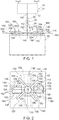
- Fig. 3 schematically illustrates examples of receptor units 160
- Fig. 4 schematically illustrates an example of a spatial relationship between receptor unit 160 and insert arm 120 while payload engagement system 100 is transitioned from the disengaged configuration to the engaged configuration.
- receptor unit 160 generally includes and/or is at least partially defined by at least one side wall 162 and at least one upper wall 164.
- Receptor unit 160 additionally may include a receptor base 166 that extends from upper surface 52 of payload 50 when receptor unit 160 is mounted on payload 50.
- receptor unit 160 may be mounted to payload 50 via receptor base 166, such as by affixing, adhering, and/or mechanically connecting receptor base 166 to upper surface 52.
- receptor unit 160 may lack receptor base 166, and or may be mounted to payload 50 via at least one side wall 162.
- receptor unit 160 additionally includes a ramp portion 168 that extends between upper surface 52 of payload 50 and receptor base 166 when receptor unit 160 is mounted on payload 50. More specifically, when present, ramp portion 168 extends oblique to upper surface 52, such as to facilitate insert arm 120 entering receptor unit 160 when payload engagement system 100 transitions from the disengaged configuration to the engaged configuration.
- ramp portion 168 extends oblique to upper surface 52, such as to facilitate insert arm 120 entering receptor unit 160 when payload engagement system 100 transitions from the disengaged configuration to the engaged configuration.
- insert arm 120 may include an insert arm base 124 such that ramp portion 168 is configured to engage insert arm base 124 to at least partially guide insert arm 120 into receptor unit 160 when payload engagement system 100 is transitioned from the disengaged configuration to the engaged configuration.
- insert arm base 124 may be at least partially rounded, such as to facilitate insert arm base 124 entering and/or exiting receptor unit 160 via contact with ramp portion 168.
- Receptor unit 160 may have any appropriate form and/or structure for receiving insert arm 120.
- some examples of receptor unit 160 include and/or define an antechamber 170 and a locking chamber 180.
- antechamber 170 may be characterized by an antechamber height 172
- locking chamber 180 may be characterized by a locking chamber height 182 that is greater than antechamber height 172.
- upper wall 164 of receptor unit 160 includes a transition region 165 between antechamber 170 and locking chamber 180, such that upper wall 164 is ramped and/or smoothly curved within transition region 165.
- Antechamber height 172 and/or locking chamber height 182 may be measured in any appropriate manner.
- antechamber height 172 may be measured between receptor base 166 and upper wall 164 in antechamber 170 and in a direction parallel to receptor component central axis 152.
- locking chamber height 182 may be measured between receptor base 166 and upper wall 164 in locking chamber 180 and in the direction parallel to receptor component central axis 152.
- antechamber height 172 may be measured between upper surface 52 of payload 50 and upper wall 164 in antechamber 170 and in the direction parallel to receptor component central axis 152 when receptor unit 160 is mounted to upper surface 52.
- locking chamber height 182 may be measured between upper surface 52 of payload 50 and upper wall 164 in locking chamber 180 and in the direction parallel to receptor component central axis 152 when receptor unit 160 is mounted to upper surface 52.
- Antechamber height 172 and locking chamber height 182 may be any appropriate respective heights, such as relative to a dimension of insert arm 120.
- insert arm 120 may have and/or be characterized by an insert arm height 122, as measured in a direction parallel to insert component central axis 112, and antechamber height 172 and/or locking chamber height 182 each may be at least 100% of insert arm height 122, at least 120% of insert arm height 122, at least 140% of insert arm height 122, at least 160% of insert arm height 122, at least 180% of insert arm height 122, at most 200% of insert arm height 122, at most 170% of insert arm height 122, at most 150% of insert arm height 122, at most 130% of insert arm height 122, and/or at most 110% of insert arm height 122.
- receptor unit 160 In an embodiment of receptor unit 160 that includes antechamber 170 and locking chamber 180, and as schematically illustrated in Fig. 4 , receptor unit 160 generally is configured such that insert arm 120 passes through antechamber 170 when payload engagement system 100 is transitioned between the disengaged configuration and the engaged configuration. As examples, in such an embodiment, insert arm 120 passes through antechamber 170 and subsequently enters locking chamber 180 when payload engagement system 100 transitions from the disengaged configuration to the engaged configuration, and insert arm 120 passes through antechamber 170 and subsequently exits receptor unit 160 when payload engagement system transitions from the engaged configuration to the disengaged configuration.
- locking chamber 180 In an embodiment of receptor unit 160 that includes antechamber 170 and locking chamber 180, locking chamber 180 generally is configured such that a corresponding insert arm 120 is received in locking chamber 180 when payload engagement system 100 is in the engaged configuration. More specifically, and as schematically illustrated in Fig. 4 , in an embodiment in which locking chamber height 182 is greater than antechamber height 172, locking chamber 180 may be described as including a locking chamber recess 184 configured to at least partially receive insert arm 120 when payload engagement system 100 is in the engaged configuration. Locking chamber recess 184 may be at least partially defined by side wall 162, upper wall 164, and/or transition region 165.
- locking chamber 180 and/or locking chamber recess 184 at least partially restricts insert arm 120 from moving within locking chamber 180 and/or rotating (such as about insert component central axis 112) when payload engagement system 100 is in the engaged configuration. More specifically, when payload engagement system 100 is in the engaged configuration, insert arm 120 is at least partially restricted from moving within locking chamber 180 by locking chamber recess 184, side wall 162, upper wall 164, and/or transition region 165. In this manner, locking chamber 180 and/or locking chamber recess 184 may facilitate maintaining payload engagement system 100 in the engaged configuration while vehicle 10 carries payload 50.
- Locking chamber recess 184 may have any appropriate dimension, such as to securely receive insert arm 120 and/or to securely restrict motion of insert arm 120.
- locking chamber recess 184 may have and/or be characterized by a recess depth 186 that is at least 10% of locking chamber height 182, at least 20% of locking chamber height 182, at least 30% of locking chamber height 182, at least 40% of locking chamber height 182, at least 50% of locking chamber height 182, at most 55% of locking chamber height 182, at most 45% of locking chamber height 182, at most 35% of locking chamber height 182, at most 25% of locking chamber height 182, and/or at most 15% of locking chamber height 182.
- recess depth 186 may describe and/or correspond to a difference between locking chamber height 182 and antechamber height 172.
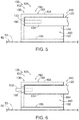
- insert arm 120 When payload engagement system 100 is in the engaged configuration, insert arm 120 may be restricted from exiting locking chamber 180 in any appropriate manner. As an example, as vehicle 10 carries payload 50, a force of gravity may at least partially retain insert arm 120 within locking chamber recess 184 by restricting insert arm 120 from translating vertically downward with respect to locking chamber recess 184, as may be required for insert arm 120 to exit locking chamber 180 (and hence receptor unit 160). Additionally or alternatively, and as schematically illustrated in Figs. 1-2 and 4-6 , insert component 110 may include a securement mechanism 130 configured to at least partially restrict payload engagement system 100 from transitioning from the engaged configuration to the disengaged configuration.
- securement mechanism 130 when present, securement mechanism 130 includes a securement engager 132 and a securement receiver 190 configured to selectively receive securement engager 132 to at least partially restrict payload engagement system 100 from transitioning from the engaged configuration to the disengaged configuration.
- securement mechanism 130 is configured to be selectively transitioned between an unlocked configuration and a locked configuration. Specifically, in the unlocked configuration, securement mechanism 130 does not restrict payload engagement system 100 from transitioning from the engaged configuration to the disengaged configuration, whereas in the locked configuration, securement mechanism 130 at least partially restricts payload engagement system 100 from transitioning from the engaged configuration to the disengaged configuration.
- Securement mechanism 130 may be incorporated into payload engagement system 100 in any appropriate manner.
- insert component 110 includes securement engager 132
- receptor component 150 includes securement receiver 190.
- at least one insert arm 120 may include securement engager 132
- at least one corresponding receptor unit 160 may include securement receiver 190.
- securement receiver 190 may be defined by side wall 162, upper wall 164, and/or receptor base 166 of receptor unit 160. In such an embodiment, securement receiver 190 receives securement engager 132 to at least partially restrict payload engagement system 100 from transitioning from the engaged configuration to the disengaged configuration.
- Securement mechanism 130, securement engager 132, and/or securement receiver 190 may have any appropriate structure.
- securement engager 132 may include and/or be a pin, a bolt, a latch, a hook, and/or a clasp.
- securement receiver 190 may include and/or be a hole, a circular hole, a slot, a vertical slot, an aperture, a bar, and/or a ledge.
- Securement receiver 190 may be configured to receive securement engager 132 in any appropriate manner. For example, securement engager 132 may extend through securement receiver 190 and/or may engage securement receiver 190 when securement mechanism 130 is in the locked configuration.
- Fig. 3 schematically illustrates examples of securement receiver 190 in the form of a circular hole (dashed lines in Fig. 3 ) and a vertical slot (dash-dot lines in Fig. 3 ), while Fig. 4 schematically illustrates an example of securement receiver 190 in the form of a circular hole.
- securement mechanism 130 in which securement receiver 190 takes the form of a hole, and as schematically illustrated in Fig. 4 , securement mechanism 130 may be configured to transition between the unlocked configuration and the locked configuration only when insert arm 120 is received within locking chamber recess 184.
- securement receiver 190 may permit securement engager 132 to translate vertically within securement receiver 190. Such an embodiment may permit securement mechanism 130 to be transitioned between the unlocked configuration and the locked configuration when insert arm 120 is in locking chamber 180, regardless of whether insert arm 120 is in locking chamber recess 184.
- Fig. 5 schematically illustrates an example of a portion of payload engagement system 100 with securement mechanism 130 in the unlocked configuration
- Fig. 6 schematically illustrates the portion of payload engagement system 100 of Fig. 5 with securement mechanism 130 in the locked configuration
- securement engager 132 takes the form of a pin
- securement receiver 190 takes the form of a hole such that securement engager 132 extends through securement receiver 190 when securement mechanism 130 is in the locked configuration
- securement engager 132 may be described as being in an extended position when securement mechanism 130 is in the locked configuration ( Fig.
- Securement engager 132 may be biased toward the extended position, may be biased toward the retracted position, or may not be biased toward either of the extended position and the retracted position.
- securement mechanism 130 additionally may include a securement mechanism actuator 134 configured to transition each securement engager 132 between the extended position and the retracted position.
- securement mechanism actuator 134 is configured to transition a corresponding securement engager 132 between the extended position and the retracted position.
- each securement engager 132 may be transitioned between the extended position and the retracted position by a unique corresponding securement mechanism actuator 134.
- securement mechanism actuator 134 may be configured to transition each of a plurality of corresponding securement engagers 132 between the extended position and the retracted position.
- Securement mechanism actuator 134 may include and/or be any appropriate mechanism for selectively transitioning securement engager 132 between the extended position and the retracted position.
- securement mechanism actuator 134 may include and/or be a motor, a servomotor, a screw drive motor, a pneumatic actuator, and/or a hydraulic actuator.
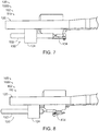
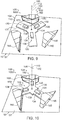
- Figs. 7-11 illustrate portions of a payload engagement system 1000, which is an example of payload engagement system 100 according to the present disclosure.
- vehicle supported portion 102 of payload engagement system 1000 includes insert component 110
- payload mounted portion 104 of payload engagement system 1000 includes receptor component 150.
- payload engagement system 1000 includes securement mechanism 130 with securement engager 132 in the form of a pin.
- Fig. 7 illustrates securement engager 132 in the retracted position
- Fig. 8 illustrates securement engager 132 in the extended position.
- payload engagement system 1000 includes three insert arms 120 and three receptor units 160. Specifically, Fig. 9 illustrates payload engagement system 1000 in the disengaged configuration, while Figs. 10-11 illustrate payload engagement system 1000 in the engaged configuration. More specifically, Fig. 10 illustrates payload engagement system 1000 in the engaged configuration and with securement mechanism 130 in the unlocked configuration, while Fig. 11 illustrates payload engagement system 1000 in the engaged configuration and with securement mechanism 130 in the locked configuration.
- Fig. 12 is a flowchart depicting methods 200, according to the present disclosure, of transporting a payload with a vehicle.
- a method 200 includes engaging, at 210, a payload (such as payload 50) with a payload engagement system (such as payload engagement system 100); transporting, at 230, the payload with a vehicle (such as vehicle 10); and disengaging, at 250, the payload with the payload engagement system.
- a method 200 includes utilizing a payload engagement system that includes a vehicle supported portion (such as vehicle supported portion 102) that is supported by the vehicle and a payload mounted portion (such as payload mounted portion 104) that is mounted to the payload.
- one of the vehicle supported portion and the payload mounted portion includes and/or is an insert component (such as insert component 110), and the other of the vehicle supported portion and the payload mounted portion includes and/or is a receptor component (such as receptor component 150) such that the insert component is selectively received within the receptor component.
- an insert component such as insert component 110
- a receptor component such as receptor component 150
- the engaging at 210 includes rotating, at 214, the vehicle supported portion with respect to the payload mounted portion to transition the payload engagement system from a disengaged configuration to an engaged configuration.
- the disengaging at 250 includes rotating, at 254, the vehicle supported portion with respect to the payload mounted portion to transition the payload engagement system from the engaged configuration to the disengaged configuration.
- the rotating at 214 and the rotating at 254 may be performed in any appropriate manner.
- the rotating at 214 and/or the rotating at 254 may include rotating the vehicle with respect to the payload to rotate the insert component with respect to the receptor component.
- the vehicle supported portion may be coupled to the vehicle via a rotary element (such as rotary element 24), and the rotating at 214 and/or the rotating at 254 may include rotating the vehicle supported portion with respect to the vehicle with the rotary element to rotate the insert component with respect to the receptor component.
- the rotating at 214 and/or the rotating at 254 may not include rotating the vehicle with respect to the payload mounted portion.
- Methods 200 may be performed with and/or utilize a payload engagement system in which the insert component includes at least two insert arms (such as insert arms 120) and the receptor component includes at least two receptor units (such as receptor units 160). More specifically, each receptor unit may include an antechamber (such as antechamber 170) and a locking chamber (such as locking chamber 180).
- the rotating at 214 may include inserting, at 216, each insert arm into the locking chamber of a respective receptor unit via the antechamber of the respective receptor unit.
- the rotating at 254 may include removing, at 256, each insert arm from the locking chamber of the respective receptor unit via the antechamber of the respective receptor unit.
- the engaging at 210 may include aligning, at 212, the insert component and the receptor component, such as prior to the rotating at 214.
- the aligning at 212 may include aligning along any appropriate dimension, such as vertically aligning and/or axially aligning.
- the aligning at 212 may include aligning such that an insert component central axis (such as insert component central axis 112) and a receptor component central axis (such a receptor component central axis 152) are at least substantially parallel and/or collinear.
- the aligning at 212 may include aligning such that an insert component plane (such as insert component plane 114) and a receptor component plane (such as receptor component plane 154) are at least substantially parallel and/or coplanar.
- the engaging at 210 may include, subsequent to the rotating at 214, lifting, at 218, the vehicle supported portion with respect to the payload mounted portion such that each insert arm is at least partially received in a locking chamber recess (such as locking chamber recess 184) of the locking chamber of the respective receptor unit.
- the lifting at 218 may include lifting such that each insert arm is rotationally constrained within each respective locking chamber. Additionally or alternatively, the lifting at 218 may include lifting such that each insert arm contacts an upper wall (such as upper wall 164) of the respective receptor unit.
- the engaging at 210 additionally may include securing, at 220, the insert component in the engaged configuration via at least one securement mechanism (such as securement mechanism 130).
- the securing at 220 may include transitioning each securement mechanism from an unlocked configuration to a locked configuration, such as to at least partially restrict the payload engagement system from transitioning to the disengaged configuration.
- the lifting at 218 and the securing at 220 may be performed in any appropriate sequence. As examples, the securing at 220 may be performed prior to the lifting at 218, or may be performed subsequent to the lifting at 218.
- the transporting at 230 may be performed in any appropriate manner.
- the transporting at 230 may include transporting such that the receptor component central axis remains at least substantially parallel to a vertical axis (such as vertical axis 106).
- the transporting at 230 may include pivoting, at 232, the vehicle supported portion with respect to the vehicle with a gimbal (such as gimbal 22), such as to maintain the receptor component central axis in an orientation that is at least substantially parallel to the vertical axis.
- the vehicle includes and/or is an aircraft (such as aircraft 11), such as a rotorcraft and/or a UAV
- the aircraft may tilt relative to a ground surface toward a direction in which the aircraft travels.
- the pivoting at 232 may include pivoting the vehicle supported portion with respect to the aircraft such that the payload remains at least substantially upright as the aircraft tilts with respect to the ground surface.
- the disengaging at 250 may be performed in any appropriate manner.
- the disengaging at 250 may include, prior to the rotating at 254, lowering, at 252, the vehicle supported portion with respect to the payload mounted portion.
- the lowering at 252 when performed, includes lowering such that each insert arm is removed from the locking chamber recess of the respective receptor unit, such as to permit the insert arm to rotate with respect to the receptor unit.
- the lowering at 252 may include lowering such that each insert arm contacts a receptor base (such as receptor base 166) of the respective receptor unit.
- the disengaging at 250 additionally may include releasing, at 258, the insert component by transitioning each securement mechanism from the locked configuration to the unlocked configuration.
- the releasing at 258 may include releasing such that the securement mechanism ceases to restrict the payload engagement system from transitioning to the disengaged configuration.
- the lowering at 252 and the releasing at 258 may be performed in any appropriate sequence. As examples, the releasing at 258 may be performed prior to the lowering at 252, or may be performed subsequent to the lowering at 252.
- the terms “adapted” and “configured” mean that the element, component, or other subject matter is designed and/or intended to perform a given function. Thus, the use of the terms “adapted” and “configured” should not be construed to mean that a given element, component, or other subject matter is simply “capable of” performing a given function but that the element, component, and/or other subject matter is specifically selected, created, implemented, utilized, programmed, and/or designed for the purpose of performing the function. It is also within the scope of the present disclosure that elements, components, and/or other recited subject matter that is recited as being adapted to perform a particular function may additionally or alternatively be described as being configured to perform that function, and vice versa. Similarly, subject matter that is recited as being configured to perform a particular function may additionally or alternatively be described as being operative to perform that function.
- the term "and/or" placed between a first entity and a second entity means one of (1) the first entity, (2) the second entity, and (3) the first entity and the second entity.
- Multiple entries listed with “and/or” should be construed in the same manner, i.e., "one or more" of the entities so conjoined.
- Other entities optionally may be present other than the entities specifically identified by the "and/or” clause, whether related or unrelated to those entities specifically identified.
- a reference to "A and/or B,” when used in conjunction with open-ended language such as “comprising,” may refer, in one example, to A only (optionally including entities other than B); in another example, to B only (optionally including entities other than A); in yet another example, to both A and B (optionally including other entities).
- These entities may refer to elements, actions, structures, steps, operations, values, and the like.
Landscapes
- Engineering & Computer Science (AREA)
- Aviation & Aerospace Engineering (AREA)
- Connection Of Plates (AREA)
Applications Claiming Priority (1)
| Application Number | Priority Date | Filing Date | Title |
|---|---|---|---|
| US15/954,426 US10814983B2 (en) | 2018-04-16 | 2018-04-16 | Payload engagement systems, vehicles including the same, and related methods |
Publications (2)
| Publication Number | Publication Date |
|---|---|
| EP3556654A1 true EP3556654A1 (de) | 2019-10-23 |
| EP3556654B1 EP3556654B1 (de) | 2022-01-05 |
Family
ID=66041156
Family Applications (1)
| Application Number | Title | Priority Date | Filing Date |
|---|---|---|---|
| EP19165955.6A Active EP3556654B1 (de) | 2018-04-16 | 2019-03-28 | Nutzlasteingriffssysteme, fahrzeuge damit und zugehörige verfahren |
Country Status (5)
| Country | Link |
|---|---|
| US (1) | US10814983B2 (de) |
| EP (1) | EP3556654B1 (de) |
| JP (1) | JP7312595B2 (de) |
| CN (1) | CN110386251B (de) |
| CA (1) | CA3036873C (de) |
Cited By (2)
| Publication number | Priority date | Publication date | Assignee | Title |
|---|---|---|---|---|
| US10814983B2 (en) * | 2018-04-16 | 2020-10-27 | The Boeing Company | Payload engagement systems, vehicles including the same, and related methods |
| FR3107096A1 (fr) * | 2020-02-11 | 2021-08-13 | Airbus (S.A.S.) | Assemblage comprenant deux platines reliées par au moins deux systèmes d’attache contrôlés par un même système d’actionnement, véhicule comprenant au moins un tel assemblage et procédé de transfert d’un module de transport entre deux tels assemblages |
Families Citing this family (2)
| Publication number | Priority date | Publication date | Assignee | Title |
|---|---|---|---|---|
| US12312085B2 (en) * | 2023-05-18 | 2025-05-27 | Performance Drone Works Llc | Mechanical release device for unmanned aerial vehicle drop-payload |
| WO2025097094A2 (en) * | 2023-11-03 | 2025-05-08 | Ogden Gabriel | Using an aerial drone with a drone mounted interface to dock an adapted payload to a surface mounted interface |
Citations (6)
| Publication number | Priority date | Publication date | Assignee | Title |
|---|---|---|---|---|
| WO1989002988A1 (en) * | 1987-09-22 | 1989-04-06 | Hiroya Kato | Locking device and product using same |
| DE102004035627B3 (de) * | 2004-07-22 | 2006-05-18 | Schührer, Bernhard | Vorrichtung zur Kopplung zweier Bauteile und eine Verwendung einer derartigen Vorrichtung |
| US20140353994A1 (en) * | 2013-06-04 | 2014-12-04 | Caterpillar Inc. | Latching Apparatus for Sequentially Latching and Unlatching Object |
| US20170158144A1 (en) * | 2015-12-03 | 2017-06-08 | Textron Inc. | Accessory attachment system |
| DE102016104418A1 (de) * | 2016-03-10 | 2017-09-14 | Deva-Kunststofftechnik Gmbh | Befestigungsvorrichtung für ein Fahrzeug und Baukastensystem mit der Befestigungsvorrichtung |
| US20170267347A1 (en) * | 2015-10-14 | 2017-09-21 | Flirtey Holdings, Inc. | Package delivery mechanism in an unmanned aerial vehicle |
Family Cites Families (9)
| Publication number | Priority date | Publication date | Assignee | Title |
|---|---|---|---|---|
| JPS6032056Y2 (ja) * | 1981-09-11 | 1985-09-25 | 日立造船株式会社 | 容器蓋着脱兼容器吊上げ装置 |
| US7713009B2 (en) * | 2006-03-31 | 2010-05-11 | The Boeing Company | Apparatus and methods for removably securing payloads in an aircraft |
| DE102007011613B4 (de) * | 2007-01-22 | 2011-07-28 | Airbus Operations GmbH, 21129 | Beschlag zur Einleitung von hohen Kräften in eine Rumpfzelle eines Flugzeugs |
| FR2970944B1 (fr) * | 2011-01-27 | 2013-02-08 | Eurocopter France | Dispositif de fixation amovible muni d'un moyen d'accrochage d'une charge externe et d'un moyen de fixation dudit moyen d'accrochage a un aeronef, aeronef et procede associes |
| US20160272310A1 (en) * | 2014-12-04 | 2016-09-22 | Elwha Llc | Reconfigurable unmanned aircraft system |
| KR101535401B1 (ko) | 2015-04-01 | 2015-07-08 | 오인선 | 드론방식 구명장비 투하장치 |
| JP6340020B2 (ja) | 2016-01-08 | 2018-06-06 | Jfe物流株式会社 | コイルリフター |
| US10814983B2 (en) * | 2018-04-16 | 2020-10-27 | The Boeing Company | Payload engagement systems, vehicles including the same, and related methods |
| US11453498B2 (en) * | 2018-07-27 | 2022-09-27 | The Boeing Company | Payload engagement systems and related methods |
-
2018
- 2018-04-16 US US15/954,426 patent/US10814983B2/en active Active
-
2019
- 2019-03-14 CA CA3036873A patent/CA3036873C/en active Active
- 2019-03-28 EP EP19165955.6A patent/EP3556654B1/de active Active
- 2019-04-15 JP JP2019076796A patent/JP7312595B2/ja active Active
- 2019-04-15 CN CN201910297223.1A patent/CN110386251B/zh active Active
Patent Citations (6)
| Publication number | Priority date | Publication date | Assignee | Title |
|---|---|---|---|---|
| WO1989002988A1 (en) * | 1987-09-22 | 1989-04-06 | Hiroya Kato | Locking device and product using same |
| DE102004035627B3 (de) * | 2004-07-22 | 2006-05-18 | Schührer, Bernhard | Vorrichtung zur Kopplung zweier Bauteile und eine Verwendung einer derartigen Vorrichtung |
| US20140353994A1 (en) * | 2013-06-04 | 2014-12-04 | Caterpillar Inc. | Latching Apparatus for Sequentially Latching and Unlatching Object |
| US20170267347A1 (en) * | 2015-10-14 | 2017-09-21 | Flirtey Holdings, Inc. | Package delivery mechanism in an unmanned aerial vehicle |
| US20170158144A1 (en) * | 2015-12-03 | 2017-06-08 | Textron Inc. | Accessory attachment system |
| DE102016104418A1 (de) * | 2016-03-10 | 2017-09-14 | Deva-Kunststofftechnik Gmbh | Befestigungsvorrichtung für ein Fahrzeug und Baukastensystem mit der Befestigungsvorrichtung |
Cited By (2)
| Publication number | Priority date | Publication date | Assignee | Title |
|---|---|---|---|---|
| US10814983B2 (en) * | 2018-04-16 | 2020-10-27 | The Boeing Company | Payload engagement systems, vehicles including the same, and related methods |
| FR3107096A1 (fr) * | 2020-02-11 | 2021-08-13 | Airbus (S.A.S.) | Assemblage comprenant deux platines reliées par au moins deux systèmes d’attache contrôlés par un même système d’actionnement, véhicule comprenant au moins un tel assemblage et procédé de transfert d’un module de transport entre deux tels assemblages |
Also Published As
| Publication number | Publication date |
|---|---|
| US10814983B2 (en) | 2020-10-27 |
| CN110386251A (zh) | 2019-10-29 |
| CA3036873A1 (en) | 2019-10-16 |
| US20190315466A1 (en) | 2019-10-17 |
| JP7312595B2 (ja) | 2023-07-21 |
| CN110386251B (zh) | 2024-08-30 |
| EP3556654B1 (de) | 2022-01-05 |
| JP2019206328A (ja) | 2019-12-05 |
| CA3036873C (en) | 2023-08-01 |
Similar Documents
| Publication | Publication Date | Title |
|---|---|---|
| EP3556654A1 (de) | Nutzlasteingriffssysteme, fahrzeuge damit und zugehörige verfahren | |
| JP7285847B2 (ja) | 無人航空機 | |
| US20210237901A1 (en) | Aircraft-retrieval system | |
| US11352133B2 (en) | Systems, cableless drone swarm systems, method and apparatus | |
| EP3984885B1 (de) | Modulares anschlusssystem für ein unbemanntes luftfahrzeug | |
| US10293929B2 (en) | Multicopter-assisted system and method for launching and retrieving a fixed-wing aircraft | |
| US10633088B2 (en) | Aerial imaging aircraft having attitude stability during translation | |
| US10604249B2 (en) | Man portable aircraft system for rapid in-situ assembly | |
| US8366049B2 (en) | Hover delivery of cabin payload in tilt-rotor and tilt-wing aircraft | |
| US20170327206A1 (en) | Multicopter-assisted system and method for launching and retrieving a fixed-wing aircraft | |
| WO2018066043A1 (ja) | 配達用回転翼機 | |
| US20150284079A1 (en) | Winged multi-rotor flying craft with payload accomodating shifting structure and automatic payload delivery | |
| IL290392B1 (en) | aircraft | |
| US20150259066A1 (en) | Hovering unmanned aerial vehicle | |
| EP4151526B1 (de) | Luftfahrzeug mit sechs freiheitsgraden mit rekonfigurierbaren motoren, propellern oder flügeln | |
| US20200086986A1 (en) | Six degree of freedom aerial vehicle having pivoting wing sections | |
| TWI593451B (zh) | Unmanned vehicle battery replacement system | |
| CN105383705A (zh) | 一种车载式无人机弹射装置 | |
| US11643219B1 (en) | Reconfigurable propulsion mechanisms of a multirotor aerial vehicle | |
| US9989098B2 (en) | System and method of rotating rotor blades from a distance | |
| CN109204815A (zh) | 一种机翼稳定转动并自锁的折叠式无人机 | |
| US12434822B2 (en) | Method of assemblying and operating an autorotating payload delivery device | |
| KR102261915B1 (ko) | 무인비행체의 적재함 체결장치 | |
| CN114212235A (zh) | 飞机、载货系统、飞机拆卸方法以及安装方法 | |
| CN118579265B (zh) | 一种大载重无人机用载重装置 |
Legal Events
| Date | Code | Title | Description |
|---|---|---|---|
| PUAI | Public reference made under article 153(3) epc to a published international application that has entered the european phase |
Free format text: ORIGINAL CODE: 0009012 |
|
| STAA | Information on the status of an ep patent application or granted ep patent |
Free format text: STATUS: REQUEST FOR EXAMINATION WAS MADE |
|
| 17P | Request for examination filed |
Effective date: 20190328 |
|
| AK | Designated contracting states |
Kind code of ref document: A1 Designated state(s): AL AT BE BG CH CY CZ DE DK EE ES FI FR GB GR HR HU IE IS IT LI LT LU LV MC MK MT NL NO PL PT RO RS SE SI SK SM TR |
|
| AX | Request for extension of the european patent |
Extension state: BA ME |
|
| STAA | Information on the status of an ep patent application or granted ep patent |
Free format text: STATUS: EXAMINATION IS IN PROGRESS |
|
| 17Q | First examination report despatched |
Effective date: 20201113 |
|
| GRAP | Despatch of communication of intention to grant a patent |
Free format text: ORIGINAL CODE: EPIDOSNIGR1 |
|
| STAA | Information on the status of an ep patent application or granted ep patent |
Free format text: STATUS: GRANT OF PATENT IS INTENDED |
|
| INTG | Intention to grant announced |
Effective date: 20210818 |
|
| GRAS | Grant fee paid |
Free format text: ORIGINAL CODE: EPIDOSNIGR3 |
|
| GRAA | (expected) grant |
Free format text: ORIGINAL CODE: 0009210 |
|
| STAA | Information on the status of an ep patent application or granted ep patent |
Free format text: STATUS: THE PATENT HAS BEEN GRANTED |
|
| AK | Designated contracting states |
Kind code of ref document: B1 Designated state(s): AL AT BE BG CH CY CZ DE DK EE ES FI FR GB GR HR HU IE IS IT LI LT LU LV MC MK MT NL NO PL PT RO RS SE SI SK SM TR |
|
| REG | Reference to a national code |
Ref country code: GB Ref legal event code: FG4D |
|
| REG | Reference to a national code |
Ref country code: CH Ref legal event code: EP |
|
| REG | Reference to a national code |
Ref country code: AT Ref legal event code: REF Ref document number: 1460321 Country of ref document: AT Kind code of ref document: T Effective date: 20220115 |
|
| REG | Reference to a national code |
Ref country code: DE Ref legal event code: R096 Ref document number: 602019010560 Country of ref document: DE |
|
| REG | Reference to a national code |
Ref country code: IE Ref legal event code: FG4D |
|
| REG | Reference to a national code |
Ref country code: LT Ref legal event code: MG9D |
|
| REG | Reference to a national code |
Ref country code: NL Ref legal event code: MP Effective date: 20220105 |
|
| REG | Reference to a national code |
Ref country code: AT Ref legal event code: MK05 Ref document number: 1460321 Country of ref document: AT Kind code of ref document: T Effective date: 20220105 |
|
| PG25 | Lapsed in a contracting state [announced via postgrant information from national office to epo] |
Ref country code: NL Free format text: LAPSE BECAUSE OF FAILURE TO SUBMIT A TRANSLATION OF THE DESCRIPTION OR TO PAY THE FEE WITHIN THE PRESCRIBED TIME-LIMIT Effective date: 20220105 |
|
| PG25 | Lapsed in a contracting state [announced via postgrant information from national office to epo] |
Ref country code: SE Free format text: LAPSE BECAUSE OF FAILURE TO SUBMIT A TRANSLATION OF THE DESCRIPTION OR TO PAY THE FEE WITHIN THE PRESCRIBED TIME-LIMIT Effective date: 20220105 Ref country code: RS Free format text: LAPSE BECAUSE OF FAILURE TO SUBMIT A TRANSLATION OF THE DESCRIPTION OR TO PAY THE FEE WITHIN THE PRESCRIBED TIME-LIMIT Effective date: 20220105 Ref country code: PT Free format text: LAPSE BECAUSE OF FAILURE TO SUBMIT A TRANSLATION OF THE DESCRIPTION OR TO PAY THE FEE WITHIN THE PRESCRIBED TIME-LIMIT Effective date: 20220505 Ref country code: NO Free format text: LAPSE BECAUSE OF FAILURE TO SUBMIT A TRANSLATION OF THE DESCRIPTION OR TO PAY THE FEE WITHIN THE PRESCRIBED TIME-LIMIT Effective date: 20220405 Ref country code: LT Free format text: LAPSE BECAUSE OF FAILURE TO SUBMIT A TRANSLATION OF THE DESCRIPTION OR TO PAY THE FEE WITHIN THE PRESCRIBED TIME-LIMIT Effective date: 20220105 Ref country code: HR Free format text: LAPSE BECAUSE OF FAILURE TO SUBMIT A TRANSLATION OF THE DESCRIPTION OR TO PAY THE FEE WITHIN THE PRESCRIBED TIME-LIMIT Effective date: 20220105 Ref country code: ES Free format text: LAPSE BECAUSE OF FAILURE TO SUBMIT A TRANSLATION OF THE DESCRIPTION OR TO PAY THE FEE WITHIN THE PRESCRIBED TIME-LIMIT Effective date: 20220105 Ref country code: BG Free format text: LAPSE BECAUSE OF FAILURE TO SUBMIT A TRANSLATION OF THE DESCRIPTION OR TO PAY THE FEE WITHIN THE PRESCRIBED TIME-LIMIT Effective date: 20220405 |
|
| PG25 | Lapsed in a contracting state [announced via postgrant information from national office to epo] |
Ref country code: PL Free format text: LAPSE BECAUSE OF FAILURE TO SUBMIT A TRANSLATION OF THE DESCRIPTION OR TO PAY THE FEE WITHIN THE PRESCRIBED TIME-LIMIT Effective date: 20220105 Ref country code: LV Free format text: LAPSE BECAUSE OF FAILURE TO SUBMIT A TRANSLATION OF THE DESCRIPTION OR TO PAY THE FEE WITHIN THE PRESCRIBED TIME-LIMIT Effective date: 20220105 Ref country code: GR Free format text: LAPSE BECAUSE OF FAILURE TO SUBMIT A TRANSLATION OF THE DESCRIPTION OR TO PAY THE FEE WITHIN THE PRESCRIBED TIME-LIMIT Effective date: 20220406 Ref country code: FI Free format text: LAPSE BECAUSE OF FAILURE TO SUBMIT A TRANSLATION OF THE DESCRIPTION OR TO PAY THE FEE WITHIN THE PRESCRIBED TIME-LIMIT Effective date: 20220105 Ref country code: AT Free format text: LAPSE BECAUSE OF FAILURE TO SUBMIT A TRANSLATION OF THE DESCRIPTION OR TO PAY THE FEE WITHIN THE PRESCRIBED TIME-LIMIT Effective date: 20220105 |
|
| PG25 | Lapsed in a contracting state [announced via postgrant information from national office to epo] |
Ref country code: IS Free format text: LAPSE BECAUSE OF FAILURE TO SUBMIT A TRANSLATION OF THE DESCRIPTION OR TO PAY THE FEE WITHIN THE PRESCRIBED TIME-LIMIT Effective date: 20220505 |
|
| REG | Reference to a national code |
Ref country code: DE Ref legal event code: R097 Ref document number: 602019010560 Country of ref document: DE |
|
| PG25 | Lapsed in a contracting state [announced via postgrant information from national office to epo] |
Ref country code: SM Free format text: LAPSE BECAUSE OF FAILURE TO SUBMIT A TRANSLATION OF THE DESCRIPTION OR TO PAY THE FEE WITHIN THE PRESCRIBED TIME-LIMIT Effective date: 20220105 Ref country code: SK Free format text: LAPSE BECAUSE OF FAILURE TO SUBMIT A TRANSLATION OF THE DESCRIPTION OR TO PAY THE FEE WITHIN THE PRESCRIBED TIME-LIMIT Effective date: 20220105 Ref country code: RO Free format text: LAPSE BECAUSE OF FAILURE TO SUBMIT A TRANSLATION OF THE DESCRIPTION OR TO PAY THE FEE WITHIN THE PRESCRIBED TIME-LIMIT Effective date: 20220105 Ref country code: MC Free format text: LAPSE BECAUSE OF FAILURE TO SUBMIT A TRANSLATION OF THE DESCRIPTION OR TO PAY THE FEE WITHIN THE PRESCRIBED TIME-LIMIT Effective date: 20220105 Ref country code: EE Free format text: LAPSE BECAUSE OF FAILURE TO SUBMIT A TRANSLATION OF THE DESCRIPTION OR TO PAY THE FEE WITHIN THE PRESCRIBED TIME-LIMIT Effective date: 20220105 Ref country code: DK Free format text: LAPSE BECAUSE OF FAILURE TO SUBMIT A TRANSLATION OF THE DESCRIPTION OR TO PAY THE FEE WITHIN THE PRESCRIBED TIME-LIMIT Effective date: 20220105 Ref country code: CZ Free format text: LAPSE BECAUSE OF FAILURE TO SUBMIT A TRANSLATION OF THE DESCRIPTION OR TO PAY THE FEE WITHIN THE PRESCRIBED TIME-LIMIT Effective date: 20220105 |
|
| REG | Reference to a national code |
Ref country code: CH Ref legal event code: PL |
|
| PLBE | No opposition filed within time limit |
Free format text: ORIGINAL CODE: 0009261 |
|
| STAA | Information on the status of an ep patent application or granted ep patent |
Free format text: STATUS: NO OPPOSITION FILED WITHIN TIME LIMIT |
|
| PG25 | Lapsed in a contracting state [announced via postgrant information from national office to epo] |
Ref country code: AL Free format text: LAPSE BECAUSE OF FAILURE TO SUBMIT A TRANSLATION OF THE DESCRIPTION OR TO PAY THE FEE WITHIN THE PRESCRIBED TIME-LIMIT Effective date: 20220105 |
|
| REG | Reference to a national code |
Ref country code: BE Ref legal event code: MM Effective date: 20220331 |
|
| 26N | No opposition filed |
Effective date: 20221006 |
|
| PG25 | Lapsed in a contracting state [announced via postgrant information from national office to epo] |
Ref country code: LU Free format text: LAPSE BECAUSE OF NON-PAYMENT OF DUE FEES Effective date: 20220328 Ref country code: LI Free format text: LAPSE BECAUSE OF NON-PAYMENT OF DUE FEES Effective date: 20220331 Ref country code: IE Free format text: LAPSE BECAUSE OF NON-PAYMENT OF DUE FEES Effective date: 20220328 Ref country code: CH Free format text: LAPSE BECAUSE OF NON-PAYMENT OF DUE FEES Effective date: 20220331 |
|
| PG25 | Lapsed in a contracting state [announced via postgrant information from national office to epo] |
Ref country code: SI Free format text: LAPSE BECAUSE OF FAILURE TO SUBMIT A TRANSLATION OF THE DESCRIPTION OR TO PAY THE FEE WITHIN THE PRESCRIBED TIME-LIMIT Effective date: 20220105 Ref country code: BE Free format text: LAPSE BECAUSE OF NON-PAYMENT OF DUE FEES Effective date: 20220331 |
|
| P01 | Opt-out of the competence of the unified patent court (upc) registered |
Effective date: 20230516 |
|
| PG25 | Lapsed in a contracting state [announced via postgrant information from national office to epo] |
Ref country code: IT Free format text: LAPSE BECAUSE OF FAILURE TO SUBMIT A TRANSLATION OF THE DESCRIPTION OR TO PAY THE FEE WITHIN THE PRESCRIBED TIME-LIMIT Effective date: 20220105 |
|
| PG25 | Lapsed in a contracting state [announced via postgrant information from national office to epo] |
Ref country code: MK Free format text: LAPSE BECAUSE OF FAILURE TO SUBMIT A TRANSLATION OF THE DESCRIPTION OR TO PAY THE FEE WITHIN THE PRESCRIBED TIME-LIMIT Effective date: 20220105 Ref country code: CY Free format text: LAPSE BECAUSE OF FAILURE TO SUBMIT A TRANSLATION OF THE DESCRIPTION OR TO PAY THE FEE WITHIN THE PRESCRIBED TIME-LIMIT Effective date: 20220105 |
|
| PG25 | Lapsed in a contracting state [announced via postgrant information from national office to epo] |
Ref country code: HU Free format text: LAPSE BECAUSE OF FAILURE TO SUBMIT A TRANSLATION OF THE DESCRIPTION OR TO PAY THE FEE WITHIN THE PRESCRIBED TIME-LIMIT; INVALID AB INITIO Effective date: 20190328 |
|
| PG25 | Lapsed in a contracting state [announced via postgrant information from national office to epo] |
Ref country code: MT Free format text: LAPSE BECAUSE OF FAILURE TO SUBMIT A TRANSLATION OF THE DESCRIPTION OR TO PAY THE FEE WITHIN THE PRESCRIBED TIME-LIMIT Effective date: 20220105 |
|
| PGFP | Annual fee paid to national office [announced via postgrant information from national office to epo] |
Ref country code: DE Payment date: 20250327 Year of fee payment: 7 |
|
| PGFP | Annual fee paid to national office [announced via postgrant information from national office to epo] |
Ref country code: FR Payment date: 20250325 Year of fee payment: 7 |
|
| PGFP | Annual fee paid to national office [announced via postgrant information from national office to epo] |
Ref country code: GB Payment date: 20250327 Year of fee payment: 7 |
|
| PG25 | Lapsed in a contracting state [announced via postgrant information from national office to epo] |
Ref country code: TR Free format text: LAPSE BECAUSE OF FAILURE TO SUBMIT A TRANSLATION OF THE DESCRIPTION OR TO PAY THE FEE WITHIN THE PRESCRIBED TIME-LIMIT Effective date: 20220105 |