EP3556606B1 - Vorrichtung zur lagerung von kisten - Google Patents
Vorrichtung zur lagerung von kisten Download PDFInfo
- Publication number
- EP3556606B1 EP3556606B1 EP19165265.0A EP19165265A EP3556606B1 EP 3556606 B1 EP3556606 B1 EP 3556606B1 EP 19165265 A EP19165265 A EP 19165265A EP 3556606 B1 EP3556606 B1 EP 3556606B1
- Authority
- EP
- European Patent Office
- Prior art keywords
- tub
- slot
- trough
- traction means
- boxes
- Prior art date
- Legal status (The legal status is an assumption and is not a legal conclusion. Google has not performed a legal analysis and makes no representation as to the accuracy of the status listed.)
- Active
Links
Images

Classifications
-
- B—PERFORMING OPERATIONS; TRANSPORTING
- B60—VEHICLES IN GENERAL
- B60P—VEHICLES ADAPTED FOR LOAD TRANSPORTATION OR TO TRANSPORT, TO CARRY, OR TO COMPRISE SPECIAL LOADS OR OBJECTS
- B60P3/00—Vehicles adapted to transport, to carry or to comprise special loads or objects
- B60P3/055—Vehicles adapted to transport, to carry or to comprise special loads or objects for transporting bottles
-
- B—PERFORMING OPERATIONS; TRANSPORTING
- B60—VEHICLES IN GENERAL
- B60P—VEHICLES ADAPTED FOR LOAD TRANSPORTATION OR TO TRANSPORT, TO CARRY, OR TO COMPRISE SPECIAL LOADS OR OBJECTS
- B60P7/00—Securing or covering of load on vehicles
- B60P7/06—Securing of load
- B60P7/08—Securing to the vehicle floor or sides
- B60P7/0807—Attachment points
- B60P7/0815—Attachment rails or trellis
-
- B—PERFORMING OPERATIONS; TRANSPORTING
- B60—VEHICLES IN GENERAL
- B60P—VEHICLES ADAPTED FOR LOAD TRANSPORTATION OR TO TRANSPORT, TO CARRY, OR TO COMPRISE SPECIAL LOADS OR OBJECTS
- B60P7/00—Securing or covering of load on vehicles
- B60P7/06—Securing of load
- B60P7/08—Securing to the vehicle floor or sides
- B60P7/0823—Straps; Tighteners
-
- B—PERFORMING OPERATIONS; TRANSPORTING
- B60—VEHICLES IN GENERAL
- B60P—VEHICLES ADAPTED FOR LOAD TRANSPORTATION OR TO TRANSPORT, TO CARRY, OR TO COMPRISE SPECIAL LOADS OR OBJECTS
- B60P7/00—Securing or covering of load on vehicles
- B60P7/06—Securing of load
- B60P7/08—Securing to the vehicle floor or sides
- B60P7/10—Securing to the vehicle floor or sides the load being plates, cases, or boxes
Definitions
- the invention relates to a device for storing boxes according to the preamble of claim 1.
- the invention is used for storing and transporting beverage crates in vehicles where the beverage crates not only have to be safely parked, but also before falling down when the moving vehicle is shaken protect are.
- the DE 195 14 605 A1 describes a device for storing containers in the trunk of a vehicle with a bottom part and two side parts which form a type of tub.
- the bottom part has a slot which runs parallel to the side parts and in which a belt holder is slidably mounted.
- the belt can be stretched over the container to be stored and attached to an identically designed belt holder which is also guided in the slot, so that the item of luggage or the container is secured.
- the DE 199 49 550 A1 relates to a transport system, a transport container being cuboid and standardized with regard to its external dimensions, the associated transport means and fastening means for positioning and fixing on the transport means being designed in accordance with this standard.
- Subject of GB 847,792 are receiving areas for the loading area of trucks, for the safe storage of the goods to be transported.
- the task is to design a device for storing crates, in particular beverage crates, inside a vehicle in such a way that the crates can be removed without too much force and a safe, reliable, low-noise and low-wear storage is then provided when the vehicle is moving on uneven ground.
- the box storage device has a base frame with several rack posts or side walls, and at least one elongated tub with a rectangular bottom and one or two long sides, the bottom having a slot running parallel to the long sides in which a slider is slidably mounted one end of a flexible traction means is attached.
- the other end of this flexible traction means is arranged on a broad side of the side wall, which is located in the front area of the device facing the user.
- On this broad side there is a clamping device for the flexible traction means so that it can be clamped there.
- Another broad side can be arranged on the rear of the tub. This then runs parallel to the first broad side.
- the tub is inclined at an angle of 8 ° to 20 °, so that the boxes stored in it slide forward in the direction of the user due to the force of gravity. When the front box is removed, those behind it slide along.
- the clear width of the tub i.e. the distance between the two long sides, is between 25 cm and 50 cm and the length of the tub, i.e. the distance between the two broad sides to accommodate four to six commercial beverage crates between 80 cm and 250 cm.
- the base frame has several shelf posts or side walls in which several trays can advantageously be accommodated one above the other.
- the flexible traction means is a rope or a belt.
- the sliding piece consists of a sliding block located essentially above the slot and a counterplate which is located essentially below the slot and is connected to the sliding block.
- the clamping device is preferably designed as a Curry clamp.
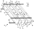
- the Figures 1 - 3 show the device according to the invention for storing crates 1, here beverage crates 1, on the basis of an exemplary embodiment in which three tubs 2 lying one above the other are located within a base frame consisting of four shelf posts 12.
- the shelf posts 12 are commercially available shelf posts made of a steel or aluminum profile with holes or bores for receiving shelf supports, whereby shelves or, as in the present case, tubs 2 are attached between the shelf posts 12 and can be screwed to them.
- Both the shelf posts and - in an alternative embodiment - side walls and the tubs themselves can be made of sheet metal or wood or plastic or some other suitable material.
- each tub 2 has a base 3 and an adjoining, upwardly projecting side wall, each side wall consisting of two long sides 4 or 5 and two broad sides 6 or 7 exists.
- the front broad sides 6 of each side wall of each tub 3 are less high than the other parts of the side wall, namely the rear broad side 7 and the two long sides 4 and 5, in order to facilitate the removal of the beverage crates 1 via the front broad side 6 .
- the tubs 2 are arranged between the shelf posts 12 and attached to them in such a way that, viewed from the rear broad sides 7 to the front broad sides 6, they are inclined forward at an angle of approximately 12 °.
- the front broad side 6, on which the tubs 2 with the beverage crates 1 are filled and emptied, is thus lower than the rear broad side 7.
- the distance between the two long sides 4 and 5 from one another is selected so that commercially available beverage crates 1 fit into the tub 2 with little play.
- the length of the tub 2, that is to say the distance between the two broad sides 6 and 7 from one another, is selected such that between three and six beverage crates 1 can be pushed into each tub 2.
- Each trough 2 has approximately in the middle of its bottom 3, that is to say centrally between the two longitudinal sides 4 and 5, a continuous slot 8 running parallel to these longitudinal sides 4 and 5, respectively.
- the slot ends shortly before the rear broad side 7 and at a somewhat greater distance in front of the front broad side 6.
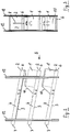
- the Figures 4 and 5 show a plan view of an alternative embodiment of a tub 2, in which the base 3 is somewhat deeper in the central area than in the edge area.
- boxes with a smaller width can also be safely received, which boxes fit exactly into the central area of the base 3, while the boxes with a greater width rest on the edge area of the base.
- the wider boxes which rest on the edge area of the base 3 can be beer carriers, while the narrower boxes which lie on the central area of the base 3 are mineral water boxes.
- the sliding piece 9 consists of a sliding block 13 located essentially above the slot 8 and a sliding block 13 located essentially below the slot 8 Composed counter plate 14, which is connected to the sliding block 13 by a screw connection which extends through the slot 8.
- the sliding block 13 has a protrusion which engages exactly in the slot 8, while the counter plate 14 is flat and only has an opening for the passage of a screw that can be screwed into a corresponding thread of the sliding block, whereby it must be ensured that between the sliding block 13 and the counter plate 14 a sufficient distance that exceeds the thickness of the bottom 3 of the tub 2 remains, so that a slight displacement of the sliding piece 9 within the slot 8 is possible.
- Fig. 1 On the sliding piece 9, in particular on the sliding block 13, is how Fig. 1 it can be seen that the end of a flexible traction means 10 is attached.
- This can be, for example, a rope or a belt.
- the flexible traction means 10 is in use of the device as shown in Fig. 1 , lowest tub 2, is shown, guided over the beverage crate or crates 1 to be transported within the tub 2 and fixed on the front broad side 6 of the tub 2, which has a clamping device 11 for this purpose.
- a clamping device for ropes is known, for example, from sailing as a curry clamp.
- other clamping devices or fastening devices for the free end of the flexible traction means 10 are also possible.
- the flexible traction means 10 is not attached to the front broad side 6 of the same tub 2 to which it is attached via the associated sliding block, but rather to the front broad side 6 of the tub 2 arranged above it.
- the beverage crates 1 or other crates or crates are lifted over the front broad side 6 and placed on the floor 3 of the tub 2. If several beverage crates 1 are to be transported, each beverage crate 1 is pushed backwards towards the rear broad side 7 when a further beverage crate 1 is added onto the bottom 3 of the tub. Here, the slider 9 moves within the slot 8 to the rear.
- the flexible traction means 10 i.e. the belt or the rope
- the free end of the traction means 10 then attached to the clamping device 11 on the broad side 6 of the side wall of the tub 2 or on the broad side 6 of the tub 2 arranged above it.
- the beverage crates 1 are securely anchored in the tub 2 and thus in the vehicle. They cannot hop, slip or rattle, make no noise or wear, and they cannot fall out of the tub 2.
- the clamping device 11 of the flexible pulling means 10 is released and the flexible pulling means 10 is removed from the clamping device 11.
- the beverage crates 1 can then be removed, whereby, due to the inclination of the tub, the beverage crates 1 either slide forward by themselves or can be pulled forward with little effort in order to then be removed via the front broad side 6 of the side wall of the tub 2.
- the sliding piece 9 moves by itself along the slot 8 forwards in the direction of the front broad side 6 or is pulled forwards by hand by means of the flexible traction means 10.
- the free end of the flexible traction means 11 can then be fixed to the tub 2 again via the clamping device.
Landscapes
- Engineering & Computer Science (AREA)
- Transportation (AREA)
- Mechanical Engineering (AREA)
- Health & Medical Sciences (AREA)
- Public Health (AREA)
- Handcart (AREA)
- Warehouses Or Storage Devices (AREA)
Description
- Die Erfindung betrifft eine Vorrichtung zur Lagerung von Kisten nach dem Oberbegriff des Anspruchs 1. Insbesondere dient die Erfindung der Lagerung und dem Transport von Getränkekisten in Fahrzeugen, wo die Getränkekisten nicht nur sicher abgestellt werden müssen, sondern auch vor Herunterfallen bei Erschütterungen des fahrenden Fahrzeugs zu schützen sind.
- Aus dem Stand der Technik sind Einbauregale für Fahrzeuge mit wannenförmigen Aufnahmen bekannt, in welche Kisten, z.B. Getränkekisten, einstellbar sind. Diese weisen den Nachteil auf, dass die Sicherung der Kisten nur unzureichend ist, weil sie, wenn sich das Fahrzeug über Bodenwellen oder Schlaglöcher bewegt, aus den Wannen herausfallen können. Ferner ist die Entnahme umständlich und kraftraubend. Schließlich verursacht die Bewegung und das Springen der Kisten, wenn sich das Fahrzeug auf unebenem Untergrund bewegt, ein erhebliches Geräusch. Auch die Fahrzeugeinrichtung wird bei dieser Bewegung der Kisten innerhalb des Regals verschlissen.
- Die
DE 195 14 605 A1 beschreibt eine Vorrichtung zur Lagerung von Behältern im Kofferraum eines Fahrzeugs mit einem Bodenteil und zwei Seitenteilen, welche eine Art Wanne bilden. Das Bodenteil weist einen parallel zu den Seitenteilen verlaufenden Schlitz auf, in welchem ein Gurthalter verschiebbar gelagert ist. Der Gurt lässt sich über den zu lagernden Behälter spannen und an einem gleich ausgebildeten Gurthalter, der ebenfalls in dem Schlitz geführt ist, einhängen, sodass das Gepäckstück bzw. der Behälter gesichert ist. - Die
DE 199 49 550 A1 hat ein Transportsystem zum Gegenstand, wobei ein Transportbehälter quaderförmig ausgebildet und hinsichtlich seiner Außenabmessungen standardisiert ist, wobei die zugehörigen Transportmittel und Befestigungsmittel zum Positionieren und Fixieren am Transportmittel entsprechend diesem Standard ausgebildet sind. - Gegenstand der
GB 847,792 - Ausgehend von der erstgenannten Druckschrift stellt sich die Aufgabe, eine Vorrichtung zur Lagerung von Kisten, insbesondere Getränkekisten, innerhalb eines Fahrzeugs so auszubilden, dass die Kisten ohne allzu großen Kraftaufwand entnehmbar sind und eine sichere, zuverlässige, geräusch- und verschleißarme Lagerung auch dann gegeben ist, wenn sich das Fahrzeug auf unebenem Untergrund bewegt.
- Gelöst wird diese Aufgabe mit den kennzeichnenden Merkmalen des Anspruchs 1. Vorteilhafte Ausgestaltungen sind den Unteransprüchen entnehmbar.
- Erfindungsgemäß weist die Kistenlagerungsvorrichtung ein Grundgestell mit mehreren Regalpfosten oder Seitenwänden, und mindestens eine längliche Wanne mit einem rechteckigen Boden und einer oder zwei Längsseiten auf, wobei der Boden einen parallel zu den Längsseiten verlaufenden Schlitz aufweist, in welchem ein Gleitstück verschiebbar gelagert ist, an welchem ein Ende eines flexiblen Zugmittels befestigt ist. Das andere Ende dieses flexiblen Zugmittels ist an einer Breitseite der Seitenwand angeordnet, welche sich im dem Benutzer zugewandten vorderen Bereich der Vorrichtung befindet. An dieser Breitseite befindet sich eine Klemmvorrichtung für das flexible Zugmittel, sodass dieses dort eingeklemmt werden kann. Eine weitere Breitseite kann an der Rückseite der Wanne angeordnet sein. Diese verläuft dann parallel zur ersten Breitseite. Die Wanne ist abfallend in einem Winkel von 8° bis 20 ° angeordnet, sodass die darin gelagerten Kisten aufgrund der Schwerkraft nach vorn in Richtung des Benutzers gleiten. Wenn die vordere Kiste entnommen wird, gleiten die dahinterstehenden nach.
- In einer vorteilhaften Ausgestaltung zur Lagerung handelsüblicher Getränkekisten beträgt die lichte Breite der Wanne, also der Abstand der beiden Längsseiten voneinander zwischen 25 cm und 50 cm und die Länge der Wanne, also der Abstand der beiden Breitseiten voneinander zur Aufnahme von vier bis sechs handelsüblichen Getränkekisten zwischen 80 cm und 250 cm.
- Das Grundgestell weist mehrere Regalpfosten oder Seitenwände auf, in welchem vorteilhaft mehrere Wannen übereinander aufgenommen werden können. In einer vorteilhaften Ausgestaltung ist das flexible Zugmittel ein Seil oder ein Gurt.
- Ebenfalls vorteilhaft ist es, wenn das Gleitstück aus einem im Wesentlichen oberhalb des Schlitzes befindlichen Gleitbock und einer im Wesentlichen unterhalb des Schlitzes befindlichen Gegenplatte besteht, welche mit dem Gleitbock verbunden ist. Die Klemmvorrichtung ist vorzugsweise als Curry-Klemme ausgebildet.
- Ein Ausführungsbeispiel der Erfindung wird im Folgenden unter Bezugnahme auf die begleitenden Zeichnungen näher beschrieben. Diese zeigen:
-
Fig. 1 : Eine perspektivische Darstellung eines die erfindungsgemäß Vorrichtung beinhaltenden Regals zum Einbau in ein Kraftfahrzeug; -
Fig. 2 : Eine Seitenansicht der inFigur 2 dargestellten Anordnung aus Richtung A; -
Fig. 3 : Eine Vorderansicht der Anordnung ausFig. 2 aus Richtung B; -
Fig. 4 : Eine Ansicht des Bodens einer alternativen Ausführungsform einer Wanne von oben; -
Fig. 5 : Einen vergrößerten Querschnitt durchFig. 4 entlang A-A. - Die
Figuren 1 - 3 zeigen die erfindungsgemäße Vorrichtung zur Lagerung von Kisten 1, hier Getränkekisten 1, anhand eines Ausführungsbeispiels, bei dem sich drei übereinanderliegende Wannen 2 innerhalb eines aus vier Regalpfosten 12 bestehenden Grundgestells befinden. Die Regalpfosten 12 sind handelsübliche Regalpfosten aus einem Stahl- oder Aluminiumprofil mit Lochungen oder Bohrungen zur Aufnahme von Regalträgern, wodurch Regalbretter oder, wie im vorliegenden Fall, Wannen 2 zwischen den Regalpfosten 12 befestigt werden und mit diesen verschraubt werden können. Sowohl die Regalpfosten als auch - in einer alternativen Ausführungsform - Seitenwände als auch die Wannen selbst können aus Blech oder Holz oder Kunststoff oder einem anderen geeigneten Material bestehen. - Bei der in den
Figuren 1 - 3 dargestellten Ausführungsform befinden sich zwischen den vier das Grundgestell bildenden Regalpfosten 12 drei übereinanderliegende Wannen 2. Jede Wanne 2 weist einen Boden 3 und eine sich daran anschließende, nach oben ragende Seitenwand auf, wobei jede Seitenwand aus zwei Längsseiten 4 bzw. 5 und zwei Breitseiten 6 bzw. 7 besteht. In dem dargestellten Ausführungsbeispiel sind die vorderen Breitseiten 6 jeder Seitenwand jeder Wanne 3 von geringerer Höhe als die anderen Teile der Seitenwand, nämlich die hintere Breitseite 7 und die beiden Längsseiten 4 und 5, um das Entnehmen der Getränkekisten 1 über die vordere Breitseite 6 zu erleichtern. - Wie insbesondere
Figur 2 zu entnehmen ist, sind die Wannen 2 derart zwischen den Regalpfosten 12 angeordnet und an diesen befestigt, dass sie, gesehen von den hinteren Breitseiten 7 zu den vorderen Breitseiten 6 unter einem Winkel von ca. 12° nach vorn geneigt sind. Die vordere Breitseite 6, an welcher die Wannen 2 mit den Getränkekisten 1 befüllt und entleert werden, liegt somit niedriger als die hintere Breitseite 7. - Der Abstand der beiden Längsseiten 4 und 5 voneinander ist so gewählt, dass handelsübliche Getränkekisten 1 mit einem geringen Spiel in die Wanne 2 passen. Die Länge der Wanne 2, also der Abstand der beiden Breitseiten 6 und 7 voneinander, ist so gewählt, dass zwischen drei und sechs Getränkekisten 1 in jede Wanne 2 eingeschoben werden können.
- Jede Wanne 2 weist etwa in der Mitte ihres Bodens 3, also mittig zwischen den beiden Längsseiten 4 und 5 einen parallel zu diesen Längsseiten 4 bzw. 5 verlaufenden durchgehenden Schlitz 8 auf. Der Schlitz endet kurz vor der hinteren Breitseite 7 und mit etwas größerem Abstand vor der vorderen Breitseite 6.
- Die
Figuren 4 und 5 zeigen eine Draufsicht auf eine alternative Ausführungsform einer Wanne 2, bei der der Boden 3 im Mittelbereich etwas tiefer ist als im Randbereich. Hierdurch können bei dieser Ausführungsform auch Kisten mit einer geringeren Breite sicher aufgenommen werden, die genau in den Mittelbereich des Bodens 3 passen während die Kisten mit einer größeren Breite auf dem Randbereich des Bodens aufliegen. Im praktischen Gebrauch können die breiteren Kisten, welche auf dem Randbereich des Bodens 3 aufliegen, Bierträger sein, während die schmaleren Kisten, welche auf dem Mittelbereich des Bodens 3 aufliegen, Mineralwasserkisten sind. - Innerhalb des Schlitzes 8 befindet sich in allen Ausführungsformen ein in diesem verschiebbar gelagertes Gleitstück 9, welches näher in
Figur 4 dargestellt ist. InFigur 5 ist dargestellt, dass sich das Gleitstück 9 aus einem im Wesentlichen oberhalb des Schlitzes 8 befindlichen Gleitbock 13 und einer im Wesentlichen unterhalb des Schlitzes 8 befindlichen Gegenplatte 14 zusammensetzt, die mit dem Gleitbock 13 durch eine Verschraubung, welche durch den Schlitz 8 hindurch reicht, verbunden ist. Im inFigur 5 dargestellten Ausführungsbeispiel weist der Gleitbock 13 eine Hervorstehung auf, welche genau in den Schlitz 8 eingreift, während die Gegenplatte 14 eben ist und lediglich eine Öffnung zum Durchtritt einer Schraube aufweist, die in ein entsprechendes Gewinde des Gleitbocks eindrehbar ist, wobei sicherzustellen ist, dass zwischen dem Gleitbock 13 und der Gegenplatte 14 ein ausreichender, die Dicke des Bodens 3 der Wanne 2 übersteigender Abstand verbleibt, so dass ein leichtes Verschieben des Gleitstücks 9 innerhalb des Schlitzes 8 möglich ist. - An dem Gleitstück 9, insbesondere an dem Gleitbock 13, ist, wie
Fig. 1 zu entnehmen ist, das Ende eines flexiblen Zugmittels 10 befestigt. Hierbei kann es sich beispielsweise um ein Seil oder um einen Gurt handeln. Das flexible Zugmittel 10 wird im Gebrauch der Vorrichtung, wie er inFig. 1 , unterste Wanne 2, gezeigt ist, über den oder die innerhalb der Wanne 2 zu transportierenden Getränkekisten 1 geführt und an der vorderen Breitseite 6 der Wanne 2, welche hierzu eine Klemmvorrichtung 11 aufweist, festgelegt. Eine solche Klemmvorrichtung für Seile ist beispielsweise aus dem Segelsport als Curry-Klemme bekannt. Jedoch sind auch andere Klemmvorrichtungen oder Befestigungsvorrichtungen für das freie Ende des flexiblen Zugmittels 10 möglich. - Bei der in den
Figuren 1 - 3 mittig dargestellten Wanne 2 wird das flexible Zugmittel 10 nicht an der vorderen Breitseite 6 der gleichen Wanne 2 befestigt, an der es über den zugeordneten Gleitstein befestigt ist, sondern vielmehr an der vorderen Breitseite 6 der darüber angeordneten Wanne 2. - Zum Gebrauch der erfindungsgemäßen Vorrichtung werden die Getränkekisten 1 oder andere Kisten oder Kästen über die vordere Breitseite 6 hinweggehoben und auf den Boden 3 der Wanne 2 gesetzt. Sollen mehrere Getränkekisten 1 transportiert werden, wird jede Getränkekiste 1 beim Hinzufügen einer weiteren Getränkekiste 1 auf den Boden 3 der Wanne nach hinten in Richtung der hinteren Breitseite 7 geschoben. Hierbei verschiebt sich das Gleitstück 9 innerhalb des Schlitzes 8 nach hinten.
- Sobald die Wanne 2 vollständig mit Getränkekisten 1 gefüllt ist, wird das flexible Zugmittel 10, also der Gurt oder das Seil, ergriffen und über die Oberseite aller in der Wanne 2 befindlichen Getränkekisten 1 mittig geführt und das freie Ende des Zugmittels 10 sodann an der Klemmvorrichtung 11 an der Breitseite 6 der Seitenwand der Wanne 2 oder an der Breitseite 6 der darüber angeordneten Wanne 2 festgemacht. In der dargestellten Position sind die Getränkekisten 1 sicher in der Wanne 2 und damit in dem Fahrzeug verankert. Sie können nicht hüpfen, verrutschen oder scheppern, verursachen kein Geräusch und keinen Verschleiß und können auch nicht aus der Wanne 2 herausfallen.
- Um die Getränkekisten 1 aus der Wanne 2 zu nehmen, wird die Klemmvorrichtung 11 des flexiblen Zugmittels 10 gelöst und das flexible Zugmittel 10 aus der Klemmvorrichtung 11 herausgenommen. Sodann können die Getränkekisten 1 entnommen werden, wobei aufgrund der Neigung der Wanne die Getränkekisten 1 entweder von selbst nach vorn rutschen oder mit geringem Kraftaufwand nach vorn gezogen werden können, um dann über die vordere Breitseite 6 der Seitenwand der Wanne 2 entnommen zu werden. Hierbei verschiebt sich das Gleitstück 9 von selbst entlang des Schlitzes 8 nach vorn in Richtung der vorderen Breitseite 6 oder wird von Hand mittels des flexiblen Zugmittels 10 nach vorn gezogen. Nach Entnahme der gewünschten Anzahl der Getränkekisten 1 kann dann das freie Ende des flexiblen Zugmittels 11 wieder über die Klemmvorrichtung an der Wanne 2 fixiert werden.
Claims (6)
- Kistenlagerungsvorrichtung (1) mit einem Grundgestell mit mehreren Regalpfosten (12) oder Seitenwänden, in welchem mindestens eine längliche Wanne (2) angeordnet ist, welche einen rechteckigen Boden (3) und eine sich randseitig an diesen Boden (3) anschließende Seitenwand mit mindestens einer Längsseite (4) aufweist, wobei der Boden (3) einen parallel zu der Längsseite (4) verlaufenden Schlitz (8) aufweist, in welchem ein Gleitstück (9) verschiebbar gelagert ist, an dem ein Ende eines flexiblen Zugmittels (10) befestigt ist, dadurch gekennzeichnet, dass die Seitenwand mindestens eine erste Breitseite (6) aufweist, an welcher Breitseite (6) oder einer weiteren Wanne (2) eine Klemmvorrichtung (11) für das flexible Zugmittel (10) angeordnet ist, und die oder jede Wanne (2) von der ersten Breitseite (6) in einem Winkel zwischen 8 ° und 20 ° ansteigend angeordnet ist.
- Vorrichtung nach Anspruch 1, dadurch gekennzeichnet, dass zur Lagerung handelsüblicher Getränkekisten (1) die lichte Breite der Wanne (2), also der Abstand der beiden Längsseiten (4, 5) voneinander, einen Wert zwischen 25 cm und 50 cm hat und/oder die Länge der Wanne (2), also der Abstand der beiden Breitseiten (6, 7) voneinander zur Aufnahme von bis zu sechs handelsüblichen Getränkekisten (1) einen Wert zwischen 80 cm und 250 cm hat.
- Vorrichtung nach Anspruch 2, dadurch gekennzeichnet, dass die Seitenwand eine zweite Längsseite (5) aufweist, welche parallel zu der ersten Längsseite (4) verläuft und/oder eine zweite Breitseite (7), welche parallel zur ersten Breitseite (6) verläuft.
- Vorrichtung nach einem der voranstehenden Ansprüche, dadurch gekennzeichnet, dass das flexible Zugmittel (10) ein Seil oder ein Gurt ist.
- Vorrichtung nach einem der voranstehenden Ansprüche, dadurch gekennzeichnet, dass das Gleitstück (9) aus einem im Wesentlichen oberhalb des Schlitzes (8) befindlichen Gleitbock (13) und einer im Wesentlichen unterhalb des Schlitzes (8) befindlichen Gegenplatte (14) besteht, die mit dem Gleitbock (13) verbunden ist.
- Vorrichtung nach einem der voranstehenden Ansprüche, dadurch gekennzeichnet, dass die Klemmvorrichtung (11) als Curry-Klemme ausgebildet ist.
Applications Claiming Priority (1)
| Application Number | Priority Date | Filing Date | Title |
|---|---|---|---|
| DE102018108907.4A DE102018108907A1 (de) | 2018-04-16 | 2018-04-16 | Vorrichtung zur Lagerung von Kisten |
Publications (2)
| Publication Number | Publication Date |
|---|---|
| EP3556606A1 EP3556606A1 (de) | 2019-10-23 |
| EP3556606B1 true EP3556606B1 (de) | 2021-08-11 |
Family
ID=66101801
Family Applications (1)
| Application Number | Title | Priority Date | Filing Date |
|---|---|---|---|
| EP19165265.0A Active EP3556606B1 (de) | 2018-04-16 | 2019-03-26 | Vorrichtung zur lagerung von kisten |
Country Status (2)
| Country | Link |
|---|---|
| EP (1) | EP3556606B1 (de) |
| DE (1) | DE102018108907A1 (de) |
Family Cites Families (6)
| Publication number | Priority date | Publication date | Assignee | Title |
|---|---|---|---|---|
| GB847792A (en) * | 1955-09-07 | 1960-09-14 | Cecil Landsman | Improvements in and relating to floors for supporting removable articles in transport vehicles and the like |
| US3877671A (en) * | 1972-03-06 | 1975-04-15 | Hughes Aircraft Co | Unitary tie-down panel apparatus |
| DE19514605A1 (de) * | 1995-04-20 | 1996-10-24 | Fischer Artur Werke Gmbh | Vorrichtung zum variablen Unterteilen eines Kraftfahrzeug-Kofferraums und Festhalten des Ladegutes |
| US6733219B1 (en) * | 2001-08-16 | 2004-05-11 | Wayne G. Floe | Trailer structures |
| DE19949550A1 (de) * | 1999-10-14 | 2001-04-19 | Vladimir Selzer | Transportsystem |
| FR2804095B1 (fr) * | 2000-01-21 | 2002-06-07 | Sipa Roller | Meuble de stockage dynamique |
-
2018
- 2018-04-16 DE DE102018108907.4A patent/DE102018108907A1/de not_active Withdrawn
-
2019
- 2019-03-26 EP EP19165265.0A patent/EP3556606B1/de active Active
Also Published As
| Publication number | Publication date |
|---|---|
| DE102018108907A1 (de) | 2019-10-17 |
| EP3556606A1 (de) | 2019-10-23 |
Similar Documents
| Publication | Publication Date | Title |
|---|---|---|
| EP3094568B1 (de) | Behälter für den transport von waren und vorrichtung zur unterteilung eines solchen behälters | |
| EP2421407B1 (de) | Aufbewahrungssystem für einen laderaum eines kraftfahrzeugs | |
| DE102009060631A1 (de) | Transportroller | |
| EP1434969B1 (de) | Abstellfach für eine kühlgerätetür | |
| DE4213821A1 (de) | Spannvorrichtung zum festhalten von gegenstaenden auf der ladeflaeche von kraftfahrzeugen, insbesondere in den kofferraeumen von kraftfahrzeugen | |
| EP3556606B1 (de) | Vorrichtung zur lagerung von kisten | |
| EP0344559B1 (de) | Kühl- oder Gefrierschrank mit Kühlgutablage | |
| DE102018100724B4 (de) | Regalsystem für insbesondere Servicefahrzeuge und zugehöriger Container | |
| DE3013866A1 (de) | Vorrichtung zum deponieren einer vielzahl gleichfoermiger waren und zum darbieten der waren als einzelstuecke fuer die entnahme | |
| DE202018102040U1 (de) | Vorrichtung zur Lagerung von Kisten | |
| DE202015009403U1 (de) | Lastenträgersystem und Lastenfahrrad hiermit | |
| EP0443128B1 (de) | Transport- und Haltevorrichtung für ein Fahrzeugersatzrad | |
| DE3341388C2 (de) | ||
| EP0609663A1 (de) | Einkaufswagen | |
| DE202007014462U1 (de) | Schnell lösbare Befestigungsvorrichtung für einen Gegenstände aufnehmenden Behälter | |
| DE102015203835A1 (de) | Haushaltskältegerät mit einem spezifischen Auszugswagen | |
| EP1945539B1 (de) | Regallager mit umsetzbaren schiebergehäusen | |
| DE202023100159U1 (de) | Vorrichtung zur Halterung von Behältern sowie ein tragbarer Aufbewahrungsbehälter umfassend mindestens eine Vorrichtung zur Halterung von Behältern | |
| DE102017007852B4 (de) | Regalsystem | |
| EP1597165A2 (de) | Träger für behälter, insbesondere flaschen | |
| DE10348495A1 (de) | Ladeboden eines Kraftfahrzeuges | |
| DE9010940U1 (de) | Einrichtung zur Unterteilung des Gepäckraumes von Fahrzeugen | |
| DE20207764U1 (de) | Führungselement | |
| DE4215368A1 (de) | Ablage für Kraftfahrzeuge | |
| DE3232732A1 (de) | Einsatzbehaeltnis fuer einkaufswagen |
Legal Events
| Date | Code | Title | Description |
|---|---|---|---|
| PUAI | Public reference made under article 153(3) epc to a published international application that has entered the european phase |
Free format text: ORIGINAL CODE: 0009012 |
|
| STAA | Information on the status of an ep patent application or granted ep patent |
Free format text: STATUS: THE APPLICATION HAS BEEN PUBLISHED |
|
| AK | Designated contracting states |
Kind code of ref document: A1 Designated state(s): AL AT BE BG CH CY CZ DE DK EE ES FI FR GB GR HR HU IE IS IT LI LT LU LV MC MK MT NL NO PL PT RO RS SE SI SK SM TR |
|
| AX | Request for extension of the european patent |
Extension state: BA ME |
|
| STAA | Information on the status of an ep patent application or granted ep patent |
Free format text: STATUS: REQUEST FOR EXAMINATION WAS MADE |
|
| 17P | Request for examination filed |
Effective date: 20200423 |
|
| RBV | Designated contracting states (corrected) |
Designated state(s): AL AT BE BG CH CY CZ DE DK EE ES FI FR GB GR HR HU IE IS IT LI LT LU LV MC MK MT NL NO PL PT RO RS SE SI SK SM TR |
|
| GRAP | Despatch of communication of intention to grant a patent |
Free format text: ORIGINAL CODE: EPIDOSNIGR1 |
|
| STAA | Information on the status of an ep patent application or granted ep patent |
Free format text: STATUS: GRANT OF PATENT IS INTENDED |
|
| INTG | Intention to grant announced |
Effective date: 20210319 |
|
| GRAS | Grant fee paid |
Free format text: ORIGINAL CODE: EPIDOSNIGR3 |
|
| GRAA | (expected) grant |
Free format text: ORIGINAL CODE: 0009210 |
|
| STAA | Information on the status of an ep patent application or granted ep patent |
Free format text: STATUS: THE PATENT HAS BEEN GRANTED |
|
| AK | Designated contracting states |
Kind code of ref document: B1 Designated state(s): AL AT BE BG CH CY CZ DE DK EE ES FI FR GB GR HR HU IE IS IT LI LT LU LV MC MK MT NL NO PL PT RO RS SE SI SK SM TR |
|
| REG | Reference to a national code |
Ref country code: CH Ref legal event code: EP |
|
| REG | Reference to a national code |
Ref country code: DE Ref legal event code: R096 Ref document number: 502019001988 Country of ref document: DE |
|
| REG | Reference to a national code |
Ref country code: IE Ref legal event code: FG4D Free format text: LANGUAGE OF EP DOCUMENT: GERMAN Ref country code: AT Ref legal event code: REF Ref document number: 1419069 Country of ref document: AT Kind code of ref document: T Effective date: 20210915 |
|
| REG | Reference to a national code |
Ref country code: LT Ref legal event code: MG9D |
|
| REG | Reference to a national code |
Ref country code: NL Ref legal event code: MP Effective date: 20210811 |
|
| PG25 | Lapsed in a contracting state [announced via postgrant information from national office to epo] |
Ref country code: LT Free format text: LAPSE BECAUSE OF FAILURE TO SUBMIT A TRANSLATION OF THE DESCRIPTION OR TO PAY THE FEE WITHIN THE PRESCRIBED TIME-LIMIT Effective date: 20210811 Ref country code: BG Free format text: LAPSE BECAUSE OF FAILURE TO SUBMIT A TRANSLATION OF THE DESCRIPTION OR TO PAY THE FEE WITHIN THE PRESCRIBED TIME-LIMIT Effective date: 20211111 Ref country code: HR Free format text: LAPSE BECAUSE OF FAILURE TO SUBMIT A TRANSLATION OF THE DESCRIPTION OR TO PAY THE FEE WITHIN THE PRESCRIBED TIME-LIMIT Effective date: 20210811 Ref country code: NO Free format text: LAPSE BECAUSE OF FAILURE TO SUBMIT A TRANSLATION OF THE DESCRIPTION OR TO PAY THE FEE WITHIN THE PRESCRIBED TIME-LIMIT Effective date: 20211111 Ref country code: PT Free format text: LAPSE BECAUSE OF FAILURE TO SUBMIT A TRANSLATION OF THE DESCRIPTION OR TO PAY THE FEE WITHIN THE PRESCRIBED TIME-LIMIT Effective date: 20211213 Ref country code: SE Free format text: LAPSE BECAUSE OF FAILURE TO SUBMIT A TRANSLATION OF THE DESCRIPTION OR TO PAY THE FEE WITHIN THE PRESCRIBED TIME-LIMIT Effective date: 20210811 Ref country code: RS Free format text: LAPSE BECAUSE OF FAILURE TO SUBMIT A TRANSLATION OF THE DESCRIPTION OR TO PAY THE FEE WITHIN THE PRESCRIBED TIME-LIMIT Effective date: 20210811 Ref country code: ES Free format text: LAPSE BECAUSE OF FAILURE TO SUBMIT A TRANSLATION OF THE DESCRIPTION OR TO PAY THE FEE WITHIN THE PRESCRIBED TIME-LIMIT Effective date: 20210811 Ref country code: FI Free format text: LAPSE BECAUSE OF FAILURE TO SUBMIT A TRANSLATION OF THE DESCRIPTION OR TO PAY THE FEE WITHIN THE PRESCRIBED TIME-LIMIT Effective date: 20210811 |
|
| PG25 | Lapsed in a contracting state [announced via postgrant information from national office to epo] |
Ref country code: PL Free format text: LAPSE BECAUSE OF FAILURE TO SUBMIT A TRANSLATION OF THE DESCRIPTION OR TO PAY THE FEE WITHIN THE PRESCRIBED TIME-LIMIT Effective date: 20210811 Ref country code: LV Free format text: LAPSE BECAUSE OF FAILURE TO SUBMIT A TRANSLATION OF THE DESCRIPTION OR TO PAY THE FEE WITHIN THE PRESCRIBED TIME-LIMIT Effective date: 20210811 Ref country code: GR Free format text: LAPSE BECAUSE OF FAILURE TO SUBMIT A TRANSLATION OF THE DESCRIPTION OR TO PAY THE FEE WITHIN THE PRESCRIBED TIME-LIMIT Effective date: 20211112 |
|
| PG25 | Lapsed in a contracting state [announced via postgrant information from national office to epo] |
Ref country code: NL Free format text: LAPSE BECAUSE OF FAILURE TO SUBMIT A TRANSLATION OF THE DESCRIPTION OR TO PAY THE FEE WITHIN THE PRESCRIBED TIME-LIMIT Effective date: 20210811 |
|
| PG25 | Lapsed in a contracting state [announced via postgrant information from national office to epo] |
Ref country code: DK Free format text: LAPSE BECAUSE OF FAILURE TO SUBMIT A TRANSLATION OF THE DESCRIPTION OR TO PAY THE FEE WITHIN THE PRESCRIBED TIME-LIMIT Effective date: 20210811 |
|
| REG | Reference to a national code |
Ref country code: DE Ref legal event code: R097 Ref document number: 502019001988 Country of ref document: DE |
|
| PG25 | Lapsed in a contracting state [announced via postgrant information from national office to epo] |
Ref country code: SM Free format text: LAPSE BECAUSE OF FAILURE TO SUBMIT A TRANSLATION OF THE DESCRIPTION OR TO PAY THE FEE WITHIN THE PRESCRIBED TIME-LIMIT Effective date: 20210811 Ref country code: SK Free format text: LAPSE BECAUSE OF FAILURE TO SUBMIT A TRANSLATION OF THE DESCRIPTION OR TO PAY THE FEE WITHIN THE PRESCRIBED TIME-LIMIT Effective date: 20210811 Ref country code: RO Free format text: LAPSE BECAUSE OF FAILURE TO SUBMIT A TRANSLATION OF THE DESCRIPTION OR TO PAY THE FEE WITHIN THE PRESCRIBED TIME-LIMIT Effective date: 20210811 Ref country code: EE Free format text: LAPSE BECAUSE OF FAILURE TO SUBMIT A TRANSLATION OF THE DESCRIPTION OR TO PAY THE FEE WITHIN THE PRESCRIBED TIME-LIMIT Effective date: 20210811 Ref country code: CZ Free format text: LAPSE BECAUSE OF FAILURE TO SUBMIT A TRANSLATION OF THE DESCRIPTION OR TO PAY THE FEE WITHIN THE PRESCRIBED TIME-LIMIT Effective date: 20210811 Ref country code: AL Free format text: LAPSE BECAUSE OF FAILURE TO SUBMIT A TRANSLATION OF THE DESCRIPTION OR TO PAY THE FEE WITHIN THE PRESCRIBED TIME-LIMIT Effective date: 20210811 |
|
| PLBE | No opposition filed within time limit |
Free format text: ORIGINAL CODE: 0009261 |
|
| STAA | Information on the status of an ep patent application or granted ep patent |
Free format text: STATUS: NO OPPOSITION FILED WITHIN TIME LIMIT |
|
| 26N | No opposition filed |
Effective date: 20220512 |
|
| PG25 | Lapsed in a contracting state [announced via postgrant information from national office to epo] |
Ref country code: IT Free format text: LAPSE BECAUSE OF FAILURE TO SUBMIT A TRANSLATION OF THE DESCRIPTION OR TO PAY THE FEE WITHIN THE PRESCRIBED TIME-LIMIT Effective date: 20210811 |
|
| PG25 | Lapsed in a contracting state [announced via postgrant information from national office to epo] |
Ref country code: SI Free format text: LAPSE BECAUSE OF FAILURE TO SUBMIT A TRANSLATION OF THE DESCRIPTION OR TO PAY THE FEE WITHIN THE PRESCRIBED TIME-LIMIT Effective date: 20210811 |
|
| PG25 | Lapsed in a contracting state [announced via postgrant information from national office to epo] |
Ref country code: MC Free format text: LAPSE BECAUSE OF FAILURE TO SUBMIT A TRANSLATION OF THE DESCRIPTION OR TO PAY THE FEE WITHIN THE PRESCRIBED TIME-LIMIT Effective date: 20210811 |
|
| REG | Reference to a national code |
Ref country code: CH Ref legal event code: PL |
|
| REG | Reference to a national code |
Ref country code: BE Ref legal event code: MM Effective date: 20220331 |
|
| PG25 | Lapsed in a contracting state [announced via postgrant information from national office to epo] |
Ref country code: LU Free format text: LAPSE BECAUSE OF NON-PAYMENT OF DUE FEES Effective date: 20220326 Ref country code: LI Free format text: LAPSE BECAUSE OF NON-PAYMENT OF DUE FEES Effective date: 20220331 Ref country code: IE Free format text: LAPSE BECAUSE OF NON-PAYMENT OF DUE FEES Effective date: 20220326 Ref country code: FR Free format text: LAPSE BECAUSE OF NON-PAYMENT OF DUE FEES Effective date: 20220331 Ref country code: CH Free format text: LAPSE BECAUSE OF NON-PAYMENT OF DUE FEES Effective date: 20220331 |
|
| PG25 | Lapsed in a contracting state [announced via postgrant information from national office to epo] |
Ref country code: BE Free format text: LAPSE BECAUSE OF NON-PAYMENT OF DUE FEES Effective date: 20220331 |
|
| GBPC | Gb: european patent ceased through non-payment of renewal fee |
Effective date: 20230326 |
|
| PG25 | Lapsed in a contracting state [announced via postgrant information from national office to epo] |
Ref country code: GB Free format text: LAPSE BECAUSE OF NON-PAYMENT OF DUE FEES Effective date: 20230326 |
|
| PG25 | Lapsed in a contracting state [announced via postgrant information from national office to epo] |
Ref country code: GB Free format text: LAPSE BECAUSE OF NON-PAYMENT OF DUE FEES Effective date: 20230326 |
|
| PG25 | Lapsed in a contracting state [announced via postgrant information from national office to epo] |
Ref country code: MK Free format text: LAPSE BECAUSE OF FAILURE TO SUBMIT A TRANSLATION OF THE DESCRIPTION OR TO PAY THE FEE WITHIN THE PRESCRIBED TIME-LIMIT Effective date: 20210811 Ref country code: CY Free format text: LAPSE BECAUSE OF FAILURE TO SUBMIT A TRANSLATION OF THE DESCRIPTION OR TO PAY THE FEE WITHIN THE PRESCRIBED TIME-LIMIT Effective date: 20210811 |
|
| PG25 | Lapsed in a contracting state [announced via postgrant information from national office to epo] |
Ref country code: HU Free format text: LAPSE BECAUSE OF FAILURE TO SUBMIT A TRANSLATION OF THE DESCRIPTION OR TO PAY THE FEE WITHIN THE PRESCRIBED TIME-LIMIT; INVALID AB INITIO Effective date: 20190326 |
|
| PG25 | Lapsed in a contracting state [announced via postgrant information from national office to epo] |
Ref country code: TR Free format text: LAPSE BECAUSE OF FAILURE TO SUBMIT A TRANSLATION OF THE DESCRIPTION OR TO PAY THE FEE WITHIN THE PRESCRIBED TIME-LIMIT Effective date: 20210811 |
|
| PG25 | Lapsed in a contracting state [announced via postgrant information from national office to epo] |
Ref country code: MT Free format text: LAPSE BECAUSE OF FAILURE TO SUBMIT A TRANSLATION OF THE DESCRIPTION OR TO PAY THE FEE WITHIN THE PRESCRIBED TIME-LIMIT Effective date: 20210811 |
|
| REG | Reference to a national code |
Ref country code: AT Ref legal event code: MM01 Ref document number: 1419069 Country of ref document: AT Kind code of ref document: T Effective date: 20240326 |
|
| PGFP | Annual fee paid to national office [announced via postgrant information from national office to epo] |
Ref country code: DE Payment date: 20250415 Year of fee payment: 7 |
|
| PG25 | Lapsed in a contracting state [announced via postgrant information from national office to epo] |
Ref country code: AT Free format text: LAPSE BECAUSE OF NON-PAYMENT OF DUE FEES Effective date: 20240326 |
|
| PGFP | Annual fee paid to national office [announced via postgrant information from national office to epo] |
Ref country code: AT Payment date: 20260410 Year of fee payment: 5 |