EP3556599A1 - Coffret mural - Google Patents
Coffret mural Download PDFInfo
- Publication number
- EP3556599A1 EP3556599A1 EP19169607.9A EP19169607A EP3556599A1 EP 3556599 A1 EP3556599 A1 EP 3556599A1 EP 19169607 A EP19169607 A EP 19169607A EP 3556599 A1 EP3556599 A1 EP 3556599A1
- Authority
- EP
- European Patent Office
- Prior art keywords
- wallbox
- storage system
- battery storage
- line
- voltage
- Prior art date
- Legal status (The legal status is an assumption and is not a legal conclusion. Google has not performed a legal analysis and makes no representation as to the accuracy of the status listed.)
- Granted
Links
- 230000002457 bidirectional effect Effects 0.000 description 2
- 230000005540 biological transmission Effects 0.000 description 2
- 238000009434 installation Methods 0.000 description 2
- 238000007599 discharging Methods 0.000 description 1
Images
Classifications
-
- B—PERFORMING OPERATIONS; TRANSPORTING
- B60—VEHICLES IN GENERAL
- B60L—PROPULSION OF ELECTRICALLY-PROPELLED VEHICLES; SUPPLYING ELECTRIC POWER FOR AUXILIARY EQUIPMENT OF ELECTRICALLY-PROPELLED VEHICLES; ELECTRODYNAMIC BRAKE SYSTEMS FOR VEHICLES IN GENERAL; MAGNETIC SUSPENSION OR LEVITATION FOR VEHICLES; MONITORING OPERATING VARIABLES OF ELECTRICALLY-PROPELLED VEHICLES; ELECTRIC SAFETY DEVICES FOR ELECTRICALLY-PROPELLED VEHICLES
- B60L53/00—Methods of charging batteries, specially adapted for electric vehicles; Charging stations or on-board charging equipment therefor; Exchange of energy storage elements in electric vehicles
- B60L53/10—Methods of charging batteries, specially adapted for electric vehicles; Charging stations or on-board charging equipment therefor; Exchange of energy storage elements in electric vehicles characterised by the energy transfer between the charging station and the vehicle
- B60L53/11—DC charging controlled by the charging station, e.g. mode 4
-
- B—PERFORMING OPERATIONS; TRANSPORTING
- B60—VEHICLES IN GENERAL
- B60L—PROPULSION OF ELECTRICALLY-PROPELLED VEHICLES; SUPPLYING ELECTRIC POWER FOR AUXILIARY EQUIPMENT OF ELECTRICALLY-PROPELLED VEHICLES; ELECTRODYNAMIC BRAKE SYSTEMS FOR VEHICLES IN GENERAL; MAGNETIC SUSPENSION OR LEVITATION FOR VEHICLES; MONITORING OPERATING VARIABLES OF ELECTRICALLY-PROPELLED VEHICLES; ELECTRIC SAFETY DEVICES FOR ELECTRICALLY-PROPELLED VEHICLES
- B60L53/00—Methods of charging batteries, specially adapted for electric vehicles; Charging stations or on-board charging equipment therefor; Exchange of energy storage elements in electric vehicles
- B60L53/30—Constructional details of charging stations
- B60L53/305—Communication interfaces
-
- B—PERFORMING OPERATIONS; TRANSPORTING
- B60—VEHICLES IN GENERAL
- B60L—PROPULSION OF ELECTRICALLY-PROPELLED VEHICLES; SUPPLYING ELECTRIC POWER FOR AUXILIARY EQUIPMENT OF ELECTRICALLY-PROPELLED VEHICLES; ELECTRODYNAMIC BRAKE SYSTEMS FOR VEHICLES IN GENERAL; MAGNETIC SUSPENSION OR LEVITATION FOR VEHICLES; MONITORING OPERATING VARIABLES OF ELECTRICALLY-PROPELLED VEHICLES; ELECTRIC SAFETY DEVICES FOR ELECTRICALLY-PROPELLED VEHICLES
- B60L53/00—Methods of charging batteries, specially adapted for electric vehicles; Charging stations or on-board charging equipment therefor; Exchange of energy storage elements in electric vehicles
- B60L53/30—Constructional details of charging stations
- B60L53/31—Charging columns specially adapted for electric vehicles
-
- H—ELECTRICITY
- H02—GENERATION; CONVERSION OR DISTRIBUTION OF ELECTRIC POWER
- H02J—CIRCUIT ARRANGEMENTS OR SYSTEMS FOR SUPPLYING OR DISTRIBUTING ELECTRIC POWER; SYSTEMS FOR STORING ELECTRIC ENERGY
- H02J1/00—Circuit arrangements for dc mains or dc distribution networks
- H02J1/06—Two-wire systems
-
- Y—GENERAL TAGGING OF NEW TECHNOLOGICAL DEVELOPMENTS; GENERAL TAGGING OF CROSS-SECTIONAL TECHNOLOGIES SPANNING OVER SEVERAL SECTIONS OF THE IPC; TECHNICAL SUBJECTS COVERED BY FORMER USPC CROSS-REFERENCE ART COLLECTIONS [XRACs] AND DIGESTS
- Y02—TECHNOLOGIES OR APPLICATIONS FOR MITIGATION OR ADAPTATION AGAINST CLIMATE CHANGE
- Y02T—CLIMATE CHANGE MITIGATION TECHNOLOGIES RELATED TO TRANSPORTATION
- Y02T10/00—Road transport of goods or passengers
- Y02T10/60—Other road transportation technologies with climate change mitigation effect
- Y02T10/70—Energy storage systems for electromobility, e.g. batteries
-
- Y—GENERAL TAGGING OF NEW TECHNOLOGICAL DEVELOPMENTS; GENERAL TAGGING OF CROSS-SECTIONAL TECHNOLOGIES SPANNING OVER SEVERAL SECTIONS OF THE IPC; TECHNICAL SUBJECTS COVERED BY FORMER USPC CROSS-REFERENCE ART COLLECTIONS [XRACs] AND DIGESTS
- Y02—TECHNOLOGIES OR APPLICATIONS FOR MITIGATION OR ADAPTATION AGAINST CLIMATE CHANGE
- Y02T—CLIMATE CHANGE MITIGATION TECHNOLOGIES RELATED TO TRANSPORTATION
- Y02T10/00—Road transport of goods or passengers
- Y02T10/60—Other road transportation technologies with climate change mitigation effect
- Y02T10/7072—Electromobility specific charging systems or methods for batteries, ultracapacitors, supercapacitors or double-layer capacitors
-
- Y—GENERAL TAGGING OF NEW TECHNOLOGICAL DEVELOPMENTS; GENERAL TAGGING OF CROSS-SECTIONAL TECHNOLOGIES SPANNING OVER SEVERAL SECTIONS OF THE IPC; TECHNICAL SUBJECTS COVERED BY FORMER USPC CROSS-REFERENCE ART COLLECTIONS [XRACs] AND DIGESTS
- Y02—TECHNOLOGIES OR APPLICATIONS FOR MITIGATION OR ADAPTATION AGAINST CLIMATE CHANGE
- Y02T—CLIMATE CHANGE MITIGATION TECHNOLOGIES RELATED TO TRANSPORTATION
- Y02T90/00—Enabling technologies or technologies with a potential or indirect contribution to GHG emissions mitigation
- Y02T90/10—Technologies relating to charging of electric vehicles
- Y02T90/12—Electric charging stations
-
- Y—GENERAL TAGGING OF NEW TECHNOLOGICAL DEVELOPMENTS; GENERAL TAGGING OF CROSS-SECTIONAL TECHNOLOGIES SPANNING OVER SEVERAL SECTIONS OF THE IPC; TECHNICAL SUBJECTS COVERED BY FORMER USPC CROSS-REFERENCE ART COLLECTIONS [XRACs] AND DIGESTS
- Y02—TECHNOLOGIES OR APPLICATIONS FOR MITIGATION OR ADAPTATION AGAINST CLIMATE CHANGE
- Y02T—CLIMATE CHANGE MITIGATION TECHNOLOGIES RELATED TO TRANSPORTATION
- Y02T90/00—Enabling technologies or technologies with a potential or indirect contribution to GHG emissions mitigation
- Y02T90/10—Technologies relating to charging of electric vehicles
- Y02T90/14—Plug-in electric vehicles
-
- Y—GENERAL TAGGING OF NEW TECHNOLOGICAL DEVELOPMENTS; GENERAL TAGGING OF CROSS-SECTIONAL TECHNOLOGIES SPANNING OVER SEVERAL SECTIONS OF THE IPC; TECHNICAL SUBJECTS COVERED BY FORMER USPC CROSS-REFERENCE ART COLLECTIONS [XRACs] AND DIGESTS
- Y02—TECHNOLOGIES OR APPLICATIONS FOR MITIGATION OR ADAPTATION AGAINST CLIMATE CHANGE
- Y02T—CLIMATE CHANGE MITIGATION TECHNOLOGIES RELATED TO TRANSPORTATION
- Y02T90/00—Enabling technologies or technologies with a potential or indirect contribution to GHG emissions mitigation
- Y02T90/10—Technologies relating to charging of electric vehicles
- Y02T90/16—Information or communication technologies improving the operation of electric vehicles
Definitions
- the invention relates to a wallbox for charging mobile battery packs, in particular of motor vehicles.
- the wallbox is connected to a source of energy to provide a charging current via a supply line and, in turn, provides a charging port for electrical connection to the mobile battery pack of the vehicle.
- a voltage converter is provided, which adapts the voltage level of the energy source to a charging voltage of the battery pack.
- Another electrical connection is used to supply the wallbox with operating current.
- the wallbox controller exchanges data with the battery storage system via a communication connection.
- a well-known wallbox can be connected to a public utility network, due to the fixed AC voltage of the public network at high charging power, the supply lines to the wallbox must be correspondingly strongly dimensioned.
- an additional communication connection is usually installed as a wire connection or wireless connection between the wallbox and a central controller.
- the charging ports have powers of z. B. 20 kW, 40 kW or higher. This leads to correspondingly high currents in the supply line. Increasing charging power has led to higher charging voltages up to the high-voltage range of 300 volts to 1000 volts.
- a well-known wallbox has a high-voltage connection to provide the charging power and in addition a power supply from the public network of z. B. 230 volts AC.
- the invention has for its object to reduce installation costs for mounting a wallbox.
- the energy source is a battery storage system.
- the trained as a DC power supply line leads from the battery storage system to a DC voltage, which is in the high voltage range of 300 volts DC to 1000 volts DC, in particular 650 volts DC to 850 volts DC.
- the applied DC voltage is adjusted via a first DC / DC converter to a charging voltage of the mobile battery pack.
- the electrical supply line connected to the wallbox forms the only electrical supply line, from which on the one hand the operating current for the wallbox and on the other hand the charging current for the charging connection are fed. Additional electrical supply connections are eliminated.
- the DC line is connected within the housing of the wallbox with a second DC / DC converter, which lowers the high voltage of the DC line to the required operating voltage.
- the DC line for the electrical power supply of the wallbox and the communication connection between the wallbox controller and the battery storage system as a common electrical line, in particular form a common two-wire line.
- the DC line is connected to at least one communication module, which establishes the communication with the Wallboxcontroller.
- a communication module is provided, which establishes a data connection via the DC line and the battery storage system and advantageous to a central controller.
- the communication connection via the DC line is designed in particular as a powerline data connection.
- a battery storage system is an arrangement of batteries that are connected directly and / or via a DC / DC converter to the supply line.
- Such a system forms in particular a stationary battery storage, which is expediently designed as a high-voltage storage with a DC voltage of more than 100 volts.
- the battery storage system provides via a DC / DC converter directly or indirectly to the battery, a DC voltage of 300 volts DC to 1000 volts DC, advantageously from 400 volts DC to 800 volts DC, in particular from 650 volts DC to 850 volts DC ready.
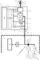
- a wallbox 1 is shown schematically, which is connected via a supply line 2 with a particular stationary battery storage system 3.
- a battery storage system 3 is an arrangement of batteries 5, 5a understood, which are connected directly and / or via a DC / DC converter 5b to the supply line 2.
- a system is formed in particular of a stationary battery memory 5, 5a, which is expediently designed as a high-voltage storage with a DC voltage of more than 100 volts.
- the battery storage system 3 indirectly via the battery 5a and the DC-DC converter 5a preferably electrically isolating and / or by direct connection of the battery 5 to the supply line 3 directly a DC voltage of 300 volts DC to 1000 volts DC, advantageously from 400 volts DC to 800 volts DC, in particular from 650 volts DC to 850 volts DC available.
- the wallbox 1 can z. B. on a wall, in particular an outer wall of a building 4, while the stationary battery storage system 3 is advantageously provided within a receiving space, a building 4 or the like.
- the supply line 2 connects the internal battery storage system 3 with the external wallbox 1.
- the battery storage system 3 may consist of an arrangement of a plurality of rechargeable batteries 5 and 5a, as shown schematically in the drawing.
- the batteries 5 are charged via an AC / DC converter 6 from a supply network 7.
- the batteries 5a are charged via the AC / DC converter 6 and the bidirectional DC / DC converter 5b.
- the utility network 7 may be a public network or a utility network of the building 4.
- the AC / DC converter 6 is designed so that, if required, energy can also be fed back from the battery storage system 3 into the supply network 7.
- the battery storage system 3 is connected via a communication module CM1 with a central controller CC in combination.
- the central controller CC can be a superordinate home controller; the central controller CC controls in particular the function of the battery storage system 3, z. B. the discharging and charging of the batteries 5, 5a.
- the wallbox 1 consists of a housing 10 which on the one hand has a supply connection 11 and on the other hand a charging connection 12.
- a mobile battery pack 8 is to be loaded in a vehicle 9, in particular is arranged in a motor vehicle, a delivery vehicle or a truck.
- the vehicle 9 is shown schematically as a motor vehicle.
- a wallbox controller WBC is provided which can be equipped with a display DP, an RFID reader, a WLAN module, a Bluetooth module, an NFC module or the like.
- a user ID can be made via a WLAN app, a Bluetooth connection, an NFC connection or the like.
- the wallbox controller is within the wallbox 1 in communication with a communication module CM2, which is connected to the supply line 2. Furthermore, the wallbox controller WBC is in communication with a particularly galvanically isolated DC / DC converter 13, which provides a charging voltage to a mobile battery pack 8 via a protection module 14 at the charging connection 12.
- a supply network 16 is provided with an operating voltage for the various electronic components of the wallbox 1 available.
- the particular two-core supply line 2 thus provides, on the one hand, the energy required for charging a mobile battery pack 8 and, on the other hand, the electrical energy required for electrical operation of the wallbox 1.
- the supply line 2 is designed, in particular, as a two-wire direct current line 20, which supplies a DC voltage of the battery storage system 3 to the wallbox 1.
- the battery storage system 3 is preferably a high-voltage accumulator with more than 100 volts, in particular a battery storage system with a DC voltage of 300 volts DC to 1000 volts DC.
- the battery storage system 3 has an output voltage of more than 300 volts DC, in particular an output voltage of 650 volts DC to 850 volts DC.
- the DC line 20 is designed in particular as a line with two current-carrying wires, in particular as a two-wire line, via the DC line 20 as the only electrical line connection between the battery storage system 3 and the Wallbox 1 on the one hand, the electrical energy for charging the mobile battery pack 8 and on the other hand, the electrical energy electrical operation of the wallbox 1 is supplied.
- This communication link 21 is in particular a powerline connection which establishes a data transmission by modulating a frequency signal on the DC line.
- the communication link 21 is preferably bidirectional.
- the supply line 2 is used as a DC line 20 and at the same time as a communication link 21, the installation cost of a wallbox 1 compared to conventional wall boxes is significantly reduced. Moreover, since a DC voltage of z. B. 650 volts to 850 volts is used, flows at a charging power of z. B. 20 kW only a small current of about 30 A or less, so that the required cable cross-section of the two-wire line can be made small.
- Communication modules CM1, CM2, CM3 and the wallbox controller WBC are connected to the DC line 20 for data transmission, wherein communication with the motor vehicle 9 connected to the charging connection 12 is established via the communication module CM3.
- the data connection can be designed so that all communication modules CM1, CM2, CM3 and the wallbox controller WBC can communicate with the central controller CC at will. All modules are over the second DC / DC converter supplied with the necessary operating voltage, which is preferably designed as a low voltage of less than 48 V in particular.
Applications Claiming Priority (1)
| Application Number | Priority Date | Filing Date | Title |
|---|---|---|---|
| DE102018003304.0A DE102018003304A1 (de) | 2018-04-20 | 2018-04-20 | Wallbox |
Publications (2)
| Publication Number | Publication Date |
|---|---|
| EP3556599A1 true EP3556599A1 (fr) | 2019-10-23 |
| EP3556599B1 EP3556599B1 (fr) | 2021-10-20 |
Family
ID=66217816
Family Applications (1)
| Application Number | Title | Priority Date | Filing Date |
|---|---|---|---|
| EP19169607.9A Active EP3556599B1 (fr) | 2018-04-20 | 2019-04-16 | Coffret mural |
Country Status (3)
| Country | Link |
|---|---|
| EP (1) | EP3556599B1 (fr) |
| DE (1) | DE102018003304A1 (fr) |
| ES (1) | ES2901196T3 (fr) |
Cited By (1)
| Publication number | Priority date | Publication date | Assignee | Title |
|---|---|---|---|---|
| DE102019128720A1 (de) * | 2019-10-24 | 2021-04-29 | Audi Ag | DC-Wallbox zur Ladung eines Elektrofahrzeuges |
Citations (3)
| Publication number | Priority date | Publication date | Assignee | Title |
|---|---|---|---|---|
| EP2110923A1 (fr) * | 2007-02-09 | 2009-10-21 | Kyushu Electric Power Co., Inc. | Chargeur |
| WO2011019855A1 (fr) * | 2009-08-11 | 2011-02-17 | Aerovironment, Inc. | Énergie stockée et équipement de charge |
| US20130020993A1 (en) * | 2011-07-18 | 2013-01-24 | Green Charge Networks Llc | Multi-Mode Electric Vehicle Charging Station |
-
2018
- 2018-04-20 DE DE102018003304.0A patent/DE102018003304A1/de not_active Withdrawn
-
2019
- 2019-04-16 EP EP19169607.9A patent/EP3556599B1/fr active Active
- 2019-04-16 ES ES19169607T patent/ES2901196T3/es active Active
Patent Citations (3)
| Publication number | Priority date | Publication date | Assignee | Title |
|---|---|---|---|---|
| EP2110923A1 (fr) * | 2007-02-09 | 2009-10-21 | Kyushu Electric Power Co., Inc. | Chargeur |
| WO2011019855A1 (fr) * | 2009-08-11 | 2011-02-17 | Aerovironment, Inc. | Énergie stockée et équipement de charge |
| US20130020993A1 (en) * | 2011-07-18 | 2013-01-24 | Green Charge Networks Llc | Multi-Mode Electric Vehicle Charging Station |
Cited By (2)
| Publication number | Priority date | Publication date | Assignee | Title |
|---|---|---|---|---|
| DE102019128720A1 (de) * | 2019-10-24 | 2021-04-29 | Audi Ag | DC-Wallbox zur Ladung eines Elektrofahrzeuges |
| DE102019128720B4 (de) | 2019-10-24 | 2024-03-21 | Audi Ag | DC-Wallbox zur Ladung eines Elektrofahrzeuges |
Also Published As
| Publication number | Publication date |
|---|---|
| ES2901196T8 (es) | 2022-04-06 |
| ES2901196T3 (es) | 2022-03-21 |
| DE102018003304A1 (de) | 2019-10-24 |
| EP3556599B1 (fr) | 2021-10-20 |
Similar Documents
| Publication | Publication Date | Title |
|---|---|---|
| EP2670624B1 (fr) | Dispositif de charge pour un accumulateur d'énergie électrique dans un véhicule automobile | |
| DE102019121108B3 (de) | Mobile Ladestation für ein Elektrofahrzeug | |
| EP2699446B1 (fr) | Dispositif de charge pour véhicule | |
| DE102013204256A1 (de) | Ladevorrichtung für ein Elektrofahrzeug | |
| DE102017130474A1 (de) | Transformatorvorrichtung für eine Ladestation für das elektrische Laden von Fahrzeugen mit wenigstens zwei Ladepunkten | |
| EP2279893A2 (fr) | Prise de chargement pour le chargement d'une voiture électrique dotée de moyens destinés à la communication entre une prise de chargement et un véhicule | |
| DE102013212219A1 (de) | Ladekabel zum Laden eines elektrischen Energiespeichers in einem Elektrofahrzeug | |
| DE102018212740A1 (de) | Ladestation für Elektroautos | |
| DE102015200960B4 (de) | Ladevorrichtung und Ladesystem | |
| EP1988612A2 (fr) | Dispositif de refroidissement mobile fonctionnant à l'aide d'un courant continu à basse tension | |
| EP2657063A1 (fr) | Dispositif de chargement | |
| EP3556599B1 (fr) | Coffret mural | |
| DE102018202260A1 (de) | Ladefahrzeug zum Laden eines elektrischen Energiespeichers eines Elektrofahrzeugs | |
| DE102017130497A1 (de) | Modulares Heimenergiesystem mit BUS-System und AC-Fahrzeugladeeinrichtung | |
| DE102020113210A1 (de) | Modulares externes AC-Ladegerät | |
| DE102014009088A1 (de) | Ladevorrichtung für einen elektrischen Energiespeicher | |
| DE102019204000A1 (de) | Ladevorrichtung zum Laden eines jeweiligen Energiespeichers von mehreren Kraftfahrzeugen | |
| AT514505B1 (de) | Energiespeichersystem | |
| DE102018208357A1 (de) | Adapter für das elektrische Laden eines Akkumulators eines Gerätes und Ladesystem hierfür | |
| DE102022003108A1 (de) | Transportable Ladestation zum Laden zumindest eines mobilen elektrischen Energiespeichers und Verfahren zum Betrieb einer Ladestation | |
| EP2279894A2 (fr) | Prise de chargement pour le chargement d'une voiture électrique dotée de moyens destinés l'intégration dans l'automate de bâtiment | |
| DE202013104820U1 (de) | Mobilstromversorger, der zonenaufgeteilt aufgeladen wird und in Serienschaltung entlädt | |
| DE102021105585A1 (de) | Externer Stromadapter für bidirektional-ladefähige Elektrofahrzeuge | |
| DE202016105623U1 (de) | Ladeeinrichtung für Powerbank | |
| EP2279895A2 (fr) | Prise de chargement pour le chargement d'une voiture électrique dotée de moyens destinés à l'intégration dans un réseau téléphonique |
Legal Events
| Date | Code | Title | Description |
|---|---|---|---|
| PUAI | Public reference made under article 153(3) epc to a published international application that has entered the european phase |
Free format text: ORIGINAL CODE: 0009012 |
|
| STAA | Information on the status of an ep patent application or granted ep patent |
Free format text: STATUS: THE APPLICATION HAS BEEN PUBLISHED |
|
| AK | Designated contracting states |
Kind code of ref document: A1 Designated state(s): AL AT BE BG CH CY CZ DE DK EE ES FI FR GB GR HR HU IE IS IT LI LT LU LV MC MK MT NL NO PL PT RO RS SE SI SK SM TR |
|
| AX | Request for extension of the european patent |
Extension state: BA ME |
|
| STAA | Information on the status of an ep patent application or granted ep patent |
Free format text: STATUS: REQUEST FOR EXAMINATION WAS MADE |
|
| 17P | Request for examination filed |
Effective date: 20200320 |
|
| RBV | Designated contracting states (corrected) |
Designated state(s): AL AT BE BG CH CY CZ DE DK EE ES FI FR GB GR HR HU IE IS IT LI LT LU LV MC MK MT NL NO PL PT RO RS SE SI SK SM TR |
|
| STAA | Information on the status of an ep patent application or granted ep patent |
Free format text: STATUS: EXAMINATION IS IN PROGRESS |
|
| STAA | Information on the status of an ep patent application or granted ep patent |
Free format text: STATUS: EXAMINATION IS IN PROGRESS |
|
| RAP1 | Party data changed (applicant data changed or rights of an application transferred) |
Owner name: ADS-TEC ENERGY GMBH |
|
| 17Q | First examination report despatched |
Effective date: 20201016 |
|
| GRAP | Despatch of communication of intention to grant a patent |
Free format text: ORIGINAL CODE: EPIDOSNIGR1 |
|
| STAA | Information on the status of an ep patent application or granted ep patent |
Free format text: STATUS: GRANT OF PATENT IS INTENDED |
|
| INTG | Intention to grant announced |
Effective date: 20210622 |
|
| GRAS | Grant fee paid |
Free format text: ORIGINAL CODE: EPIDOSNIGR3 |
|
| GRAA | (expected) grant |
Free format text: ORIGINAL CODE: 0009210 |
|
| STAA | Information on the status of an ep patent application or granted ep patent |
Free format text: STATUS: THE PATENT HAS BEEN GRANTED |
|
| AK | Designated contracting states |
Kind code of ref document: B1 Designated state(s): AL AT BE BG CH CY CZ DE DK EE ES FI FR GB GR HR HU IE IS IT LI LT LU LV MC MK MT NL NO PL PT RO RS SE SI SK SM TR |
|
| REG | Reference to a national code |
Ref country code: GB Ref legal event code: FG4D Free format text: NOT ENGLISH |
|
| REG | Reference to a national code |
Ref country code: CH Ref legal event code: EP |
|
| REG | Reference to a national code |
Ref country code: IE Ref legal event code: FG4D Free format text: LANGUAGE OF EP DOCUMENT: GERMAN |
|
| REG | Reference to a national code |
Ref country code: DE Ref legal event code: R096 Ref document number: 502019002531 Country of ref document: DE |
|
| REG | Reference to a national code |
Ref country code: AT Ref legal event code: REF Ref document number: 1439663 Country of ref document: AT Kind code of ref document: T Effective date: 20211115 |
|
| REG | Reference to a national code |
Ref country code: LT Ref legal event code: MG9D |
|
| REG | Reference to a national code |
Ref country code: NL Ref legal event code: MP Effective date: 20211020 |
|
| REG | Reference to a national code |
Ref country code: ES Ref legal event code: FG2A Ref document number: 2901196 Country of ref document: ES Kind code of ref document: T3 Effective date: 20220321 |
|
| PG25 | Lapsed in a contracting state [announced via postgrant information from national office to epo] |
Ref country code: RS Free format text: LAPSE BECAUSE OF FAILURE TO SUBMIT A TRANSLATION OF THE DESCRIPTION OR TO PAY THE FEE WITHIN THE PRESCRIBED TIME-LIMIT Effective date: 20211020 Ref country code: LT Free format text: LAPSE BECAUSE OF FAILURE TO SUBMIT A TRANSLATION OF THE DESCRIPTION OR TO PAY THE FEE WITHIN THE PRESCRIBED TIME-LIMIT Effective date: 20211020 Ref country code: FI Free format text: LAPSE BECAUSE OF FAILURE TO SUBMIT A TRANSLATION OF THE DESCRIPTION OR TO PAY THE FEE WITHIN THE PRESCRIBED TIME-LIMIT Effective date: 20211020 Ref country code: BG Free format text: LAPSE BECAUSE OF FAILURE TO SUBMIT A TRANSLATION OF THE DESCRIPTION OR TO PAY THE FEE WITHIN THE PRESCRIBED TIME-LIMIT Effective date: 20220120 |
|
| PG25 | Lapsed in a contracting state [announced via postgrant information from national office to epo] |
Ref country code: IS Free format text: LAPSE BECAUSE OF FAILURE TO SUBMIT A TRANSLATION OF THE DESCRIPTION OR TO PAY THE FEE WITHIN THE PRESCRIBED TIME-LIMIT Effective date: 20220220 Ref country code: SE Free format text: LAPSE BECAUSE OF FAILURE TO SUBMIT A TRANSLATION OF THE DESCRIPTION OR TO PAY THE FEE WITHIN THE PRESCRIBED TIME-LIMIT Effective date: 20211020 Ref country code: PT Free format text: LAPSE BECAUSE OF FAILURE TO SUBMIT A TRANSLATION OF THE DESCRIPTION OR TO PAY THE FEE WITHIN THE PRESCRIBED TIME-LIMIT Effective date: 20220221 Ref country code: PL Free format text: LAPSE BECAUSE OF FAILURE TO SUBMIT A TRANSLATION OF THE DESCRIPTION OR TO PAY THE FEE WITHIN THE PRESCRIBED TIME-LIMIT Effective date: 20211020 Ref country code: NO Free format text: LAPSE BECAUSE OF FAILURE TO SUBMIT A TRANSLATION OF THE DESCRIPTION OR TO PAY THE FEE WITHIN THE PRESCRIBED TIME-LIMIT Effective date: 20220120 Ref country code: NL Free format text: LAPSE BECAUSE OF FAILURE TO SUBMIT A TRANSLATION OF THE DESCRIPTION OR TO PAY THE FEE WITHIN THE PRESCRIBED TIME-LIMIT Effective date: 20211020 Ref country code: LV Free format text: LAPSE BECAUSE OF FAILURE TO SUBMIT A TRANSLATION OF THE DESCRIPTION OR TO PAY THE FEE WITHIN THE PRESCRIBED TIME-LIMIT Effective date: 20211020 Ref country code: HR Free format text: LAPSE BECAUSE OF FAILURE TO SUBMIT A TRANSLATION OF THE DESCRIPTION OR TO PAY THE FEE WITHIN THE PRESCRIBED TIME-LIMIT Effective date: 20211020 Ref country code: GR Free format text: LAPSE BECAUSE OF FAILURE TO SUBMIT A TRANSLATION OF THE DESCRIPTION OR TO PAY THE FEE WITHIN THE PRESCRIBED TIME-LIMIT Effective date: 20220121 |
|
| REG | Reference to a national code |
Ref country code: DE Ref legal event code: R097 Ref document number: 502019002531 Country of ref document: DE |
|
| PG25 | Lapsed in a contracting state [announced via postgrant information from national office to epo] |
Ref country code: SM Free format text: LAPSE BECAUSE OF FAILURE TO SUBMIT A TRANSLATION OF THE DESCRIPTION OR TO PAY THE FEE WITHIN THE PRESCRIBED TIME-LIMIT Effective date: 20211020 Ref country code: SK Free format text: LAPSE BECAUSE OF FAILURE TO SUBMIT A TRANSLATION OF THE DESCRIPTION OR TO PAY THE FEE WITHIN THE PRESCRIBED TIME-LIMIT Effective date: 20211020 Ref country code: RO Free format text: LAPSE BECAUSE OF FAILURE TO SUBMIT A TRANSLATION OF THE DESCRIPTION OR TO PAY THE FEE WITHIN THE PRESCRIBED TIME-LIMIT Effective date: 20211020 Ref country code: EE Free format text: LAPSE BECAUSE OF FAILURE TO SUBMIT A TRANSLATION OF THE DESCRIPTION OR TO PAY THE FEE WITHIN THE PRESCRIBED TIME-LIMIT Effective date: 20211020 Ref country code: DK Free format text: LAPSE BECAUSE OF FAILURE TO SUBMIT A TRANSLATION OF THE DESCRIPTION OR TO PAY THE FEE WITHIN THE PRESCRIBED TIME-LIMIT Effective date: 20211020 Ref country code: CZ Free format text: LAPSE BECAUSE OF FAILURE TO SUBMIT A TRANSLATION OF THE DESCRIPTION OR TO PAY THE FEE WITHIN THE PRESCRIBED TIME-LIMIT Effective date: 20211020 |
|
| PLBE | No opposition filed within time limit |
Free format text: ORIGINAL CODE: 0009261 |
|
| STAA | Information on the status of an ep patent application or granted ep patent |
Free format text: STATUS: NO OPPOSITION FILED WITHIN TIME LIMIT |
|
| 26N | No opposition filed |
Effective date: 20220721 |
|
| PG25 | Lapsed in a contracting state [announced via postgrant information from national office to epo] |
Ref country code: AL Free format text: LAPSE BECAUSE OF FAILURE TO SUBMIT A TRANSLATION OF THE DESCRIPTION OR TO PAY THE FEE WITHIN THE PRESCRIBED TIME-LIMIT Effective date: 20211020 |
|
| PG25 | Lapsed in a contracting state [announced via postgrant information from national office to epo] |
Ref country code: SI Free format text: LAPSE BECAUSE OF FAILURE TO SUBMIT A TRANSLATION OF THE DESCRIPTION OR TO PAY THE FEE WITHIN THE PRESCRIBED TIME-LIMIT Effective date: 20211020 |
|
| REG | Reference to a national code |
Ref country code: CH Ref legal event code: PL |
|
| REG | Reference to a national code |
Ref country code: BE Ref legal event code: MM Effective date: 20220430 |
|
| PG25 | Lapsed in a contracting state [announced via postgrant information from national office to epo] |
Ref country code: MC Free format text: LAPSE BECAUSE OF FAILURE TO SUBMIT A TRANSLATION OF THE DESCRIPTION OR TO PAY THE FEE WITHIN THE PRESCRIBED TIME-LIMIT Effective date: 20211020 Ref country code: LU Free format text: LAPSE BECAUSE OF NON-PAYMENT OF DUE FEES Effective date: 20220416 Ref country code: LI Free format text: LAPSE BECAUSE OF NON-PAYMENT OF DUE FEES Effective date: 20220430 Ref country code: CH Free format text: LAPSE BECAUSE OF NON-PAYMENT OF DUE FEES Effective date: 20220430 |
|
| PG25 | Lapsed in a contracting state [announced via postgrant information from national office to epo] |
Ref country code: BE Free format text: LAPSE BECAUSE OF NON-PAYMENT OF DUE FEES Effective date: 20220430 |
|
| PG25 | Lapsed in a contracting state [announced via postgrant information from national office to epo] |
Ref country code: IE Free format text: LAPSE BECAUSE OF NON-PAYMENT OF DUE FEES Effective date: 20220416 |
|
| P01 | Opt-out of the competence of the unified patent court (upc) registered |
Effective date: 20230523 |
|
| PGFP | Annual fee paid to national office [announced via postgrant information from national office to epo] |
Ref country code: IT Payment date: 20230426 Year of fee payment: 5 Ref country code: ES Payment date: 20230627 Year of fee payment: 5 Ref country code: DE Payment date: 20230420 Year of fee payment: 5 Ref country code: FR Payment date: 20230424 Year of fee payment: 5 |
|
| PGFP | Annual fee paid to national office [announced via postgrant information from national office to epo] |
Ref country code: GB Payment date: 20230419 Year of fee payment: 5 |
|
| PG25 | Lapsed in a contracting state [announced via postgrant information from national office to epo] |
Ref country code: HU Free format text: LAPSE BECAUSE OF FAILURE TO SUBMIT A TRANSLATION OF THE DESCRIPTION OR TO PAY THE FEE WITHIN THE PRESCRIBED TIME-LIMIT; INVALID AB INITIO Effective date: 20190416 |