EP3556599A1 - Wallbox - Google Patents
Wallbox Download PDFInfo
- Publication number
- EP3556599A1 EP3556599A1 EP19169607.9A EP19169607A EP3556599A1 EP 3556599 A1 EP3556599 A1 EP 3556599A1 EP 19169607 A EP19169607 A EP 19169607A EP 3556599 A1 EP3556599 A1 EP 3556599A1
- Authority
- EP
- European Patent Office
- Prior art keywords
- wallbox
- storage system
- battery storage
- line
- voltage
- Prior art date
- Legal status (The legal status is an assumption and is not a legal conclusion. Google has not performed a legal analysis and makes no representation as to the accuracy of the status listed.)
- Granted
Links
Images
Classifications
-
- B—PERFORMING OPERATIONS; TRANSPORTING
- B60—VEHICLES IN GENERAL
- B60L—PROPULSION OF ELECTRICALLY-PROPELLED VEHICLES; SUPPLYING ELECTRIC POWER FOR AUXILIARY EQUIPMENT OF ELECTRICALLY-PROPELLED VEHICLES; ELECTRODYNAMIC BRAKE SYSTEMS FOR VEHICLES IN GENERAL; MAGNETIC SUSPENSION OR LEVITATION FOR VEHICLES; MONITORING OPERATING VARIABLES OF ELECTRICALLY-PROPELLED VEHICLES; ELECTRIC SAFETY DEVICES FOR ELECTRICALLY-PROPELLED VEHICLES
- B60L53/00—Methods of charging batteries, specially adapted for electric vehicles; Charging stations or on-board charging equipment therefor; Exchange of energy storage elements in electric vehicles
- B60L53/10—Methods of charging batteries, specially adapted for electric vehicles; Charging stations or on-board charging equipment therefor; Exchange of energy storage elements in electric vehicles characterised by the energy transfer between the charging station and the vehicle
- B60L53/11—DC charging controlled by the charging station, e.g. mode 4
-
- B—PERFORMING OPERATIONS; TRANSPORTING
- B60—VEHICLES IN GENERAL
- B60L—PROPULSION OF ELECTRICALLY-PROPELLED VEHICLES; SUPPLYING ELECTRIC POWER FOR AUXILIARY EQUIPMENT OF ELECTRICALLY-PROPELLED VEHICLES; ELECTRODYNAMIC BRAKE SYSTEMS FOR VEHICLES IN GENERAL; MAGNETIC SUSPENSION OR LEVITATION FOR VEHICLES; MONITORING OPERATING VARIABLES OF ELECTRICALLY-PROPELLED VEHICLES; ELECTRIC SAFETY DEVICES FOR ELECTRICALLY-PROPELLED VEHICLES
- B60L53/00—Methods of charging batteries, specially adapted for electric vehicles; Charging stations or on-board charging equipment therefor; Exchange of energy storage elements in electric vehicles
- B60L53/30—Constructional details of charging stations
- B60L53/305—Communication interfaces
-
- B—PERFORMING OPERATIONS; TRANSPORTING
- B60—VEHICLES IN GENERAL
- B60L—PROPULSION OF ELECTRICALLY-PROPELLED VEHICLES; SUPPLYING ELECTRIC POWER FOR AUXILIARY EQUIPMENT OF ELECTRICALLY-PROPELLED VEHICLES; ELECTRODYNAMIC BRAKE SYSTEMS FOR VEHICLES IN GENERAL; MAGNETIC SUSPENSION OR LEVITATION FOR VEHICLES; MONITORING OPERATING VARIABLES OF ELECTRICALLY-PROPELLED VEHICLES; ELECTRIC SAFETY DEVICES FOR ELECTRICALLY-PROPELLED VEHICLES
- B60L53/00—Methods of charging batteries, specially adapted for electric vehicles; Charging stations or on-board charging equipment therefor; Exchange of energy storage elements in electric vehicles
- B60L53/30—Constructional details of charging stations
- B60L53/31—Charging columns specially adapted for electric vehicles
-
- H—ELECTRICITY
- H02—GENERATION; CONVERSION OR DISTRIBUTION OF ELECTRIC POWER
- H02J—ELECTRIC POWER NETWORKS; CIRCUIT ARRANGEMENTS OR SYSTEMS FOR SUPPLYING OR DISTRIBUTING ELECTRIC POWER; SYSTEMS FOR STORING ELECTRIC ENERGY
- H02J1/00—Circuit arrangements for DC mains or DC distribution networks
- H02J1/06—Two-wire DC power distribution systems
-
- Y—GENERAL TAGGING OF NEW TECHNOLOGICAL DEVELOPMENTS; GENERAL TAGGING OF CROSS-SECTIONAL TECHNOLOGIES SPANNING OVER SEVERAL SECTIONS OF THE IPC; TECHNICAL SUBJECTS COVERED BY FORMER USPC CROSS-REFERENCE ART COLLECTIONS [XRACs] AND DIGESTS
- Y02—TECHNOLOGIES OR APPLICATIONS FOR MITIGATION OR ADAPTATION AGAINST CLIMATE CHANGE
- Y02T—CLIMATE CHANGE MITIGATION TECHNOLOGIES RELATED TO TRANSPORTATION
- Y02T10/00—Road transport of goods or passengers
- Y02T10/60—Other road transportation technologies with climate change mitigation effect
- Y02T10/70—Energy storage systems for electromobility, e.g. batteries
-
- Y—GENERAL TAGGING OF NEW TECHNOLOGICAL DEVELOPMENTS; GENERAL TAGGING OF CROSS-SECTIONAL TECHNOLOGIES SPANNING OVER SEVERAL SECTIONS OF THE IPC; TECHNICAL SUBJECTS COVERED BY FORMER USPC CROSS-REFERENCE ART COLLECTIONS [XRACs] AND DIGESTS
- Y02—TECHNOLOGIES OR APPLICATIONS FOR MITIGATION OR ADAPTATION AGAINST CLIMATE CHANGE
- Y02T—CLIMATE CHANGE MITIGATION TECHNOLOGIES RELATED TO TRANSPORTATION
- Y02T10/00—Road transport of goods or passengers
- Y02T10/60—Other road transportation technologies with climate change mitigation effect
- Y02T10/7072—Electromobility specific charging systems or methods for batteries, ultracapacitors, supercapacitors or double-layer capacitors
-
- Y—GENERAL TAGGING OF NEW TECHNOLOGICAL DEVELOPMENTS; GENERAL TAGGING OF CROSS-SECTIONAL TECHNOLOGIES SPANNING OVER SEVERAL SECTIONS OF THE IPC; TECHNICAL SUBJECTS COVERED BY FORMER USPC CROSS-REFERENCE ART COLLECTIONS [XRACs] AND DIGESTS
- Y02—TECHNOLOGIES OR APPLICATIONS FOR MITIGATION OR ADAPTATION AGAINST CLIMATE CHANGE
- Y02T—CLIMATE CHANGE MITIGATION TECHNOLOGIES RELATED TO TRANSPORTATION
- Y02T90/00—Enabling technologies or technologies with a potential or indirect contribution to GHG emissions mitigation
- Y02T90/10—Technologies relating to charging of electric vehicles
- Y02T90/12—Electric charging stations
-
- Y—GENERAL TAGGING OF NEW TECHNOLOGICAL DEVELOPMENTS; GENERAL TAGGING OF CROSS-SECTIONAL TECHNOLOGIES SPANNING OVER SEVERAL SECTIONS OF THE IPC; TECHNICAL SUBJECTS COVERED BY FORMER USPC CROSS-REFERENCE ART COLLECTIONS [XRACs] AND DIGESTS
- Y02—TECHNOLOGIES OR APPLICATIONS FOR MITIGATION OR ADAPTATION AGAINST CLIMATE CHANGE
- Y02T—CLIMATE CHANGE MITIGATION TECHNOLOGIES RELATED TO TRANSPORTATION
- Y02T90/00—Enabling technologies or technologies with a potential or indirect contribution to GHG emissions mitigation
- Y02T90/10—Technologies relating to charging of electric vehicles
- Y02T90/14—Plug-in electric vehicles
-
- Y—GENERAL TAGGING OF NEW TECHNOLOGICAL DEVELOPMENTS; GENERAL TAGGING OF CROSS-SECTIONAL TECHNOLOGIES SPANNING OVER SEVERAL SECTIONS OF THE IPC; TECHNICAL SUBJECTS COVERED BY FORMER USPC CROSS-REFERENCE ART COLLECTIONS [XRACs] AND DIGESTS
- Y02—TECHNOLOGIES OR APPLICATIONS FOR MITIGATION OR ADAPTATION AGAINST CLIMATE CHANGE
- Y02T—CLIMATE CHANGE MITIGATION TECHNOLOGIES RELATED TO TRANSPORTATION
- Y02T90/00—Enabling technologies or technologies with a potential or indirect contribution to GHG emissions mitigation
- Y02T90/10—Technologies relating to charging of electric vehicles
- Y02T90/16—Information or communication technologies improving the operation of electric vehicles
Definitions
- the invention relates to a wallbox for charging mobile battery packs, in particular of motor vehicles.
- the wallbox is connected to a source of energy to provide a charging current via a supply line and, in turn, provides a charging port for electrical connection to the mobile battery pack of the vehicle.
- a voltage converter is provided, which adapts the voltage level of the energy source to a charging voltage of the battery pack.
- Another electrical connection is used to supply the wallbox with operating current.
- the wallbox controller exchanges data with the battery storage system via a communication connection.
- a well-known wallbox can be connected to a public utility network, due to the fixed AC voltage of the public network at high charging power, the supply lines to the wallbox must be correspondingly strongly dimensioned.
- an additional communication connection is usually installed as a wire connection or wireless connection between the wallbox and a central controller.
- the charging ports have powers of z. B. 20 kW, 40 kW or higher. This leads to correspondingly high currents in the supply line. Increasing charging power has led to higher charging voltages up to the high-voltage range of 300 volts to 1000 volts.
- a well-known wallbox has a high-voltage connection to provide the charging power and in addition a power supply from the public network of z. B. 230 volts AC.
- the invention has for its object to reduce installation costs for mounting a wallbox.
- the energy source is a battery storage system.
- the trained as a DC power supply line leads from the battery storage system to a DC voltage, which is in the high voltage range of 300 volts DC to 1000 volts DC, in particular 650 volts DC to 850 volts DC.
- the applied DC voltage is adjusted via a first DC / DC converter to a charging voltage of the mobile battery pack.
- the electrical supply line connected to the wallbox forms the only electrical supply line, from which on the one hand the operating current for the wallbox and on the other hand the charging current for the charging connection are fed. Additional electrical supply connections are eliminated.
- the DC line is connected within the housing of the wallbox with a second DC / DC converter, which lowers the high voltage of the DC line to the required operating voltage.
- the DC line for the electrical power supply of the wallbox and the communication connection between the wallbox controller and the battery storage system as a common electrical line, in particular form a common two-wire line.
- the DC line is connected to at least one communication module, which establishes the communication with the Wallboxcontroller.
- a communication module is provided, which establishes a data connection via the DC line and the battery storage system and advantageous to a central controller.
- the communication connection via the DC line is designed in particular as a powerline data connection.
- a battery storage system is an arrangement of batteries that are connected directly and / or via a DC / DC converter to the supply line.
- Such a system forms in particular a stationary battery storage, which is expediently designed as a high-voltage storage with a DC voltage of more than 100 volts.
- the battery storage system provides via a DC / DC converter directly or indirectly to the battery, a DC voltage of 300 volts DC to 1000 volts DC, advantageously from 400 volts DC to 800 volts DC, in particular from 650 volts DC to 850 volts DC ready.
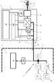
- a wallbox 1 is shown schematically, which is connected via a supply line 2 with a particular stationary battery storage system 3.
- a battery storage system 3 is an arrangement of batteries 5, 5a understood, which are connected directly and / or via a DC / DC converter 5b to the supply line 2.
- a system is formed in particular of a stationary battery memory 5, 5a, which is expediently designed as a high-voltage storage with a DC voltage of more than 100 volts.
- the battery storage system 3 indirectly via the battery 5a and the DC-DC converter 5a preferably electrically isolating and / or by direct connection of the battery 5 to the supply line 3 directly a DC voltage of 300 volts DC to 1000 volts DC, advantageously from 400 volts DC to 800 volts DC, in particular from 650 volts DC to 850 volts DC available.
- the wallbox 1 can z. B. on a wall, in particular an outer wall of a building 4, while the stationary battery storage system 3 is advantageously provided within a receiving space, a building 4 or the like.
- the supply line 2 connects the internal battery storage system 3 with the external wallbox 1.
- the battery storage system 3 may consist of an arrangement of a plurality of rechargeable batteries 5 and 5a, as shown schematically in the drawing.
- the batteries 5 are charged via an AC / DC converter 6 from a supply network 7.
- the batteries 5a are charged via the AC / DC converter 6 and the bidirectional DC / DC converter 5b.
- the utility network 7 may be a public network or a utility network of the building 4.
- the AC / DC converter 6 is designed so that, if required, energy can also be fed back from the battery storage system 3 into the supply network 7.
- the battery storage system 3 is connected via a communication module CM1 with a central controller CC in combination.
- the central controller CC can be a superordinate home controller; the central controller CC controls in particular the function of the battery storage system 3, z. B. the discharging and charging of the batteries 5, 5a.
- the wallbox 1 consists of a housing 10 which on the one hand has a supply connection 11 and on the other hand a charging connection 12.
- a mobile battery pack 8 is to be loaded in a vehicle 9, in particular is arranged in a motor vehicle, a delivery vehicle or a truck.
- the vehicle 9 is shown schematically as a motor vehicle.
- a wallbox controller WBC is provided which can be equipped with a display DP, an RFID reader, a WLAN module, a Bluetooth module, an NFC module or the like.
- a user ID can be made via a WLAN app, a Bluetooth connection, an NFC connection or the like.
- the wallbox controller is within the wallbox 1 in communication with a communication module CM2, which is connected to the supply line 2. Furthermore, the wallbox controller WBC is in communication with a particularly galvanically isolated DC / DC converter 13, which provides a charging voltage to a mobile battery pack 8 via a protection module 14 at the charging connection 12.
- a supply network 16 is provided with an operating voltage for the various electronic components of the wallbox 1 available.
- the particular two-core supply line 2 thus provides, on the one hand, the energy required for charging a mobile battery pack 8 and, on the other hand, the electrical energy required for electrical operation of the wallbox 1.
- the supply line 2 is designed, in particular, as a two-wire direct current line 20, which supplies a DC voltage of the battery storage system 3 to the wallbox 1.
- the battery storage system 3 is preferably a high-voltage accumulator with more than 100 volts, in particular a battery storage system with a DC voltage of 300 volts DC to 1000 volts DC.
- the battery storage system 3 has an output voltage of more than 300 volts DC, in particular an output voltage of 650 volts DC to 850 volts DC.
- the DC line 20 is designed in particular as a line with two current-carrying wires, in particular as a two-wire line, via the DC line 20 as the only electrical line connection between the battery storage system 3 and the Wallbox 1 on the one hand, the electrical energy for charging the mobile battery pack 8 and on the other hand, the electrical energy electrical operation of the wallbox 1 is supplied.
- This communication link 21 is in particular a powerline connection which establishes a data transmission by modulating a frequency signal on the DC line.
- the communication link 21 is preferably bidirectional.
- the supply line 2 is used as a DC line 20 and at the same time as a communication link 21, the installation cost of a wallbox 1 compared to conventional wall boxes is significantly reduced. Moreover, since a DC voltage of z. B. 650 volts to 850 volts is used, flows at a charging power of z. B. 20 kW only a small current of about 30 A or less, so that the required cable cross-section of the two-wire line can be made small.
- Communication modules CM1, CM2, CM3 and the wallbox controller WBC are connected to the DC line 20 for data transmission, wherein communication with the motor vehicle 9 connected to the charging connection 12 is established via the communication module CM3.
- the data connection can be designed so that all communication modules CM1, CM2, CM3 and the wallbox controller WBC can communicate with the central controller CC at will. All modules are over the second DC / DC converter supplied with the necessary operating voltage, which is preferably designed as a low voltage of less than 48 V in particular.
Landscapes
- Engineering & Computer Science (AREA)
- Power Engineering (AREA)
- Transportation (AREA)
- Mechanical Engineering (AREA)
- Charge And Discharge Circuits For Batteries Or The Like (AREA)
- Electric Propulsion And Braking For Vehicles (AREA)
Abstract
Description
- Die Erfindung betrifft eine Wallbox zum Aufladen von mobilen Akkupacks insbesondere von Kraftfahrzeugen. Die Wallbox wird zur Bereitstellung eines Ladestroms über eine Versorgungsleitung an eine Energiequelle angeschlossen und stellt ihrerseits einen Ladeanschluss zur elektrischen Verbindung mit dem mobilen Akkupack des Fahrzeugs bereit. Im Gehäuse der Wallbox ist ein Spannungswandler vorgesehen, der das Spannungsniveau der Energiequelle an eine Ladespannung des Akkupacks anpasst. Über einen weiteren elektrischen Anschluss wird die Wallbox mit Betriebsstrom versorgt. Über eine Kommunikationsverbindung tauscht der Wallboxcontroller mit dem Batteriespeichersystem Daten aus.
- Eine bekannte Wallbox kann an ein öffentliches Versorgungsnetz angeschlossen sein, wobei aufgrund der festliegenden Wechselspannung des öffentlichen Netzes bei hohen Ladeleistungen die Versorgungsleitungen zur Wallbox entsprechend stark dimensioniert sein müssen. Darüber hinaus wird meist eine zusätzliche Kommunikationsverbindung als Drahtverbindung oder drahtlose Verbindung zwischen der Wallbox und einer zentralen Steuerung installiert.
- Da die Ladezeiten immer kürzer werden sollen, verfügen die Ladeanschlüsse über Leistungen von z. B. 20 kW, 40 kW oder höher. Dies führt zu entsprechend hohen Strömen in der Versorgungsleitung. Wachsende Ladeleistungen haben zu höheren Ladespannungen bis in den Hochvoltbereich von 300 Volt bis 1000 Volt geführt. Eine bekannte Wallbox weist einen Hochvoltanschluss zur Bereitstellung der Ladeleistung und zusätzlich eine Spannungsversorgung aus dem öffentlichen Netz von z. B. 230 Volt AC auf.
- Der Erfindung liegt die Aufgabe zugrunde, den Installationsaufwand zur Montage einer Wallbox zu reduzieren.
- Die Aufgabe wird dadurch gelöst, dass die Energiequelle ein Batteriespeichersystem ist. Die als Gleichstromleitung ausgebildete Versorgungsleitung führt aus dem Batteriespeichersystem eine Gleichspannung zu, die im Hochvoltbereich von 300 Volt DC bis 1000 Volt DC, insbesondere 650 Volt DC bis 850 Volt DC liegt. Innerhalb der Wallbox wird die anliegende Gleichspannung über einen ersten DC/DC-Wandler an eine Ladespannung des mobilen Akkupacks angepasst. Die an die Wallbox angeschlossene elektrische Versorgungsleitung bildet die einzige elektrische Versorgungsleitung, aus der einerseits der Betriebsstrom für die Wallbox und andererseits der Ladestrom für den Ladeanschluss gespeist sind. Weitere elektrische Versorgungsanschlüsse entfallen.
- Zur Bereitstellung der Betriebsspannung für die Komponenten der Wallbox ist die Gleichstromleitung innerhalb des Gehäuses der Wallbox mit einem zweiten DC/DC-Wandler verbunden, der die Hochvoltspannung der Gleichstromleitung auf die erforderliche Betriebsspannung absenkt.
- In Weiterbildung der Erfindung ist vorgesehen, die Gleichstromleitung zur elektrischen Energieversorgung der Wallbox und die Kommunikationsverbindung zwischen dem Wallboxcontroller und dem Batteriespeichersystem als gemeinsame elektrische Leitung, insbesondere als gemeinsame Zweidrahtleitung auszubilden. Dadurch ist lediglich ein einfaches Kabel zur Installation der Wallbox nötig, welches einerseits die Energie von dem Batteriespeichersystem zur Wallbox führt und andererseits eine Kommunikationsverbindung zwischen der Wallbox und dem Batteriespeichersystem herstellt.
- Innerhalb des Gehäuses der Wallbox ist die Gleichstromleitung mit zumindest einem Kommunikationsmodul verbunden, welches die Kommunikation mit dem Wallboxcontroller herstellt. Innerhalb des Batteriespeichersystems ist ein Kommunikationsmodul vorgesehen, welches eine Datenverbindung über die Gleichstromleitung und dem Batteriespeichersystem sowie vorteilhaft zu einer zentralen Steuerung herstellt.
- Die Kommunikationsverbindung über die Gleichstromleitung ist insbesondere als Powerline-Datenverbindung ausgebildet.
- Als Batteriespeichersystem wird eine Anordnung aus Batterien verstanden, die unmittelbar und/oder über einen DC/DC-Wandler an die Versorgungsleitung angeschlossen sind. Ein derartiges System bildet insbesondere einen stationären Batteriespeicher, der zweckmäßig als Hochvoltspeicher mit einer Gleichspannung von mehr als 100 Volt ausgebildet ist. Das Batteriespeichersystem stellt über einen DC/DC-Wandler mittelbar oder unmittelbar an der Batterie eine Gleichspannung von 300 Volt DC bis 1000 Volt DC, vorteilhaft von 400 Volt DC bis 800 Volt DC, insbesondere von 650 Volt DC bis 850 Volt DC bereit.
- Weitere Merkmale der Erfindung ergeben sich aus den weiteren Ansprüchen, der Beschreibung und der Zeichnung, in der ein schematisches Ausführungsbeispiel der Erfindung dargestellt ist, welches nachfolgend im Einzelnen beschrieben ist.
- In der Zeichnung ist schematisch der Aufbau einer Wallbox 1 wiedergegeben, die über eine Versorgungsleitung 2 mit einem insbesondere stationären Batteriespeichersystem 3 verbunden ist.
- Als Batteriespeichersystem 3 wird eine Anordnung aus Batterien 5, 5a verstanden, die unmittelbar und/oder über einen DC/DC-Wandler 5b an die Versorgungsleitung 2 angeschlossen sind. Ein derartiges System ist insbesondere aus einem stationären Batteriespeicher 5, 5a gebildet, der zweckmäßig als Hochvoltspeicher mit einer Gleichspannung von mehr als 100 Volt ausgebildet ist. Das Batteriespeichersystem 3 stellt über die Batterie 5a und den vorzugsweise galvanisch trennenden DC/DC-Wandler 5a mittelbar und/oder durch direkten Anschluss der Batterie 5 an die Versorgungsleitung 3 unmittelbar eine Gleichspannung von 300 Volt DC bis 1000 Volt DC, vorteilhaft von 400 Volt DC bis 800 Volt DC, insbesondere von 650 Volt DC bis 850 Volt DC zur Verfügung.
- Die Wallbox 1 kann z. B. an einer Wand, insbesondere einer Außenwand eines Gebäudes 4 angeordnet sein, während das stationäre Batteriespeichersystem 3 vorteilhaft innerhalb eines Aufnahmeraums, eines Gebäudes 4 oder dergleichen vorgesehen ist. Die Versorgungsleitung 2 verbindet dabei das innenliegende Batteriespeichersystem 3 mit der außenliegenden Wallbox 1.
- Das Batteriespeichersystem 3 kann aus einer Anordnung von mehreren wiederaufladbaren Batterien 5 und 5a bestehen, wie sie in der Zeichnung schematisch dargestellt sind. Die Batterien 5 werden über einen AC/DC-Wandler 6 aus einem Versorgungsnetz 7 geladen. Die Batterien 5a werden über den AC/DC-Wandler 6 und den bidirektionalen DC/DC-Wandler 5b aufgeladen. Das Versorgungsnetz 7 kann ein öffentliches Netz oder ein Versorgungsnetz des Gebäudes 4 sein. Vorzugsweise ist der AC/DC-Wandler 6 dazu ausgelegt, dass bei Bedarf auch Energie aus dem Batteriespeichersystem 3 in das Versorgungsnetz 7 zurückgespeist werden kann.
- Der Batteriespeichersystem 3 steht über ein Kommunikationsmodul CM1 mit einer zentralen Steuerung CC in Verbindung. Die zentrale Steuerung CC kann eine übergeordnete Haussteuerung sein; die zentrale Steuerung CC steuert insbesondere die Funktion des Batteriespeichersystems 3, z. B. das Entladen und das Laden der Batterien 5, 5a.
- Die Wallbox 1 besteht aus einem Gehäuse 10, das einerseits einen Versorgungsanschluss 11 und andererseits einen Ladeanschluss 12 aufweist. Über den Ladeanschluss 12 ist ein mobiler Akkupack 8 zu laden, der in einem Fahrzeug 9, insbesondere in einem Kraftfahrzeug, einem Lieferfahrzeug oder einem Lastkraftwagen angeordnet ist. In der Zeichnung ist das Fahrzeug 9 schematisch als Kraftfahrzeug wiedergegeben.
- Im Gehäuse 10 der Wallbox 1 ist ein Wallboxcontroller WBC vorgesehen, der mit einem Display DP, einem RFID-Leser, einem WLAN-Modul, einem Bluetooth-Modul, einem NFC-Modul oder dergleichen ausgestattet sein kann. So kann über eine WLAN-App, eine Bluetooth-Verbindung, eine NFC-Verbindung oder dgl. eine Nutzerkennung erfolgen. Eine Bedienung der Wallbox durch einen Benutzer ist erst nach dessen eindeutiger Identifizierung möglich.
- Der Wallboxcontroller steht innerhalb der Wallbox 1 in Kommunikationsverbindung mit einem Kommunikationsmodul CM2, welches an die Versorgungsleitung 2 angeschlossen ist. Ferner steht der Wallboxcontroller WBC in Kommunikationsverbindung mit einem insbesondere galvanisch getrennten DC/DC-Wandler 13, der über ein Schutzmodul 14 am Ladeanschluss 12 eine Ladespannung einem mobilen Akkupack 8 zur Verfügung stellt.
- Über einen weiteren insbesondere galvanisch trennenden DC/DC-Wandler, der an die Versorgungsleitung 2 angeschlossen ist, wird ein Versorgungsnetz 16 mit einer Betriebsspannung für die verschiedenen elektronischen Baugruppen der Wallbox 1 zur Verfügung gestellt.
- Die insbesondere zweiadrige Versorgungsleitung 2 stellt somit einerseits die zum Laden eines mobilen Akkupacks 8 notwendige Energie und andererseits die zum elektrischen Betrieb der Wallbox 1 erforderliche elektrische Energie zur Verfügung.
- Die Versorgungsleitung 2 ist insbesondere als zweiadrige Gleichstromleitung 20 ausgebildet, die eine Gleichspannung des Batteriespeichersystems 3 der Wallbox 1 zuführt. Das Batteriespeichersystem 3 ist bevorzugt ein Hochvoltspeicher mit mehr als 100 Volt, insbesondere ein Batteriespeichersystem mit einer Gleichspannung von 300 Volt DC bis 1000 Volt DC. Vorzugsweise hat das Batteriespeichersystem 3 eine Ausgangsspannung von mehr als 300 Volt DC, insbesondere eine Ausgangsspannung von 650 Volt DC bis 850 Volt DC.
- Die Gleichstromleitung 20 ist insbesondere als Leitung mit zwei stromführenden Adern, insbesondere als Zweidrahtleitung ausgelegt, wobei über die Gleichstromleitung 20 als einzige elektrische Leitungsverbindung zwischen dem Batteriespeichersystem 3 und der Wallbox 1 einerseits die elektrische Energie zum Laden des mobilen Akkupacks 8 und andererseits die elektrische Energie zum elektrischen Betrieb der Wallbox 1 zugeführt wird.
- Zweckmäßig ist vorgesehen, über die Gleichstromleitung 2 zugleich eine Drahtverbindung als Kommunikationsverbindung zwischen der Wallbox 1 und dem Batteriespeichersystem 3 herzustellen. Diese Kommunikationsverbindung 21 ist insbesondere eine Powerline-Verbindung, die eine Datenübertragung durch Aufmodulieren eines Frequenzsignals auf der Gleichstromleitung herstellt. Die Kommunikationsverbindung 21 ist vorzugsweise bidirektional.
- Da die Versorgungsleitung 2 als Gleichstromleitung 20 und zugleich als Kommunikationsverbindung 21 genutzt wird, ist der Installationsaufwand einer Wallbox 1 gegenüber herkömmlichen Wallboxen signifikant reduziert. Da darüber hinaus vorteilhaft eine Gleichspannung von z. B. 650 Volt bis 850 Volt genutzt wird, fließt bei einer Ladeleistung von z. B. 20 kW ein nur geringer Strom von ca. 30 A oder weniger, so dass der erforderliche Leitungsquerschnitt der Zweidrahtleitung klein ausgelegt werden kann. An die Gleichstromleitung 20 sind zur Datenübermittlung Kommunikationsmodule CM1, CM2, CM3 und der Wallboxcontroller WBC angeschlossen, wobei über das Kommunikationsmodul CM3 eine Kommunikation mit dem an dem Ladeanschluss 12 angeschlossenen Kraftfahrzeug 9 hergestellt ist. Die Datenverbindung kann so ausgelegt sein, dass alle Kommunikationsmodule CM1, CM2, CM3 und der Wallboxcontroller WBC mit der zentralen Steuerung CC beliebig kommunizieren können. Alle Module werden über den zweiten DC/DC-Wandler mit der notwendigen Betriebsspannung versorgt, die vorzugsweise als Kleinspannung von insbesondere weniger als 48 V ausgelegt ist.
Claims (10)
- Wallbox zum Aufladen von mobilen Akkupacks aus einem Batteriespeichersystem (3), insbesondere zum Laden von mobilen Akkupacks (8) in Fahrzeugen (9), mit in einem Gehäuse (10) der Wallbox (1) angeordnetem Wallboxcontroller (WBC), wobei das Batteriespeichersystem (3) mit einer Versorgungsleitung (2) an die Wallbox (1) angeschlossen ist und die Wallbox (1) einen Ladeanschluss (12) zur elektrischen Verbindung mit dem mobilen Akkupack (8) aufweist, und mit einem in dem Gehäuse (10) der Wallbox (1) angeordneten DC/DC-Wandler (13), der eine über die Versorgungsleitung (2) aus dem Batteriespeichersystem (3) zugeführte Gleichspannung an eine Ladespannung des mobilen Akkupacks (8) anpasst, sowie mit einer Kommunikationsverbindung (21) zwischen dem Wallboxcontroller (WBC) und dem Batteriespeichersystem (3), wobei die einzige an die Wallbox (1) angeschlossene elektrische Versorgungsleitung (2) eine Gleichstromleitung (20) ist, aus der der Betriebsstrom für die Wallbox (1) einerseits und der Ladestrom für den Ladeanschluss (12) andererseits gespeist ist.
- Wallbox nach Anspruch 1,
dadurch gekennzeichnet, dass die Gleichstromleitung (20) innerhalb des Gehäuses (10) der Wallbox (1) mit einem zweiten DC/DC-Wandler (15) zur Bereitstellung einer Betriebsspannung (16) für die Wallbox (1) verbunden ist. - Wallbox nach Anspruch 1,
dadurch gekennzeichnet, dass die Gleichstromleitung (20) zur elektrischen Energieversorgung und die Kommunikationsverbindung (21) zwischen dem Wallboxcontroller (WBC) und dem Batteriespeichersystem (3) als gemeinsame Leitung ausgebildet sind. - Wallbox nach Anspruch 3,
dadurch gekennzeichnet, dass die gemeinsame die Gleichstromleitung (20) eine Zweidrahtleitung ist. - Wallbox nach Anspruch 3,
dadurch gekennzeichnet, dass die Gleichstromleitung (20) innerhalb des Gehäuses (10) der Wallbox (1) mit einem Kommunikationsmodul (CM2) verbunden ist. - Wallbox nach Anspruch 3,
dadurch gekennzeichnet, dass ein innerhalb des Batteriespeichersystems (3) vorgesehenes Kommunikationsmodul (CM1) mit der Gleichstromleitung (20) verbunden ist. - Wallbox nach Anspruch 3,
dadurch gekennzeichnet, dass die Kommunikationsverbindung (21) eine Powerline Verbindung ist. - Wallbox nach Anspruch 1,
dadurch gekennzeichnet, dass das Batteriespeichersystem (3) ein stationäres Batteriespeichersystem ist. - Wallbox nach Anspruch 1,
dadurch gekennzeichnet, dass das Batteriespeichersystem (3) einen Hochvolt-Speicher mit einer Gleichspannung von mehr als 300 Volt umfasst. - Wallbox nach Anspruch 9,
dadurch gekennzeichnet, dass das Batteriespeichersystem (3) eine Gleichspannung im Bereich von 300 Volt bis 1000 Volt, insbesondere von 400 Volt bis 800 Volt aufweist.
Applications Claiming Priority (1)
| Application Number | Priority Date | Filing Date | Title |
|---|---|---|---|
| DE102018003304.0A DE102018003304A1 (de) | 2018-04-20 | 2018-04-20 | Wallbox |
Publications (2)
| Publication Number | Publication Date |
|---|---|
| EP3556599A1 true EP3556599A1 (de) | 2019-10-23 |
| EP3556599B1 EP3556599B1 (de) | 2021-10-20 |
Family
ID=66217816
Family Applications (1)
| Application Number | Title | Priority Date | Filing Date |
|---|---|---|---|
| EP19169607.9A Active EP3556599B1 (de) | 2018-04-20 | 2019-04-16 | Wallbox |
Country Status (3)
| Country | Link |
|---|---|
| EP (1) | EP3556599B1 (de) |
| DE (1) | DE102018003304A1 (de) |
| ES (1) | ES2901196T3 (de) |
Cited By (1)
| Publication number | Priority date | Publication date | Assignee | Title |
|---|---|---|---|---|
| DE102019128720A1 (de) * | 2019-10-24 | 2021-04-29 | Audi Ag | DC-Wallbox zur Ladung eines Elektrofahrzeuges |
Citations (3)
| Publication number | Priority date | Publication date | Assignee | Title |
|---|---|---|---|---|
| EP2110923A1 (de) * | 2007-02-09 | 2009-10-21 | Kyushu Electric Power Co., Inc. | Ladegerät |
| WO2011019855A1 (en) * | 2009-08-11 | 2011-02-17 | Aerovironment, Inc. | Stored energy and charging appliance |
| US20130020993A1 (en) * | 2011-07-18 | 2013-01-24 | Green Charge Networks Llc | Multi-Mode Electric Vehicle Charging Station |
-
2018
- 2018-04-20 DE DE102018003304.0A patent/DE102018003304A1/de not_active Withdrawn
-
2019
- 2019-04-16 EP EP19169607.9A patent/EP3556599B1/de active Active
- 2019-04-16 ES ES19169607T patent/ES2901196T3/es active Active
Patent Citations (3)
| Publication number | Priority date | Publication date | Assignee | Title |
|---|---|---|---|---|
| EP2110923A1 (de) * | 2007-02-09 | 2009-10-21 | Kyushu Electric Power Co., Inc. | Ladegerät |
| WO2011019855A1 (en) * | 2009-08-11 | 2011-02-17 | Aerovironment, Inc. | Stored energy and charging appliance |
| US20130020993A1 (en) * | 2011-07-18 | 2013-01-24 | Green Charge Networks Llc | Multi-Mode Electric Vehicle Charging Station |
Cited By (2)
| Publication number | Priority date | Publication date | Assignee | Title |
|---|---|---|---|---|
| DE102019128720A1 (de) * | 2019-10-24 | 2021-04-29 | Audi Ag | DC-Wallbox zur Ladung eines Elektrofahrzeuges |
| DE102019128720B4 (de) | 2019-10-24 | 2024-03-21 | Audi Ag | DC-Wallbox zur Ladung eines Elektrofahrzeuges |
Also Published As
| Publication number | Publication date |
|---|---|
| ES2901196T3 (es) | 2022-03-21 |
| DE102018003304A1 (de) | 2019-10-24 |
| EP3556599B1 (de) | 2021-10-20 |
| ES2901196T8 (es) | 2022-04-06 |
Similar Documents
| Publication | Publication Date | Title |
|---|---|---|
| EP2670624B1 (de) | Ladevorrichtung für einen elektrischen energiespeicher in einem kraftfahrzeug | |
| EP2699446B1 (de) | Fahrzeugladevorrichtung | |
| EP1988612A2 (de) | Mit Niedervoltgleichstrom betriebene mobile Kühleinrichtung | |
| DE102013204256A1 (de) | Ladevorrichtung für ein Elektrofahrzeug | |
| DE102015200960B4 (de) | Ladevorrichtung und Ladesystem | |
| DE102020113210A1 (de) | Modulares externes AC-Ladegerät | |
| EP2279893A2 (de) | Lade-Steckdose zur Aufladung eines Elektroautos, mit Mitteln zur Kommunikation zwischen Lade-Steckdose und Fahrzeug | |
| DE102019204000A1 (de) | Ladevorrichtung zum Laden eines jeweiligen Energiespeichers von mehreren Kraftfahrzeugen | |
| EP2657063A1 (de) | Ladevorrichtung | |
| EP2601070A2 (de) | Verfahren zum laden zumindest eines energiespeichers eines elektrofahrzeugs | |
| DE102020204625B4 (de) | DC/DC-Wandler-Einrichtung sowie Steuer/Regel-System für ein Stromnetz | |
| DE102018202260A1 (de) | Ladefahrzeug zum Laden eines elektrischen Energiespeichers eines Elektrofahrzeugs | |
| EP3556599B1 (de) | Wallbox | |
| DE102014009088A1 (de) | Ladevorrichtung für einen elektrischen Energiespeicher | |
| DE102022003108A1 (de) | Transportable Ladestation zum Laden zumindest eines mobilen elektrischen Energiespeichers und Verfahren zum Betrieb einer Ladestation | |
| DE102018208357A1 (de) | Adapter für das elektrische Laden eines Akkumulators eines Gerätes und Ladesystem hierfür | |
| DE102021121127A1 (de) | Verfahren zum Betreiben eines Netzmanagementsystems für ein lokales Energienetz, Computerprogrammprodukt sowie Netzmanagementsystem | |
| DE202013104052U1 (de) | Kompakte USB-Doppelsteckdose mit eingebautem Abwärtswandler | |
| DE202016105623U1 (de) | Ladeeinrichtung für Powerbank | |
| AT514505B1 (de) | Energiespeichersystem | |
| DE102020104736A1 (de) | Kraftfahrzeug umfassend eine Ladeeinrichtung | |
| WO2023209030A2 (de) | Energieversorgungssystem und verfahren zum betrieb eines energieversorgungssystems | |
| DE102022112277A1 (de) | Versorgungseinheit zur Wandmontage | |
| EP2279894A2 (de) | Lade-Steckdose zur Aufladung eines Elektroautos, mit Mitteln zur Einbindung in die Gebäudeautomaten | |
| DE102021105585A1 (de) | Externer Stromadapter für bidirektional-ladefähige Elektrofahrzeuge |
Legal Events
| Date | Code | Title | Description |
|---|---|---|---|
| PUAI | Public reference made under article 153(3) epc to a published international application that has entered the european phase |
Free format text: ORIGINAL CODE: 0009012 |
|
| STAA | Information on the status of an ep patent application or granted ep patent |
Free format text: STATUS: THE APPLICATION HAS BEEN PUBLISHED |
|
| AK | Designated contracting states |
Kind code of ref document: A1 Designated state(s): AL AT BE BG CH CY CZ DE DK EE ES FI FR GB GR HR HU IE IS IT LI LT LU LV MC MK MT NL NO PL PT RO RS SE SI SK SM TR |
|
| AX | Request for extension of the european patent |
Extension state: BA ME |
|
| STAA | Information on the status of an ep patent application or granted ep patent |
Free format text: STATUS: REQUEST FOR EXAMINATION WAS MADE |
|
| 17P | Request for examination filed |
Effective date: 20200320 |
|
| RBV | Designated contracting states (corrected) |
Designated state(s): AL AT BE BG CH CY CZ DE DK EE ES FI FR GB GR HR HU IE IS IT LI LT LU LV MC MK MT NL NO PL PT RO RS SE SI SK SM TR |
|
| STAA | Information on the status of an ep patent application or granted ep patent |
Free format text: STATUS: EXAMINATION IS IN PROGRESS |
|
| RAP1 | Party data changed (applicant data changed or rights of an application transferred) |
Owner name: ADS-TEC ENERGY GMBH |
|
| 17Q | First examination report despatched |
Effective date: 20201016 |
|
| GRAP | Despatch of communication of intention to grant a patent |
Free format text: ORIGINAL CODE: EPIDOSNIGR1 |
|
| STAA | Information on the status of an ep patent application or granted ep patent |
Free format text: STATUS: GRANT OF PATENT IS INTENDED |
|
| INTG | Intention to grant announced |
Effective date: 20210622 |
|
| GRAS | Grant fee paid |
Free format text: ORIGINAL CODE: EPIDOSNIGR3 |
|
| GRAA | (expected) grant |
Free format text: ORIGINAL CODE: 0009210 |
|
| STAA | Information on the status of an ep patent application or granted ep patent |
Free format text: STATUS: THE PATENT HAS BEEN GRANTED |
|
| AK | Designated contracting states |
Kind code of ref document: B1 Designated state(s): AL AT BE BG CH CY CZ DE DK EE ES FI FR GB GR HR HU IE IS IT LI LT LU LV MC MK MT NL NO PL PT RO RS SE SI SK SM TR |
|
| REG | Reference to a national code |
Ref country code: GB Ref legal event code: FG4D Free format text: NOT ENGLISH |
|
| REG | Reference to a national code |
Ref country code: CH Ref legal event code: EP |
|
| REG | Reference to a national code |
Ref country code: IE Ref legal event code: FG4D Free format text: LANGUAGE OF EP DOCUMENT: GERMAN |
|
| REG | Reference to a national code |
Ref country code: DE Ref legal event code: R096 Ref document number: 502019002531 Country of ref document: DE |
|
| REG | Reference to a national code |
Ref country code: AT Ref legal event code: REF Ref document number: 1439663 Country of ref document: AT Kind code of ref document: T Effective date: 20211115 |
|
| REG | Reference to a national code |
Ref country code: LT Ref legal event code: MG9D |
|
| REG | Reference to a national code |
Ref country code: NL Ref legal event code: MP Effective date: 20211020 |
|
| REG | Reference to a national code |
Ref country code: ES Ref legal event code: FG2A Ref document number: 2901196 Country of ref document: ES Kind code of ref document: T3 Effective date: 20220321 |
|
| PG25 | Lapsed in a contracting state [announced via postgrant information from national office to epo] |
Ref country code: RS Free format text: LAPSE BECAUSE OF FAILURE TO SUBMIT A TRANSLATION OF THE DESCRIPTION OR TO PAY THE FEE WITHIN THE PRESCRIBED TIME-LIMIT Effective date: 20211020 Ref country code: LT Free format text: LAPSE BECAUSE OF FAILURE TO SUBMIT A TRANSLATION OF THE DESCRIPTION OR TO PAY THE FEE WITHIN THE PRESCRIBED TIME-LIMIT Effective date: 20211020 Ref country code: FI Free format text: LAPSE BECAUSE OF FAILURE TO SUBMIT A TRANSLATION OF THE DESCRIPTION OR TO PAY THE FEE WITHIN THE PRESCRIBED TIME-LIMIT Effective date: 20211020 Ref country code: BG Free format text: LAPSE BECAUSE OF FAILURE TO SUBMIT A TRANSLATION OF THE DESCRIPTION OR TO PAY THE FEE WITHIN THE PRESCRIBED TIME-LIMIT Effective date: 20220120 |
|
| PG25 | Lapsed in a contracting state [announced via postgrant information from national office to epo] |
Ref country code: IS Free format text: LAPSE BECAUSE OF FAILURE TO SUBMIT A TRANSLATION OF THE DESCRIPTION OR TO PAY THE FEE WITHIN THE PRESCRIBED TIME-LIMIT Effective date: 20220220 Ref country code: SE Free format text: LAPSE BECAUSE OF FAILURE TO SUBMIT A TRANSLATION OF THE DESCRIPTION OR TO PAY THE FEE WITHIN THE PRESCRIBED TIME-LIMIT Effective date: 20211020 Ref country code: PT Free format text: LAPSE BECAUSE OF FAILURE TO SUBMIT A TRANSLATION OF THE DESCRIPTION OR TO PAY THE FEE WITHIN THE PRESCRIBED TIME-LIMIT Effective date: 20220221 Ref country code: PL Free format text: LAPSE BECAUSE OF FAILURE TO SUBMIT A TRANSLATION OF THE DESCRIPTION OR TO PAY THE FEE WITHIN THE PRESCRIBED TIME-LIMIT Effective date: 20211020 Ref country code: NO Free format text: LAPSE BECAUSE OF FAILURE TO SUBMIT A TRANSLATION OF THE DESCRIPTION OR TO PAY THE FEE WITHIN THE PRESCRIBED TIME-LIMIT Effective date: 20220120 Ref country code: NL Free format text: LAPSE BECAUSE OF FAILURE TO SUBMIT A TRANSLATION OF THE DESCRIPTION OR TO PAY THE FEE WITHIN THE PRESCRIBED TIME-LIMIT Effective date: 20211020 Ref country code: LV Free format text: LAPSE BECAUSE OF FAILURE TO SUBMIT A TRANSLATION OF THE DESCRIPTION OR TO PAY THE FEE WITHIN THE PRESCRIBED TIME-LIMIT Effective date: 20211020 Ref country code: HR Free format text: LAPSE BECAUSE OF FAILURE TO SUBMIT A TRANSLATION OF THE DESCRIPTION OR TO PAY THE FEE WITHIN THE PRESCRIBED TIME-LIMIT Effective date: 20211020 Ref country code: GR Free format text: LAPSE BECAUSE OF FAILURE TO SUBMIT A TRANSLATION OF THE DESCRIPTION OR TO PAY THE FEE WITHIN THE PRESCRIBED TIME-LIMIT Effective date: 20220121 |
|
| REG | Reference to a national code |
Ref country code: DE Ref legal event code: R097 Ref document number: 502019002531 Country of ref document: DE |
|
| PG25 | Lapsed in a contracting state [announced via postgrant information from national office to epo] |
Ref country code: SM Free format text: LAPSE BECAUSE OF FAILURE TO SUBMIT A TRANSLATION OF THE DESCRIPTION OR TO PAY THE FEE WITHIN THE PRESCRIBED TIME-LIMIT Effective date: 20211020 Ref country code: SK Free format text: LAPSE BECAUSE OF FAILURE TO SUBMIT A TRANSLATION OF THE DESCRIPTION OR TO PAY THE FEE WITHIN THE PRESCRIBED TIME-LIMIT Effective date: 20211020 Ref country code: RO Free format text: LAPSE BECAUSE OF FAILURE TO SUBMIT A TRANSLATION OF THE DESCRIPTION OR TO PAY THE FEE WITHIN THE PRESCRIBED TIME-LIMIT Effective date: 20211020 Ref country code: EE Free format text: LAPSE BECAUSE OF FAILURE TO SUBMIT A TRANSLATION OF THE DESCRIPTION OR TO PAY THE FEE WITHIN THE PRESCRIBED TIME-LIMIT Effective date: 20211020 Ref country code: DK Free format text: LAPSE BECAUSE OF FAILURE TO SUBMIT A TRANSLATION OF THE DESCRIPTION OR TO PAY THE FEE WITHIN THE PRESCRIBED TIME-LIMIT Effective date: 20211020 Ref country code: CZ Free format text: LAPSE BECAUSE OF FAILURE TO SUBMIT A TRANSLATION OF THE DESCRIPTION OR TO PAY THE FEE WITHIN THE PRESCRIBED TIME-LIMIT Effective date: 20211020 |
|
| PLBE | No opposition filed within time limit |
Free format text: ORIGINAL CODE: 0009261 |
|
| STAA | Information on the status of an ep patent application or granted ep patent |
Free format text: STATUS: NO OPPOSITION FILED WITHIN TIME LIMIT |
|
| 26N | No opposition filed |
Effective date: 20220721 |
|
| PG25 | Lapsed in a contracting state [announced via postgrant information from national office to epo] |
Ref country code: AL Free format text: LAPSE BECAUSE OF FAILURE TO SUBMIT A TRANSLATION OF THE DESCRIPTION OR TO PAY THE FEE WITHIN THE PRESCRIBED TIME-LIMIT Effective date: 20211020 |
|
| PG25 | Lapsed in a contracting state [announced via postgrant information from national office to epo] |
Ref country code: SI Free format text: LAPSE BECAUSE OF FAILURE TO SUBMIT A TRANSLATION OF THE DESCRIPTION OR TO PAY THE FEE WITHIN THE PRESCRIBED TIME-LIMIT Effective date: 20211020 |
|
| REG | Reference to a national code |
Ref country code: CH Ref legal event code: PL |
|
| REG | Reference to a national code |
Ref country code: BE Ref legal event code: MM Effective date: 20220430 |
|
| PG25 | Lapsed in a contracting state [announced via postgrant information from national office to epo] |
Ref country code: MC Free format text: LAPSE BECAUSE OF FAILURE TO SUBMIT A TRANSLATION OF THE DESCRIPTION OR TO PAY THE FEE WITHIN THE PRESCRIBED TIME-LIMIT Effective date: 20211020 Ref country code: LU Free format text: LAPSE BECAUSE OF NON-PAYMENT OF DUE FEES Effective date: 20220416 Ref country code: LI Free format text: LAPSE BECAUSE OF NON-PAYMENT OF DUE FEES Effective date: 20220430 Ref country code: CH Free format text: LAPSE BECAUSE OF NON-PAYMENT OF DUE FEES Effective date: 20220430 |
|
| PG25 | Lapsed in a contracting state [announced via postgrant information from national office to epo] |
Ref country code: BE Free format text: LAPSE BECAUSE OF NON-PAYMENT OF DUE FEES Effective date: 20220430 |
|
| PG25 | Lapsed in a contracting state [announced via postgrant information from national office to epo] |
Ref country code: IE Free format text: LAPSE BECAUSE OF NON-PAYMENT OF DUE FEES Effective date: 20220416 |
|
| P01 | Opt-out of the competence of the unified patent court (upc) registered |
Effective date: 20230523 |
|
| PG25 | Lapsed in a contracting state [announced via postgrant information from national office to epo] |
Ref country code: HU Free format text: LAPSE BECAUSE OF FAILURE TO SUBMIT A TRANSLATION OF THE DESCRIPTION OR TO PAY THE FEE WITHIN THE PRESCRIBED TIME-LIMIT; INVALID AB INITIO Effective date: 20190416 |
|
| PG25 | Lapsed in a contracting state [announced via postgrant information from national office to epo] |
Ref country code: MK Free format text: LAPSE BECAUSE OF FAILURE TO SUBMIT A TRANSLATION OF THE DESCRIPTION OR TO PAY THE FEE WITHIN THE PRESCRIBED TIME-LIMIT Effective date: 20211020 Ref country code: CY Free format text: LAPSE BECAUSE OF FAILURE TO SUBMIT A TRANSLATION OF THE DESCRIPTION OR TO PAY THE FEE WITHIN THE PRESCRIBED TIME-LIMIT Effective date: 20211020 |
|
| PG25 | Lapsed in a contracting state [announced via postgrant information from national office to epo] |
Ref country code: MT Free format text: LAPSE BECAUSE OF FAILURE TO SUBMIT A TRANSLATION OF THE DESCRIPTION OR TO PAY THE FEE WITHIN THE PRESCRIBED TIME-LIMIT Effective date: 20211020 |
|
| REG | Reference to a national code |
Ref country code: AT Ref legal event code: MM01 Ref document number: 1439663 Country of ref document: AT Kind code of ref document: T Effective date: 20240416 |
|
| PGFP | Annual fee paid to national office [announced via postgrant information from national office to epo] |
Ref country code: DE Payment date: 20250422 Year of fee payment: 7 |
|
| PGFP | Annual fee paid to national office [announced via postgrant information from national office to epo] |
Ref country code: ES Payment date: 20250530 Year of fee payment: 7 Ref country code: GB Payment date: 20250423 Year of fee payment: 7 |
|
| PGFP | Annual fee paid to national office [announced via postgrant information from national office to epo] |
Ref country code: IT Payment date: 20250424 Year of fee payment: 7 |
|
| PGFP | Annual fee paid to national office [announced via postgrant information from national office to epo] |
Ref country code: FR Payment date: 20250425 Year of fee payment: 7 |
|
| PG25 | Lapsed in a contracting state [announced via postgrant information from national office to epo] |
Ref country code: AT Free format text: LAPSE BECAUSE OF NON-PAYMENT OF DUE FEES Effective date: 20240416 |
|
| PG25 | Lapsed in a contracting state [announced via postgrant information from national office to epo] |
Ref country code: TR Free format text: LAPSE BECAUSE OF FAILURE TO SUBMIT A TRANSLATION OF THE DESCRIPTION OR TO PAY THE FEE WITHIN THE PRESCRIBED TIME-LIMIT Effective date: 20211020 |
|
| PGFP | Annual fee paid to national office [announced via postgrant information from national office to epo] |
Ref country code: AT Payment date: 20260410 Year of fee payment: 5 |