EP3556588B1 - Control device for cooling device - Google Patents
Control device for cooling device Download PDFInfo
- Publication number
- EP3556588B1 EP3556588B1 EP17883424.8A EP17883424A EP3556588B1 EP 3556588 B1 EP3556588 B1 EP 3556588B1 EP 17883424 A EP17883424 A EP 17883424A EP 3556588 B1 EP3556588 B1 EP 3556588B1
- Authority
- EP
- European Patent Office
- Prior art keywords
- cooling
- vehicle
- temperature
- unit
- external environment
- Prior art date
- Legal status (The legal status is an assumption and is not a legal conclusion. Google has not performed a legal analysis and makes no representation as to the accuracy of the status listed.)
- Active
Links
- 238000001816 cooling Methods 0.000 title claims description 215
- 238000001514 detection method Methods 0.000 claims description 28
- 238000004378 air conditioning Methods 0.000 claims description 2
- 230000007423 decrease Effects 0.000 claims description 2
- 230000003247 decreasing effect Effects 0.000 description 5
- 230000000694 effects Effects 0.000 description 4
- 238000003384 imaging method Methods 0.000 description 4
- 238000010586 diagram Methods 0.000 description 2
- 239000007788 liquid Substances 0.000 description 2
- 230000006903 response to temperature Effects 0.000 description 2
- 238000010521 absorption reaction Methods 0.000 description 1
- 230000006835 compression Effects 0.000 description 1
- 238000007906 compression Methods 0.000 description 1
- 230000003111 delayed effect Effects 0.000 description 1
- 230000001419 dependent effect Effects 0.000 description 1
- 238000002474 experimental method Methods 0.000 description 1
- 230000005484 gravity Effects 0.000 description 1
- 230000008676 import Effects 0.000 description 1
- 239000003507 refrigerant Substances 0.000 description 1
- 230000004044 response Effects 0.000 description 1
Images


Classifications
-
- B—PERFORMING OPERATIONS; TRANSPORTING
- B60—VEHICLES IN GENERAL
- B60H—ARRANGEMENTS OF HEATING, COOLING, VENTILATING OR OTHER AIR-TREATING DEVICES SPECIALLY ADAPTED FOR PASSENGER OR GOODS SPACES OF VEHICLES
- B60H1/00—Heating, cooling or ventilating [HVAC] devices
- B60H1/00642—Control systems or circuits; Control members or indication devices for heating, cooling or ventilating devices
- B60H1/00735—Control systems or circuits characterised by their input, i.e. by the detection, measurement or calculation of particular conditions, e.g. signal treatment, dynamic models
-
- B—PERFORMING OPERATIONS; TRANSPORTING
- B60—VEHICLES IN GENERAL
- B60H—ARRANGEMENTS OF HEATING, COOLING, VENTILATING OR OTHER AIR-TREATING DEVICES SPECIALLY ADAPTED FOR PASSENGER OR GOODS SPACES OF VEHICLES
- B60H1/00—Heating, cooling or ventilating [HVAC] devices
- B60H1/02—Heating, cooling or ventilating [HVAC] devices the heat being derived from the propulsion plant
- B60H1/14—Heating, cooling or ventilating [HVAC] devices the heat being derived from the propulsion plant otherwise than from cooling liquid of the plant, e.g. heat from the grease oil, the brakes, the transmission unit
- B60H1/143—Heating, cooling or ventilating [HVAC] devices the heat being derived from the propulsion plant otherwise than from cooling liquid of the plant, e.g. heat from the grease oil, the brakes, the transmission unit the heat being derived from cooling an electric component, e.g. electric motors, electric circuits, fuel cells or batteries
-
- B—PERFORMING OPERATIONS; TRANSPORTING
- B60—VEHICLES IN GENERAL
- B60H—ARRANGEMENTS OF HEATING, COOLING, VENTILATING OR OTHER AIR-TREATING DEVICES SPECIALLY ADAPTED FOR PASSENGER OR GOODS SPACES OF VEHICLES
- B60H1/00—Heating, cooling or ventilating [HVAC] devices
- B60H1/00642—Control systems or circuits; Control members or indication devices for heating, cooling or ventilating devices
- B60H1/0073—Control systems or circuits characterised by particular algorithms or computational models, e.g. fuzzy logic or dynamic models
-
- B—PERFORMING OPERATIONS; TRANSPORTING
- B60—VEHICLES IN GENERAL
- B60L—PROPULSION OF ELECTRICALLY-PROPELLED VEHICLES; SUPPLYING ELECTRIC POWER FOR AUXILIARY EQUIPMENT OF ELECTRICALLY-PROPELLED VEHICLES; ELECTRODYNAMIC BRAKE SYSTEMS FOR VEHICLES IN GENERAL; MAGNETIC SUSPENSION OR LEVITATION FOR VEHICLES; MONITORING OPERATING VARIABLES OF ELECTRICALLY-PROPELLED VEHICLES; ELECTRIC SAFETY DEVICES FOR ELECTRICALLY-PROPELLED VEHICLES
- B60L53/00—Methods of charging batteries, specially adapted for electric vehicles; Charging stations or on-board charging equipment therefor; Exchange of energy storage elements in electric vehicles
- B60L53/30—Constructional details of charging stations
- B60L53/302—Cooling of charging equipment
-
- F—MECHANICAL ENGINEERING; LIGHTING; HEATING; WEAPONS; BLASTING
- F24—HEATING; RANGES; VENTILATING
- F24F—AIR-CONDITIONING; AIR-HUMIDIFICATION; VENTILATION; USE OF AIR CURRENTS FOR SCREENING
- F24F11/00—Control or safety arrangements
- F24F11/88—Electrical aspects, e.g. circuits
-
- F—MECHANICAL ENGINEERING; LIGHTING; HEATING; WEAPONS; BLASTING
- F24—HEATING; RANGES; VENTILATING
- F24F—AIR-CONDITIONING; AIR-HUMIDIFICATION; VENTILATION; USE OF AIR CURRENTS FOR SCREENING
- F24F11/00—Control or safety arrangements
- F24F11/89—Arrangement or mounting of control or safety devices
-
- B—PERFORMING OPERATIONS; TRANSPORTING
- B60—VEHICLES IN GENERAL
- B60L—PROPULSION OF ELECTRICALLY-PROPELLED VEHICLES; SUPPLYING ELECTRIC POWER FOR AUXILIARY EQUIPMENT OF ELECTRICALLY-PROPELLED VEHICLES; ELECTRODYNAMIC BRAKE SYSTEMS FOR VEHICLES IN GENERAL; MAGNETIC SUSPENSION OR LEVITATION FOR VEHICLES; MONITORING OPERATING VARIABLES OF ELECTRICALLY-PROPELLED VEHICLES; ELECTRIC SAFETY DEVICES FOR ELECTRICALLY-PROPELLED VEHICLES
- B60L2240/00—Control parameters of input or output; Target parameters
- B60L2240/40—Drive Train control parameters
- B60L2240/44—Drive Train control parameters related to combustion engines
- B60L2240/445—Temperature
-
- B—PERFORMING OPERATIONS; TRANSPORTING
- B60—VEHICLES IN GENERAL
- B60L—PROPULSION OF ELECTRICALLY-PROPELLED VEHICLES; SUPPLYING ELECTRIC POWER FOR AUXILIARY EQUIPMENT OF ELECTRICALLY-PROPELLED VEHICLES; ELECTRODYNAMIC BRAKE SYSTEMS FOR VEHICLES IN GENERAL; MAGNETIC SUSPENSION OR LEVITATION FOR VEHICLES; MONITORING OPERATING VARIABLES OF ELECTRICALLY-PROPELLED VEHICLES; ELECTRIC SAFETY DEVICES FOR ELECTRICALLY-PROPELLED VEHICLES
- B60L53/00—Methods of charging batteries, specially adapted for electric vehicles; Charging stations or on-board charging equipment therefor; Exchange of energy storage elements in electric vehicles
- B60L53/60—Monitoring or controlling charging stations
- B60L53/65—Monitoring or controlling charging stations involving identification of vehicles or their battery types
-
- B—PERFORMING OPERATIONS; TRANSPORTING
- B60—VEHICLES IN GENERAL
- B60W—CONJOINT CONTROL OF VEHICLE SUB-UNITS OF DIFFERENT TYPE OR DIFFERENT FUNCTION; CONTROL SYSTEMS SPECIALLY ADAPTED FOR HYBRID VEHICLES; ROAD VEHICLE DRIVE CONTROL SYSTEMS FOR PURPOSES NOT RELATED TO THE CONTROL OF A PARTICULAR SUB-UNIT
- B60W40/00—Estimation or calculation of non-directly measurable driving parameters for road vehicle drive control systems not related to the control of a particular sub unit, e.g. by using mathematical models
- B60W40/10—Estimation or calculation of non-directly measurable driving parameters for road vehicle drive control systems not related to the control of a particular sub unit, e.g. by using mathematical models related to vehicle motion
- B60W40/105—Speed
-
- Y—GENERAL TAGGING OF NEW TECHNOLOGICAL DEVELOPMENTS; GENERAL TAGGING OF CROSS-SECTIONAL TECHNOLOGIES SPANNING OVER SEVERAL SECTIONS OF THE IPC; TECHNICAL SUBJECTS COVERED BY FORMER USPC CROSS-REFERENCE ART COLLECTIONS [XRACs] AND DIGESTS
- Y02—TECHNOLOGIES OR APPLICATIONS FOR MITIGATION OR ADAPTATION AGAINST CLIMATE CHANGE
- Y02T—CLIMATE CHANGE MITIGATION TECHNOLOGIES RELATED TO TRANSPORTATION
- Y02T10/00—Road transport of goods or passengers
- Y02T10/60—Other road transportation technologies with climate change mitigation effect
- Y02T10/70—Energy storage systems for electromobility, e.g. batteries
-
- Y—GENERAL TAGGING OF NEW TECHNOLOGICAL DEVELOPMENTS; GENERAL TAGGING OF CROSS-SECTIONAL TECHNOLOGIES SPANNING OVER SEVERAL SECTIONS OF THE IPC; TECHNICAL SUBJECTS COVERED BY FORMER USPC CROSS-REFERENCE ART COLLECTIONS [XRACs] AND DIGESTS
- Y02—TECHNOLOGIES OR APPLICATIONS FOR MITIGATION OR ADAPTATION AGAINST CLIMATE CHANGE
- Y02T—CLIMATE CHANGE MITIGATION TECHNOLOGIES RELATED TO TRANSPORTATION
- Y02T10/00—Road transport of goods or passengers
- Y02T10/60—Other road transportation technologies with climate change mitigation effect
- Y02T10/7072—Electromobility specific charging systems or methods for batteries, ultracapacitors, supercapacitors or double-layer capacitors
-
- Y—GENERAL TAGGING OF NEW TECHNOLOGICAL DEVELOPMENTS; GENERAL TAGGING OF CROSS-SECTIONAL TECHNOLOGIES SPANNING OVER SEVERAL SECTIONS OF THE IPC; TECHNICAL SUBJECTS COVERED BY FORMER USPC CROSS-REFERENCE ART COLLECTIONS [XRACs] AND DIGESTS
- Y02—TECHNOLOGIES OR APPLICATIONS FOR MITIGATION OR ADAPTATION AGAINST CLIMATE CHANGE
- Y02T—CLIMATE CHANGE MITIGATION TECHNOLOGIES RELATED TO TRANSPORTATION
- Y02T90/00—Enabling technologies or technologies with a potential or indirect contribution to GHG emissions mitigation
- Y02T90/10—Technologies relating to charging of electric vehicles
- Y02T90/12—Electric charging stations
Definitions
- the present invention relates to a control device for a cooling device and, more particularly, relates to a control device which controls the cooling device which cools an in-vehicle device mounted on a vehicle.
- JP 2016-151374 A discloses a conventional cooling device.
- This cooling device disclosed in JP 2016-151374 A employs a configuration for performing cooling by performing heat exchange by using a refrigerant, and controls cooling by stopping a compressor when a temperature of a cooling plate detected by a temperature sensor is a setting temperature set in advance or less, and placing the compressor in an operation state when the temperature of the cooling plate is higher than the setting temperature.
- the document FR 2 780 349 A discloses a cooling device according to the preamble of claim 1 which allows for projecting cooling control adjustments when position information on the entry of the vehicle into a cooler zone are received via a communication link. Further related art is disclosed in JP 2005 343386 A . JP 2008 285126 A , WO 2016/096612 A1 , KR 2012 0076774 A , FR 2 983 354 A1 and WO 2015/099463A1 .
- control of the cooling device disclosed in JP 2016-151374 A is feedback control of performing cooling on the basis of a current temperature detected by the temperature sensor. Therefore, after temperature changes due to external factors are reflected in the temperature of the object to be cooled, control is performed. Therefore, this control has a drawback unique to feedback control, and has problems that a response to the external factors is late, and therefore sufficient cooling cannot be performed, cooling is delayed or cooling requires higher power.
- the cooling device which cools an in-vehicle device to maintain capability of the in-vehicle device mounted on the vehicle cannot perform sufficient cooling due to the temperature changes due to the external factors or performs cooling with delay, it is concerned that the in-vehicle device cannot sufficiently exhibit the capability, and there is a problem from a viewpoint of energy saving if cooling requires high power.
- An object of the present invention is to provide a control device capable of controlling a cooling device in response to temperature changes due to external factors.
- the present invention proposes a control device as defined in claim 1.
- Advantageous embodiments of the invention are indicated in the dependent claims 2-8.
- the present invention can provide a control device capable of controlling a cooling device in response to temperature changes due to external factors.
- FIG. 1 is a block diagram illustrating configurations of an in-vehicle device and a cooling device which cools this in-vehicle device according to the first embodiment of the present invention.
- the in-vehicle device 1 is a device which is mounted on a vehicle 8 described later with reference to FIG. 3 , and is an object to be cooled by a cooling unit 3 which is a cooling device. According to the present invention, the in-vehicle device 1 is the object to be cooled. However, a control device for the cooling device related to the present invention may control the cooling device which is not mounted on the vehicle and cools the object to be cooled.
- the in-vehicle device 1 may be any device such as various ECUs (Electronic Control Units), and, in addition, devices which are mounted on vehicles and need to be cooled.
- the cooling unit 3 which is the cooling device which cools the in-vehicle device 1 as the object to be cooled may be, for example, an air-cooled unit which blows air to the object to be cooled, a water-cooled unit which circulates a liquid, or a unit which cools a gas to be blown or a liquid to be circulated by using a known refrigerating cycle such as a vapor compression type or an absorption type.
- the cooling unit 3 may be an air conditioning device capable of cooling a vehicle interior of the vehicle 8 on which the in-vehicle device 1 is mounted.
- An external environment information acquisition unit 2 acquires external environment information which is information used to predict a future temperature rise of the in-vehicle device 1, and is information about the external environment of the vehicle 8.
- An external environment information acquisition unit 2 acquires at least image information of an image obtained by capturing the outside of the vehicle 8, and optionally one further piece of information of, for example, position information of a current position of the vehicle 8, map information of a map of a current position of the vehicle 8, time information of a current time, period information of a current period (e.g., season) of a year, weather information of a current weather, brightness information of brightness at the outside of the vehicle 8, and speed information of a current speed of the vehicle 8 as the external environment information.
- the external environment information acquired by the external environment information acquisition unit 2 is image information of the image obtained by capturing the outside of the vehicle 8 and the external environment information acquisition unit 2 is a camera including an imaging element.
- the external environment information acquisition unit 2 further includes a GPS reception device.
- the external environment information acquisition unit 2 further includes the GPS reception device and a storage device which stores the map information of the current position.
- the external environment information acquisition unit 2 further includes a clock device or a time acquisition device which acquires time information by performing communication via the Internet.
- the external environment information acquisition unit 2 further includes a period acquisition device which acquires the period information by performing communication via the Internet.
- the external environment information acquisition unit 2 further includes a device which is a camera including the imaging element and acquires the weather information by extracting features of each weather from a captured image, or a weather acquisition device which acquires the weather information by performing communication via the Internet.
- the external environment information acquisition unit 2 further includes a device which is the camera including the imaging element and acquires the brightness information from a captured image.
- the external environment information acquisition unit 2 further includes a speedometer of the vehicle 8.
- the external environment information acquisition unit 2 outputs the acquired external environment information to the in-vehicle device 1.
- a temperature change prediction unit 7 receives this inputted external environment information.
- the in-vehicle device 1 employs a configuration including a temperature detection unit 6 which detects a temperature of the in-vehicle device 1, a software application monitor unit 5 which monitors software applications executed by the in-vehicle device 1, a temperature change prediction unit 7 which predicts a future temperature rise of the in-vehicle device 1, and a control unit 4 which controls the cooling unit 3.
- the in-vehicle device 1 consumes power when the in-vehicle device 1 is powered on and operates, and a temperature rises as loss. Furthermore, the temperature of the in-vehicle device 1 rises due to an influence of external environment.
- the in-vehicle device 1 is provided in a dashboard (not illustrated) of the vehicle 8 in some cases, is provided near a battery (not illustrated) of the vehicle 8 in some cases and is provided near a gravity center position of the vehicle 8 in some cases.
- the external environment information acquisition unit 2 may be provided in the in-vehicle device 1.
- the temperature detection unit 6 is, for example, a temperature sensor which uses a thermistor or a thermocouple, and detects the temperature of the in-vehicle device 1 and outputs a detection result of the temperature to the temperature change prediction unit 7.
- the software application monitor unit 5 monitors the number of applications which are currently executed by the in-vehicle device 1, and the degree of a processing load, and outputs a monitor result to the temperature change prediction unit 7. According to the invention, the software application monitor unit 5 calculates the degree of the processing load as types of applications which are being executed.
- the temperature change prediction unit 7 predicts the future temperature rise of the in-vehicle device 1 on the basis of a temperature detection result of the temperature detection unit 6, a monitor result of the software application monitor unit 5, and the external environment information of the external environment information acquisition unit 2. Furthermore, the temperature change prediction unit 7 predicts whether the temperature of the in-vehicle device 1 rises, maintains a current state, or drops in the future. A specific example of this prediction will be described later in detail.
- the temperature change prediction unit 7 analyzes image information of an image obtained by capturing an outside of the vehicle 8 among the external environment information of the external environment information acquisition unit 2, and obtains information about presences of other vehicles, presences of obstacles, and presences of pedestrians, bicycles, and motorbikes in external environment.
- This information is also referred to as external environment information in some cases.
- the external environment information acquisition unit 2 performs processing of analyzing the image information of the image obtained by capturing the outside of the vehicle 8, and obtaining the information about the presences of the other vehicles, the presences of the obstacles, and the presences of the pedestrians, the bicycles, and the motorbikes in the external environment.
- the external environment information acquisition unit 2 outputs the information about the presences of the other vehicles, the presences of the obstacles, and the presences of the pedestrians, the bicycles, and the motorbikes as the external environment information to the in-vehicle device 1.
- the temperature change prediction unit 7 may occasionally acquire the image information of the image obtained by capturing the outside of the vehicle 8, analyze this image information, and compute and acquire speed information of a vehicle speed, i.e., a current speed of the vehicle 8 on the basis of landscape changes accompanying a lapse of time.
- the control unit 4 performs feed forward control on the cooling unit 3 on the basis of the external environment information obtained by the external environment information acquisition unit 2 and the number and types of software applications which are being executed and are obtained by the software application monitor unit 5. A specific example of this control will be described below in detail.
- FIG. 2 is a graph illustrating one example of temperature changes of the in-vehicle device 1 illustrated in FIG. 1 .
- a vertical axis indicates a temperature which rises
- a horizontal axis indicates a lapse of time.
- the temperature change prediction unit 7 predicts the future temperature rise of the in-vehicle device 1 on the basis of a temperature detection result of the temperature detection unit 6, a monitor result of the software application monitor unit 5, and the external environment information of the external environment information acquisition unit 2.
- the control unit 4 causes the cooling unit 3 to start cooling in advance.
- the control unit 4 drives the cooling unit 3.
- the control unit 4 performs control to drive and stop the cooling unit 3, and controls a cooling amount, too, when driving the cooling unit 3.
- the temperature change prediction unit 7 predicts that the temperature further rises in the future.
- the temperature change prediction unit 7 predicts that the temperature does not change in the future.
- the temperature detection result of the temperature detection unit 6 is lower than the predetermined threshold, the temperature change prediction unit 7 predicts that the temperature further drops in the future.
- the temperature change prediction unit 7 predicts that the temperature further rises in the future.
- the temperature change prediction unit 7 predicts that the temperature does not change in the future. There is a case where, when the monitor result of the software application monitor unit 5 indicates that a predetermined number of applications or more are not executed, the temperature change prediction unit 7 predicts that the temperature drops in the future. There is a case where, when the monitor result of the software application monitor unit 5 indicates that degrees of processing loads of the applications which are being executed are predetermined degrees or more, the temperature change prediction unit 7 predicts that the temperature further rises in the future.
- the temperature change prediction unit 7 predicts that the temperature does not change in the future.
- the temperature change prediction unit 7 predicts that the temperature drops in the future.
- the temperature change prediction unit 7 analyzes the image information of the image obtained by capturing the outside of the vehicle 8 on the basis of the external environment information of the external environment information acquisition unit 2, and, when the number of the presences of the other vehicles, the presences of the obstacles, and the presences of the pedestrians, bicycles, and motorbikes in the external environment is a predetermined number or more, multiple applications are executed by the in-vehicle device 1 to analyze and deal with the presences, and the temperature change prediction unit 7 predicts that the temperature further rises in the future.
- the temperature change prediction unit 7 predicts that the temperature further rises on the basis of the external environment information of the external environment information acquisition unit 2.
- the temperature change prediction unit 7 predicts that the temperature further rises in the future.
- the temperature change prediction unit 7 predicts that the temperature rises in the future.
- thermoelectric prediction unit 7 predicts that the temperature further rises in the future.
- a predetermined period e.g., summer
- a current period e.g., season
- the temperature change prediction unit 7 predicts that the temperature further rises in the future.
- a predetermined weather e.g., fine
- the temperature change prediction unit 7 predicts that the temperature further rises in the future.
- the temperature change prediction unit 7 may predict future temperature rises of the in-vehicle device 1 on the basis of a combination of each of the above conditions.
- the present embodiment by predicting the future temperature rises of the in-vehicle device 1 and starting cooling in advance, it is not necessary to perform quick cooling compared to a case where the in-vehicle device 1 is cooled after the temperature rises, and it is possible to obtain a sufficient cooling effect even when a small cooling device is used as the cooling unit 3, and consequently realize lower cost. Furthermore, in a state where the in-vehicle device 1 does not need to be cooled, it is possible to suppress power consumption and realize low power consumption by stopping the cooling unit 3. Furthermore, it is possible to lower an average temperature in an operational life of the in-vehicle device 1 and realize long operational lives of the in-vehicle device 1 and the cooling unit 3.
- any device such as various ECUs (Electronic Control Units), and, in addition, devices which are mounted on vehicles and need to be cooled are applicable as the in-vehicle device 1, a case where the in-vehicle device 1 is a stereo camera will be described below as an example.
- the external environment information acquisition unit 2 illustrated in FIG. 1 is a stereo camera imaging element, and this external environment information acquisition unit 2 is provided in the in-vehicle device 1.
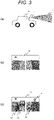
- FIG. 3 is a view illustrating an example of a case where a future temperature rise of the in-vehicle device 1 is predicted on the basis of an image captured by the in-vehicle device 1 which is a stereo camera
- FIG. 3(a) is a schematic view illustrating the vehicle 8
- FIG. 3(b) is a view illustrating one example of a captured image
- FIG. 3(c) is a view illustrating one example of a captured image and an example different from that of FIG. 3(b) .
- the in-vehicle device 1 is mounted on the vehicle 8.
- the in-vehicle device 1 obtains information of external environment as illustrated in an external environment captured image 9.
- a captured image 10 in FIG. 3(b) and a captured image 11 in FIG. 3(c) are examples of images obtained by the in-vehicle device 1.
- FIG. 4 is a table illustrating applications executed by the in-vehicle device 1.
- a left field indicates a case of the captured image 10
- a right field indicates a case of the captured image 11.
- the captured image 10 does not include the presences of a control target vehicle 12, the presence of an obstacle 13, and the presences of a pedestrian 14, a bicycle, and a motor bike in the surroundings. Therefore, the number of executed software applications is small in the in-vehicle device 1.
- the temperature change prediction unit 7 which has obtained the captured image 10 from the external environment information acquisition unit 2 detects that the number of executed software applications is small (only an application A is executed as illustrated in FIG. 4 ), comprehensively decides and predicts a temperature from a current temperature detected by the temperature detection unit 6, and outputs a prediction result to the control unit 4.
- the control unit 4 which has received the prediction result drives and stops the cooling unit 3 on the basis of the prediction result, and controls the cooling amount when driving the cooling unit 3. For example, the control unit 4 drives or stops the cooling unit 3 or decreases the cooling amount.
- the captured image 11 includes the presences of the control target vehicles 12, the obstacle 13 and the pedestrian 14 in the surroundings. Therefore, the number of executed software applications is large in the in-vehicle device 1.
- the temperature change prediction unit 7 which has obtained the captured image 11 from the external environment information acquisition unit 2 detects that the number of executed software applications is large (only applications A, B, C, D and E are executed as illustrated in FIG. 4 ), comprehensively decides and predicts a temperature from a current temperature detected by the temperature detection unit 6, and outputs a prediction result to the control unit 4.
- the control unit 4 which has received the prediction result drives and stops the cooling unit 3 on the basis of the prediction result, and controls the cooling amount when driving the cooling unit 3. For example, the control unit 4 starts driving the cooling unit 3 or increases the cooling amount.
- FIG. 5 is a flowchart illustrating one example of an operation of the in-vehicle device 1.
- the in-vehicle device 1 detects an object which is a control target from information obtained from the external environment information acquisition unit 2, and executes necessary software applications. Furthermore, the temperature change prediction unit 7 detects the number of software applications which are currently executed. In this case, when the number of executed software applications is two or more (step 501: YES), the processing load is high, and a high expectation of the temperature rise of the in-vehicle device 1 is eventually predicted (step 502).
- the temperature change prediction unit 7 acquires information of the current temperature from the temperature detection unit 6, and decides whether the acquired current temperature is a predetermined threshold or more or lower than the threshold (step 504).
- the threshold for the current temperature is a value determined from an operation guarantee temperature range of the in-vehicle device 1, and one or more thresholds can be set.
- the temperature change prediction unit 7 decides that cooling is necessary, drives the cooling unit 3, and sets the cooling amount to 100% to perform quick cooling (step 506).
- step 507 when the high expectation of the temperature rise of the in-vehicle device 1 is predicted, yet the current temperature from the temperature detection unit 6 is lower than the threshold (step 504: NO), although the cooling unit 3 is driven, the cooling amount is controlled within a range of 50 to 99% (step 507).
- the current temperature is not the threshold or more, and therefore is conventionally a condition that cooling is not started.
- cooling is started on the basis of external environment information, and a cooling start timing is made to come earlier.
- the cooling amount in step 507 may be controlled in another range such as a range of 1 to 49%.
- step 501: NO when the number of executed software applications is one or less (step 501: NO), and the expectation of the temperature rise of the in-vehicle device 1 is low yet the current temperature from the temperature detection unit 6 is the threshold or more (step 505: YES), although the cooling unit 3 is driven to lower the temperature of the in-vehicle device 1, the cooling amount is controlled in the range of 1 to 49% (step 508). In addition, the cooling amount in step 508 may be controlled in another range such as a range of 50 to 99%. In addition, when the temperature change prediction unit 7 does not predict temperature rises, the cooling amount of the cooling device may be decreased compared to a predetermined cooling amount.
- step 501: NO when the number of executed software applications is one or less (step 501: NO), and the expectation of the temperature rise of the in-vehicle device 1 is low yet the current temperature from the temperature detection unit 6 is lower than the threshold (step 505: NO), cooling is not necessary, and therefore the cooling unit 3 is stopped to reduce power consumption (step 509).
- the in-vehicle device 1 can predict future temperature rises from the number of executed software applications which depends on the external environment information, start cooling before the temperature rises, and realize miniaturization and lower cost of the cooling device, i.e., the cooling unit 3. Furthermore, even when cooling is necessary, it is possible to realize lower power consumption by appropriately controlling the cooling amount. Furthermore, when cooling is unnecessary, it is possible to make power consumption substantially zero by stopping driving the cooling device.
- the cooling amount controlled in steps 506, 507, 508, and 509 determines what percentage of a rated rotational speed (or a maximum rotational speed in some cases) a rotational speed of a fan is to perform driving in a case of a configuration where the cooling unit 3 rotates the fan and blows wind, and determines what percentage of a rated output (or a maximum output in some cases) an output is to drive this cooling unit 3 even in a case where the cooling unit 3 employs another configuration.
- FIG. 6 is a flowchart illustrating another example of the operation of the in-vehicle device 1.
- FIG. 7 is a table illustrating an example related to the invention of a processing load per application executed by the in-vehicle device 1. An association illustrated in the table in FIG. 7 is stored in advance in, for example, a storage device (not illustrated) in the temperature change prediction unit 7.
- Points from 1 to 10 points are allocated in advance to each software application implemented in the in-vehicle device 1 (i.e., executed by the in-vehicle device 1) according to the degree of a temperature rise due to each processing load per software application type (see FIG. 7 ).
- the in-vehicle device 1 acquires external environment information from the external environment information acquisition unit 2, and executes necessary software applications on the basis of the acquired information.
- the temperature change prediction unit 7 calculates a total of processing load points of each software application executed by using the association in FIG. 7 , and controls the cooling unit 3 according to the total point. For example, in the example in FIG.
- step 602 When the total of the processing load points of the software applications executed by the in-vehicle device 1 is 10 points or more (step 601: YES), a high expectation of the temperature rise of the in-vehicle device 1 is predicted (step 602).
- the temperature change prediction unit 7 acquires information of the current temperature from the temperature detection unit 6, and decides whether the acquired current temperature is a predetermined threshold or more or lower than the threshold (step 604).
- a decision result indicates that the current temperature is the threshold or more (step 604: YES)
- the temperature change prediction unit 7 decides that cooling is necessary, drives the cooling unit 3, and sets the cooling amount to 100% to perform quick cooling (step 606).
- step 607 when the high expectation of the temperature rise of the in-vehicle device 1 is predicted, yet the current temperature from the temperature detection unit 6 is lower than the threshold (step 604: NO), although the cooling unit 3 is driven, the cooling amount is controlled within a range of 50 to 99% (step 607).
- the current temperature is not the threshold or more, and therefore is conventionally a condition that cooling is not started.
- cooling is started on the basis of external environment information, and a cooling start timing is made to come earlier.
- the cooling amount in step 507 may be controlled in another range such as the range of 1 to 49%.
- step 601: NO when the processing load points of the executed software applications are less than 10 points (step 601: NO), and the expectation of the temperature rise of the in-vehicle device 1 is low yet the current temperature from the temperature detection unit 6 is the threshold or more (step 605: YES), although the cooling unit 3 is driven to lower the temperature of the in-vehicle device 1, the cooling amount is controlled in the range of 1 to 49% (step 608). In addition, the cooling amount in step 508 may be controlled in another range such as a range of 50 to 99%. In addition, when the temperature change prediction unit 7 does not predict temperature rises, the cooling amount of the cooling device may be decreased compared to the predetermined cooling amount.
- step 601: NO when the processing load points of the executed software applications are less than 10 points (step 601: NO), and the expectation of the temperature rise of the in-vehicle device 1 is low and the current temperature from the temperature detection unit 6 is lower than the threshold (step 605: NO), cooling is not necessary, and therefore the cooling unit 3 is stopped to reduce power consumption (step 609).
- the in-vehicle device 1 can predict future temperature rises from the processing load points of the executed software applications which depend on the external environment information, start cooling before the temperature rises, and realize miniaturization and lower cost of the cooling device, i.e., the cooling unit 3. Furthermore, even when cooling is necessary, it is possible to realize lower power consumption by appropriately controlling the cooling amount. Furthermore, when cooling is unnecessary, it is possible to make power consumption substantially zero by stopping driving the cooling device.
- FIG. 8 is a flowchart illustrating another example of the operation of the in-vehicle device 1.
- FIG. 9 is a table illustrating an example of a relationship between a brightness value and a brightness rank of brightness information obtained as external environment information from the external environment information acquisition unit 2. An association illustrated in the table in FIG. 9 is stored in advance in, for example, the storage device (not illustrated) in the temperature change prediction unit 7.
- the in-vehicle device 1 can predict a weather state of the external environment and control the cooling unit 3.
- the weather is good and there is sun light, it is expected that the brightness value also becomes high and an outdoor temperature is already high or rises in the future, and it is predicted that the temperature of the in-vehicle device 1 also rises.
- the weather is bad and there is no sun light or weak sun light, it is expected that the brightness value obtained from the external environment information acquisition unit 2 also becomes low and the outdoor temperature is relatively low or maintains a current state, and an expectation of the temperature rise of the in-vehicle device 1 is predicted to be low.
- FIG. 9 illustrates an example where the brightness value is ranked at four levels.
- a case where a brightness value is the highest is associated with a brightness rank 1
- cases where brightness values are lower are associated with brightness ranks 2, 3, and 4 in order.
- step 801 in FIG. 8 the same processing as that in step 501 in FIG. 5 is performed. Subsequently, in each of steps 802 to 809 in FIG. 8 , the same processing as that in each of steps 502 to 509 in FIG. 5 is performed. Subsequently, processing in step 810 is performed subsequently to step 807, processing in step 811 is performed subsequently to step 808, and processing in step 812 is performed subsequently to step 809.
- the brightness value is the highest, and the outdoor temperature is expected to rise.
- the cooling amount of the cooling unit 3 is increased by 30% at maximum.
- the cooling amount of the cooling unit 3 is increased by 20% at maximum.
- the cooling amount of the cooling unit 3 is increased by 10% at maximum.
- the brightness rank is 4, the brightness value is the lowest, an expectation of the outdoor temperature rise is low, and therefore the cooling amount of the cooling unit 3 maintains the current state.
- the temperature change prediction unit 7 does not predict temperature rises, the cooling amount of the cooling device may be decreased compared to a predetermined cooling amount.
- this control by predicting in advance a temperature rise of the in-vehicle device 1 depending on the weather and increasing the cooling amount of the cooling unit 3, it is possible to realize miniaturization and lower cost of the cooling device, i.e., the cooling unit 3 compared to control for starting cooling after the temperature rises. Furthermore, even when cooling is necessary, it is possible to realize lower power consumption by appropriately controlling the cooling amount. Furthermore, when cooling is unnecessary, it is possible to make power consumption substantially zero by stopping driving the cooling device.
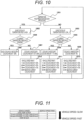
- FIG. 10 is a flowchart illustrating another example of the operation of the in-vehicle device 1.
- FIG. 11 is a table illustrating an example of a relationship between a vehicle speed and a vehicle speed rank obtained as external environment information from the external environment information acquisition unit 2.
- An association illustrated in the table in FIG. 9 is stored in advance in, for example, the storage device (not illustrated) in the temperature change prediction unit 7.
- the vehicle speed obtained from the external environment information acquisition unit 2 is used to predict a cooling state by a traveling wind, and control cooling. This takes into account that, when the in-vehicle device 1 is provided near a ceiling of the vehicle 8, the traveling wind cools the in-vehicle device 1.
- Speed information of the vehicle speed i.e., a current speed of the vehicle 8 may be acquired from a speedometer of the vehicle 8 which is the external environment information acquisition unit 2. Furthermore, the temperature change prediction unit 7 may occasionally acquire the image information of the image obtained from the external environment information acquisition unit 2 and obtained by capturing the outside of the vehicle 8, analyze this image information, and compute and acquire speed information of a vehicle speed, i.e., a current speed of the vehicle 8 on the basis of landscape changes accompanying a lapse of time.
- the in-vehicle device 1 imports to the temperature change prediction unit 7 the speed information of the vehicle speed, i.e., the current speed of the vehicle 8 obtained from the external environment information acquisition unit 2.
- the temperature change prediction unit 7 in the in-vehicle device 1 computes and obtains the vehicle speed by using the image information of the external environment obtained from the external environment information acquisition unit 2.
- the control unit 4 can control the cooling unit 3 according to the obtained current vehicle speed.
- the vehicle speed may be ranked according to each vehicle speed range.
- FIG. 11 illustrates an example where the vehicle speed is ranked at four levels. In the example in FIG. 11 , a case where the vehicle speed is the slowest is associated with a vehicle speed rank 1, and cases where vehicle speeds are faster are associated with vehicle speed ranks 2, 3, and 4 in order.
- step 1001 in FIG. 10 the same processing as that in step 501 in FIG. 5 is performed. Subsequently, in each of steps 1002 to 1009 in FIG. 10 , the same processing as that in each of steps 502 to 509 in FIG. 5 is performed. Subsequently, processing in step 1010 is performed subsequently to step 1007, processing in step 1011 is performed subsequently to step 1008, and processing in step 1012 is performed subsequently to step 1009.
- the cooling amount of the cooling unit 3 is increased by 30% at maximum.
- the cooling amount of the cooling unit 3 is increased by 20% at maximum.
- the cooling amount of the cooling unit 3 is increased by 10% at maximum.
- the vehicle speed rank is 4, the vehicle speed is the fastest, it can be expected that the traveling wind realizes sufficient cooling, and therefore the cooling amount of the cooling unit 3 maintains a current state.
- the cooling amount of the cooling device may be decreased compared to a predetermined cooling amount.
- this control by predicting in advance a temperature rise of the in-vehicle device 1 depending on the traveling wind and increasing the cooling amount of the cooling unit 3, it is possible to realize miniaturization and lower cost of the cooling device, i.e., the cooling unit 3 compared to control for starting cooling after the temperature rises. Furthermore, even when cooling is necessary, it is possible to realize lower power consumption by appropriately controlling the cooling amount. Furthermore, when cooling is unnecessary, it is possible to make power consumption substantially zero by stopping driving the cooling device.
- FIG. 12 is a flowchart illustrating another example of the operation of the in-vehicle device 1.
- FIG. 13 is a table illustrating an example of a relationship between an area group and an area type on the basis of current position information obtained as external environment information from the external environment information acquisition unit 2. An association illustrated in the table in FIG. 13 is stored in advance in, for example, the storage device (not illustrated) in the temperature change prediction unit 7.
- the in-vehicle device 1 uses position information of the current position obtained from the external environment information acquisition unit 2 to predict a future temperature rise of the in-vehicle device 1 on the basis of an high and low outdoor temperature tendency per area group (e.g., a cold area or a warm area) to which this current position belongs, and control cooling.
- an high and low outdoor temperature tendency per area group e.g., a cold area or a warm area
- the in-vehicle device 1 uses the position information obtained from the external environment information acquisition unit 2 to decide whether the temperature of an area of the current position is a location whose temperature tends to be high or a location whose temperature tends to be low on the basis of the association in FIG. 13 .
- a decision result is sent to the temperature change prediction unit 7, so that it is possible to control the cooling unit 3 according to whether the temperature of a current area is high or low.
- the area may be ranked at some levels on the basis of an annual average temperature or an annual highest temperature.
- FIG. 13 illustrates an example where an area group is ranked at four levels. In the example in FIG. 13 , a case where the annual average temperature is the highest is associated with an area type 1, and cases where the annual average temperatures are low are associated with area types 2, 3, and 4 in order.
- step 1201 in FIG. 12 the same processing as that in step 501 in FIG. 5 is performed. Subsequently, in each of steps 1202 to 1209 in FIG. 12 , the same processing as that in each of steps 502 to 509 in FIG. 5 is performed. Subsequently, processing in step 1210 is performed subsequently to step 1207, processing in step 1211 is performed subsequently to step 1208, and processing in step 1212 is performed subsequently to step 1209.
- step 1210, 1211, and 1212 when the area type is 1, the temperature tends to be high in this area, an expectation of a temperature rise of the in-vehicle device 1 is high, and therefore the cooling amount of the cooling unit 3 is increased by 30% at maximum. Similarly, when the area type is 2, the cooling amount of the cooling unit 3 is increased by 20%. When the area type is 3, the cooling amount of the cooling unit 3 is increased by 10%. When the area type is 4, the degree of an influence of the outdoor temperature on the temperature rise of the in-vehicle device 1 is low, the cooling amount of the cooling unit 3 is not increased, and the cooling amount maintains a current state. In addition, when the temperature change prediction unit 7 does not predict temperature rises, the cooling amount of the cooling device may be decreased compared to the predetermined cooling amount.
- this control by predicting in advance a temperature rise of the in-vehicle device 1 depending on the outdoor temperature and increasing the cooling amount of the cooling unit 3, it is possible to realize miniaturization and lower cost of the cooling device, i.e., the cooling unit 3 compared to control for starting cooling after the temperature rises. Furthermore, even when cooling is necessary, it is possible to realize lower power consumption by appropriately controlling the cooling amount. Furthermore, when cooling is unnecessary, it is possible to make power consumption substantially zero by stopping driving the cooling device.
Description
- The present invention relates to a control device for a cooling device and, more particularly, relates to a control device which controls the cooling device which cools an in-vehicle device mounted on a vehicle.
-
JP 2016-151374 A JP 2016-151374 A
Thedocument FR 2 780 349 A claim 1 which allows for projecting cooling control adjustments when position information on the entry of the vehicle into a cooler zone are received via a communication link. Further related art is disclosed inJP 2005 343386 A JP 2008 285126 A WO 2016/096612 A1 ,KR 2012 0076774 A FR 2 983 354 A1WO 2015/099463A1 . - However, control of the cooling device disclosed in
JP 2016-151374 A - In a case of a vehicle in particular, there are various types of traveling environment and the temperature changes due to the external factors are great. If the cooling device which cools an in-vehicle device to maintain capability of the in-vehicle device mounted on the vehicle cannot perform sufficient cooling due to the temperature changes due to the external factors or performs cooling with delay, it is concerned that the in-vehicle device cannot sufficiently exhibit the capability, and there is a problem from a viewpoint of energy saving if cooling requires high power.
- An object of the present invention is to provide a control device capable of controlling a cooling device in response to temperature changes due to external factors.
- To achieve the above object, the present invention proposes a control device as defined in
claim 1. Advantageous embodiments of the invention are indicated in the dependent claims 2-8. - The present invention can provide a control device capable of controlling a cooling device in response to temperature changes due to external factors.
- Problems, configurations, and effects other than the above problem, configuration, and effect will be made apparent from the following embodiment.
-
-
FIG. 1 is a block diagram illustrating configurations of an in-vehicle device and a cooling device which cools the in-vehicle device according to the first embodiment of the present invention. -
FIG. 2 is a graph illustrating one example of a temperature change of an in-vehicle device 1 illustrated inFIG. 1 . -
FIG. 3 is a view illustrating an example of a case where a future temperature rise of the in-vehicle device 1 is predicted on the basis of an image captured by the in-vehicle device 1 which is a stereo camera,FIG. 3(a) is a schematic view illustrating avehicle 8,FIG. 3(b) is a view illustrating one example of a captured image, andFIG. 3(c) is a view illustrating one example of a captured image and an example different from that ofFIG. 3(b) . -
FIG. 4 is a table illustrating applications executed by the in-vehicle device 1. -
FIG. 5 is a flowchart illustrating one example of an operation of the in-vehicle device 1. -
FIG. 6 is a flowchart illustrating another example of the operation of the in-vehicle device 1. -
FIG. 7 is a table illustrating an example related to the invention of a processing load per application executed by the in-vehicle device 1. -
FIG. 8 is a flowchart illustrating another example related to the invention of the operation of the in-vehicle device 1. -
FIG. 9 is a table illustrating an example related to the invention of a relationship between a brightness value and a brightness rank of brightness information obtained as external environment information from an external environmentinformation acquisition unit 2. -
FIG. 10 is a flowchart illustrating another example related to the invention of the operation of the in-vehicle device 1. -
FIG. 11 is a table illustrating an example related to the invention of a relationship between a vehicle speed and a vehicle speed rank obtained as external environment information from the external environmentinformation acquisition unit 2. -
FIG. 12 is a flowchart illustrating another example related to the invention of the operation of the in-vehicle device 1. -
FIG. 13 is a table illustrating an example related to the invention of a relationship between an area group and an area type on the basis of current position information obtained as external environment information from the external environmentinformation acquisition unit 2. - A configuration and an operation of a control device for a cooling device according to the first embodiment of the present invention will be described below with reference to the drawings.
-
FIG. 1 is a block diagram illustrating configurations of an in-vehicle device and a cooling device which cools this in-vehicle device according to the first embodiment of the present invention. - The in-
vehicle device 1 is a device which is mounted on avehicle 8 described later with reference toFIG. 3 , and is an object to be cooled by acooling unit 3 which is a cooling device. According to the present invention, the in-vehicle device 1 is the object to be cooled. However, a control device for the cooling device related to the present invention may control the cooling device which is not mounted on the vehicle and cools the object to be cooled. The in-vehicle device 1 may be any device such as various ECUs (Electronic Control Units), and, in addition, devices which are mounted on vehicles and need to be cooled. - The
cooling unit 3 which is the cooling device which cools the in-vehicle device 1 as the object to be cooled may be, for example, an air-cooled unit which blows air to the object to be cooled, a water-cooled unit which circulates a liquid, or a unit which cools a gas to be blown or a liquid to be circulated by using a known refrigerating cycle such as a vapor compression type or an absorption type. Furthermore, thecooling unit 3 may be an air conditioning device capable of cooling a vehicle interior of thevehicle 8 on which the in-vehicle device 1 is mounted. - An external environment
information acquisition unit 2 acquires external environment information which is information used to predict a future temperature rise of the in-vehicle device 1, and is information about the external environment of thevehicle 8. An external environmentinformation acquisition unit 2 acquires at least image information of an image obtained by capturing the outside of thevehicle 8, and optionally one further piece of information of, for example, position information of a current position of thevehicle 8, map information of a map of a current position of thevehicle 8, time information of a current time, period information of a current period (e.g., season) of a year, weather information of a current weather, brightness information of brightness at the outside of thevehicle 8, and speed information of a current speed of thevehicle 8 as the external environment information. - According to the invention, the external environment information acquired by the external environment
information acquisition unit 2 is image information of the image obtained by capturing the outside of thevehicle 8 and the external environmentinformation acquisition unit 2 is a camera including an imaging element. When further acquiring the position information of the current position of thevehicle 8 as the external environment information, the external environmentinformation acquisition unit 2 further includes a GPS reception device. When further acquiring the map information of the map of the current position of thevehicle 8 as the external environment information, the external environmentinformation acquisition unit 2 further includes the GPS reception device and a storage device which stores the map information of the current position. When further acquiring the time information of the current time as the external environment information, the external environmentinformation acquisition unit 2 further includes a clock device or a time acquisition device which acquires time information by performing communication via the Internet. When further acquiring the period information of the current period of the year as the external environment information, the external environmentinformation acquisition unit 2 further includes a period acquisition device which acquires the period information by performing communication via the Internet. When further acquiring the weather information of the current weather as the external environment information, the external environmentinformation acquisition unit 2 further includes a device which is a camera including the imaging element and acquires the weather information by extracting features of each weather from a captured image, or a weather acquisition device which acquires the weather information by performing communication via the Internet. When further acquiring the brightness information of the brightness at the outside of thevehicle 8 as the external environment information, the external environmentinformation acquisition unit 2 further includes a device which is the camera including the imaging element and acquires the brightness information from a captured image. When further acquiring speed information of a current speed of thevehicle 8 as the external environment information, the external environmentinformation acquisition unit 2 further includes a speedometer of thevehicle 8. - The external environment
information acquisition unit 2 outputs the acquired external environment information to the in-vehicle device 1. In the in-vehicle device 1 which has received an input of the external environment information from the external environmentinformation acquisition unit 2, a temperature change prediction unit 7 receives this inputted external environment information. - The in-
vehicle device 1 employs a configuration including atemperature detection unit 6 which detects a temperature of the in-vehicle device 1, a softwareapplication monitor unit 5 which monitors software applications executed by the in-vehicle device 1, a temperature change prediction unit 7 which predicts a future temperature rise of the in-vehicle device 1, and acontrol unit 4 which controls thecooling unit 3. The in-vehicle device 1 consumes power when the in-vehicle device 1 is powered on and operates, and a temperature rises as loss. Furthermore, the temperature of the in-vehicle device 1 rises due to an influence of external environment. The in-vehicle device 1 is provided in a dashboard (not illustrated) of thevehicle 8 in some cases, is provided near a battery (not illustrated) of thevehicle 8 in some cases and is provided near a gravity center position of thevehicle 8 in some cases. In addition, the external environmentinformation acquisition unit 2 may be provided in the in-vehicle device 1. - The
temperature detection unit 6 is, for example, a temperature sensor which uses a thermistor or a thermocouple, and detects the temperature of the in-vehicle device 1 and outputs a detection result of the temperature to the temperature change prediction unit 7. - The software
application monitor unit 5 monitors the number of applications which are currently executed by the in-vehicle device 1, and the degree of a processing load, and outputs a monitor result to the temperature change prediction unit 7. According to the invention, the softwareapplication monitor unit 5 calculates the degree of the processing load as types of applications which are being executed. - The temperature change prediction unit 7 predicts the future temperature rise of the in-
vehicle device 1 on the basis of a temperature detection result of thetemperature detection unit 6, a monitor result of the softwareapplication monitor unit 5, and the external environment information of the external environmentinformation acquisition unit 2. Furthermore, the temperature change prediction unit 7 predicts whether the temperature of the in-vehicle device 1 rises, maintains a current state, or drops in the future. A specific example of this prediction will be described later in detail. - Furthermore, the temperature change prediction unit 7 analyzes image information of an image obtained by capturing an outside of the
vehicle 8 among the external environment information of the external environmentinformation acquisition unit 2, and obtains information about presences of other vehicles, presences of obstacles, and presences of pedestrians, bicycles, and motorbikes in external environment. This information is also referred to as external environment information in some cases. According to the invention, the external environmentinformation acquisition unit 2 performs processing of analyzing the image information of the image obtained by capturing the outside of thevehicle 8, and obtaining the information about the presences of the other vehicles, the presences of the obstacles, and the presences of the pedestrians, the bicycles, and the motorbikes in the external environment. The external environmentinformation acquisition unit 2 outputs the information about the presences of the other vehicles, the presences of the obstacles, and the presences of the pedestrians, the bicycles, and the motorbikes as the external environment information to the in-vehicle device 1. - Furthermore, the temperature change prediction unit 7 may occasionally acquire the image information of the image obtained by capturing the outside of the
vehicle 8, analyze this image information, and compute and acquire speed information of a vehicle speed, i.e., a current speed of thevehicle 8 on the basis of landscape changes accompanying a lapse of time. - The
control unit 4 performs feed forward control on thecooling unit 3 on the basis of the external environment information obtained by the external environmentinformation acquisition unit 2 and the number and types of software applications which are being executed and are obtained by the softwareapplication monitor unit 5. A specific example of this control will be described below in detail. -
FIG. 2 is a graph illustrating one example of temperature changes of the in-vehicle device 1 illustrated inFIG. 1 . InFIG. 2 , a vertical axis indicates a temperature which rises, and a horizontal axis indicates a lapse of time. - Regarding the temperature rises of the in-
vehicle device 1, how the temperature changes from a current point of time and whether the temperature is expected to rise in the future or drop in the future have been conventionally unpredictable. According to the present embodiment, the temperature change prediction unit 7 predicts the future temperature rise of the in-vehicle device 1 on the basis of a temperature detection result of thetemperature detection unit 6, a monitor result of the softwareapplication monitor unit 5, and the external environment information of the external environmentinformation acquisition unit 2. In a case where the temperature of the in-vehicle device 1 is predicted to rise in the future as a result of this prediction, and even when a current detected temperature of thetemperature detection unit 6 is a temperature (which is less than a cooling start temperature) which does not need to be cooled by thecooling unit 3, thecontrol unit 4 causes thecooling unit 3 to start cooling in advance. When, for example, receiving a cooling start instruction from the temperature change prediction unit 7, thecontrol unit 4 drives thecooling unit 3. Furthermore, according to the instruction from the temperature change prediction unit 7, for example, thecontrol unit 4 performs control to drive and stop thecooling unit 3, and controls a cooling amount, too, when driving thecooling unit 3. - For example, there is a case where, when the temperature detection result of the
temperature detection unit 6 is higher than a predetermined threshold, the temperature change prediction unit 7 predicts that the temperature further rises in the future. There is a case where, when the temperature detection result of thetemperature detection unit 6 is within a predetermined threshold range, the temperature change prediction unit 7 predicts that the temperature does not change in the future. There is a case where, when the temperature detection result of thetemperature detection unit 6 is lower than the predetermined threshold, the temperature change prediction unit 7 predicts that the temperature further drops in the future. There is a case where, when a monitor result of the softwareapplication monitor unit 5 indicates that a predetermined number of applications or more are executed, the temperature change prediction unit 7 predicts that the temperature further rises in the future. There is a case where, when the monitor result of the softwareapplication monitor unit 5 indicates that a predetermined number of applications or more are not executed, the temperature change prediction unit 7 predicts that the temperature does not change in the future. There is a case where, when the monitor result of the softwareapplication monitor unit 5 indicates that a predetermined number of applications or more are not executed, the temperature change prediction unit 7 predicts that the temperature drops in the future. There is a case where, when the monitor result of the softwareapplication monitor unit 5 indicates that degrees of processing loads of the applications which are being executed are predetermined degrees or more, the temperature change prediction unit 7 predicts that the temperature further rises in the future. There is a case where, when the monitor result of the softwareapplication monitor unit 5 indicates that the degrees of processing loads of the applications which are being executed are not the predetermined degrees or more, the temperature change prediction unit 7 predicts that the temperature does not change in the future. There is a case where, when the monitor result of the softwareapplication monitor unit 5 indicates that the degrees of processing loads of the applications which are being executed are not the predetermined degrees or more, the temperature change prediction unit 7 predicts that the temperature drops in the future. According to the invention, the temperature change prediction unit 7 analyzes the image information of the image obtained by capturing the outside of thevehicle 8 on the basis of the external environment information of the external environmentinformation acquisition unit 2, and, when the number of the presences of the other vehicles, the presences of the obstacles, and the presences of the pedestrians, bicycles, and motorbikes in the external environment is a predetermined number or more, multiple applications are executed by the in-vehicle device 1 to analyze and deal with the presences, and the temperature change prediction unit 7 predicts that the temperature further rises in the future. Furthermore, for example, there is a case related to the invention where, when a current position on the basis of position information of the current position of thevehicle 8 is a high temperature area, the temperature change prediction unit 7 predicts that the temperature further rises on the basis of the external environment information of the external environmentinformation acquisition unit 2. There is a case related to the invention where, when the current position on the basis of map information of a map of the current position of thevehicle 8 is the high temperature area, the temperature change prediction unit 7 predicts that the temperature further rises in the future. There is a case related to the invention where, in a case of a predetermined time (e.g., a time past noon) on the basis of time information of the current time, the temperature change prediction unit 7 predicts that the temperature rises in the future. There is a case related to the invention where, in a case of a predetermined period (e.g., summer) on the basis of period information of a current period (e.g., season) in the year, the temperature change prediction unit 7 predicts that the temperature further rises in the future. There is a case related to the invention where, in a case of a predetermined weather (e.g., fine) on the basis of weather information of the current weather, the temperature change prediction unit 7 predicts that the temperature further rises in the future. There is a case related to the invention where, in a case of a predetermined brightness or more on the basis of brightness information of brightness at the outside of thevehicle 8, the weather is supposed to be good, and the temperature change prediction unit 7 predicts that the temperature further rises in the future. There is a case related to the invention where, in a case of a predetermined speed or less on the basis of speed information of the current speed of thevehicle 8, wind caused by traveling does not cool the vehicle body, and the temperature change prediction unit 7 predicts that the temperature further rises in the future. Furthermore, the temperature change prediction unit 7 may predict future temperature rises of the in-vehicle device 1 on the basis of a combination of each of the above conditions. - Thus, according to the present embodiment, by predicting the future temperature rises of the in-
vehicle device 1 and starting cooling in advance, it is not necessary to perform quick cooling compared to a case where the in-vehicle device 1 is cooled after the temperature rises, and it is possible to obtain a sufficient cooling effect even when a small cooling device is used as thecooling unit 3, and consequently realize lower cost. Furthermore, in a state where the in-vehicle device 1 does not need to be cooled, it is possible to suppress power consumption and realize low power consumption by stopping thecooling unit 3. Furthermore, it is possible to lower an average temperature in an operational life of the in-vehicle device 1 and realize long operational lives of the in-vehicle device 1 and thecooling unit 3. - As described above, although any device such as various ECUs (Electronic Control Units), and, in addition, devices which are mounted on vehicles and need to be cooled are applicable as the in-
vehicle device 1, a case where the in-vehicle device 1 is a stereo camera will be described below as an example. - In this example, the external environment
information acquisition unit 2 illustrated inFIG. 1 is a stereo camera imaging element, and this external environmentinformation acquisition unit 2 is provided in the in-vehicle device 1. -
FIG. 3 is a view illustrating an example of a case where a future temperature rise of the in-vehicle device 1 is predicted on the basis of an image captured by the in-vehicle device 1 which is a stereo camera,FIG. 3(a) is a schematic view illustrating thevehicle 8,FIG. 3(b) is a view illustrating one example of a captured image, andFIG. 3(c) is a view illustrating one example of a captured image and an example different from that ofFIG. 3(b) . - As illustrated in
FIG. 3(a) , the in-vehicle device 1 is mounted on thevehicle 8. The in-vehicle device 1 obtains information of external environment as illustrated in an external environment captured image 9. A capturedimage 10 inFIG. 3(b) and a capturedimage 11 inFIG. 3(c) are examples of images obtained by the in-vehicle device 1. -
FIG. 4 is a table illustrating applications executed by the in-vehicle device 1. InFIG. 4 , a left field indicates a case of the capturedimage 10, and a right field indicates a case of the capturedimage 11. - The captured
image 10 does not include the presences of acontrol target vehicle 12, the presence of anobstacle 13, and the presences of apedestrian 14, a bicycle, and a motor bike in the surroundings. Therefore, the number of executed software applications is small in the in-vehicle device 1. The temperature change prediction unit 7 which has obtained the capturedimage 10 from the external environmentinformation acquisition unit 2 detects that the number of executed software applications is small (only an application A is executed as illustrated inFIG. 4 ), comprehensively decides and predicts a temperature from a current temperature detected by thetemperature detection unit 6, and outputs a prediction result to thecontrol unit 4. Thecontrol unit 4 which has received the prediction result drives and stops thecooling unit 3 on the basis of the prediction result, and controls the cooling amount when driving thecooling unit 3. For example, thecontrol unit 4 drives or stops thecooling unit 3 or decreases the cooling amount. - On the other hand, the captured
image 11 includes the presences of thecontrol target vehicles 12, theobstacle 13 and thepedestrian 14 in the surroundings. Therefore, the number of executed software applications is large in the in-vehicle device 1. The temperature change prediction unit 7 which has obtained the capturedimage 11 from the external environmentinformation acquisition unit 2 detects that the number of executed software applications is large (only applications A, B, C, D and E are executed as illustrated inFIG. 4 ), comprehensively decides and predicts a temperature from a current temperature detected by thetemperature detection unit 6, and outputs a prediction result to thecontrol unit 4. Thecontrol unit 4 which has received the prediction result drives and stops thecooling unit 3 on the basis of the prediction result, and controls the cooling amount when driving thecooling unit 3. For example, thecontrol unit 4 starts driving thecooling unit 3 or increases the cooling amount. - Next, an example of future temperature rise prediction on the basis of the number of software applications which are being executed, and cooling control will be described with reference to
FIG. 5 . -
FIG. 5 is a flowchart illustrating one example of an operation of the in-vehicle device 1. - The in-
vehicle device 1 detects an object which is a control target from information obtained from the external environmentinformation acquisition unit 2, and executes necessary software applications. Furthermore, the temperature change prediction unit 7 detects the number of software applications which are currently executed. In this case, when the number of executed software applications is two or more (step 501: YES), the processing load is high, and a high expectation of the temperature rise of the in-vehicle device 1 is eventually predicted (step 502). - Next, the temperature change prediction unit 7 acquires information of the current temperature from the
temperature detection unit 6, and decides whether the acquired current temperature is a predetermined threshold or more or lower than the threshold (step 504). The threshold for the current temperature is a value determined from an operation guarantee temperature range of the in-vehicle device 1, and one or more thresholds can be set. When a decision result indicates that the current temperature is the threshold or more (step 504: YES), the temperature change prediction unit 7 decides that cooling is necessary, drives thecooling unit 3, and sets the cooling amount to 100% to perform quick cooling (step 506). - Next, when the high expectation of the temperature rise of the in-
vehicle device 1 is predicted, yet the current temperature from thetemperature detection unit 6 is lower than the threshold (step 504: NO), although thecooling unit 3 is driven, the cooling amount is controlled within a range of 50 to 99% (step 507). In thisstep 507, the current temperature is not the threshold or more, and therefore is conventionally a condition that cooling is not started. However, according to the present embodiment, cooling is started on the basis of external environment information, and a cooling start timing is made to come earlier. In addition, the cooling amount instep 507 may be controlled in another range such as a range of 1 to 49%. - Furthermore, when the number of executed software applications is one or less (step 501: NO), and the expectation of the temperature rise of the in-
vehicle device 1 is low yet the current temperature from thetemperature detection unit 6 is the threshold or more (step 505: YES), although thecooling unit 3 is driven to lower the temperature of the in-vehicle device 1, the cooling amount is controlled in the range of 1 to 49% (step 508). In addition, the cooling amount instep 508 may be controlled in another range such as a range of 50 to 99%. In addition, when the temperature change prediction unit 7 does not predict temperature rises, the cooling amount of the cooling device may be decreased compared to a predetermined cooling amount. - Lastly, when the number of executed software applications is one or less (step 501: NO), and the expectation of the temperature rise of the in-
vehicle device 1 is low yet the current temperature from thetemperature detection unit 6 is lower than the threshold (step 505: NO), cooling is not necessary, and therefore thecooling unit 3 is stopped to reduce power consumption (step 509). - By performing the above control, the in-
vehicle device 1 can predict future temperature rises from the number of executed software applications which depends on the external environment information, start cooling before the temperature rises, and realize miniaturization and lower cost of the cooling device, i.e., thecooling unit 3. Furthermore, even when cooling is necessary, it is possible to realize lower power consumption by appropriately controlling the cooling amount. Furthermore, when cooling is unnecessary, it is possible to make power consumption substantially zero by stopping driving the cooling device. - In addition, the cooling amount controlled in
steps cooling unit 3 rotates the fan and blows wind, and determines what percentage of a rated output (or a maximum output in some cases) an output is to drive thiscooling unit 3 even in a case where thecooling unit 3 employs another configuration. - Next, an example related to the invention of future temperature rise prediction on the basis of processing loads of software applications, and cooling control will be described with reference to
FIGS. 6 and 7 . -
FIG. 6 is a flowchart illustrating another example of the operation of the in-vehicle device 1. -
FIG. 7 is a table illustrating an example related to the invention of a processing load per application executed by the in-vehicle device 1. An association illustrated in the table inFIG. 7 is stored in advance in, for example, a storage device (not illustrated) in the temperature change prediction unit 7. - Points from 1 to 10 points are allocated in advance to each software application implemented in the in-vehicle device 1 (i.e., executed by the in-vehicle device 1) according to the degree of a temperature rise due to each processing load per software application type (see
FIG. 7 ). The in-vehicle device 1 acquires external environment information from the external environmentinformation acquisition unit 2, and executes necessary software applications on the basis of the acquired information. In this case, the temperature change prediction unit 7 calculates a total of processing load points of each software application executed by using the association inFIG. 7 , and controls thecooling unit 3 according to the total point. For example, in the example inFIG. 7 ,10 points are allocated to the software application A, eight points are allocated to the software application B, five points are allocated to the software application C, three points are allocated to the software application D, and two points are allocated to the software application E. When, for example, only the software applications D and E are executed, the processing load point is five points in total. - When the total of the processing load points of the software applications executed by the in-
vehicle device 1 is 10 points or more (step 601: YES), a high expectation of the temperature rise of the in-vehicle device 1 is predicted (step 602). - Next, the temperature change prediction unit 7 acquires information of the current temperature from the
temperature detection unit 6, and decides whether the acquired current temperature is a predetermined threshold or more or lower than the threshold (step 604). When a decision result indicates that the current temperature is the threshold or more (step 604: YES), the temperature change prediction unit 7 decides that cooling is necessary, drives thecooling unit 3, and sets the cooling amount to 100% to perform quick cooling (step 606). - Next, when the high expectation of the temperature rise of the in-
vehicle device 1 is predicted, yet the current temperature from thetemperature detection unit 6 is lower than the threshold (step 604: NO), although thecooling unit 3 is driven, the cooling amount is controlled within a range of 50 to 99% (step 607). In thisstep 507, the current temperature is not the threshold or more, and therefore is conventionally a condition that cooling is not started. However, according to the present embodiment, cooling is started on the basis of external environment information, and a cooling start timing is made to come earlier. In addition, the cooling amount instep 507 may be controlled in another range such as the range of 1 to 49%. - Furthermore, when the processing load points of the executed software applications are less than 10 points (step 601: NO), and the expectation of the temperature rise of the in-
vehicle device 1 is low yet the current temperature from thetemperature detection unit 6 is the threshold or more (step 605: YES), although thecooling unit 3 is driven to lower the temperature of the in-vehicle device 1, the cooling amount is controlled in the range of 1 to 49% (step 608). In addition, the cooling amount instep 508 may be controlled in another range such as a range of 50 to 99%. In addition, when the temperature change prediction unit 7 does not predict temperature rises, the cooling amount of the cooling device may be decreased compared to the predetermined cooling amount. - Lastly, when the processing load points of the executed software applications are less than 10 points (step 601: NO), and the expectation of the temperature rise of the in-
vehicle device 1 is low and the current temperature from thetemperature detection unit 6 is lower than the threshold (step 605: NO), cooling is not necessary, and therefore thecooling unit 3 is stopped to reduce power consumption (step 609). - By performing the above control, the in-
vehicle device 1 can predict future temperature rises from the processing load points of the executed software applications which depend on the external environment information, start cooling before the temperature rises, and realize miniaturization and lower cost of the cooling device, i.e., thecooling unit 3. Furthermore, even when cooling is necessary, it is possible to realize lower power consumption by appropriately controlling the cooling amount. Furthermore, when cooling is unnecessary, it is possible to make power consumption substantially zero by stopping driving the cooling device. - Next, an example of future temperature rise prediction on the basis of brightness information, and cooling control will be described with reference to
FIGS. 8 and 9 . -
FIG. 8 is a flowchart illustrating another example of the operation of the in-vehicle device 1. -
FIG. 9 is a table illustrating an example of a relationship between a brightness value and a brightness rank of brightness information obtained as external environment information from the external environmentinformation acquisition unit 2. An association illustrated in the table inFIG. 9 is stored in advance in, for example, the storage device (not illustrated) in the temperature change prediction unit 7. - By importing to the temperature change prediction unit 7 the brightness information of the external environment obtained from the external environment
information acquisition unit 2, the in-vehicle device 1 can predict a weather state of the external environment and control thecooling unit 3. When the weather is good and there is sun light, it is expected that the brightness value also becomes high and an outdoor temperature is already high or rises in the future, and it is predicted that the temperature of the in-vehicle device 1 also rises. On the other hand, when the weather is bad and there is no sun light or weak sun light, it is expected that the brightness value obtained from the external environmentinformation acquisition unit 2 also becomes low and the outdoor temperature is relatively low or maintains a current state, and an expectation of the temperature rise of the in-vehicle device 1 is predicted to be low. - Data on a relation between the brightness value obtained from the external environment
information acquisition unit 2, and the weather state and a temperature rise and drop may be acquired in advance by an experiment, and ranked at several levels.FIG. 9 illustrates an example where the brightness value is ranked at four levels. In the example inFIG. 9 , a case where a brightness value is the highest is associated with abrightness rank 1, and cases where brightness values are lower are associated withbrightness ranks - In
step 801 inFIG. 8 , the same processing as that instep 501 inFIG. 5 is performed. Subsequently, in each ofsteps 802 to 809 inFIG. 8 , the same processing as that in each ofsteps 502 to 509 inFIG. 5 is performed. Subsequently, processing instep 810 is performed subsequently to step 807, processing instep 811 is performed subsequently to step 808, and processing instep 812 is performed subsequently to step 809. - When the brightness rank is 1 in each of
steps cooling unit 3 is increased by 30% at maximum. Similarly, when the brightness rank is 2, the cooling amount of thecooling unit 3 is increased by 20% at maximum. When the brightness rank is 1, the cooling amount of thecooling unit 3 is increased by 10% at maximum. When the brightness rank is 4, the brightness value is the lowest, an expectation of the outdoor temperature rise is low, and therefore the cooling amount of thecooling unit 3 maintains the current state. In addition, when the temperature change prediction unit 7 does not predict temperature rises, the cooling amount of the cooling device may be decreased compared to a predetermined cooling amount. - According to this control, by predicting in advance a temperature rise of the in-
vehicle device 1 depending on the weather and increasing the cooling amount of thecooling unit 3, it is possible to realize miniaturization and lower cost of the cooling device, i.e., thecooling unit 3 compared to control for starting cooling after the temperature rises. Furthermore, even when cooling is necessary, it is possible to realize lower power consumption by appropriately controlling the cooling amount. Furthermore, when cooling is unnecessary, it is possible to make power consumption substantially zero by stopping driving the cooling device. - Next, an example of future temperature rise prediction on the basis of a vehicle speed, and cooling control will be described with reference to
FIGS. 10 and 11 . -
FIG. 10 is a flowchart illustrating another example of the operation of the in-vehicle device 1. -
FIG. 11 is a table illustrating an example of a relationship between a vehicle speed and a vehicle speed rank obtained as external environment information from the external environmentinformation acquisition unit 2. An association illustrated in the table inFIG. 9 is stored in advance in, for example, the storage device (not illustrated) in the temperature change prediction unit 7. - In this example, the vehicle speed obtained from the external environment
information acquisition unit 2 is used to predict a cooling state by a traveling wind, and control cooling. This takes into account that, when the in-vehicle device 1 is provided near a ceiling of thevehicle 8, the traveling wind cools the in-vehicle device 1. - Speed information of the vehicle speed, i.e., a current speed of the
vehicle 8 may be acquired from a speedometer of thevehicle 8 which is the external environmentinformation acquisition unit 2. Furthermore, the temperature change prediction unit 7 may occasionally acquire the image information of the image obtained from the external environmentinformation acquisition unit 2 and obtained by capturing the outside of thevehicle 8, analyze this image information, and compute and acquire speed information of a vehicle speed, i.e., a current speed of thevehicle 8 on the basis of landscape changes accompanying a lapse of time. - The in-
vehicle device 1 imports to the temperature change prediction unit 7 the speed information of the vehicle speed, i.e., the current speed of thevehicle 8 obtained from the external environmentinformation acquisition unit 2. Alternatively, the temperature change prediction unit 7 in the in-vehicle device 1 computes and obtains the vehicle speed by using the image information of the external environment obtained from the external environmentinformation acquisition unit 2. Thecontrol unit 4 can control thecooling unit 3 according to the obtained current vehicle speed. When the vehicle speed is fast, the traveling wind cools the vehicle body, and the temperature of the in-vehicle device 1 also lowers. By contrast with this, when the vehicle speed is slow, it cannot be expected that the traveling wind cools the vehicle body, and the temperature of the in-vehicle device 1 rises. The vehicle speed may be ranked according to each vehicle speed range.FIG. 11 illustrates an example where the vehicle speed is ranked at four levels. In the example inFIG. 11 , a case where the vehicle speed is the slowest is associated with avehicle speed rank 1, and cases where vehicle speeds are faster are associated with vehicle speed ranks 2, 3, and 4 in order. - In
step 1001 inFIG. 10 , the same processing as that instep 501 inFIG. 5 is performed. Subsequently, in each ofsteps 1002 to 1009 inFIG. 10 , the same processing as that in each ofsteps 502 to 509 inFIG. 5 is performed. Subsequently, processing instep 1010 is performed subsequently to step 1007, processing instep 1011 is performed subsequently to step 1008, and processing instep 1012 is performed subsequently to step 1009. - In each of
steps cooling unit 3 is increased by 30% at maximum. Similarly, when the vehicle speed rank is 2, the cooling amount of thecooling unit 3 is increased by 20% at maximum. When the vehicle speed rank is 3, the cooling amount of thecooling unit 3 is increased by 10% at maximum. When the vehicle speed rank is 4, the vehicle speed is the fastest, it can be expected that the traveling wind realizes sufficient cooling, and therefore the cooling amount of thecooling unit 3 maintains a current state. In addition, when the temperature change prediction unit 7 does not predict temperature rises, the cooling amount of the cooling device may be decreased compared to a predetermined cooling amount. - According to this control, by predicting in advance a temperature rise of the in-
vehicle device 1 depending on the traveling wind and increasing the cooling amount of thecooling unit 3, it is possible to realize miniaturization and lower cost of the cooling device, i.e., thecooling unit 3 compared to control for starting cooling after the temperature rises. Furthermore, even when cooling is necessary, it is possible to realize lower power consumption by appropriately controlling the cooling amount. Furthermore, when cooling is unnecessary, it is possible to make power consumption substantially zero by stopping driving the cooling device. - Next, an example of future temperature rise prediction on the basis of position information of a current position, and cooling control will be described with reference to
FIGS. 12 and 13 . -
FIG. 12 is a flowchart illustrating another example of the operation of the in-vehicle device 1. -
FIG. 13 is a table illustrating an example of a relationship between an area group and an area type on the basis of current position information obtained as external environment information from the external environmentinformation acquisition unit 2. An association illustrated in the table inFIG. 13 is stored in advance in, for example, the storage device (not illustrated) in the temperature change prediction unit 7. - In this example, the in-
vehicle device 1 uses position information of the current position obtained from the external environmentinformation acquisition unit 2 to predict a future temperature rise of the in-vehicle device 1 on the basis of an high and low outdoor temperature tendency per area group (e.g., a cold area or a warm area) to which this current position belongs, and control cooling. - The in-
vehicle device 1 uses the position information obtained from the external environmentinformation acquisition unit 2 to decide whether the temperature of an area of the current position is a location whose temperature tends to be high or a location whose temperature tends to be low on the basis of the association inFIG. 13 . A decision result is sent to the temperature change prediction unit 7, so that it is possible to control thecooling unit 3 according to whether the temperature of a current area is high or low. The area may be ranked at some levels on the basis of an annual average temperature or an annual highest temperature.FIG. 13 illustrates an example where an area group is ranked at four levels. In the example inFIG. 13 , a case where the annual average temperature is the highest is associated with anarea type 1, and cases where the annual average temperatures are low are associated witharea types - In
step 1201 inFIG. 12 , the same processing as that instep 501 inFIG. 5 is performed. Subsequently, in each ofsteps 1202 to 1209 inFIG. 12 , the same processing as that in each ofsteps 502 to 509 inFIG. 5 is performed. Subsequently, processing instep 1210 is performed subsequently to step 1207, processing instep 1211 is performed subsequently to step 1208, and processing instep 1212 is performed subsequently to step 1209. - In each of
steps vehicle device 1 is high, and therefore the cooling amount of thecooling unit 3 is increased by 30% at maximum. Similarly, when the area type is 2, the cooling amount of thecooling unit 3 is increased by 20%. When the area type is 3, the cooling amount of thecooling unit 3 is increased by 10%. When the area type is 4, the degree of an influence of the outdoor temperature on the temperature rise of the in-vehicle device 1 is low, the cooling amount of thecooling unit 3 is not increased, and the cooling amount maintains a current state. In addition, when the temperature change prediction unit 7 does not predict temperature rises, the cooling amount of the cooling device may be decreased compared to the predetermined cooling amount. - According to this control, by predicting in advance a temperature rise of the in-
vehicle device 1 depending on the outdoor temperature and increasing the cooling amount of thecooling unit 3, it is possible to realize miniaturization and lower cost of the cooling device, i.e., thecooling unit 3 compared to control for starting cooling after the temperature rises. Furthermore, even when cooling is necessary, it is possible to realize lower power consumption by appropriately controlling the cooling amount. Furthermore, when cooling is unnecessary, it is possible to make power consumption substantially zero by stopping driving the cooling device. - For decision conditions in
steps application monitor unit 5 are used . -
- 1 : in-vehicle device (object to be cooled)
- 2 : external environment information acquisition unit
- 3 : cooling unit
- 4 : control unit
- 5 : software application monitor unit
- 6 : temperature detection unit
- 7 : temperature change prediction unit
- 8 : vehicle
- 9 : external environment captured image
- 10 : captured image
- 11 : captured image
- 12 : control target vehicle
- 13 : obstacle
- 14 : pedestrian
Claims (8)
- A control device for a cooling device (3) comprising:an external environment information acquisition unit (2) for acquiring external environment information, which is information about an outside of a vehicle (8) on which an in-vehicle device (1) as the object to be cooled is mounted and concerns temperature changes of the in-vehicle device;a temperature change prediction unit (7) for predicting the temperature changes of the object to be cooled; anda control unit (4) for controlling the cooling device (3) for cooling the object to be cooled, such control carried out on the basis of the prediction results according to the temperature change prediction unit (7);wherein the external environment information is information on the presence of other vehicles, obstacles, pedestrians, bicycles and motorbikes in the external environment of the vehicle, which is obtained from image information of an image obtained by capturing the outside of the vehicle (8);characterized in thatthe temperature change prediction unit (7) is adapted to calculate a processing load of the in-vehicle device (1) due to the execution of software applications in the in-vehicle device (1) on the basis of the external environment information acquired from the external environment information acquisition unit (2), and to predict the temperature changes of the in-vehicle device (1) on the basis of the calculated processing load.
- The control device for the cooling device according to claim 1, wherein the control unit (4) is adapted to control a cooling amount or a cooling timing of the cooling device (3).
- The control device for the cooling device according to claim 1, wherein, when the temperature change prediction unit (7) predicts that the temperature rises, the control unit (4) is adapted to increase a cooling amount of the cooling device (3) compared to a predetermined cooling amount.
- The control device for the cooling device according to claim 1, wherein, when the temperature change prediction unit (7) does not predict that the temperature rises, the control unit (4) is adapted to decrease a cooling amount of the cooling device (3) compared to a predetermined cooling amount.
- The control device for the cooling device according to claim 1, wherein, when the temperature change prediction unit (7) predicts that the temperature rises, the control unit (4) is adapted to make a cooling timing of the cooling device (3) come earlier than a predetermined cooling timing.
- The control device for the cooling device according to claim 1, wherein the external environment information further includes at least one of map information of a map of a current position of the vehicle (8), time information of a current time, period information of a current period of a year, weather information of a current weather, brightness information of brightness at the outside of the vehicle, position information of a current position of the vehicle (8), and speed information of a current speed of the vehicle (8).
- The control device for the cooling device according to claim 1, further comprising a temperature detection unit (6) for detecting a temperature of the object to be cooled,
wherein the temperature change prediction unit (7) is adapted to predict the temperature changes of the object to be cooled on the calculated processing load, and a detection result of the temperature detection unit (6). - The control device for the cooling device according to claim 1, wherein
the cooling device (3) is a cooling device mounted on the in-vehicle device (1) or an air conditioning device capable of cooling a vehicle interior of the vehicle (8) on which the in-vehicle device (1) is mounted.
Applications Claiming Priority (2)
| Application Number | Priority Date | Filing Date | Title |
|---|---|---|---|
| JP2016245151 | 2016-12-19 | ||
| PCT/JP2017/043934 WO2018116840A1 (en) | 2016-12-19 | 2017-12-07 | Control device for cooling device |
Publications (3)
| Publication Number | Publication Date |
|---|---|
| EP3556588A1 EP3556588A1 (en) | 2019-10-23 |
| EP3556588A4 EP3556588A4 (en) | 2020-09-30 |
| EP3556588B1 true EP3556588B1 (en) | 2023-03-08 |
Family
ID=62626101
Family Applications (1)
| Application Number | Title | Priority Date | Filing Date |
|---|---|---|---|
| EP17883424.8A Active EP3556588B1 (en) | 2016-12-19 | 2017-12-07 | Control device for cooling device |
Country Status (4)
| Country | Link |
|---|---|
| US (1) | US11065938B2 (en) |
| EP (1) | EP3556588B1 (en) |
| JP (1) | JP6734935B2 (en) |
| WO (1) | WO2018116840A1 (en) |
Families Citing this family (5)
| Publication number | Priority date | Publication date | Assignee | Title |
|---|---|---|---|---|
| JP2020141215A (en) * | 2019-02-27 | 2020-09-03 | シャープ株式会社 | Electronic apparatus, terminal, processing method, temperature rise suppression system, control program and storage medium |
| RU2746427C1 (en) * | 2019-12-18 | 2021-04-13 | Федеральное государственное автономное образовательное учреждение высшего образования "Московский политехнический университет" (Московский Политех) | Thermal control method for battery energy storage |
| CN111976519A (en) * | 2020-07-04 | 2020-11-24 | 江苏华鹏智能仪表科技股份有限公司 | Automatic heat dissipation system and method for charging pile module |
| CN113147453B (en) * | 2021-02-27 | 2023-12-22 | 武汉北方电力有限公司 | Air-cooled and water-cooled integrated dustproof charging pile |
| WO2024090389A1 (en) * | 2022-10-24 | 2024-05-02 | ソフトバンクグループ株式会社 | Cooling execution device, cooling execution method, cooling execution program, and vehicle |
Citations (1)
| Publication number | Priority date | Publication date | Assignee | Title |
|---|---|---|---|---|
| WO2015099463A1 (en) * | 2013-12-24 | 2015-07-02 | 엘지전자 주식회사 | Vehicle driving assist device and vehicle having same |
Family Cites Families (18)
| Publication number | Priority date | Publication date | Assignee | Title |
|---|---|---|---|---|
| FR2780349B1 (en) | 1998-06-30 | 2000-09-08 | Valeo Climatisation | CONTROLLED CONTROL DEVICE FOR A VENTILATION, HEATING AND AIR CONDITIONING INSTALLATION OF A MOTOR VEHICLE INTERIOR |
| JP4393277B2 (en) * | 2004-06-04 | 2010-01-06 | 富士通テン株式会社 | Car room temperature monitoring device |
| US8972161B1 (en) * | 2005-11-17 | 2015-03-03 | Invent.Ly, Llc | Power management systems and devices |
| JP2007148572A (en) | 2005-11-24 | 2007-06-14 | Toshiba Corp | Electronic apparatus, temperature control device and temperature control method |
| US7962441B2 (en) * | 2006-09-22 | 2011-06-14 | Denso Corporation | Air conditioner for vehicle and controlling method thereof |
| US20080179040A1 (en) * | 2007-01-26 | 2008-07-31 | Rosenbaum Richard W | Method to heat or cool vehicle battery and passenger compartments |
| JP5087993B2 (en) | 2007-05-21 | 2012-12-05 | トヨタ自動車株式会社 | Air conditioning controller |
| JP2011117683A (en) * | 2009-12-04 | 2011-06-16 | Sharp Corp | Air conditioner and control method thereof |
| KR20120076774A (en) | 2010-12-30 | 2012-07-10 | 서울메트로 | System and method for controlling cooling and heating level of train |
| US20130079978A1 (en) * | 2011-09-22 | 2013-03-28 | Honda Motor Co., Ltd. | Preconditioning a vehicle |
| DE102011086569A1 (en) * | 2011-11-17 | 2013-05-23 | Sb Limotive Company Ltd. | Method for controlling the temperature of a vehicle with at least partial electric drive, vehicle and charging station |
| FR2983354B1 (en) | 2011-11-24 | 2015-12-18 | Renault Sas | METHOD FOR REGULATING THE TEMPERATURE OF A TRACTION BATTERY OF A CHARGED ELECTRIC VEHICLE, PARTICULARLY DURING RAPID CHARGING OF THE BATTERY |
| JP2014061798A (en) * | 2012-09-21 | 2014-04-10 | Denso Corp | Vehicular heat management system |
| GB201408912D0 (en) * | 2014-05-20 | 2014-07-02 | Jaguar Land Rover Ltd | Vehicle control system and method |
| JP2016107910A (en) * | 2014-12-09 | 2016-06-20 | 株式会社デンソー | Vehicle power supply system |
| DE102014226514A1 (en) | 2014-12-19 | 2016-06-23 | Bayerische Motoren Werke Aktiengesellschaft | Method and air conditioning system for the air conditioning of an electric or hybrid vehicle |
| JP6423736B2 (en) | 2015-02-17 | 2018-11-14 | オーム電機株式会社 | Cooling system |
| DE102016210130A1 (en) * | 2016-06-08 | 2017-12-14 | Continental Automotive Gmbh | Method for controlling air conditioning components of a motor vehicle |
-
2017
- 2017-12-07 WO PCT/JP2017/043934 patent/WO2018116840A1/en active Application Filing
- 2017-12-07 US US16/461,669 patent/US11065938B2/en active Active
- 2017-12-07 JP JP2018557661A patent/JP6734935B2/en active Active
- 2017-12-07 EP EP17883424.8A patent/EP3556588B1/en active Active
Patent Citations (1)
| Publication number | Priority date | Publication date | Assignee | Title |
|---|---|---|---|---|
| WO2015099463A1 (en) * | 2013-12-24 | 2015-07-02 | 엘지전자 주식회사 | Vehicle driving assist device and vehicle having same |
Also Published As
| Publication number | Publication date |
|---|---|
| JPWO2018116840A1 (en) | 2019-10-24 |
| EP3556588A1 (en) | 2019-10-23 |
| EP3556588A4 (en) | 2020-09-30 |
| JP6734935B2 (en) | 2020-08-05 |
| US11065938B2 (en) | 2021-07-20 |
| US20190351780A1 (en) | 2019-11-21 |
| WO2018116840A1 (en) | 2018-06-28 |
Similar Documents
| Publication | Publication Date | Title |
|---|---|---|
| EP3556588B1 (en) | Control device for cooling device | |
| EP3869930B1 (en) | Thermal reduction system for an autonomous vehicle | |
| CN107882625B (en) | Control method and device for electronic fan of engine | |
| US20200171954A1 (en) | Method of Cooling Control for Drive Motor of Electric Vehicle | |
| US20230294508A1 (en) | Thermal management control method and apparatus, and vehicle | |
| CN111969280A (en) | Temperature control method and device and electronic equipment | |
| KR101755480B1 (en) | Cooling fan control method for vehicle | |
| CN114111198A (en) | Refrigerator control method and refrigerator | |
| CN107830685B (en) | Multi-system refrigerator fan energy-saving control method, controller, readable medium and refrigerator | |
| US20140174712A1 (en) | Cooling control method and system for battery | |
| US20240123797A1 (en) | Vehicle refrigeration control method, apparatus, device, medium and program product | |
| WO2020176027A1 (en) | A method of controlling a cooling system of a vehicle, and a vehicle | |
| CN112959996A (en) | Vehicle control method and device and vehicle | |
| CN112208298B (en) | Vehicle cold air control system and method, vehicle and storage medium | |
| CN109163489B (en) | Refrigeration method and device and horizontal air-cooled refrigeration cabinet with device | |
| CN110749120B (en) | Method and device for controlling operation of semiconductor refrigeration equipment and refrigeration equipment | |
| KR101633934B1 (en) | Method for calculating torque of compressor | |
| KR102391004B1 (en) | Method and system for controlling water pump | |
| CN116552332A (en) | Heat dissipation control method for battery of electric automobile, electronic equipment and storage medium | |
| JP2010179695A (en) | Vehicle air-conditioning control device | |
| CN117341429A (en) | Battery water pump control method and device for vehicle | |
| CN116619978A (en) | Vehicle air conditioner fan control method, device, equipment and readable storage medium | |
| CN110749120A (en) | Method and device for controlling operation of semiconductor refrigeration equipment and refrigeration equipment | |
| CN117183720A (en) | Control method and device for vehicle thermal management system, electronic equipment and storage medium | |
| CN117869273A (en) | Multi-parameter response-based electric water pump control method and system |
Legal Events
| Date | Code | Title | Description |
|---|---|---|---|
| STAA | Information on the status of an ep patent application or granted ep patent |
Free format text: STATUS: THE INTERNATIONAL PUBLICATION HAS BEEN MADE |
|
| PUAI | Public reference made under article 153(3) epc to a published international application that has entered the european phase |
Free format text: ORIGINAL CODE: 0009012 |
|
| STAA | Information on the status of an ep patent application or granted ep patent |
Free format text: STATUS: REQUEST FOR EXAMINATION WAS MADE |
|
| 17P | Request for examination filed |
Effective date: 20190506 |
|
| AK | Designated contracting states |
Kind code of ref document: A1 Designated state(s): AL AT BE BG CH CY CZ DE DK EE ES FI FR GB GR HR HU IE IS IT LI LT LU LV MC MK MT NL NO PL PT RO RS SE SI SK SM TR |
|
| AX | Request for extension of the european patent |
Extension state: BA ME |
|
| DAV | Request for validation of the european patent (deleted) | ||
| DAX | Request for extension of the european patent (deleted) | ||
| A4 | Supplementary search report drawn up and despatched |
Effective date: 20200902 |
|
| RIC1 | Information provided on ipc code assigned before grant |
Ipc: B60H 1/14 20060101ALI20200827BHEP Ipc: F24F 11/88 20180101ALI20200827BHEP Ipc: B60H 1/00 20060101ALI20200827BHEP Ipc: F24F 11/89 20180101ALI20200827BHEP Ipc: F24F 110/00 20180101ALI20200827BHEP Ipc: B60H 1/22 20060101ALI20200827BHEP Ipc: B60H 1/32 20060101AFI20200827BHEP |
|
| STAA | Information on the status of an ep patent application or granted ep patent |
Free format text: STATUS: EXAMINATION IS IN PROGRESS |
|
| 17Q | First examination report despatched |
Effective date: 20210325 |
|
| RAP3 | Party data changed (applicant data changed or rights of an application transferred) |
Owner name: HITACHI ASTEMO, LTD. |
|
| STAA | Information on the status of an ep patent application or granted ep patent |
Free format text: STATUS: EXAMINATION IS IN PROGRESS |
|
| GRAP | Despatch of communication of intention to grant a patent |
Free format text: ORIGINAL CODE: EPIDOSNIGR1 |
|
| STAA | Information on the status of an ep patent application or granted ep patent |
Free format text: STATUS: GRANT OF PATENT IS INTENDED |
|
| INTG | Intention to grant announced |
Effective date: 20221017 |
|
| GRAS | Grant fee paid |
Free format text: ORIGINAL CODE: EPIDOSNIGR3 |
|
| RIN1 | Information on inventor provided before grant (corrected) |
Inventor name: ICHIGE, ATSUSHI Inventor name: KIMURA, NORIAKI |
|
| GRAA | (expected) grant |
Free format text: ORIGINAL CODE: 0009210 |
|
| STAA | Information on the status of an ep patent application or granted ep patent |
Free format text: STATUS: THE PATENT HAS BEEN GRANTED |
|
| AK | Designated contracting states |
Kind code of ref document: B1 Designated state(s): AL AT BE BG CH CY CZ DE DK EE ES FI FR GB GR HR HU IE IS IT LI LT LU LV MC MK MT NL NO PL PT RO RS SE SI SK SM TR |
|
| REG | Reference to a national code |
Ref country code: GB Ref legal event code: FG4D |
|
| REG | Reference to a national code |
Ref country code: CH Ref legal event code: EP Ref country code: AT Ref legal event code: REF Ref document number: 1552352 Country of ref document: AT Kind code of ref document: T Effective date: 20230315 |
|
| REG | Reference to a national code |
Ref country code: DE Ref legal event code: R096 Ref document number: 602017066739 Country of ref document: DE |
|
| REG | Reference to a national code |
Ref country code: IE Ref legal event code: FG4D |
|
| REG | Reference to a national code |
Ref country code: LT Ref legal event code: MG9D |
|
| REG | Reference to a national code |
Ref country code: NL Ref legal event code: MP Effective date: 20230308 |
|
| PG25 | Lapsed in a contracting state [announced via postgrant information from national office to epo] |
Ref country code: RS Free format text: LAPSE BECAUSE OF FAILURE TO SUBMIT A TRANSLATION OF THE DESCRIPTION OR TO PAY THE FEE WITHIN THE PRESCRIBED TIME-LIMIT Effective date: 20230308 Ref country code: NO Free format text: LAPSE BECAUSE OF FAILURE TO SUBMIT A TRANSLATION OF THE DESCRIPTION OR TO PAY THE FEE WITHIN THE PRESCRIBED TIME-LIMIT Effective date: 20230608 Ref country code: LV Free format text: LAPSE BECAUSE OF FAILURE TO SUBMIT A TRANSLATION OF THE DESCRIPTION OR TO PAY THE FEE WITHIN THE PRESCRIBED TIME-LIMIT Effective date: 20230308 Ref country code: LT Free format text: LAPSE BECAUSE OF FAILURE TO SUBMIT A TRANSLATION OF THE DESCRIPTION OR TO PAY THE FEE WITHIN THE PRESCRIBED TIME-LIMIT Effective date: 20230308 Ref country code: HR Free format text: LAPSE BECAUSE OF FAILURE TO SUBMIT A TRANSLATION OF THE DESCRIPTION OR TO PAY THE FEE WITHIN THE PRESCRIBED TIME-LIMIT Effective date: 20230308 Ref country code: ES Free format text: LAPSE BECAUSE OF FAILURE TO SUBMIT A TRANSLATION OF THE DESCRIPTION OR TO PAY THE FEE WITHIN THE PRESCRIBED TIME-LIMIT Effective date: 20230308 |
|
| REG | Reference to a national code |
Ref country code: AT Ref legal event code: MK05 Ref document number: 1552352 Country of ref document: AT Kind code of ref document: T Effective date: 20230308 |
|
| PG25 | Lapsed in a contracting state [announced via postgrant information from national office to epo] |
Ref country code: SE Free format text: LAPSE BECAUSE OF FAILURE TO SUBMIT A TRANSLATION OF THE DESCRIPTION OR TO PAY THE FEE WITHIN THE PRESCRIBED TIME-LIMIT Effective date: 20230308 Ref country code: NL Free format text: LAPSE BECAUSE OF FAILURE TO SUBMIT A TRANSLATION OF THE DESCRIPTION OR TO PAY THE FEE WITHIN THE PRESCRIBED TIME-LIMIT Effective date: 20230308 Ref country code: GR Free format text: LAPSE BECAUSE OF FAILURE TO SUBMIT A TRANSLATION OF THE DESCRIPTION OR TO PAY THE FEE WITHIN THE PRESCRIBED TIME-LIMIT Effective date: 20230609 Ref country code: FI Free format text: LAPSE BECAUSE OF FAILURE TO SUBMIT A TRANSLATION OF THE DESCRIPTION OR TO PAY THE FEE WITHIN THE PRESCRIBED TIME-LIMIT Effective date: 20230308 |
|
| PG25 | Lapsed in a contracting state [announced via postgrant information from national office to epo] |
Ref country code: SM Free format text: LAPSE BECAUSE OF FAILURE TO SUBMIT A TRANSLATION OF THE DESCRIPTION OR TO PAY THE FEE WITHIN THE PRESCRIBED TIME-LIMIT Effective date: 20230308 Ref country code: RO Free format text: LAPSE BECAUSE OF FAILURE TO SUBMIT A TRANSLATION OF THE DESCRIPTION OR TO PAY THE FEE WITHIN THE PRESCRIBED TIME-LIMIT Effective date: 20230308 Ref country code: PT Free format text: LAPSE BECAUSE OF FAILURE TO SUBMIT A TRANSLATION OF THE DESCRIPTION OR TO PAY THE FEE WITHIN THE PRESCRIBED TIME-LIMIT Effective date: 20230710 Ref country code: EE Free format text: LAPSE BECAUSE OF FAILURE TO SUBMIT A TRANSLATION OF THE DESCRIPTION OR TO PAY THE FEE WITHIN THE PRESCRIBED TIME-LIMIT Effective date: 20230308 Ref country code: CZ Free format text: LAPSE BECAUSE OF FAILURE TO SUBMIT A TRANSLATION OF THE DESCRIPTION OR TO PAY THE FEE WITHIN THE PRESCRIBED TIME-LIMIT Effective date: 20230308 Ref country code: AT Free format text: LAPSE BECAUSE OF FAILURE TO SUBMIT A TRANSLATION OF THE DESCRIPTION OR TO PAY THE FEE WITHIN THE PRESCRIBED TIME-LIMIT Effective date: 20230308 |
|
| PG25 | Lapsed in a contracting state [announced via postgrant information from national office to epo] |
Ref country code: SK Free format text: LAPSE BECAUSE OF FAILURE TO SUBMIT A TRANSLATION OF THE DESCRIPTION OR TO PAY THE FEE WITHIN THE PRESCRIBED TIME-LIMIT Effective date: 20230308 Ref country code: PL Free format text: LAPSE BECAUSE OF FAILURE TO SUBMIT A TRANSLATION OF THE DESCRIPTION OR TO PAY THE FEE WITHIN THE PRESCRIBED TIME-LIMIT Effective date: 20230308 Ref country code: IS Free format text: LAPSE BECAUSE OF FAILURE TO SUBMIT A TRANSLATION OF THE DESCRIPTION OR TO PAY THE FEE WITHIN THE PRESCRIBED TIME-LIMIT Effective date: 20230708 |
|
| REG | Reference to a national code |
Ref country code: DE Ref legal event code: R097 Ref document number: 602017066739 Country of ref document: DE |
|
| PLBE | No opposition filed within time limit |
Free format text: ORIGINAL CODE: 0009261 |
|
| STAA | Information on the status of an ep patent application or granted ep patent |
Free format text: STATUS: NO OPPOSITION FILED WITHIN TIME LIMIT |
|
| PG25 | Lapsed in a contracting state [announced via postgrant information from national office to epo] |
Ref country code: SI Free format text: LAPSE BECAUSE OF FAILURE TO SUBMIT A TRANSLATION OF THE DESCRIPTION OR TO PAY THE FEE WITHIN THE PRESCRIBED TIME-LIMIT Effective date: 20230308 Ref country code: DK Free format text: LAPSE BECAUSE OF FAILURE TO SUBMIT A TRANSLATION OF THE DESCRIPTION OR TO PAY THE FEE WITHIN THE PRESCRIBED TIME-LIMIT Effective date: 20230308 |
|
| PGFP | Annual fee paid to national office [announced via postgrant information from national office to epo] |
Ref country code: DE Payment date: 20231031 Year of fee payment: 7 |
|
| 26N | No opposition filed |
Effective date: 20231211 |