JP6423736B2 - Cooling system - Google Patents
Cooling system Download PDFInfo
- Publication number
- JP6423736B2 JP6423736B2 JP2015028556A JP2015028556A JP6423736B2 JP 6423736 B2 JP6423736 B2 JP 6423736B2 JP 2015028556 A JP2015028556 A JP 2015028556A JP 2015028556 A JP2015028556 A JP 2015028556A JP 6423736 B2 JP6423736 B2 JP 6423736B2
- Authority
- JP
- Japan
- Prior art keywords
- refrigerant
- cooling
- compressor
- temperature
- heat
- Prior art date
- Legal status (The legal status is an assumption and is not a legal conclusion. Google has not performed a legal analysis and makes no representation as to the accuracy of the status listed.)
- Active
Links
Images


Description
本発明は、被冷却物と接触する吸熱部材を冷媒によって冷却する冷却装置に関する。 The present invention relates to a cooling device that cools an endothermic member in contact with an object to be cooled with a refrigerant.
従来、高密度の熱源を冷却する従来の冷却装置としては、チラーと呼ばれる冷却装置(以下、単にチラー装置という)や、特許文献1に記載されたものなどがある。チラー装置は、冷凍サイクルを利用して冷却水を冷却し、この冷却水によって被冷却物を冷却するものである。このチラー装置は、冷媒を圧縮するコンプレッサや冷却水を循環させる冷却水ポンプなどの電動部品を備えている。
Conventionally, as a conventional cooling device for cooling a high-density heat source, there are a cooling device called a chiller (hereinafter simply referred to as a chiller device), a device described in
特許文献1に記載された冷却装置は、被冷却物が接触する吸熱部材を冷凍サイクルの原理で冷却するものである。吸熱部材は、冷凍サイクルの冷媒が流れる冷媒室を有している。冷凍サイクルは、冷媒を圧縮するコンプレッサと、冷媒を冷却するコンデンサと、冷媒を膨張させる膨張弁と、膨張弁の下流側に設けられた気液分離器、アキュムーレータおよびエバポレータなどを備えている。
The cooling device described in
気液分離器は、液状の冷媒とガス状の冷媒とを分離する気液分離室を有している。この気液分離室の下端部は、第1の冷媒通路によって吸熱部材の冷媒室の上端部に接続されている。気液分離室の上部は、第2の冷媒通路によって吸熱部材の冷媒室の上端部に接続されている。このため、気液分離室内に溜められた液状の冷媒は、第1の冷媒通路を通って吸熱部材内に流下する。吸熱部材内の冷媒は、被冷却物の熱が伝達されることにより気化する。この冷媒ガスは、第2の冷媒通路を通って気液分離室に流入する。気液分離室内の冷媒ガスは、アキュムレータとエバポレータを通ってコンプレッサに吸い込まれる。 The gas-liquid separator has a gas-liquid separation chamber that separates a liquid refrigerant and a gaseous refrigerant. The lower end portion of the gas-liquid separation chamber is connected to the upper end portion of the refrigerant chamber of the heat absorbing member by the first refrigerant passage. The upper portion of the gas-liquid separation chamber is connected to the upper end portion of the refrigerant chamber of the heat absorbing member by the second refrigerant passage. For this reason, the liquid refrigerant stored in the gas-liquid separation chamber flows down into the heat absorbing member through the first refrigerant passage. The refrigerant in the heat absorbing member is vaporized by transferring the heat of the object to be cooled. This refrigerant gas flows into the gas-liquid separation chamber through the second refrigerant passage. The refrigerant gas in the gas-liquid separation chamber is sucked into the compressor through the accumulator and the evaporator.
上述した従来のチラー装置では、冷却水の温度が大気温度より低くなるために、結露により生じた凝縮水で被冷却物や周辺の電気機器に不具合が生じるおそれがある。また、コンプレッサ駆動用モータや冷却水ポンプ駆動用のモータなどの動力を発生させる電気機器が必要で、消費電力が多くなるという問題もあった。消費電力が多くなるという問題は、特許文献1に開示されている冷却装置にも同様に生じる。
チラー装置では、冷却水が漏洩するおそれがあった。冷却水が漏洩してしまうと、被冷却物や周辺の電気機器に不具合が生じるおそれがある。しかも、この種の冷却装置は、いわゆる顕熱変化により冷却するものであるために、冷却効率を高くするにも限界があった。
In the above-described conventional chiller device, since the temperature of the cooling water is lower than the atmospheric temperature, the condensed water generated by the condensation may cause a problem in the object to be cooled and the surrounding electrical equipment. In addition, there is a problem that electric equipment for generating power such as a motor for driving a compressor and a motor for driving a cooling water pump is required, resulting in an increase in power consumption. The problem of increased power consumption also occurs in the cooling device disclosed in
In the chiller device, the cooling water may leak. If the cooling water leaks, there is a risk of problems in the object to be cooled and the surrounding electrical equipment. In addition, since this type of cooling device cools by so-called sensible heat change, there is a limit to increasing the cooling efficiency.
本発明はこのような問題を解消するためになされたもので、結露を防止しながら高い冷却能力が得られ、しかも、消費電力が少なくなる冷却装置を提供することを目的とする。 The present invention has been made to solve such a problem, and an object of the present invention is to provide a cooling device that can obtain high cooling capacity while preventing condensation and that consumes less power.
この目的を達成するために、本発明に係る冷却装置は、第1の冷媒が流れる冷媒室を有し、被冷却物の熱が伝達される吸熱部材と、ガス状の前記第1の冷媒と液状の前記第1の冷媒とを分離させる気液分離室を有する気液分離器と、前記冷媒室の下端部と前記気液分離室の下端部とを接続する第1の冷媒通路と、前記冷媒室の上端部と前記気液分離室の上端部とを接続する第2の冷媒通路と、前記第2の冷媒通路の途中であって、前記吸熱部材および前記気液分離器より高い位置に設けられ、前記第1の冷媒を大気によって冷却する第1の凝縮器と、前記第2の冷媒通路に前記第1の凝縮器と並列に設けられているとともに、前記第1の冷媒とは異なる第2の冷媒が流れる第3の冷媒通路の途中に設けられ、前記第1の冷媒の熱を前記第2の冷媒に伝達させる熱交換器と、前記第3の冷媒通路における前記熱交換器より下流側に設けられ、前記第2の冷媒を圧縮するコンプレッサと、前記第3の冷媒通路における前記コンプレッサより下流側に設けられ、前記コンプレッサから吐出された第2の冷媒を冷却する第2の凝縮器と、前記第3の冷媒通路における第2の凝縮器と前記熱交換器との間に設けられた膨張弁と、前記コンプレッサの回転を制御する制御装置とを備え、前記第1の冷媒は、前記冷媒室内で被冷却物の熱によって加熱されることにより気化しかつ前記第1の凝縮器内で大気によって冷却されて液化するものであり、前記第2の冷媒は、第2の凝縮器で冷却されることにより液化し、前記膨張弁を通って膨張して熱交換器内で気化されるものであることを特徴とするものである。 In order to achieve this object, a cooling device according to the present invention has a refrigerant chamber through which a first refrigerant flows, a heat absorbing member to which heat of an object to be cooled is transmitted, and the gaseous first refrigerant, A gas-liquid separator having a gas-liquid separation chamber for separating the liquid first refrigerant, a first refrigerant passage connecting the lower end of the refrigerant chamber and the lower end of the gas-liquid separation chamber, A second refrigerant passage connecting the upper end portion of the refrigerant chamber and the upper end portion of the gas-liquid separation chamber, and in the middle of the second refrigerant passage, at a position higher than the heat absorbing member and the gas-liquid separator. A first condenser that cools the first refrigerant by the atmosphere, and is provided in parallel with the first condenser in the second refrigerant passage, and is different from the first refrigerant. Provided in the middle of the third refrigerant passage through which the second refrigerant flows, and the heat of the first refrigerant is transferred to the second refrigerant passage. A heat exchanger to be transmitted to the medium, a compressor provided downstream of the heat exchanger in the third refrigerant passage, and compressing the second refrigerant, and downstream of the compressor in the third refrigerant passage A second condenser for cooling the second refrigerant discharged from the compressor, and an expansion valve provided between the second condenser and the heat exchanger in the third refrigerant passage. And a control device for controlling the rotation of the compressor, wherein the first refrigerant is vaporized by being heated by the heat of the object to be cooled in the refrigerant chamber and by the atmosphere in the first condenser. It is cooled and liquefied, and the second refrigerant is liquefied by being cooled by a second condenser, expanded through the expansion valve, and vaporized in a heat exchanger. It is characterized by Than is.
本発明は、前記冷却装置において、さらに、前記吸熱部材の温度を検出するセンサを備え、前記制御装置は、前記センサによって検出された前記吸熱部材の温度が予め定めた設定温度以下である場合は、前記コンプレッサを停止させ、かつ前記吸熱部材の温度が前記設定温度より高い場合には、前記コンプレッサを運転状態とする機能を有していてもよい。 The present invention further includes a sensor that detects a temperature of the heat absorbing member in the cooling device, and the control device is configured such that the temperature of the heat absorbing member detected by the sensor is equal to or lower than a preset temperature. In the case where the compressor is stopped and the temperature of the heat absorbing member is higher than the set temperature, the compressor may have a function of operating.
本発明は、前記冷却装置において、前記制御装置は、前記センサによって検出された前記吸熱部材の温度が前記設定温度より高い場合に、前記コンプレッサの回転数を徐々に上昇させる機能と、前記センサによって検出された前記吸熱部材の温度が前記設定温度以下である場合に、前記コンプレッサの回転数を徐々に低下させる機能とを有していてもよい。 According to the present invention, in the cooling device, the control device has a function of gradually increasing the rotation speed of the compressor when the temperature of the heat absorbing member detected by the sensor is higher than the set temperature, and the sensor. In the case where the detected temperature of the heat absorbing member is equal to or lower than the set temperature, the heat absorbing member may have a function of gradually decreasing the rotation speed of the compressor.
本発明は、前記冷却装置において、さらに、前記第2の冷媒通路に大気を吹き付けるファンを備えていてもよい。 In the cooling device, the present invention may further include a fan that blows air to the second refrigerant passage.
本発明は、前記冷却装置において、前記第1の冷媒および第2の冷媒が代替フロンであってもよい。 In the cooling device according to the present invention, the first refrigerant and the second refrigerant may be alternative chlorofluorocarbons.
本発明に係る冷却装置は、コンプレッサが停止している第1の運転形態と、コンプレッサが運転されている第2の運転形態とを採ることができる。
第1の運転形態が採られているときは、被冷却物の熱は、吸熱部材の冷媒室内貯留されている第1の冷媒に伝達される。この第1の冷媒は、被冷却物の熱によって気化する。このとき、吸熱部材は、第1の冷媒が気化するときの気化潜熱に相当する熱エネルギーが奪われて冷却される。吸熱部材が冷却されることは、被冷却物が冷却されることを意味する。気化潜熱を利用して冷却することにより奪われる熱エネルギーは、冷却が顕熱反応である場合と較べて多くなる。
The cooling device according to the present invention can adopt a first operation mode in which the compressor is stopped and a second operation mode in which the compressor is operated.
When the first operation mode is adopted, the heat of the object to be cooled is transmitted to the first refrigerant stored in the refrigerant chamber of the heat absorbing member. This first refrigerant is vaporized by the heat of the object to be cooled. At this time, the heat absorbing member is cooled by taking heat energy corresponding to latent heat of vaporization when the first refrigerant is vaporized. Cooling of the heat absorbing member means that the object to be cooled is cooled. The thermal energy taken away by cooling using the latent heat of vaporization is greater than when cooling is a sensible heat reaction.
また、このように気化潜熱を利用して冷却が行われることにより、吸熱部材を均一に冷却することが可能になる。水で顕熱反応によって冷却する場合には、入口から流入した低温の水が出口に到達するときには温度が相対的に高い水になる。このため、入口側と出口側では温度差が生じることになる。しかし、気化潜熱を利用して冷却が行われると、冷媒が吸熱部材内で略均等に蒸発するため、上述したように吸熱部材の温度分布が略均等になる。
すなわち、この冷却装置によれば、冷却水を使用して冷却する場合より効率よく冷却することができる。
Further, by performing the cooling using the latent heat of vaporization in this way, the heat absorbing member can be uniformly cooled. In the case of cooling by sensible heat reaction with water, when the low-temperature water flowing from the inlet reaches the outlet, the temperature becomes relatively high. For this reason, a temperature difference occurs between the inlet side and the outlet side. However, when cooling is performed using the latent heat of vaporization, the refrigerant evaporates substantially uniformly in the heat absorbing member, so that the temperature distribution of the heat absorbing member becomes substantially uniform as described above.
That is, according to this cooling device, cooling can be performed more efficiently than when cooling is performed using cooling water.
冷媒室内で第1の冷媒が気化することにより生じた冷媒ガスは、液体の冷媒より比重が小さいために冷媒室内で上昇し、冷媒室の上部から第2の冷媒通路を通って第1の凝縮器に流入する。そして、この冷媒は、第1の凝縮器で冷却されることにより一部あるいは大部分が液化し、重力によって第2の冷媒通路を通って気液分離器の気液分離室に流下する。液状の冷媒とガス状の冷媒は、気液分離器室内で分離される。 The refrigerant gas generated by the vaporization of the first refrigerant in the refrigerant chamber rises in the refrigerant chamber because the specific gravity is smaller than that of the liquid refrigerant, and the first condensation passes from the upper part of the refrigerant chamber through the second refrigerant passage. Flows into the vessel. The refrigerant is partially or mostly liquefied by being cooled by the first condenser, and flows down to the gas-liquid separation chamber of the gas-liquid separator through the second refrigerant passage by gravity. The liquid refrigerant and the gaseous refrigerant are separated in the gas-liquid separator chamber.
液状の冷媒は、重力によって気液分離器から第1の冷媒通路を通って吸熱部材の冷媒室に流入する。このため、第1の冷却形態においては、循環用のポンプを使用することなく、第1の冷媒が吸熱部材と第1の凝縮器および気液分離器を通って循環する。この冷却装置において、第1の冷媒がこのように循環するために必要な電力は0である。
第1の凝縮器は大気によって第1の冷媒を冷却するものである。このため、この冷却装置は、第1の冷却形態では第1の冷媒の温度が大気温度以下になることはないから、結露が生じ難いものである。
The liquid refrigerant flows from the gas-liquid separator through the first refrigerant passage by gravity into the refrigerant chamber of the heat absorbing member. Therefore, in the first cooling mode, the first refrigerant circulates through the heat absorbing member, the first condenser, and the gas-liquid separator without using a circulation pump. In this cooling device, the electric power required for the first refrigerant to circulate in this way is zero.
The first condenser cools the first refrigerant by the atmosphere. For this reason, in this cooling device, in the first cooling mode, the temperature of the first refrigerant does not fall below the atmospheric temperature, so that condensation is unlikely to occur.
第2の運転形態が採られている場合は、コンプレッサから第3の冷媒通路に吐出された第2の冷媒の第2の凝縮器で冷却され、さらに、膨張弁を通って熱交換器内で気化する。熱交換器には、第2の冷媒通路も存在している。このため、熱交換器内において、第2の冷媒が気化するときの気化潜熱に相当する熱エネルギーが、第2の冷媒通路を流れている第1の冷媒から奪われる。すなわち、熱交換器内で第1の冷媒が冷却される。このため、第2の運転形態が採られることにより、第1の冷媒の液化および冷却が促進され、吸熱部材の冷却能力が高くなる。 When the second operation mode is adopted, the second refrigerant is cooled by the second condenser of the second refrigerant discharged from the compressor to the third refrigerant passage, and further passes through the expansion valve in the heat exchanger. Vaporize. A second refrigerant passage is also present in the heat exchanger. For this reason, in the heat exchanger, thermal energy corresponding to the latent heat of vaporization when the second refrigerant is vaporized is taken away from the first refrigerant flowing through the second refrigerant passage. That is, the first refrigerant is cooled in the heat exchanger. For this reason, by adopting the second operation mode, liquefaction and cooling of the first refrigerant are promoted, and the cooling capacity of the heat absorbing member is increased.
この冷却装置によれば、第1の運転形態を採ることにより、少ない消費電力でかつ冷却水を使用する場合と較べて高効率の冷却を行うことが可能で、しかも、結露が生じることがない。第1の運転形態では冷却能力が不足する場合には、第2の運転形態を採ることによって、冷却能力の不足分を補うことができる。第2の運転形態ではコンプレッサが運転されて消費電力が増大する。しかし、消費電力は、常にコンプレッサが運転されている従来の冷却装置より少なくなる。
したがって、本発明によれば、結露を防止しながら高い冷却能力が得られ、しかも、消費電力が少なくなる冷却装置を提供することができる。
According to this cooling device, by adopting the first operation mode, it is possible to perform cooling with low power consumption and high efficiency as compared with the case of using cooling water, and condensation does not occur. . When the cooling capacity is insufficient in the first operation mode, the shortage of the cooling capacity can be compensated by adopting the second operation mode. In the second operation mode, the compressor is operated to increase power consumption. However, the power consumption is lower than that of the conventional cooling device in which the compressor is always operated.
Therefore, according to the present invention, it is possible to provide a cooling device that can obtain high cooling capacity while preventing condensation and that consumes less power.
以下、本発明に係る冷却装置の一実施の形態を図1〜図10によって詳細に説明する。
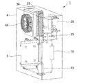
図1に示す冷却装置1は、高密度の熱源である被冷却物2を冷却するためのもので、被冷却物2と接触する冷却プレート3を備えている。被冷却物2の熱は、伝導によって冷却プレート3に伝達される。また、この冷却装置1は、冷却プレート3を除く他の構成部品を囲む筐体4(図2参照)を備えている。
Hereinafter, an embodiment of a cooling device according to the present invention will be described in detail with reference to FIGS.
A
冷却プレート3は、図2および図3に示すように、熱伝導率が高い金属によって板状に形成されており、主面が水平方向を指向する状態で筐体4の下部に立てて配置されている。この冷却プレート3は、筐体4の一側部に露出している。また、この冷却プレート3は、温度センサ5(図1参照)を備えている。温度センサ5は、冷却プレート3の温度を信号として後述する制御装置6に送る。この実施の形態においては、この冷却プレート3によって、本発明でいう「吸熱部材」が構成されている。
As shown in FIGS. 2 and 3, the
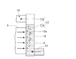
この冷却プレート3の内部には、冷媒室11が形成されている。この冷媒室11の中には液状の第1の冷媒12(図1参照)が溜められている。この実施の形態による第1の冷媒12は、代替フロン(HFC−134a)である。なお、第1の冷媒12の種類は、代替フロンに限定されることはなく、例えばアンモニアや水でもよい。水を使用する場合は、沸点を下げるために冷媒室11内を減圧させる。
A
冷却プレート3に被冷却物2から伝達された熱は、図5に模式的に示すように、冷媒室11内の液状の第1の冷媒12に伝達され、この第1の冷媒12を加熱する。この液状の第1の冷媒12は、温度が上昇することにより沸騰して気化し、冷媒ガス12aになる。すなわち、冷却プレート3は、第1の冷媒12が気化するときの気化潜熱に相当する熱エネルギーが奪われて冷却される。このように冷却プレート3が第1の冷媒12によって冷却されることにより、被冷却物2が冷却される。気化潜熱を利用して冷却することにより奪われる熱エネルギーは、冷却が顕熱反応である場合と較べて多くなる。
The heat transferred from the object to be cooled 2 to the
冷媒ガス12aは、液状の第1の冷媒12より比重が小さいために、冷媒室11内で上昇する。この冷媒室11内は、液状の第1の冷媒12が溜められた冷媒液体層11aと、冷媒ガス12aが溜められた冷媒気体層11bとに分けられる。冷媒室11内の冷媒ガス12aは、冷媒室11の上端部から後述する第2の冷媒通路14に流出する。
The
冷却プレート3の冷媒室11の下端部は、図1に示すように、第1の冷媒通路15によって気液分離器16の下端部に接続されている。第1の冷媒通路15は、図3に示すように、複数の管部材17によって形成されている。
気液分離器16は、ガス状の第1の冷媒12と液状の第1の冷媒12とを分離させる気液分離室18を有しており、図2および図3に示すように、冷却プレート3と水平方向に隣り合う位置に配置されている。
As shown in FIG. 1, the lower end portion of the
The gas-
この実施の形態による気液分離器16は、その上端部が冷却プレート3の上端部と同じ高さに位置する状態で設置されている。この気液分離器16と冷却プレート3とに貯留されている液状の冷媒の液面は、図1に示すように、冷却プレート3の上部であって、被冷却物2と接触する部位より上に位置している。冷却プレート3内の第1の冷媒12が気化して冷媒室11から流出したときは、気液分離器16内から新たに第1の冷媒12が冷媒室11に補充される。
The gas-
気液分離器16(気液分離室18)の上端部は、第2の冷媒通路14を介して冷却プレート3(冷媒室11)の上端部に接続されている。
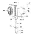
第2の冷媒通路14は、冷却プレート3の上端部に接続された複数の管部材21(図3参照)からなる上流側管路22と、気液分離器16の上端部に接続された複数の管部材23からなる下流側管路24と、これら両管路22,24どうしの間に設けられた第1の凝縮器25および熱交換器26などによって構成されている。
The upper end portion of the gas-liquid separator 16 (gas-liquid separation chamber 18) is connected to the upper end portion of the cooling plate 3 (refrigerant chamber 11) via the second
The second
第1の凝縮器25は、第2の冷媒通路14を流れる第1の冷媒12を大気によって冷却するもので、図3に示すように、第1の冷媒12が流れるパイプ27と冷却フィン(図示せず)とを有している。パイプ27は、第1の凝縮器25の内部を水平方向に横切る複数の冷却部(図示せず)と、これらの冷却部どうしを接続する屈曲部27aとによって形成されている。第1の凝縮器25の上端部に位置するパイプ27の上流側端部が上流側管路22に接続されている。また、第1の凝縮器25の下端部に位置するパイプ27の下流側端部が下流側管路24に接続されている。この実施の形態による第1の冷媒12は、第1の凝縮器25内で大気によって冷却されて液化するものが用いられている。
The
この第1の凝縮器25は、図2および図3に示すように、第2の冷媒通路14の途中であって、冷却プレート3よび気液分離器16より高い位置に設けられている。このため、第1の凝縮器25で冷却されて液化した第1の冷媒12は、重力によって下流側管路24を通って気液分離器16に流れ下りる。
As shown in FIGS. 2 and 3, the
熱交換器26は、図1に示すように、第2の冷媒通路14に第1の凝縮器25と並列に設けられて第1の冷媒12が流れる第1の冷媒部28と、第1の冷媒12とは異なる第2の冷媒(図示せず)が流れる第2の冷媒部29とを有している。第2の冷媒は、第1の冷媒12と同等のもので、後述する第3の冷媒通路31に封入されている。すなわち、熱交換器26は、第2の冷媒通路14に第1の凝縮器25と並列に設けられているとともに、第3の冷媒通路31の途中に設けられている。
熱交換器26の第1の冷媒部28と第2の冷媒部29は、第1の冷媒12の熱を第2の冷媒に伝達させる機能を有している。
以下においては、冷却プレート3と、気液分離器16と、第1の凝縮器25と、熱交換器26などの第1の冷媒12が通る部位を単に「自然循環サイクル部32」という。
As shown in FIG. 1, the
The first
Hereinafter, a portion through which the first refrigerant 12 such as the
熱交換器26の第2の冷媒部29は、第2の冷媒を用いる冷凍サイクルの気化行程が行われるものである。冷凍サイクルは、第3の冷媒通路31における熱交換器26より下流側に位置するコンプレッサ33によって行われる圧縮行程と、このコンプレッサ33より下流側に設けられた第2の凝縮器34によって行われる冷却工程と、この第2の凝縮器34と熱交換機との間に設けられた電子膨張弁35によって行われる膨張行程と、上述した熱交換器26の第2の冷媒部29で行われる気化行程などによって構成されている。
The second
第2の冷媒部29の下流側端部は、熱交換器26の上端部に位置しており、図4に示すように、複数の管部材36からなる第1の管路37によってコンプレッサ33の冷媒入口部33aに接続されている。コンプレッサ33の冷媒出口部33bは、複数の管部材38からなる第2の管路39によって第2の凝縮器34の上端部に接続されている。
The downstream end portion of the second
コンプレッサ33は、図示していないモータによって駆動されることにより第2の冷媒を圧縮して第2の管路39に吐出する。このコンプレッサ33は、回転軸の回転を検出するセンサを備えていない、いわゆるセンサレスのものである。コンプレッサ駆動用のモータは、コンプレッサハウジング40の内部に収容されている。このモータの動作(コンプレッサの回転)は、後述する制御装置6によって制御される。
The
第2の凝縮器34は、コンプレッサ33から吐出された第2の冷媒を大気によって冷却するもので、第2の冷媒が流れるパイプ41と冷却フィン(図示せず)とを有している。第2の冷媒は、第2の凝縮器34によって冷却されることにより液化される。第2の凝縮器34のパイプ41は、第2の凝縮器34の内部を水平方向に横切る複数の冷却部(図示せず)と、これらの冷却部どうしを接続する屈曲部41aとによって形成されている。第2の凝縮器34の上端部に位置するパイプの上流側端部が第2の管路39に接続されている。また、第2の凝縮器34の下端部に位置するパイプ41の下流側端部は、複数の管部材42からなる第3の管路43と電子膨張弁35とを介して熱交換器26の下端部(第2の冷媒部29の上流側端部)に接続されている。
The
この実施の形態による第2の凝縮器34は、図2に示すように、上述した第1の凝縮器25と水平方向に並べて設置されている。また、第2の凝縮器34を挟んで第1の凝縮器25とは反対側には、第1および第2の凝縮器25,34に大気を吹き付ける電動式の冷却ファン44が配置されている。この冷却ファン44の動作は、制御装置6によって制御される。
電子膨脹弁35は、第2の凝縮器34によって冷却されて液化した第2の冷媒を減圧させる。電子膨脹弁35で減圧された第2の冷媒は、熱交換器26内で気化され、気化するときの気化潜熱に相当する熱エネルギーを第1の冷媒部28から奪う。このため、熱交換器26内の第1の冷媒部28を流れる第1の冷媒12は、熱交換器26内で冷却されて液化され、重力によって下流側管路24を通って気液分離器16に流れ下りる。
以下においては、熱交換器26と、コンプレッサ33と、第2の凝縮器34および電子膨脹弁35などの第2の冷媒が通る部位を単に「冷凍サイクル部45」という。
As shown in FIG. 2, the
The
Hereinafter, a portion through which the second refrigerant such as the
制御装置6は、後述する複数の機能部を有し、コンプレッサ33が停止している第1の運転形態と、コンプレッサ33が運転されている第2の運転形態とを切替える構成が採られている。第1の運転形態が採られると、自然循環サイクル部32のみによって冷却が行われる。第2の運転形態が採られると、自然循環サイクル部32と、冷凍サイクル部45との両方を使用して冷却が行われる。
The
制御装置6の複数の機能部とは、図1に示すように、膨張弁制御部51と、冷却ファン制御部52と、温度設定部53と、インバータ制御部54である。膨張弁制御部51は、電子膨脹弁35の開度を制御する。冷却ファン制御部52は、冷却ファン44のオン、オフを切替える。温度設定部53は、作業者(図示せず)が目標とする冷却温度を設定するためのものである。
The plurality of functional units of the
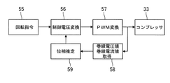
インバータ制御部54は、図6に示すように、回転指令部55と、制御電圧変換部56と、PWM変換部57と、巻線電圧値および巻線電流値取得部58と、位相推定部59などを備え、コンプレッサ駆動用モータの回転、停止および回転速度(周波数)の上昇、低下などの動作を制御する。
As shown in FIG. 6, the
次に、上述したように構成された冷却装置1の動作を制御装置6の動作説明を含めて図7に示すフローチャートを用いて説明する。
この実施の形態による冷却装置1は、ステップS1においてメインスイッチ(図示せず)がOFF状態からON状態に移行することにより、動作を開始する。制御装置6は、メインスイッチがON状態となることにより起動する。
制御装置6は、起動後にステップS1において、電子膨脹弁35の開度を所定の開度に設定するとともに、冷却ファン44を回転させる。また、制御装置6は、ステップS1においては、コンプレッサ駆動用モータを停止した状態に保つ。すなわち、運転開始時は、自然循環サイクル部32のみを使用する第1の運転形態で冷却装置1が運転される。このように冷却装置1が第1の運転形態で運転されている状態で冷却プレート3に被冷却物2が接触させられる。
Next, the operation of the
The
The
次に、制御装置6は、ステップS2において、現在の冷却プレート3の温度が予め定めた設定温度より高いか否かを判別する。この設定温度は、作業者が温度設定部53によって設定した目標とする温度である。冷却プレート3の温度が設定温度より低い場合、制御装置6は、ステップS3において、コンプレッサ33が動作しているか否かを判別する。コンプレッサ33が動作していない場合は、ステップS2に戻って上述した制御フローが繰り返される。すなわち、第1の運転形態で被冷却物2を充分に冷却できる場合は、ステップS2とステップS3とを繰り返し、自然循環サイクル部32のみによって冷却されることになる。
Next, in step S2, the
第1の運転形態が採られているときは、冷却プレート3の冷媒室11内で生じた冷媒ガス12aが主に第1の凝縮器25で冷却される。第1の冷媒12は、第1の凝縮器25内で一部あるいは大部分が液化し、重力によって気液分離器16の気液分離室18に流下する。液状の第1の冷媒12とガス状の第1の冷媒12は、気液分離器16室内で分離される。
When the first operation mode is adopted, the
液状の第1の冷媒12は、冷却プレート3内の第1の冷媒12が減少したときに、重力によって気液分離器16から第1の冷媒通路15を通って冷却プレート3の冷媒室11に流入する。このため、第1の運転形態において、第1の冷媒12は、循環用のポンプを使用することなく、自然循環サイクル部32を循環する。この冷却装置1において、第1の冷媒12がこのように循環するために必要な電力は、冷却ファン44を駆動するための電力のみである。
第1の凝縮器25は大気によって第1の冷媒12を冷却するものである。このため、この冷却装置1は、第1の冷却形態では第1の冷媒12の温度が大気温度以下になることはないから、結露が生じ難いものである。
When the first refrigerant 12 in the
The
ステップS2において、冷却プレート3の温度が設定温度より高いと判別された場合、制御装置6は、ステップS4において、コンプレッサ33が動作しているか否かを判別する。このとき、コンプレッサ33が動作していない場合は、ステップS5に進み、制御装置6がコンプレッサ33を始動させる。コンプレッサ33の始動時の回転数は、予め定めた最低回転数Minである。コンプレッサ33が動作を開始することによって、第1の運転形態から第2の運転形態に移行し、自然循環サイクル部32と冷凍サイクル部45との両方によって冷却が行われる。
When it is determined in step S2 that the temperature of the
制御装置6は、コンプレッサ33を始動させた後にステップS6においてインバータ最適化制御を行う。このインバータ最適化制御とは、コンプレッサ駆動用モータの回転を安定させる制御である。
コンプレッサ33が運転されることにより、コンプレッサ33から第3の冷媒通路31に吐出された第2の冷媒が第2の凝縮器34で冷却され、さらに、電子膨脹弁35を通って熱交換器26内の第2の冷媒部29で気化する。熱交換器26内で第2の冷媒部29と隣り合う位置には、第1の冷媒部28が存在している。このため、熱交換器26内において、第2の冷媒が気化するときの気化潜熱に相当する熱エネルギーが、第1の冷媒部28を流れている第1の冷媒12から奪われる。すなわち、熱交換器26内で第1の冷媒12が冷却される。このため、第2の運転形態が採られることにより、第1の冷媒12の液化および冷却が促進され、冷却プレート3の冷却能力が高くなる。
The
By operating the
第2の運転形態が採られてコンプレッサ33が運転されている状態でも冷却プレート3の温度が設定温度より高い場合は、ステップS2からステップS4を経てステップS7に進み、制御装置6がコンプレッサ駆動用モータを駆動するための周波数を上げる。すなわち、コンプレッサ33が運転されている状態で冷却プレート3の温度が設定温度より高い場合は、コンプレッサ33の回転数が徐々に増大する。
If the temperature of the
一方、ステップS2で冷却プレート3の温度が設定温度以下であると判別された場合、制御装置6は、ステップS2からステップS3を経てステップS8に進み、コンプレッサ駆動用モータを駆動するための周波数が最低値であるか否かを判別する。この周波数が最低値ではない場合、制御装置6は、ステップS9において、コンプレッサ駆動用モータを駆動するための周波数を下げる。すなわち、コンプレッサ33が運転されている状態で冷却プレート3の温度が設定温度以下である場合は、コンプレッサ33の回転数が徐々に低下する。
On the other hand, when it is determined in step S2 that the temperature of the
ステップS8で周波数が最低値であると判別された場合は、ステップS10において、制御装置6がコンプレッサ駆動用モータを停止させる。すなわち、制御装置6は、温度センサ5によって検出された冷却プレート3の温度が予め定めた設定温度以下である場合は、コンプレッサ33を停止させ、かつ冷却プレート3の温度が設定温度より高い場合には、コンプレッサ33を運転状態とする機能を有している。
If it is determined in step S8 that the frequency is the lowest value, the
この実施の形態による冷却装置1を試作して実際に動作させたところ、図8〜図10に示すような結果が得られた。図8(A)は、この実施の形態による冷却装置1の第1の運転形態のとき(自然循環サイクル部32のみによって冷却を行ったとき)の能力と、第2の運転形態のとき(冷凍サイクル部45も動作させて冷却を行ったとき)の能力とを示す。図8(B)は、チラー装置の冷却能力を示す。図8(C)は、図8(A)と図8(B)とを重ねたものである。図8(A)〜(C)の縦軸はヒータ負荷であり、横軸は冷却プレ−トと周囲の温度との温度差である。また、図8(A)〜(C)中には、COP(成績係数)が記載されている。COPは、冷却能力を消費電力で除して求めることができる。
When the
図8(B)から分かるように、チラー装置のCOPは低く、冷却能力と消費電力の比が3倍程度である。
しかし、この実施の形態による冷却装置1によれば、冷却プレート3との温度が周囲温度との温度差を許容できるのであれば、大きくCOPを向上させることが可能である。
図8(C)から分かるように、自然循環サイクル部32のみの動作では冷却能力が不足する場合には、インバータ制御されたコンプレッサ33を有する冷凍サイクル部45を動作させることにより、チラー装置と同等の冷却能力を得ることができる。この際、チラー装置と比較して大きくCOPを向上させることができ、省エネ効果が得られる。
As can be seen from FIG. 8B, the COP of the chiller device is low, and the ratio of the cooling capacity to the power consumption is about three times.
However, according to the
As can be seen from FIG. 8 (C), when the cooling capacity is insufficient by the operation of only the natural
この実施の形態による冷却装置1の冷凍サイクル部45とチラー装置の1次側サイクル部は、ともにコンプレッサを用いる構成が採られているが、チラー装置の2次側サイクル部は冷却された水を送るためにポンプが必要である。この実施の形態による冷却装置1の自然循環部に用いられている冷却ファン44の消費電力は。ポンプの消費電力より少ない。すなわち、チラー装置は、この消費電力の差分だけ、この実施の形態による冷却装置1と較べて電力消費が多くなる。
この実施の形態による冷却装置1は、冷却プレート3の温度と周囲温度との差を許容できるほど自然循環サイクル部32の冷却能力が得られ、冷凍サイクル部45のコンプレッサ33の回転速度を低く抑えることができるため、大きな省エネ効果が得られる。
The
In the
図9は、この実施の形態による自然循環サイクル部32で冷却を行った場合とヒートシンク(図示せず)を使用して冷却を行った場合の冷却速度を比較したグラフである。ヒートシンクを使用して冷却するにあたっては、この実施の形態で用いた冷却ファン44と同等の性能の冷却ファンでヒートシンクに大気を吹き付けて行った。
図9から分かるように、100℃の冷却プレート3を50℃まで冷却させるために必要な時間は、自然循環サイクル部32で約8秒、ヒートシンクで約18秒必要であった。自然循環サイクル部32の冷却速度は、ヒートシンクの冷却速度の2倍以上であった。
FIG. 9 is a graph comparing the cooling rate when cooling is performed in the natural
As can be seen from FIG. 9, the time required for cooling the
図10は、この実施の形態による自然循環サイクル部32で冷却を行った場合と、チラー装置によって周囲温度の水で冷却する場合と、ファンで周囲温度に冷却された水をポンプで循環して冷却する場合とについて冷却速度を比較したグラフである。
図10から分かるように、これらの3つの冷却方式の冷却速度は同等であった。このことは、この実施の形態による自然循環サイクル部32は、水冷と同等の冷却速度で冷却でき、しかも、消費電力がこれらの3つの冷却方式のなかで最も少ないことを意味する。
FIG. 10 shows a case where cooling is performed by the natural
As can be seen from FIG. 10, the cooling rates of these three cooling systems were equivalent. This means that the natural
上述したように構成されたこの実施の形態による冷却装置1において、冷却プレート3が気化潜熱を利用して冷却することにより奪われる熱エネルギーは、冷却が顕熱反応である場合と較べて多くなる。また、このように気化潜熱を利用して冷却が行われることにより、冷却プレート3を均一に冷却することが可能になる。水で顕熱反応によって冷却する場合には、入口から流入した低温の水が出口に到達するときには温度が相対的に高い水になる。このため、入口側と出口側では温度差が生じることになる。しかし、気化潜熱を利用して冷却が行われると、冷媒が冷却プレート3内で略均等に蒸発するため、上述したように冷却プレート3の温度分布が略均等になる。
すなわち、この冷却装置1によれば、冷却水を使用して冷却する場合より効率よく冷却することができる。
第1の凝縮器25は、大気によって第1の冷媒12を冷却するものである。このため、この冷却装置1は、第1の冷却形態では第1の冷媒12の温度が大気温度以下になることはないから、結露が生じ難いものである。
In the
That is, according to this
The
このため、この冷却装置1によれば、第1の運転形態を採ることにより、少ない消費電力でかつ冷却水を使用する場合と較べて高効率の冷却を行うことが可能で、しかも、結露が生じることなく冷却を行うことができる。第1の運転形態では冷却能力が不足する場合には、第2の運転形態を採ることによって、冷却能力の不足分を補うことができる。第2の運転形態ではコンプレッサ33が運転されて消費電力が増大する。しかし、消費電力は、例えばチラー装置のように常にコンプレッサが運転されている従来の冷却装置より少なくなる。
したがって、この実施の形態によれば、結露を防止しながら高い冷却能力が得られ、しかも、消費電力が少なくなる冷却装置を提供することができる。
For this reason, according to this
Therefore, according to this embodiment, it is possible to provide a cooling device that can obtain a high cooling capacity while preventing condensation and that consumes less power.
この実施の形態による冷却装置1は、冷却プレート3の温度を検出する温度センサ5を備えている。制御装置6は、この温度センサ5によって検出された冷却プレート3の温度が予め定めた設定温度(目標温度)以下である場合は、コンプレッサ33を停止させ、かつ冷却プレート3の温度が設定温度(目標温度)より高い場合には、コンプレッサ33を運転状態とする機能を有している。
このため、この実施の形態によれば,第1の運転形態と第2の運転形態とが自動で切り替わるから電力消費を可及的少なく抑えながら被冷却物2を冷却することができる。
The
For this reason, according to this embodiment, since the 1st operation form and the 2nd operation form change automatically, the to-
この実施の形態による制御装置6は、温度センサ5によって検出された冷却プレート3の温度が設定温度(目標温度)より高い場合に、コンプレッサ33の回転数を徐々に上昇させる機能と、温度センサ5によって検出された冷却プレート3の温度が設定温度(目標温度)以下である場合に、コンプレッサ33の回転数を徐々に低下させる機能とを有している。
このため、この実施の形態によれば、被冷却物2の温度に応じてコンプレッサ33の回転数が変化するから、電力消費量が必要最小限になる。
The
For this reason, according to this embodiment, since the rotation speed of the
この実施の形態よる第1の凝縮器25は、第1の冷媒通路14に大気を吹き付ける冷却ファン44を備えている。このため、第1の冷媒12を冷却する効率が高くなるから、より一層冷却効率が高くなる冷却装置を提供できる。また、小型の第1の凝縮器25を使用できるから、コンパクトな冷却装置を実現できるという効果もある。
The
この実施の形態による第1の冷媒12および第2の冷媒は代替フロンである。このため、冷却水を使用する場合とは異なり、第1および第2の冷媒12が漏洩したとしても電気機器に不具合が生じることはない。したがって、この実施の形態によれば、使用する場所に制約を受けることがない冷却装置を提供することができる。
The
1…冷却装置、2…被冷却物、3…冷却プレート(吸熱部材)、5…温度センサ(センサ)、6…制御装置、11…冷媒室、12…第1の冷媒、12a…冷媒ガス(ガス状の第1の冷媒)、14…第2の冷媒通路、15…第1の冷媒通路、16…気液分離器、18…気液分離室、25…第1の凝縮器、26…熱交換器、31…第2の冷媒通路、33…コンプレッサ、34…第2の凝縮器、35…電子膨脹弁、44…冷却ファン(ファン)。
DESCRIPTION OF
Claims (5)
ガス状の前記第1の冷媒と液状の前記第1の冷媒とを分離させる気液分離室を有する気液分離器と、
前記冷媒室の下端部と前記気液分離室の下端部とを接続する第1の冷媒通路と、
前記冷媒室の上端部と前記気液分離室の上端部とを接続する第2の冷媒通路と、
前記第2の冷媒通路の途中であって、前記吸熱部材および前記気液分離器より高い位置に設けられ、前記第1の冷媒を大気によって冷却する第1の凝縮器と、
前記第2の冷媒通路に前記第1の凝縮器と並列に設けられているとともに、前記第1の冷媒とは異なる第2の冷媒が流れる第3の冷媒通路の途中に設けられ、前記第1の冷媒の熱を前記第2の冷媒に伝達させる熱交換器と、
前記第3の冷媒通路における前記熱交換器より下流側に設けられ、前記第2の冷媒を圧縮するコンプレッサと、
前記第3の冷媒通路における前記コンプレッサより下流側に設けられ、前記コンプレッサから吐出された第2の冷媒を冷却する第2の凝縮器と、
前記第3の冷媒通路における第2の凝縮器と前記熱交換器との間に設けられた膨張弁と、
前記コンプレッサの回転を制御する制御装置とを備え、
前記第1の冷媒は、前記冷媒室内で被冷却物の熱によって加熱されることにより気化しかつ前記第1の凝縮器内で大気によって冷却されて液化するものであり、
前記第2の冷媒は、第2の凝縮器で冷却されることにより液化し、前記膨張弁を通って膨張して熱交換器内で気化されるものであることを特徴とする冷却装置。 A heat-absorbing member having a refrigerant chamber through which the first refrigerant flows, to which heat of the object to be cooled is transmitted;
A gas-liquid separator having a gas-liquid separation chamber for separating the gaseous first refrigerant and the liquid first refrigerant;
A first refrigerant passage connecting the lower end of the refrigerant chamber and the lower end of the gas-liquid separation chamber;
A second refrigerant passage connecting the upper end of the refrigerant chamber and the upper end of the gas-liquid separation chamber;
A first condenser that is provided in the middle of the second refrigerant passage and is higher than the heat absorbing member and the gas-liquid separator, and cools the first refrigerant by the atmosphere;
The first refrigerant passage is provided in parallel with the first condenser, and is provided in the middle of a third refrigerant passage through which a second refrigerant different from the first refrigerant flows. A heat exchanger for transferring the heat of the refrigerant to the second refrigerant;
A compressor provided on the downstream side of the heat exchanger in the third refrigerant passage, and compresses the second refrigerant;
A second condenser that is provided downstream of the compressor in the third refrigerant passage and cools the second refrigerant discharged from the compressor;
An expansion valve provided between the second condenser and the heat exchanger in the third refrigerant passage;
A control device for controlling the rotation of the compressor,
The first refrigerant is vaporized by being heated by the heat of the object to be cooled in the refrigerant chamber, and is cooled and liquefied by the atmosphere in the first condenser.
The cooling device, wherein the second refrigerant is liquefied by being cooled by a second condenser, is expanded through the expansion valve, and is vaporized in a heat exchanger.
さらに、前記吸熱部材の温度を検出するセンサを備え、
前記制御装置は、
前記センサによって検出された前記吸熱部材の温度が予め定めた設定温度以下である場合は、前記コンプレッサを停止させ、かつ前記吸熱部材の温度が前記設定温度より高い場合には、前記コンプレッサを運転状態とする機能を有していることを特徴とする冷却装置。 The cooling device according to claim 1, wherein
And a sensor for detecting the temperature of the heat absorbing member.
The control device includes:
When the temperature of the heat absorbing member detected by the sensor is equal to or lower than a preset temperature, the compressor is stopped, and when the temperature of the heat absorbing member is higher than the set temperature, the compressor is in an operating state. A cooling device having a function of
前記制御装置は、
前記センサによって検出された前記吸熱部材の温度が前記設定温度より高い場合に、前記コンプレッサの回転数を徐々に上昇させる機能と、
前記センサによって検出された前記吸熱部材の温度が前記設定温度以下である場合に、前記コンプレッサの回転数を徐々に低下させる機能とを有していることを特徴とする冷却装置。 The cooling device according to claim 2, wherein
The control device includes:
A function of gradually increasing the rotational speed of the compressor when the temperature of the heat absorbing member detected by the sensor is higher than the set temperature;
The cooling device having a function of gradually decreasing the rotational speed of the compressor when the temperature of the heat absorbing member detected by the sensor is equal to or lower than the set temperature.
さらに、前記第2の冷媒通路に大気を吹き付けるファンを備えていることを特徴とする冷却装置。 The cooling device according to any one of claims 1 to 3,
The cooling apparatus further comprises a fan that blows air to the second refrigerant passage.
前記第1の冷媒および前記第2の冷媒は代替フロンであることを特徴とする冷却装置。 In the cooling device according to any one of claims 1 to 4,
The cooling device, wherein the first refrigerant and the second refrigerant are alternative chlorofluorocarbons.
Priority Applications (1)
| Application Number | Priority Date | Filing Date | Title |
|---|---|---|---|
| JP2015028556A JP6423736B2 (en) | 2015-02-17 | 2015-02-17 | Cooling system |
Applications Claiming Priority (1)
| Application Number | Priority Date | Filing Date | Title |
|---|---|---|---|
| JP2015028556A JP6423736B2 (en) | 2015-02-17 | 2015-02-17 | Cooling system |
Publications (2)
| Publication Number | Publication Date |
|---|---|
| JP2016151374A JP2016151374A (en) | 2016-08-22 |
| JP6423736B2 true JP6423736B2 (en) | 2018-11-14 |
Family
ID=56696323
Family Applications (1)
| Application Number | Title | Priority Date | Filing Date |
|---|---|---|---|
| JP2015028556A Active JP6423736B2 (en) | 2015-02-17 | 2015-02-17 | Cooling system |
Country Status (1)
| Country | Link |
|---|---|
| JP (1) | JP6423736B2 (en) |
Families Citing this family (4)
| Publication number | Priority date | Publication date | Assignee | Title |
|---|---|---|---|---|
| CN109477696B (en) * | 2016-09-09 | 2021-04-09 | 株式会社电装 | Equipment temperature adjusting device |
| JP6734935B2 (en) | 2016-12-19 | 2020-08-05 | 日立オートモティブシステムズ株式会社 | Cooling device controller |
| JP6992411B2 (en) * | 2017-11-01 | 2022-01-13 | 株式会社デンソー | Equipment cooling device |
| DE102022122589A1 (en) | 2022-09-06 | 2024-03-07 | Lauda Dr. R. Wobser Gmbh & Co. Kg | Refrigeration system and method for operating a refrigeration system |
Family Cites Families (5)
| Publication number | Priority date | Publication date | Assignee | Title |
|---|---|---|---|---|
| JP4043074B2 (en) * | 1997-06-27 | 2008-02-06 | 三菱重工業株式会社 | Refrigeration equipment |
| JP3576938B2 (en) * | 2000-07-31 | 2004-10-13 | 共立冷熱株式会社 | heat pump |
| JP2002243290A (en) * | 2001-02-16 | 2002-08-28 | Sanden Corp | Refrigeration unit |
| JP4318567B2 (en) * | 2004-03-03 | 2009-08-26 | 三菱電機株式会社 | Cooling system |
| JP2011162151A (en) * | 2010-02-15 | 2011-08-25 | Toyota Motor Corp | Cooling system for vehicle |
-
2015
- 2015-02-17 JP JP2015028556A patent/JP6423736B2/en active Active
Also Published As
| Publication number | Publication date |
|---|---|
| JP2016151374A (en) | 2016-08-22 |
Similar Documents
| Publication | Publication Date | Title |
|---|---|---|
| JP5750304B2 (en) | Electronic equipment cooling system | |
| US20170184314A1 (en) | Heat pump heating system | |
| US20200254845A1 (en) | Equipment cooling device | |
| JP6423736B2 (en) | Cooling system | |
| JP2010190553A (en) | Cooling system for electronic apparatus | |
| JP2006517643A (en) | Supercritical pressure regulation of vapor compression system | |
| WO2018055926A1 (en) | Device temperature adjusting apparatus | |
| JP5667956B2 (en) | Air conditioner | |
| JP5984490B2 (en) | Heat pump equipment | |
| EP3191773B1 (en) | Chiller compressor oil conditioning | |
| JP5950010B1 (en) | Heat pump steam generator | |
| JP2019211182A (en) | Cooling device and compression unit | |
| JP2008082601A (en) | Heat pump hot water supply device | |
| JP4665736B2 (en) | Control method for refrigeration cycle apparatus and refrigeration cycle apparatus using the same | |
| US20210368648A1 (en) | Cooling device, control method, and storage medium | |
| JP5836844B2 (en) | Refrigeration equipment | |
| WO2017169925A1 (en) | Cooling system and cooling method | |
| WO2018163347A1 (en) | Geothermal heat pump device | |
| JP2018146144A (en) | Refrigeration cycle device and operating method for the same | |
| JP6455752B2 (en) | Refrigeration system | |
| JP2006038386A (en) | Cooling device | |
| KR100909726B1 (en) | Refrigerator Cooling Unit and Cooling Method | |
| KR20110100415A (en) | Refrigerator using a thermoelectric element | |
| JP6341481B2 (en) | Refrigeration system | |
| JP2013257105A (en) | Refrigeration cycle device and hot water generating device having the same |
Legal Events
| Date | Code | Title | Description |
|---|---|---|---|
| A621 | Written request for application examination |
Free format text: JAPANESE INTERMEDIATE CODE: A621 Effective date: 20171201 |
|
| A977 | Report on retrieval |
Free format text: JAPANESE INTERMEDIATE CODE: A971007 Effective date: 20180830 |
|
| TRDD | Decision of grant or rejection written | ||
| A01 | Written decision to grant a patent or to grant a registration (utility model) |
Free format text: JAPANESE INTERMEDIATE CODE: A01 Effective date: 20181002 |
|
| A61 | First payment of annual fees (during grant procedure) |
Free format text: JAPANESE INTERMEDIATE CODE: A61 Effective date: 20181019 |
|
| R150 | Certificate of patent or registration of utility model |
Ref document number: 6423736 Country of ref document: JP Free format text: JAPANESE INTERMEDIATE CODE: R150 |
|
| R250 | Receipt of annual fees |
Free format text: JAPANESE INTERMEDIATE CODE: R250 |