JP4665736B2 - Control method for refrigeration cycle apparatus and refrigeration cycle apparatus using the same - Google Patents
Control method for refrigeration cycle apparatus and refrigeration cycle apparatus using the same Download PDFInfo
- Publication number
- JP4665736B2 JP4665736B2 JP2005345487A JP2005345487A JP4665736B2 JP 4665736 B2 JP4665736 B2 JP 4665736B2 JP 2005345487 A JP2005345487 A JP 2005345487A JP 2005345487 A JP2005345487 A JP 2005345487A JP 4665736 B2 JP4665736 B2 JP 4665736B2
- Authority
- JP
- Japan
- Prior art keywords
- expansion mechanism
- target
- rotation speed
- refrigeration cycle
- temperature
- Prior art date
- Legal status (The legal status is an assumption and is not a legal conclusion. Google has not performed a legal analysis and makes no representation as to the accuracy of the status listed.)
- Expired - Fee Related
Links
- 238000005057 refrigeration Methods 0.000 title claims description 73
- 238000000034 method Methods 0.000 title claims description 30
- 230000006835 compression Effects 0.000 claims description 83
- 238000007906 compression Methods 0.000 claims description 83
- 239000012530 fluid Substances 0.000 claims description 40
- 239000003507 refrigerant Substances 0.000 claims description 23
- CURLTUGMZLYLDI-UHFFFAOYSA-N Carbon dioxide Chemical group O=C=O CURLTUGMZLYLDI-UHFFFAOYSA-N 0.000 claims description 4
- 230000003213 activating effect Effects 0.000 claims description 3
- 229910002092 carbon dioxide Inorganic materials 0.000 claims description 2
- 239000001569 carbon dioxide Substances 0.000 claims description 2
- XLYOFNOQVPJJNP-UHFFFAOYSA-N water Substances O XLYOFNOQVPJJNP-UHFFFAOYSA-N 0.000 description 62
- 238000001514 detection method Methods 0.000 description 19
- 238000009835 boiling Methods 0.000 description 9
- 238000013459 approach Methods 0.000 description 8
- 230000003247 decreasing effect Effects 0.000 description 4
- 230000000694 effects Effects 0.000 description 4
- 230000004913 activation Effects 0.000 description 2
- 239000002826 coolant Substances 0.000 description 2
- 239000007788 liquid Substances 0.000 description 2
- 238000004904 shortening Methods 0.000 description 2
- 230000005494 condensation Effects 0.000 description 1
- 238000009833 condensation Methods 0.000 description 1
- 238000010586 diagram Methods 0.000 description 1
- 238000010438 heat treatment Methods 0.000 description 1
- 239000010687 lubricating oil Substances 0.000 description 1
Images


Classifications
-
- F—MECHANICAL ENGINEERING; LIGHTING; HEATING; WEAPONS; BLASTING
- F25—REFRIGERATION OR COOLING; COMBINED HEATING AND REFRIGERATION SYSTEMS; HEAT PUMP SYSTEMS; MANUFACTURE OR STORAGE OF ICE; LIQUEFACTION SOLIDIFICATION OF GASES
- F25B—REFRIGERATION MACHINES, PLANTS OR SYSTEMS; COMBINED HEATING AND REFRIGERATION SYSTEMS; HEAT PUMP SYSTEMS
- F25B9/00—Compression machines, plants or systems, in which the refrigerant is air or other gas of low boiling point
- F25B9/06—Compression machines, plants or systems, in which the refrigerant is air or other gas of low boiling point using expanders
-
- F—MECHANICAL ENGINEERING; LIGHTING; HEATING; WEAPONS; BLASTING
- F25—REFRIGERATION OR COOLING; COMBINED HEATING AND REFRIGERATION SYSTEMS; HEAT PUMP SYSTEMS; MANUFACTURE OR STORAGE OF ICE; LIQUEFACTION SOLIDIFICATION OF GASES
- F25B—REFRIGERATION MACHINES, PLANTS OR SYSTEMS; COMBINED HEATING AND REFRIGERATION SYSTEMS; HEAT PUMP SYSTEMS
- F25B49/00—Arrangement or mounting of control or safety devices
- F25B49/02—Arrangement or mounting of control or safety devices for compression type machines, plants or systems
-
- F—MECHANICAL ENGINEERING; LIGHTING; HEATING; WEAPONS; BLASTING
- F25—REFRIGERATION OR COOLING; COMBINED HEATING AND REFRIGERATION SYSTEMS; HEAT PUMP SYSTEMS; MANUFACTURE OR STORAGE OF ICE; LIQUEFACTION SOLIDIFICATION OF GASES
- F25B—REFRIGERATION MACHINES, PLANTS OR SYSTEMS; COMBINED HEATING AND REFRIGERATION SYSTEMS; HEAT PUMP SYSTEMS
- F25B2309/00—Gas cycle refrigeration machines
- F25B2309/06—Compression machines, plants or systems characterised by the refrigerant being carbon dioxide
- F25B2309/061—Compression machines, plants or systems characterised by the refrigerant being carbon dioxide with cycle highest pressure above the supercritical pressure
-
- F—MECHANICAL ENGINEERING; LIGHTING; HEATING; WEAPONS; BLASTING
- F25—REFRIGERATION OR COOLING; COMBINED HEATING AND REFRIGERATION SYSTEMS; HEAT PUMP SYSTEMS; MANUFACTURE OR STORAGE OF ICE; LIQUEFACTION SOLIDIFICATION OF GASES
- F25B—REFRIGERATION MACHINES, PLANTS OR SYSTEMS; COMBINED HEATING AND REFRIGERATION SYSTEMS; HEAT PUMP SYSTEMS
- F25B2339/00—Details of evaporators; Details of condensers
- F25B2339/04—Details of condensers
- F25B2339/047—Water-cooled condensers
-
- F—MECHANICAL ENGINEERING; LIGHTING; HEATING; WEAPONS; BLASTING
- F25—REFRIGERATION OR COOLING; COMBINED HEATING AND REFRIGERATION SYSTEMS; HEAT PUMP SYSTEMS; MANUFACTURE OR STORAGE OF ICE; LIQUEFACTION SOLIDIFICATION OF GASES
- F25B—REFRIGERATION MACHINES, PLANTS OR SYSTEMS; COMBINED HEATING AND REFRIGERATION SYSTEMS; HEAT PUMP SYSTEMS
- F25B2400/00—General features or devices for refrigeration machines, plants or systems, combined heating and refrigeration systems or heat-pump systems, i.e. not limited to a particular subgroup of F25B
- F25B2400/14—Power generation using energy from the expansion of the refrigerant
- F25B2400/141—Power generation using energy from the expansion of the refrigerant the extracted power is not recycled back in the refrigerant circuit
-
- F—MECHANICAL ENGINEERING; LIGHTING; HEATING; WEAPONS; BLASTING
- F25—REFRIGERATION OR COOLING; COMBINED HEATING AND REFRIGERATION SYSTEMS; HEAT PUMP SYSTEMS; MANUFACTURE OR STORAGE OF ICE; LIQUEFACTION SOLIDIFICATION OF GASES
- F25B—REFRIGERATION MACHINES, PLANTS OR SYSTEMS; COMBINED HEATING AND REFRIGERATION SYSTEMS; HEAT PUMP SYSTEMS
- F25B2600/00—Control issues
- F25B2600/02—Compressor control
- F25B2600/025—Compressor control by controlling speed
-
- F—MECHANICAL ENGINEERING; LIGHTING; HEATING; WEAPONS; BLASTING
- F25—REFRIGERATION OR COOLING; COMBINED HEATING AND REFRIGERATION SYSTEMS; HEAT PUMP SYSTEMS; MANUFACTURE OR STORAGE OF ICE; LIQUEFACTION SOLIDIFICATION OF GASES
- F25B—REFRIGERATION MACHINES, PLANTS OR SYSTEMS; COMBINED HEATING AND REFRIGERATION SYSTEMS; HEAT PUMP SYSTEMS
- F25B2700/00—Sensing or detecting of parameters; Sensors therefor
- F25B2700/21—Temperatures
- F25B2700/2106—Temperatures of fresh outdoor air
-
- F—MECHANICAL ENGINEERING; LIGHTING; HEATING; WEAPONS; BLASTING
- F25—REFRIGERATION OR COOLING; COMBINED HEATING AND REFRIGERATION SYSTEMS; HEAT PUMP SYSTEMS; MANUFACTURE OR STORAGE OF ICE; LIQUEFACTION SOLIDIFICATION OF GASES
- F25B—REFRIGERATION MACHINES, PLANTS OR SYSTEMS; COMBINED HEATING AND REFRIGERATION SYSTEMS; HEAT PUMP SYSTEMS
- F25B2700/00—Sensing or detecting of parameters; Sensors therefor
- F25B2700/21—Temperatures
- F25B2700/2115—Temperatures of a compressor or the drive means therefor
- F25B2700/21152—Temperatures of a compressor or the drive means therefor at the discharge side of the compressor
-
- F—MECHANICAL ENGINEERING; LIGHTING; HEATING; WEAPONS; BLASTING
- F25—REFRIGERATION OR COOLING; COMBINED HEATING AND REFRIGERATION SYSTEMS; HEAT PUMP SYSTEMS; MANUFACTURE OR STORAGE OF ICE; LIQUEFACTION SOLIDIFICATION OF GASES
- F25B—REFRIGERATION MACHINES, PLANTS OR SYSTEMS; COMBINED HEATING AND REFRIGERATION SYSTEMS; HEAT PUMP SYSTEMS
- F25B2700/00—Sensing or detecting of parameters; Sensors therefor
- F25B2700/21—Temperatures
- F25B2700/2116—Temperatures of a condenser
- F25B2700/21161—Temperatures of a condenser of the fluid heated by the condenser
-
- F—MECHANICAL ENGINEERING; LIGHTING; HEATING; WEAPONS; BLASTING
- F25—REFRIGERATION OR COOLING; COMBINED HEATING AND REFRIGERATION SYSTEMS; HEAT PUMP SYSTEMS; MANUFACTURE OR STORAGE OF ICE; LIQUEFACTION SOLIDIFICATION OF GASES
- F25B—REFRIGERATION MACHINES, PLANTS OR SYSTEMS; COMBINED HEATING AND REFRIGERATION SYSTEMS; HEAT PUMP SYSTEMS
- F25B9/00—Compression machines, plants or systems, in which the refrigerant is air or other gas of low boiling point
- F25B9/002—Compression machines, plants or systems, in which the refrigerant is air or other gas of low boiling point characterised by the refrigerant
- F25B9/008—Compression machines, plants or systems, in which the refrigerant is air or other gas of low boiling point characterised by the refrigerant the refrigerant being carbon dioxide
Landscapes
- Engineering & Computer Science (AREA)
- Physics & Mathematics (AREA)
- Mechanical Engineering (AREA)
- Thermal Sciences (AREA)
- General Engineering & Computer Science (AREA)
- Air Conditioning Control Device (AREA)
- Compression-Type Refrigeration Machines With Reversible Cycles (AREA)
- Devices That Are Associated With Refrigeration Equipment (AREA)
- Heat-Pump Type And Storage Water Heaters (AREA)
Description
本発明は、動力を回収する膨張機構を備えた冷凍サイクル装置の制御方法およびそれを用いた冷凍サイクル装置に関する。 The present invention relates to a control method for a refrigeration cycle apparatus having an expansion mechanism for recovering power and a refrigeration cycle apparatus using the same.
減圧器の代わりに膨張機構を設けて、膨張時の圧力エネルギーを動力として回収し、COPを向上させる冷凍サイクル装置が提案されている(例えば特許文献1参照)。
上記、従来技術では、熱源側熱交換器に流入する熱源側流体の温度や利用側熱交換器に流入する利用側流体の温度が高い場合には、圧縮機構の吐出温度や高圧側圧力が上昇しやすく、機器を保護するために圧縮機構の運転を停止することが頻繁に起こるといった課題が生じていた。 In the above prior art, when the temperature of the heat source side fluid flowing into the heat source side heat exchanger or the temperature of the utilization side fluid flowing into the utilization side heat exchanger is high, the discharge temperature and the high pressure side pressure of the compression mechanism rise. There is a problem that the operation of the compression mechanism frequently stops in order to easily protect the device.
そこで、本発明は、上記課題を解決するため、膨張機構を備えた冷凍サイクル装置において、適切に膨張機構の回転数を制御し、冷凍サイクル装置を安定して運転させることを目的とし、特に、冷凍サイクル装置の起動時の安定性を向上させることを目的とする。 Then, in order to solve the above-mentioned problem, the present invention aims to control the rotation speed of the expansion mechanism appropriately in the refrigeration cycle apparatus provided with the expansion mechanism and to operate the refrigeration cycle apparatus stably. It aims at improving the stability at the time of starting of a refrigerating cycle device.
前記従来の課題を解決するために、本発明の冷凍サイクル装置の制御方法は、電動機により駆動される圧縮機構、熱源側熱交換器、発電機により動力回収を行う膨張機構、利用側熱交換器を備えた冷凍サイクル装置の起動時の制御方法であって、前記熱源側熱交換器に流入する熱源側流体温度と前記利用側熱交換器に流入する利用側流体温度の少なくとも一方の温度から決定し、前記温度が高いほど回転数が高くなるように設定された第2目標膨張機構回転数にて前記膨張機構を起動させ、前記膨張機構の回転数を所定時間、維持するとともに、前記膨張機構の起動以降に前記圧縮機構を起動させることを特徴とするものである。これによると、第2目標膨張機構回転数は外気温度、入水温度に応じて、高圧側圧力が上昇しやすい状態ほど、回転数が大きくなるように設定されているので、急激な高圧側圧力の上昇を防止でき、安定した冷凍サイクル装置の起動が実現できる。 In order to solve the above-described conventional problems, a control method for a refrigeration cycle apparatus according to the present invention includes a compression mechanism driven by an electric motor, a heat source side heat exchanger, an expansion mechanism that recovers power by a generator, and a utilization side heat exchanger. And determining from at least one of a heat source side fluid temperature flowing into the heat source side heat exchanger and a utilization side fluid temperature flowing into the utilization side heat exchanger. The expansion mechanism is activated at a second target expansion mechanism rotation speed set so that the rotation speed increases as the temperature increases, and the rotation speed of the expansion mechanism is maintained for a predetermined time. The compression mechanism is activated after the activation . According to this, the second target expansion mechanism rotational speed is set so that the rotational speed increases as the high-pressure side pressure easily rises according to the outside air temperature and the incoming water temperature. The rise can be prevented, and a stable refrigeration cycle apparatus can be started .
本発明の冷凍サイクル装置の制御方法およびそれを用いた冷凍サイクル装置は、膨張機構を備えた冷凍サイクル装置において、適切に膨張機構の回転数を制御し、冷凍サイクル装置を安定して運転させることが可能であり、特に、冷凍サイクル装置の起動時の安定性を向上させることができる。 A control method for a refrigeration cycle apparatus according to the present invention and a refrigeration cycle apparatus using the same, in a refrigeration cycle apparatus provided with an expansion mechanism, appropriately control the number of rotations of the expansion mechanism and stably operate the refrigeration cycle apparatus. In particular, it is possible to improve the stability at the start-up of the refrigeration cycle apparatus.
第1の発明は、電動機により駆動される圧縮機構、熱源側熱交換器、発電機により動力回収を行う膨張機構、利用側熱交換器を備えた冷凍サイクル装置の起動時の制御方法であって、前記熱源側熱交換器に流入する熱源側流体温度と前記利用側熱交換器に流入する利用側流体温度の少なくとも一方の温度から決定し、前記温度が高いほど回転数が高くなるように設定された第2目標膨張機構回転数にて前記膨張機構を起動させ、前記膨張機構の回転数を所定時間、維持するとともに、前記膨張機構の起動以降に前記圧縮機構を起動させるものである。第2目標膨張機構回転数は外気温度、入水温度に応じて、高圧側圧力が上昇しやすい状態ほど、回転数が大きくなるように設定されているので、急激な高圧側圧力の上昇を防止でき、安定した冷凍サイクル装置の起動が実現できる。 1st invention is the control method at the time of starting of the refrigerating cycle device provided with the compression mechanism driven by an electric motor , the heat source side heat exchanger, the expansion mechanism which collects motive power with the generator , and the use side heat exchanger , Determined from at least one of a heat source side fluid temperature flowing into the heat source side heat exchanger and a utilization side fluid temperature flowing into the utilization side heat exchanger, and set so that the number of revolutions increases as the temperature increases It has been allowed to start the hand the expansion mechanism to the second target number of revolutions of the expansion mechanism, a predetermined time the rotational speed of the expansion mechanism, while maintaining, in which activating the compression mechanism since the startup of the expansion mechanism. The second target expansion mechanism rotation speed is set so that the higher the high pressure side pressure is, the higher the rotation speed is, depending on the outside air temperature and the incoming water temperature. A stable refrigeration cycle apparatus can be activated.
第2の発明は、前記第2目標膨張機構回転数に、前記膨張機構の回転数を所定時間、維持し、さらに所定時間経過後、少なくとも前記圧縮機構の吐出温度から決定し、前記熱源側流体温度、前記利用側流体温度が高いほど回転数が高くなるように設定された第1目標膨張機構回転数となるように、前記膨張機構の回転数を制御するものである。第2目標膨張機構回転数は外気温度、入水温度に応じて、高圧側圧力が上昇しやすい状態ほど、回転数が大きくなるように設定されているので、膨張機構の回転数が第1目標膨張機構回転数へと増加する際に、急激な高圧側圧力の上昇を防止でき、安定した冷凍サイクル装置の起動が実現できる。 The second invention is the the second target number of revolutions of the expansion mechanism, the predetermined time the number of revolutions of the expansion mechanism, and maintained, to determine further after a predetermined time has elapsed, the discharge temperature of at least the compression mechanism, the heat source-side fluid The rotational speed of the expansion mechanism is controlled so that the first target expansion mechanism rotational speed is set such that the rotational speed increases as the temperature and the use-side fluid temperature increase . The second target expansion mechanism rotational speed is set so that the rotational speed increases as the pressure on the high pressure side increases more easily according to the outside air temperature and the incoming water temperature. When the rotational speed increases to the mechanism rotational speed, it is possible to prevent a rapid increase in the high-pressure side pressure and to realize a stable start-up of the refrigeration cycle apparatus.
第3の発明は、前記第2目標膨張機構回転数に、前記膨張機構の回転数を所定時間、維持し、さらに所定時間経過後、前記熱源側熱交換器に流入する熱源側流体温度と前記利用側熱交換器に流入する利用側流体温度の少なくとも一方の温度から決定し、前記第2目標膨張機構回転数より大きい値に設定された第3目標膨張機構回転数に、前記膨張機構の回転数を制御し、さらに所定経過後、前記第1目標膨張機構回転数となるように、前記膨張機構の回転数を制御するものであり、膨張機構の回転数が、第2目標膨張機構回転数から第1目標膨張機構回転数へと増加する際の急激な高圧側圧力の変化を防止でき、起動時間を短縮しつつ安定した冷凍サイクル装置の起動が実現できる。 According to a third aspect of the present invention, the rotation speed of the expansion mechanism is maintained at the second target expansion mechanism rotation speed for a predetermined time, and after a predetermined time has elapsed, the heat source side fluid temperature flowing into the heat source side heat exchanger and the The rotation of the expansion mechanism is determined based on at least one of the utilization side fluid temperatures flowing into the utilization side heat exchanger, and the third target expansion mechanism rotation speed is set to a value larger than the second target expansion mechanism rotation speed. control the number, after further predetermined lapse, so that the first target number of revolutions of the expansion mechanism, which controls the rotational speed of the expansion mechanism, the number of revolutions of the expansion mechanism is a second target number of revolutions of the expansion mechanism From this, it is possible to prevent a rapid change in the high-pressure side pressure when the rotation speed increases from the first target expansion mechanism to the first target expansion mechanism, and to realize stable start-up of the refrigeration cycle apparatus while shortening the start-up time.
第4の発明は、前記第2目標膨張機構回転数に、前記膨張機構の回転数を所定時間、維持し、さらに所定時間経過後、前記第3目標膨張機構回転数に、前記膨張機構の回転数を制御した後、予め定められた前記圧縮機構の目標吐出温度と前記圧縮機構の吐出温度との差が所定値より小さい場合に、前記第1目標膨張機構回転数となるように、前記膨張機構の回転数を制御することを特徴とするものであり、所定時間経過する以前であっても、吐出温度が目標吐出温度に近づいた場合には、膨張機構の回転数は、第1目標膨張機構回転数に移行するので、不必要に第3目標膨張機構回転数で運転を行う時間を短縮でき、さらに起動時間を短縮しつつ安定した冷凍サイクル装置の起動が実現できる。不必要に低い目標膨張機構回転数で運転を行う時間を短縮でき、さらに起動時間を短縮しつつ安定した冷凍サイクル装置の起動が実現できる。According to a fourth aspect of the invention, the rotation speed of the expansion mechanism is maintained at the second target expansion mechanism rotation speed for a predetermined time, and further, after the predetermined time has elapsed, the rotation of the expansion mechanism is set at the third target expansion mechanism rotation speed. After controlling the number, when the difference between the predetermined target discharge temperature of the compression mechanism and the discharge temperature of the compression mechanism is smaller than a predetermined value, the expansion is performed so that the first target expansion mechanism rotation speed is obtained. The rotational speed of the mechanism is controlled, and when the discharge temperature approaches the target discharge temperature even before the predetermined time has elapsed, the rotational speed of the expansion mechanism is the first target expansion. Since shifting to the mechanism rotational speed, it is possible to unnecessarily shorten the time for operation at the third target expansion mechanism rotational speed, and further to realize stable start-up of the refrigeration cycle apparatus while shortening the start-up time. The time required for operation at an unnecessarily low target expansion mechanism rotational speed can be shortened, and the start-up of a stable refrigeration cycle apparatus can be realized while further reducing the start-up time.
第5の発明は、第1〜4のいずれかの発明の制御方法を用いた冷凍サイクル装置であり、安定した起動、および、運転をおこなうことが可能な冷凍サイクル装置が実現できる。 The fifth invention is a refrigeration cycle apparatus using the control method according to any one of the first to fourth inventions, and can realize a refrigeration cycle apparatus capable of performing stable start-up and operation.
第6の発明は、第5の発明において、特に、冷媒を二酸化炭素としたものであり、この場合には高圧側圧力が上昇しやすく、安定した冷凍サイクル装置の運転が実現できる効果が、特に大きい。 The sixth invention is the fifth invention, in particular, in which the refrigerant is carbon dioxide. In this case, the high-pressure side pressure is likely to increase, and the effect of realizing a stable operation of the refrigeration cycle apparatus is particularly advantageous. large.
以下、本発明の実施の形態について、図面を参照しながら説明する。なお、この実施の形態によって本発明が限定されるものではない。例えば、以下の実施の形態では、給湯機を例にとり説明するが、本発明が給湯機に限定されるものではなく、空気調和機などであってもよい。 Hereinafter, embodiments of the present invention will be described with reference to the drawings. Note that the present invention is not limited to the embodiments. For example, in the following embodiment, a hot water heater will be described as an example, but the present invention is not limited to the hot water heater, and may be an air conditioner or the like.
(実施の形態1)
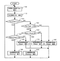
本発明の第1の実施の形態における冷凍サイクル装置の制御方法を、図1に概略構成図を示す冷凍サイクル装置を用いて説明する。図1の冷凍サイクル装置は、電動機1により駆動される圧縮機構2、利用側熱交換器としての放熱器3の冷媒流路、発電機4により動力回収される膨張機構5、熱源側熱交換器としての蒸発器6などからなり、冷媒として例えばCO2冷媒が封入されている冷媒回路Aと、利用流体搬送手段としての給水ポンプ7、放熱器3の流体流路、および給湯タンク8などからなる流体回路Bとから構成されている。
(Embodiment 1)
A control method for the refrigeration cycle apparatus according to the first embodiment of the present invention will be described with reference to the refrigeration cycle apparatus schematically shown in FIG. The refrigeration cycle apparatus of FIG. 1 includes a
さらに、この冷凍サイクル装置は熱源流体搬送手段としての送風装置9を備えており、送風装置9は、蒸発器6に熱源流体(例えば、外気)を送風する。また、電動機1の回転数を制御する圧縮機構制御手段10、発電機4の回転数を制御する膨張機構制御手段11を備えている。膨張機構制御手段11により、冷凍サイクルの状態に応じて膨張機構5の回転数を適切に変更し、例えば、高圧側圧力、吐出温度などを変更することができる。
Further, the refrigeration cycle apparatus includes a blower 9 as a heat source fluid transport unit, and the blower 9 blows a heat source fluid (for example, outside air) to the
さらに、吐出温度検知手段12は、圧縮機構2の吐出側から放熱器3の冷媒入口側までの冷媒配管上に備えられており、圧縮機構2の吐出温度を検知する。熱源流体入口温度検知手段としての外気温度検知手段13は、蒸発器6のフィン等に固定されており、蒸発器6に流入する外気の温度を検知する。利用流体温度検知手段としての入水温度検知手段14は、給湯タンク8の底部から放熱器6の流体入口側までの流体配管上に備えられており、放熱器6に流入する利用流体(例えば、水)の温度を検知する。電子制御手段15は、吐出温度検知手段12、外気温度検知手段13、入水温度検知手段14などからの信号により、冷凍サイクルの状態を判断し、圧縮機構制御手段10、膨張機構制御手段11などに指示を与える。
Further, the discharge temperature detection means 12 is provided on the refrigerant pipe from the discharge side of the
次に、上述のように構成された冷凍サイクル装置の動作で、特に、外気温度や入水温度の変化が少ない、あるいは、利用者からの指示がないなど、冷凍サイクルの変化が小さい場合の動作について説明する。冷媒回路Aでは、CO2冷媒を、圧縮機構2で臨界圧力を越える圧力まで圧縮する。その圧縮された冷媒は、高温高圧状態となり、放熱器3の冷媒流路を流れる際に、放熱器3の流体流路を流れる水に放熱し冷却される。その後、冷媒は膨張機構5で減圧され低温低圧の気液二相状態となる。膨張機構5で回収された膨張時の圧力エネルギーは、発電機4に伝達され、電力として回収される。
Next, regarding the operation of the refrigeration cycle apparatus configured as described above, particularly when the change in the refrigeration cycle is small, such as a small change in the outside air temperature or the incoming water temperature, or no instruction from the user. explain. In the refrigerant circuit A, the CO 2 refrigerant is compressed by the
すなわち、膨張時の圧力エネルギーを動力として回収しCOPを向上させることができる。膨張機構5で減圧された冷媒は蒸発器6に供給される。蒸発器6では、冷媒は送風装置9によって送り込まれた外気によって加熱され、気液二相またはガス状態となる。蒸発器6を流出した冷媒は、再び、圧縮機構2に吸入される。一方、流体回路Bでは、給湯タンク8の底部から給水ポンプ7により放熱器3の流体流路へ送り込まれた利用流体(例えば、水)は、放熱器3の冷媒流路を流れる冷媒により加熱され、高温の流体(例えば、お湯)となり、その高温流体を給湯タンク8の頂部から貯める。このようなサイクルを繰り返すことにより、本実施例の冷凍サイクル装置は、給湯機として利用できる。
That is, COP can be improved by recovering pressure energy during expansion as power. The refrigerant decompressed by the expansion mechanism 5 is supplied to the
次に、制御方法について説明する。圧縮機構2、実質的には駆動源である電動機1は、外気温度検知手段13、入水温度検知手段14などが検知した外気温度や入水温度、利用者等が設定した目標沸上温度(給湯タンクに貯めるお湯の温度、または、放熱器6の流体出口側温度の目標値)などから電子制御装置15が算出した回転数(以降、第1目標圧縮機構回転数と呼ぶ)となるように、圧縮機構制御手段10により制御されている。
Next, a control method will be described. The
また、膨張機構5、実質的には発電機4は、図2に示すフローチャートのように、膨張機構制御手段11により制御されている。電子制御装置15は、外気温度検知手段13、入水温度検知手段14などが検知した外気温度や入水温度、利用者等が設定した沸上温度(給湯タンクに貯めるお湯の温度、または、放熱器6の流体出口側温度)などから、冷凍サイクルの状態が最適となる目標吐出温度Td0を算出する(ステップ100)。
Further, the expansion mechanism 5, substantially the
この目標吐出温度Td0は、圧縮機構2などの構成要素の使用温度上限や圧力上限を越えないように設定されている。次に、吐出温度検知手段12により吐出温度Tdを検知する(ステップ110)。検知した吐出温度Tdが目標吐出温度Td0にある一定値ΔT1を加えた値より、大きいか否かを判定する(ステップ120)。なお、ΔT1は、冷凍サイクルの状態の安定性を増すために、吐出温度Tdがある一定の温度範囲となるように加える微少値である。
This target discharge temperature Td0 is set so as not to exceed the use temperature upper limit and pressure upper limit of components such as the
ステップ120において、吐出温度TdがTd0+ΔT1より高いと判定された場合には、ステップ130で、膨張機構5の回転数Rexpが、膨張機構5の使用上限回転数Rexp_maxより、大きいか否かを判定する。膨張機構5の使用上限回転数Rexp_maxは、膨張機構5や膨張機構制御手段11の保護するための上限値として設定されている。ステップ130において、膨張機構5の回転数Rexpが、使用上限回転数Rexp_maxより小さいと判定された場合には、膨張機構5、および、発電機4の回転数をある一定量、増加させるように膨張機構制御手段11に指示する(ステップ140)。これにより、膨張機構5を流通する冷媒量が増加するため、吐出温度Tdや高圧側圧力を低下させることができる。
If it is determined in
ステップ120において、吐出温度TdがTd0+ΔT1より低いと判定された場合には、ステップ150で、吐出温度Tdが目標吐出温度Td0よりある一定値ΔT2を減じた値より、小さいか否かを判定する。なお、ΔT2は、冷凍サイクルの状態の安定性を増すために、吐出温度Tdがある一定の温度範囲となるように減じる微少値である。ステップ150において、吐出温度TdがTd0−ΔT2より低いと判定された場合には、ステップ160で、膨張機構5の回転数Rexpが、膨張機構5の使用下限回転数Rexp_minより、小さいか否かを判定する。
If it is determined in
膨張機構5の使用下限回転数Rexp_minは、膨張機構5や膨張機構制御手段11の保護するための下限値として設定されている。ステップ160において、膨張機構5の回転数Rexpが、使用下限回転数Rexp_minより大きいと判定された場合には、膨張機構5、および、発電機4の回転数をある一定量、低下させるように膨張機構制御手段11に指示する(ステップ170)。これにより、膨張機構5を流通する冷媒量が低下するため、吐出温度Tdや高圧側圧力を上昇させることができる。
The lower limit rotation speed Reexp_min of the expansion mechanism 5 is set as a lower limit value for protecting the expansion mechanism 5 and the expansion mechanism control means 11. If it is determined in
ステップ120において、吐出温度TdがTd0+ΔT1より低いと判定され、ステップ150において、吐出温度TdがTd0−ΔT2より高いと判定された場合には、吐出温度は目標吐出温度Td0に近い、ある一定の温度範囲に入っているので、現在の膨張機構5、および、発電機4の回転数を維持するように膨張機構制御手段11に指示する(ステップ180)。
If it is determined in
一方、ステップ120において、吐出温度TdがTd0+ΔT1より高いと判定され、ステップ130において、膨張機構5の回転数Rexpが、使用上限回転数Rexp_maxより大きいと判定された場合には、これ以上、膨張機構5の回転数を増加させると信頼性の低下を招く恐れがあるため、圧縮機構2、および、電動機1の回転数をある一定量、低下させるように圧縮機構制御手段10に指示する(ステップ190)。これにより、膨張機構5の使用上限回転数Rexp_maxを越えることなく、吐出温度Tdや高圧側圧力を低下させることができる。
On the other hand, if it is determined in
ステップ120において、吐出温度TdがTd0+ΔT1より低いと判定され、ステップ150において、吐出温度TdがTd0−ΔT2より低いと判定され、ステップ160において、膨張機構5の回転数Rexpが、使用下限回転数Rexp_minより小さいと判定された場合には、これ以上、膨張機構5の回転数を低下させると信頼性の低下を招く恐れがあるため、圧縮機構2、および、電動機1の回転数をある一定量、増加させるように圧縮機構制御手段10に指示する(ステップ200)。これにより、膨張機構5の使用下限回転数Rexp_minを越えることなく、吐出温度Tdや高圧側圧力を上昇させることができる。
In
以上のステップ120から180の動作によれば、吐出温度Tdが目標吐出温度の上限値(Td0+ΔT1)を越える場合には、膨張機構5、および、発電機4の回転数を増加させるように変更し、吐出温度Tdを下げるようにするので、冷凍サイクル装置を保護するために圧縮機構2などの運転を停止する必要が無くなり、安定的に冷凍サイクル装置を運転することができる。また、吐出温度Tdが目標吐出温度の下限値(Td0−ΔT2)を下回る場合には、膨張機構5、および、発電機4の回転数を低下させるように変更し、吐出温度Tdを上げるようにするので、不必要に吐出温度Tdを下げることなく、安定的に冷凍サイクル装置を運転することができる。なお、以上のステップ120から180の動作によって、決定された膨張機構5の目標膨張機構回転数をこれ以降、第1目標膨張機構回転数と呼ぶ。
According to the operations from
さらに、ステップ190から200の動作によれば、吐出温度Tdが目標吐出温度の上限値(Td0+ΔT1)を越える場合で、膨張機構5の回転数Rexpが、使用上限回転数Rexp_maxより大きい場合には、膨張機構5、および、発電機4の回転数を増加させ、吐出温度Tdを下げるかわりに、圧縮機構2、および、電動機1の回転数を減少させ、吐出温度Tdを下げるようにするので、膨張機構5などを保護するために圧縮機構2などの運転を停止する必要が無くなり、安定的に冷凍サイクル装置を運転することができる。
Further, according to the operations of
また、吐出温度Tdが目標吐出温度の下限値(Td0−ΔT2)を下回る場合で、膨張機構5の回転数Rexpが、使用下限回転数Rexp_minより小さい場合には、膨張機構5、および、発電機4の回転数を低下させ、吐出温度Tdを上げるかわりに、圧縮機構2、および、電動機1の回転数を増加させ、吐出温度Tdを上げるようにするので、膨張機構5などを保護するために圧縮機構2などの運転を停止する必要が無くなり、安定的に冷凍サイクル装置を運転することができる。
Further, when the discharge temperature Td is lower than the lower limit value (Td0−ΔT2) of the target discharge temperature and the rotation speed Reexp of the expansion mechanism 5 is smaller than the use lower limit rotation speed Reexp_min, the expansion mechanism 5 and the generator In order to protect the expansion mechanism 5 and the like, the rotation speed of the
なお、上述のステップ190から200の動作を省略しても、ステップ120から180の動作による効果を得られることは明らかである。また、ステップ190、ステップ200のいずれか一方の動作を省略しても、省略しないステップの動作による効果が得られることは明らかである。
Obviously, even if the operations in
また、ΔT1、ΔT2は同じ値としてもよいし、異なる値としてもよい。さらに、ΔT1、ΔT2のいずれか一方、あるいは、両方を0としてもよい。 ΔT1 and ΔT2 may be the same value or different values. Furthermore, one or both of ΔT1 and ΔT2 may be set to zero.
(実施の形態2)
本発明の第2の実施の形態における冷凍サイクル装置の起動時の制御方法を、図3に示すタイムチャート、図4に示す膨張機構5の制御のフローチャート、図5に示す圧縮機構2の制御のフローチャートを用いて説明する。なお、冷凍サイクル装置の概略構成は図1と同様であるため、説明を省略する。
(Embodiment 2)
The control method at the time of starting of the refrigeration cycle apparatus in the second embodiment of the present invention, the time chart shown in FIG. 3, the flowchart of the control of the expansion mechanism 5 shown in FIG. 4, the control of the
利用者からの指示や、予め定められた運転時刻になると、電子制御装置15により冷凍サイクル装置の起動が行われる。本実施の形態では、圧縮機構2を起動させる前に膨張機構5を起動させる。膨張機構5、実質的には発電機4は、図4に示すフローチャートのように、膨張機構制御手段11により制御される。電子制御装置15は、外気温度検知手段13により外気温度を検知し(ステップ300)、入水温度検知手段14により入水温度を検知する(ステップ310)。検知した外気温度や入水温度などから冷凍サイクル装置の起動時における膨張機構5の回転数である第2目標膨張機構回転数を算出する(ステップ320)。この第2目標膨張機構回転数は、起動時において圧縮機構2や膨張機構5などの構成要素の使用温度上限や圧力上限を越えないように、外気温度が高いほど回転数が高く、入水温度が高いほど回転数が高くなるように、かつ、第1の実施の形態で説明した第1目標膨張機構回転数より小さい値が設定されている。
When an instruction from the user or a predetermined operation time is reached, the
次に、第2目標膨張機構回転数で膨張機構5を運転(起動)する(ステップ330)。さらに、膨張機構5の起動後、所定時間Te1経過したかを判定する(ステップ340)。所定時間Te1経過していない場合には、ステップ330に戻り、第2目標膨張機構回転数での運転を継続する。一方、所定時間Te1経過した場合には、第1の実施の形態で説明した図2のフローチャートのステップ100〜200へと進み、第1目標膨張機構回転数で運転する。
Next, the expansion mechanism 5 is operated (activated) at the second target expansion mechanism rotation speed (step 330). Further, it is determined whether a predetermined time Te1 has elapsed after the expansion mechanism 5 is activated (step 340). If the predetermined time Te1 has not elapsed, the process returns to step 330, and the operation at the second target expansion mechanism rotational speed is continued. On the other hand, when the predetermined time Te1 has elapsed, the process proceeds to
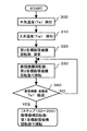
一方、圧縮機構2、実質的には駆動源である電動機1は、図5に示すフローチャートのように、圧縮機構制御手段10により制御される。電子制御装置15は、外気温度検知手段13により外気温度を検知し(ステップ400)、入水温度検知手段14により入水温度を検知する(ステップ410)。検知した外気温度や入水温度などから冷凍サイクル装置の起動時における圧縮機構2の回転数である第2目標圧縮機構回転数を算出する(ステップ420)。この第2目標圧縮機構回転数は、起動時において圧縮機構2や膨張機構5などの構成要素の使用温度上限や圧力上限を越えないように、かつ、第1の実施の形態で説明した第1目標圧縮機構回転数より小さい値が設定されている。
On the other hand, the
これにより、起動時に圧縮機構2を停止状態から急激に回転数を増加させた場合に生じる恐れのある潤滑油が不足するなどの信頼性低下を防止できる。次に、膨張機構5が起動してから、所定時間T0経過したかを判定する(ステップ430)。所定時間T0経過していない場合には、ステップ400に戻り、外気温度、入水温度の検知を更新し、第2目標圧縮機構回転数の算出を更新する。所定時間T0経過した場合には、第2目標圧縮機構回転数で圧縮機構2を運転(起動)する(ステップ440)。
Thereby, it is possible to prevent a decrease in reliability such as lack of lubricating oil that may occur when the rotation speed of the
次に、圧縮機構2の起動後、所定時間Tc1経過したかを判定する(ステップ450)。所定時間Tc1経過していない場合には、ステップ440に戻り、第2目標圧縮機構回転数での運転を継続する。一方、所定時間Tc1経過した場合には、再び外気温度検知手段13により外気温度を検知し(ステップ460)、入水温度検知手段14により入水温度を検知する(ステップ470)。検知した外気温度や入水温度などから冷凍サイクル装置の安定時における圧縮機構2の回転数である第1目標圧縮機構回転数を算出する(ステップ480)。
Next, it is determined whether a predetermined time Tc1 has elapsed after the
この第1目標圧縮機構回転数は、冷凍サイクルが比較的安定した場合に、必要な加熱量が確保できるように設定されている。また、所定時間Tc1は(所定時間Te1−所定時間T0)より大きい値が設定されている。次に、圧縮機構2の回転数を第1目標圧縮機構回転数に変更し運転する(ステップ490)。その後、ステップ460に戻り、外気温度、入水温度の検知の更新、第1目標圧縮機構回転数の算出の更新を、定められた制御周期で繰り返し、他の指示、例えば、冷凍サイクル装置の停止指示まで、第1目標圧縮機構回転数での運転を継続する。
The first target compression mechanism rotational speed is set so that a necessary heating amount can be secured when the refrigeration cycle is relatively stable. The predetermined time Tc1 is set to a value greater than (predetermined time Te1-predetermined time T0). Next, the rotation speed of the
以上の動作によれば、図2に示すタイムチャートのように、膨張機構5が外気温度、入水温度から算出された第2目標膨張機構回転数で起動した後、所定時間T0経過後、圧縮機構2が外気温度、入水温度から算出された第2目標圧縮機構回転数で起動する。このため、圧縮機構2の起動の際に、膨張機構5が停止しているために急激に高圧側圧力が上昇するなどの不具合が生じることなく、安定した冷凍サイクル装置の起動が実現できる。また、第2目標膨張機構回転数は外気温度、入水温度に応じて、高圧側圧力が上昇しやすい状態ほど、回転数が大きくなるように設定されているので、さらに、急激な高圧側圧力の上昇を防止でき、安定した冷凍サイクル装置の起動が実現できる。
According to the above operation, as shown in the time chart of FIG. 2, after the expansion mechanism 5 is started at the second target expansion mechanism rotational speed calculated from the outside air temperature and the incoming water temperature, after the predetermined time T0 has elapsed, the
また、圧縮機構2の起動後、所定時間Tc1経過すると、圧縮機構2の回転数は、外気温度、入水温度から算出された第1目標圧縮機構回転数に増加するが、膨張機構5の起動後、所定時間Te1経過した時点で、膨張機構5の回転数は、第1の実施の形態で説明した第1目標膨張機構回転数へと予め増加する。このように、圧縮機構2の回転数が増加するより前に、膨張機構5の回転数が予め大きくなるように設定しているため、圧縮機構2の回転数が増加する際の急激な高圧側圧力の上昇を防止でき、安定した冷凍サイクル装置の起動が実現できる。
When the predetermined time Tc1 elapses after the
なお、本実施の形態では、圧縮機構2の回転数を増加させる前に、膨張機構5の回転数を増加させるものとして説明したが、圧縮機構2の回転数を増加させると同時に、膨張機構5の回転数を増加させる(すなわち、T0を0とする)場合でも同様の効果が得られる。
In the present embodiment, it has been described that the rotation speed of the expansion mechanism 5 is increased before the rotation speed of the
また、本実施の形態では、第1目標膨張機構回転数、第2目標膨張機構回転数などは、外気温度と入水温度とに応じて決定するものとしているが、いずれか一方の温度に応じて決定するものとしてもよい。 Further, in the present embodiment, the first target expansion mechanism rotation speed, the second target expansion mechanism rotation speed, and the like are determined according to the outside air temperature and the incoming water temperature, but according to any one of the temperatures. It may be determined.
また、本実施の形態では、冷凍サイクルの変化が小さい場合での圧縮機構2の目標回転数である第1目標圧縮機構回転数、および、膨張機構5の目標回転数である第1目標膨張機構回転数に到達する以前に、それらより小さい回転数に設定された第2目標圧縮機構回転数、および、第2目標圧縮機構回転数を設けているが、第1目標圧縮機構回転数、および、第1目標膨張機構回転数に到達する以前の区間を、複数の区間に分けて、段階的に目標圧縮機構回転数、および、目標膨張機回転数を変化させるように、複数の第2目標圧縮機構回転数、および、第2目標膨張機構回転数を設けてもよい。
In the present embodiment, the first target compression mechanism rotation speed that is the target rotation speed of the
(実施の形態3)
本発明の第3の実施の形態における冷凍サイクル装置の起動時の制御方法を、図6に示すタイムチャート、図7に示す膨張機構5の制御のフローチャートを用いて説明する。なお、冷凍サイクル装置の概略構成は図1と同様であるため、説明を省略する。また、圧縮機構2の制御方法は第2の実施の形態と同様であるため、説明を省略する。
(Embodiment 3)
A control method at the time of starting the refrigeration cycle apparatus according to the third embodiment of the present invention will be described with reference to a time chart shown in FIG. 6 and a flowchart of control of the expansion mechanism 5 shown in FIG. The schematic configuration of the refrigeration cycle apparatus is the same as that shown in FIG. Moreover, since the control method of the
利用者からの指示や、予め定められた運転時刻になると、電子制御装置15により冷凍サイクル装置の起動が行われる。本実施の形態では、圧縮機構2を起動させる前に膨張機構5を起動させる。膨張機構5、実質的には発電機4は、図7に示すフローチャートのように、膨張機構制御手段11により制御される。電子制御装置15は、外気温度検知手段13により外気温度を検知し(ステップ500)、入水温度検知手段14により入水温度を検知する(ステップ510)。検知した外気温度や入水温度などから冷凍サイクル装置の起動時における膨張機構5の回転数である第2目標膨張機構回転数を算出する(ステップ520)。この第2目標膨張機構回転数は、起動時において圧縮機構2や膨張機構5などの構成要素の使用温度上限や圧力上限を越えないように、外気温度が高いほど回転数が高く、入水温度が高いほど回転数が高くなるように、かつ、第1の実施の形態で説明した第1目標膨張機構回転数より小さい値が設定されている。
When an instruction from the user or a predetermined operation time is reached, the
次に、第2目標膨張機構回転数で膨張機構5を運転(起動)する(ステップ530)。さらに、膨張機構5の起動後、所定時間Te2経過したかを判定する(ステップ540)。所定時間Te2経過していない場合には、ステップ530に戻り、第2目標膨張機構回転数での運転を継続する。一方、所定時間Te2経過した場合には、外気温度検知手段13により外気温度の検知を更新し(ステップ550)、入水温度検知手段14により入水温度の検知を更新する(ステップ560)。 Next, the expansion mechanism 5 is operated (activated) at the second target expansion mechanism rotation speed (step 530). Further, it is determined whether a predetermined time Te2 has elapsed after the expansion mechanism 5 is started (step 540). If the predetermined time Te2 has not elapsed, the process returns to step 530, and the operation at the second target expansion mechanism rotational speed is continued. On the other hand, when the predetermined time Te2 has elapsed, the detection of the outside air temperature is updated by the outside air temperature detecting means 13 (step 550), and the detection of the incoming water temperature is updated by the incoming water temperature detecting means 14 (step 560).
検知した外気温度や入水温度などから冷凍サイクル装置の起動時における膨張機構5の回転数である第3目標膨張機構回転数を算出する(ステップ570)。この第3目標膨張機構回転数は、起動時において圧縮機構2や膨張機構5などの構成要素の使用温度上限や圧力上限を越えないように、外気温度が高いほど回転数が高く、入水温度が高いほど回転数が高くなるように、かつ、第1の実施の形態で説明した第1目標膨張機構回転数より大きい値に設定されている。
A third target expansion mechanism rotational speed that is the rotational speed of the expansion mechanism 5 at the time of starting the refrigeration cycle apparatus is calculated from the detected outside air temperature, incoming water temperature, and the like (step 570). The third target expansion mechanism rotational speed is such that the higher the outside air temperature is, the higher the rotational speed is, and the incoming water temperature is such that the operating temperature upper limit and pressure upper limit of the components such as the
次に、第3目標膨張機構回転数で膨張機構5を運転する(ステップ580)。さらに、膨張機構5の起動後、所定時間Te3経過したかを判定する(ステップ590)。所定時間Te3経過していない場合には、ステップ550に戻り、再び、外気温度や入水温度の検知の更新と第3目標膨張機構回転数の演算を行った後、第3目標膨張機構回転数での運転を継続する。一方、所定時間Te3経過した場合には、第1の実施の形態で説明した図2のフローチャートのステップ100〜200へと進み、第1目標膨張機構回転数で運転する。
Next, the expansion mechanism 5 is operated at the third target expansion mechanism rotation speed (step 580). Further, it is determined whether a predetermined time Te3 has elapsed after the expansion mechanism 5 is activated (step 590). If the predetermined time Te3 has not elapsed, the process returns to step 550, and after updating the detection of the outside air temperature and the incoming water temperature and calculating the third target expansion mechanism rotational speed again, the third target expansion mechanism rotational speed is reached. Continue driving. On the other hand, when the predetermined time Te3 has elapsed, the process proceeds to
以上の動作によれば、図6に示すタイムチャートのように、膨張機構5が外気温度、入水温度から算出された第2目標膨張機構回転数で起動した後、所定時間Te3経過すると、膨張機構5の回転数は、第1の実施の形態で説明した第1目標膨張機構回転数へと増加する。しかし、所定時間Te3経過する以前の所定時間Te2経過した時点で、膨張機構5の回転数は、第2目標膨張機構回転数より大きい値に設定された第3目標膨張機構回転数で運転されるので、膨張機構5の回転数が、第2目標膨張機構回転数から第1目標膨張機構回転数へと増加する際の急激な高圧側圧力の変化を防止でき、起動時間を短縮しつつ安定した冷凍サイクル装置の起動が実現できる。 According to the above operation, as shown in the time chart of FIG. 6, when the expansion mechanism 5 is started at the second target expansion mechanism rotation speed calculated from the outside air temperature and the incoming water temperature, when the predetermined time Te3 has elapsed, the expansion mechanism 5 The rotational speed of 5 increases to the first target expansion mechanism rotational speed described in the first embodiment. However, when the predetermined time Te2 elapses before the predetermined time Te3 elapses, the rotation speed of the expansion mechanism 5 is operated at the third target expansion mechanism rotation speed set to a value larger than the second target expansion mechanism rotation speed. Therefore, it is possible to prevent a rapid change in the high-pressure side pressure when the rotation speed of the expansion mechanism 5 increases from the second target expansion mechanism rotation speed to the first target expansion mechanism rotation speed, and to stabilize the startup time. Activation of the refrigeration cycle apparatus can be realized.
また、本実施の形態では、第3目標膨張機構回転数は、外気温度と入水温度とに応じて決定するものとしているが、いずれか一方の温度に応じて決定するものとしてもよい。 In the present embodiment, the third target expansion mechanism rotational speed is determined according to the outside air temperature and the incoming water temperature, but may be determined according to any one of the temperatures.
(実施の形態4)
本発明の第4の実施の形態における冷凍サイクル装置の起動時の制御方法を、図8に示す膨張機構5の制御のフローチャートを用いて説明する。図8において、図7と同じ制御ステップについては、同一の番号を付し、説明を省略する。また、冷凍サイクル装置の概略構成は図1と同様であるため、説明を省略する。さらに、圧縮機構2の制御方法は第2の実施の形態と同様であるため、説明を省略する。
(Embodiment 4)
A control method at the start of the refrigeration cycle apparatus according to the fourth embodiment of the present invention will be described with reference to a control flowchart of the expansion mechanism 5 shown in FIG. 8, the same control steps as those in FIG. 7 are denoted by the same reference numerals, and description thereof is omitted. The schematic configuration of the refrigeration cycle apparatus is the same as that shown in FIG. Furthermore, since the control method of the
ステップ580において第3目標膨張機構回転数で膨張機構5を運転し、さらに、膨張機構5の起動後、所定時間Te3経過したかを判定する(ステップ590)。所定時間Te3経過していない場合には、吐出温度検知手段12により吐出温度Tdを検知する(ステップ600)。目標吐出温度Td0と検知した吐出温度Tdの差がある一定値ΔT3より小さいか否かを判定する(ステップ610)。なお、第1の実施の形態と同様に、目標吐出温度Td0は、外気温度や入水温度、利用者等が設定した目標沸上温度(給湯タンクに貯めるお湯の温度、または、放熱器6の流体出口側温度の目標値)などから、冷凍サイクルの状態が最適となるように設定されており、ΔT3は、吐出温度Tdが目標吐出温度Td0に近づいたことを判定するための微少値である。
In
ステップ610において、目標吐出温度Td0と検知した吐出温度Tdの差がある一定値ΔT3より大きいと判定された場合には、吐出温度Tdは目標吐出温度Td0に十分に近づいていないので、ステップ550に戻り、再び、外気温度や入水温度の検知の更新と第3目標膨張機構回転数の演算を行った後、第3目標膨張機構回転数での運転を継続する。一方、目標吐出温度Td0と検知した吐出温度Tdの差がある一定値ΔT3より小さいと判定された場合には、吐出温度Tdは目標吐出温度Td0に十分に近づいているので、第1の実施の形態で説明した図2のフローチャートのステップ100〜200へと進み、吐出温度を目標吐出温度に近づけるような膨張機構5の回転数である第1目標膨張機構回転数で運転する。
If it is determined in
また、ステップ590において、所定時間Te3経過したと判定された場合にも、第1の実施の形態で説明した図2のフローチャートのステップ100〜200へと進み、第1目標膨張機構回転数で運転する。
If it is determined in
以上の動作によれば、所定時間Te3を経過していなくても、吐出温度Tdが目標吐出温度Td0に近づいた場合には、所定時間Te3を経過した場合と同様に、次の目標膨張機構回転数に移行するものである。すなわち、吐出温度Tdが目標吐出温度Td0に近づいた場合には、所定時間Te3を経過したものとみなすものである。 According to the above operation, even if the predetermined time Te3 has not elapsed, when the discharge temperature Td approaches the target discharge temperature Td0, the next target expansion mechanism rotation is performed as in the case where the predetermined time Te3 has elapsed. The number will shift. That is, when the discharge temperature Td approaches the target discharge temperature Td0, it is considered that the predetermined time Te3 has elapsed.
このような動作によれば、所定時間Te3経過する以前であっても、吐出温度Tdが目標吐出温度Td0に近づいた場合には、膨張機構5の回転数は、第1目標膨張機構回転数に移行するので、不必要に第3目標膨張機構回転数で運転を行う時間を短縮でき、さらに起動時間を短縮しつつ安定した冷凍サイクル装置の起動が実現できる。 According to such an operation, even before the predetermined time Te3 has elapsed, when the discharge temperature Td approaches the target discharge temperature Td0, the rotation speed of the expansion mechanism 5 becomes the first target expansion mechanism rotation speed. Since the shift is made, it is possible to unnecessarily reduce the time for operation at the third target expansion mechanism rotation speed, and to realize stable start-up of the refrigeration cycle apparatus while reducing the start-up time.
なお、本実施の形態では、吐出温度Tdが目標吐出温度Td0に近づいた場合には、所定時間Te3を経過したものとみなすものとしたが、利用側熱交換器である放熱器3から流出する利用側流体出口温度(すなわち、沸上温度)が、予め定められた利用側流体出口温度の目標温度(すなわち、目標沸上温度)に近づけば、所定時間Te3を経過したものとみなすものとしてもよい。あるいは、吐出温度Tdが予め定められた目標沸上温度よりある一定温度差以上高くなれば、所定時間Te3を経過したものとみなすものとしてもよい。また、ΔT3は0としてもよい。 In the present embodiment, when the discharge temperature Td approaches the target discharge temperature Td0, it is assumed that the predetermined time Te3 has elapsed, but it flows out from the radiator 3 that is the use side heat exchanger. If the use side fluid outlet temperature (that is, the boiling temperature) approaches the target temperature (that is, the target boiling temperature) of the predetermined use side fluid outlet temperature, it may be considered that the predetermined time Te3 has elapsed. Good. Alternatively, if the discharge temperature Td is higher than a predetermined target boiling temperature by a certain temperature difference or more, it may be considered that the predetermined time Te3 has elapsed. ΔT3 may be 0.
さらに、第2から第3の実施の形態における所定時間Te1、Te2、Tc1などにおいても、吐出温度Tdが目標吐出温度Td0に近づいた場合や、沸上温度が目標沸上温度に近づいた場合や、吐出温度Tdが目標沸上温度よりある一定温度差以上高くなった場合にも、それぞれの所定時間を経過したとみなすようにしてもよい。 Further, also in the predetermined times Te1, Te2, Tc1, etc. in the second to third embodiments, when the discharge temperature Td approaches the target discharge temperature Td0, or when the boiling temperature approaches the target boiling temperature, Even when the discharge temperature Td becomes higher than the target boiling temperature by a certain temperature difference or more, it may be considered that each predetermined time has passed.
また、冷媒がCO2冷媒の場合には、高圧側圧力は凝縮温度に依存しない超臨界状態での圧力となるために、高圧側圧力が上昇しやすいが、以上の本実施の形態によれば、機器を保護するために圧縮機構の運転を停止することなく、安定した冷凍サイクル装置の運転が実現できる。 Further, when the refrigerant is a CO 2 refrigerant, the high pressure side pressure is a pressure in a supercritical state that does not depend on the condensation temperature, and thus the high pressure side pressure tends to increase. According to the above embodiment, Therefore, stable operation of the refrigeration cycle apparatus can be realized without stopping the operation of the compression mechanism to protect the equipment.
本発明の冷凍サイクル装置の制御方法およびそれを用いた冷凍サイクル装置は、膨張機構を備えた冷凍サイクル装置において、適切に膨張機構の回転数を制御し、冷凍サイクル装置を安定して運転させることが可能となるため、膨張機構を備えた給湯機、空気調和機などの用途に適用できる。 A control method for a refrigeration cycle apparatus according to the present invention and a refrigeration cycle apparatus using the same, in a refrigeration cycle apparatus provided with an expansion mechanism, appropriately control the number of revolutions of the expansion mechanism and allow the refrigeration cycle apparatus to operate stably. Therefore, it can be applied to uses such as a water heater and an air conditioner equipped with an expansion mechanism.
1 電動機
2 圧縮機構
3 利用側熱交換器(放熱器)
4 発電機
5 膨張機構
6 熱源側熱交換器(蒸発器)
7 利用流体搬送手段(給水ポンプ)
8 給湯タンク
9 熱源流体搬送手段(送風装置)
10 圧縮機構制御手段
11 膨張機構制御手段
12 吐出温度検知手段
13 外気温度検知手段
14 入水温度検知手段
15 電子制御手段15
A 冷媒回路
B 流体回路
DESCRIPTION OF
4 Generator 5
7 Fluid transport means (water supply pump)
8 Hot water tank 9 Heat source fluid transfer means (blower)
DESCRIPTION OF
A Refrigerant circuit B Fluid circuit
Claims (6)
Priority Applications (2)
| Application Number | Priority Date | Filing Date | Title |
|---|---|---|---|
| JP2005345487A JP4665736B2 (en) | 2005-11-30 | 2005-11-30 | Control method for refrigeration cycle apparatus and refrigeration cycle apparatus using the same |
| EP06024851A EP1793182A3 (en) | 2005-11-30 | 2006-11-30 | Control method of refrigeration cycle apparatus |
Applications Claiming Priority (1)
| Application Number | Priority Date | Filing Date | Title |
|---|---|---|---|
| JP2005345487A JP4665736B2 (en) | 2005-11-30 | 2005-11-30 | Control method for refrigeration cycle apparatus and refrigeration cycle apparatus using the same |
Publications (3)
| Publication Number | Publication Date |
|---|---|
| JP2007147211A JP2007147211A (en) | 2007-06-14 |
| JP2007147211A5 JP2007147211A5 (en) | 2008-10-23 |
| JP4665736B2 true JP4665736B2 (en) | 2011-04-06 |
Family
ID=37846204
Family Applications (1)
| Application Number | Title | Priority Date | Filing Date |
|---|---|---|---|
| JP2005345487A Expired - Fee Related JP4665736B2 (en) | 2005-11-30 | 2005-11-30 | Control method for refrigeration cycle apparatus and refrigeration cycle apparatus using the same |
Country Status (2)
| Country | Link |
|---|---|
| EP (1) | EP1793182A3 (en) |
| JP (1) | JP4665736B2 (en) |
Families Citing this family (5)
| Publication number | Priority date | Publication date | Assignee | Title |
|---|---|---|---|---|
| JP2011214779A (en) | 2010-03-31 | 2011-10-27 | Daikin Industries Ltd | Refrigerating device |
| JP2011237173A (en) * | 2011-08-29 | 2011-11-24 | Daikin Industries Ltd | Refrigerating device |
| JP5825041B2 (en) * | 2011-10-25 | 2015-12-02 | ダイキン工業株式会社 | Refrigeration equipment |
| JP2014119125A (en) * | 2012-12-13 | 2014-06-30 | Daikin Ind Ltd | Refrigeration device |
| ES2638600T3 (en) * | 2014-01-29 | 2017-10-23 | Fujitsu General Limited | Heat pump type device for heating and supplying hot water |
Citations (11)
| Publication number | Priority date | Publication date | Assignee | Title |
|---|---|---|---|---|
| JPS54100551A (en) * | 1978-01-24 | 1979-08-08 | Mitsubishi Heavy Ind Ltd | Refrigerator |
| JPS56112896A (en) * | 1980-02-12 | 1981-09-05 | Toshiba Corp | Freezing device |
| JPS5726362A (en) * | 1980-07-24 | 1982-02-12 | Matsushita Electric Ind Co Ltd | Air conditioner |
| JPS59191853A (en) * | 1983-04-15 | 1984-10-31 | 株式会社東芝 | Method of controlling refrigeration cycle |
| JPH04222341A (en) * | 1990-12-25 | 1992-08-12 | Daikin Ind Ltd | Operation controller for air conditioner |
| JPH0688647A (en) * | 1992-09-08 | 1994-03-29 | Daikin Ind Ltd | Operation controler for refrigeration device |
| JP2002106980A (en) * | 2000-09-29 | 2002-04-10 | Daikin Ind Ltd | Refrigerating device |
| JP2002122362A (en) * | 2000-10-13 | 2002-04-26 | Matsushita Electric Ind Co Ltd | Heat pump hot water supplier |
| JP2004108683A (en) * | 2002-09-19 | 2004-04-08 | Mitsubishi Electric Corp | Refrigeration air conditioner and operation method for refrigeration air conditioner |
| JP2004138332A (en) * | 2002-10-18 | 2004-05-13 | Matsushita Electric Ind Co Ltd | Refrigeration cycle device |
| WO2005103584A1 (en) * | 2004-04-27 | 2005-11-03 | Matsushita Electric Industrial Co., Ltd. | Heat pump device |
Family Cites Families (4)
| Publication number | Priority date | Publication date | Assignee | Title |
|---|---|---|---|---|
| US6272871B1 (en) * | 2000-03-30 | 2001-08-14 | Nissan Technical Center North America | Air conditioner with energy recovery device |
| JP2004061061A (en) * | 2002-07-31 | 2004-02-26 | Matsushita Electric Ind Co Ltd | Freezing cycle device and its operation method |
| US6898941B2 (en) * | 2003-06-16 | 2005-05-31 | Carrier Corporation | Supercritical pressure regulation of vapor compression system by regulation of expansion machine flowrate |
| JP3708536B1 (en) * | 2004-03-31 | 2005-10-19 | 松下電器産業株式会社 | Refrigeration cycle apparatus and control method thereof |
-
2005
- 2005-11-30 JP JP2005345487A patent/JP4665736B2/en not_active Expired - Fee Related
-
2006
- 2006-11-30 EP EP06024851A patent/EP1793182A3/en not_active Withdrawn
Patent Citations (11)
| Publication number | Priority date | Publication date | Assignee | Title |
|---|---|---|---|---|
| JPS54100551A (en) * | 1978-01-24 | 1979-08-08 | Mitsubishi Heavy Ind Ltd | Refrigerator |
| JPS56112896A (en) * | 1980-02-12 | 1981-09-05 | Toshiba Corp | Freezing device |
| JPS5726362A (en) * | 1980-07-24 | 1982-02-12 | Matsushita Electric Ind Co Ltd | Air conditioner |
| JPS59191853A (en) * | 1983-04-15 | 1984-10-31 | 株式会社東芝 | Method of controlling refrigeration cycle |
| JPH04222341A (en) * | 1990-12-25 | 1992-08-12 | Daikin Ind Ltd | Operation controller for air conditioner |
| JPH0688647A (en) * | 1992-09-08 | 1994-03-29 | Daikin Ind Ltd | Operation controler for refrigeration device |
| JP2002106980A (en) * | 2000-09-29 | 2002-04-10 | Daikin Ind Ltd | Refrigerating device |
| JP2002122362A (en) * | 2000-10-13 | 2002-04-26 | Matsushita Electric Ind Co Ltd | Heat pump hot water supplier |
| JP2004108683A (en) * | 2002-09-19 | 2004-04-08 | Mitsubishi Electric Corp | Refrigeration air conditioner and operation method for refrigeration air conditioner |
| JP2004138332A (en) * | 2002-10-18 | 2004-05-13 | Matsushita Electric Ind Co Ltd | Refrigeration cycle device |
| WO2005103584A1 (en) * | 2004-04-27 | 2005-11-03 | Matsushita Electric Industrial Co., Ltd. | Heat pump device |
Also Published As
| Publication number | Publication date |
|---|---|
| JP2007147211A (en) | 2007-06-14 |
| EP1793182A2 (en) | 2007-06-06 |
| EP1793182A3 (en) | 2011-05-18 |
Similar Documents
| Publication | Publication Date | Title |
|---|---|---|
| JP5121844B2 (en) | Refrigeration cycle equipment | |
| JP4912308B2 (en) | Refrigeration cycle equipment | |
| JP4053082B2 (en) | Refrigeration cycle equipment | |
| JP5040256B2 (en) | Refrigeration cycle apparatus and control method thereof | |
| JP2006132818A (en) | Control method for refrigerating cycle device, and refrigerating cycle device using the same | |
| JP2005291622A (en) | Refrigerating cycle device and its control method | |
| JP2006517643A (en) | Supercritical pressure regulation of vapor compression system | |
| JP4317793B2 (en) | Cooling system | |
| JP4665736B2 (en) | Control method for refrigeration cycle apparatus and refrigeration cycle apparatus using the same | |
| JP2007147211A5 (en) | ||
| WO2006112157A1 (en) | Refrigeration cycle device and method of operating the same | |
| JP2011085284A (en) | Heat pump type heating device | |
| JP2009085463A (en) | Air conditioner | |
| JP2005325746A (en) | Exhaust heat recovery system for vehicle | |
| JP5381749B2 (en) | Refrigeration cycle equipment | |
| JP4075844B2 (en) | Heat pump water heater | |
| JP2006194537A (en) | Heat pump device | |
| JP2006132888A (en) | Heat pump hot water supply apparatus | |
| JP6150906B2 (en) | Refrigeration cycle equipment | |
| JP2007187332A (en) | Refrigeration cycle device | |
| JP2005188923A (en) | Heat pump water heater | |
| JP2010038463A (en) | Refrigerating cycle device | |
| JP2007010257A (en) | Heat pump device | |
| JP6150907B2 (en) | Refrigeration cycle equipment | |
| JP4251136B2 (en) | Heat pump water heater |
Legal Events
| Date | Code | Title | Description |
|---|---|---|---|
| A521 | Written amendment |
Free format text: JAPANESE INTERMEDIATE CODE: A523 Effective date: 20080905 |
|
| A621 | Written request for application examination |
Free format text: JAPANESE INTERMEDIATE CODE: A621 Effective date: 20080905 |
|
| RD01 | Notification of change of attorney |
Free format text: JAPANESE INTERMEDIATE CODE: A7421 Effective date: 20091127 |
|
| A977 | Report on retrieval |
Free format text: JAPANESE INTERMEDIATE CODE: A971007 Effective date: 20100408 |
|
| A131 | Notification of reasons for refusal |
Free format text: JAPANESE INTERMEDIATE CODE: A131 Effective date: 20100518 |
|
| A521 | Written amendment |
Free format text: JAPANESE INTERMEDIATE CODE: A523 Effective date: 20100607 |
|
| TRDD | Decision of grant or rejection written | ||
| A01 | Written decision to grant a patent or to grant a registration (utility model) |
Free format text: JAPANESE INTERMEDIATE CODE: A01 Effective date: 20101214 |
|
| A01 | Written decision to grant a patent or to grant a registration (utility model) |
Free format text: JAPANESE INTERMEDIATE CODE: A01 |
|
| A61 | First payment of annual fees (during grant procedure) |
Free format text: JAPANESE INTERMEDIATE CODE: A61 Effective date: 20101227 |
|
| FPAY | Renewal fee payment (event date is renewal date of database) |
Free format text: PAYMENT UNTIL: 20140121 Year of fee payment: 3 |
|
| FPAY | Renewal fee payment (event date is renewal date of database) |
Free format text: PAYMENT UNTIL: 20140121 Year of fee payment: 3 |
|
| LAPS | Cancellation because of no payment of annual fees |