EP3556519B1 - Verfahren zur korrektur der zielposition eines arbeitsroboters - Google Patents
Verfahren zur korrektur der zielposition eines arbeitsroboters Download PDFInfo
- Publication number
- EP3556519B1 EP3556519B1 EP16924068.6A EP16924068A EP3556519B1 EP 3556519 B1 EP3556519 B1 EP 3556519B1 EP 16924068 A EP16924068 A EP 16924068A EP 3556519 B1 EP3556519 B1 EP 3556519B1
- Authority
- EP
- European Patent Office
- Prior art keywords
- block
- target position
- blocks
- amount
- work robot
- Prior art date
- Legal status (The legal status is an assumption and is not a legal conclusion. Google has not performed a legal analysis and makes no representation as to the accuracy of the status listed.)
- Active
Links
Images


Classifications
-
- B—PERFORMING OPERATIONS; TRANSPORTING
- B25—HAND TOOLS; PORTABLE POWER-DRIVEN TOOLS; MANIPULATORS
- B25J—MANIPULATORS; CHAMBERS PROVIDED WITH MANIPULATION DEVICES
- B25J9/00—Program-controlled manipulators
- B25J9/16—Program controls
- B25J9/1628—Program controls characterised by the control loop
- B25J9/163—Program controls characterised by the control loop learning, adaptive, model based, rule based expert control
-
- B—PERFORMING OPERATIONS; TRANSPORTING
- B25—HAND TOOLS; PORTABLE POWER-DRIVEN TOOLS; MANIPULATORS
- B25J—MANIPULATORS; CHAMBERS PROVIDED WITH MANIPULATION DEVICES
- B25J9/00—Program-controlled manipulators
- B25J9/16—Program controls
- B25J9/1656—Program controls characterised by programming, planning systems for manipulators
- B25J9/1664—Program controls characterised by programming, planning systems for manipulators characterised by motion, path, trajectory planning
-
- B—PERFORMING OPERATIONS; TRANSPORTING
- B25—HAND TOOLS; PORTABLE POWER-DRIVEN TOOLS; MANIPULATORS
- B25J—MANIPULATORS; CHAMBERS PROVIDED WITH MANIPULATION DEVICES
- B25J9/00—Program-controlled manipulators
- B25J9/10—Program-controlled manipulators characterised by positioning means for manipulator elements
- B25J9/1005—Program-controlled manipulators characterised by positioning means for manipulator elements comprising adjusting means
-
- G—PHYSICS
- G05—CONTROLLING; REGULATING
- G05B—CONTROL OR REGULATING SYSTEMS IN GENERAL; FUNCTIONAL ELEMENTS OF SUCH SYSTEMS; MONITORING OR TESTING ARRANGEMENTS FOR SUCH SYSTEMS OR ELEMENTS
- G05B19/00—Program-control systems
- G05B19/02—Program-control systems electric
- G05B19/18—Numerical control [NC], i.e. automatically operating machines, in particular machine tools, e.g. in a manufacturing environment, so as to execute positioning, movement or co-ordinated operations by means of program data in numerical form
- G05B19/408—Numerical control [NC], i.e. automatically operating machines, in particular machine tools, e.g. in a manufacturing environment, so as to execute positioning, movement or co-ordinated operations by means of program data in numerical form characterised by data handling or data format, e.g. reading, buffering or conversion of data
- G05B19/4083—Adapting program, configuration
-
- G—PHYSICS
- G05—CONTROLLING; REGULATING
- G05B—CONTROL OR REGULATING SYSTEMS IN GENERAL; FUNCTIONAL ELEMENTS OF SUCH SYSTEMS; MONITORING OR TESTING ARRANGEMENTS FOR SUCH SYSTEMS OR ELEMENTS
- G05B2219/00—Program-control systems
- G05B2219/30—Nc systems
- G05B2219/36—Nc in input of data, input key till input tape
- G05B2219/36416—Adapt teached position as function of deviation 3-D, 2-D position of end effector, tool
-
- G—PHYSICS
- G05—CONTROLLING; REGULATING
- G05B—CONTROL OR REGULATING SYSTEMS IN GENERAL; FUNCTIONAL ELEMENTS OF SUCH SYSTEMS; MONITORING OR TESTING ARRANGEMENTS FOR SUCH SYSTEMS OR ELEMENTS
- G05B2219/00—Program-control systems
- G05B2219/30—Nc systems
- G05B2219/36—Nc in input of data, input key till input tape
- G05B2219/36504—Adapt program to real coordinates, shape, dimension of tool, offset path
Definitions
- the present description discloses a method for correcting a target position of a work robot.
- DH parameter are set as follows. That is, a control device of a robot divides an operation space for the robot into multiple regions and sets a measurement point for each of the divided regions. Next, the control device moves the robot to the measurement points to acquire three-dimensional position data. Then, the control device derives a DH parameter from an error between the acquired position data and the measurement point.
- the control device selects, in DH parameters derived individually for the multiple regions, a DH parameter of the region involving the target point and performs a coordinate transformation by applying the selected DH parameter to the target point.
- Patent Literature 1 JP-A-2009-148850
- a main object of the present disclosure is to position a work robot in a target position designated in an operation space of a three-dimensional matrix with good accuracy.
- the two blocks contiguous with the specific block including the target position are set as the first block and the second block. Then, the target position is corrected based on the respective reference points in the upper area and the lower area of the specific block and the measured deviation amount of the work robot from the reference points, the respective reference points in the upper area and the lower area of the first block and the measured deviation amount of the work robot from the reference points, and the respective reference points in the upper area and the lower area of the second block and the measured deviation amount of the work robot from the reference points. In this manner, the target position is corrected by making use of not only the measured deviation amount from the reference points of the specific block but also the measured deviation amount from the reference points of the two blocks that are contiguous with the specific block. Consequently, the work robot can be positioned in the target position designated in the operation space of the three-dimensional matrix with good accuracy.
- Fig. 1 is a block diagram illustrating a schematic configuration of robot system 10.
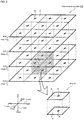
- Fig. 2 illustrates three-dimensional matrix 25.
- Fig. 3 is a block diagram illustrating an electrical connection relationship between robot 20 and control device 70.
- a left-right direction is referred to as an X-axis direction
- a front-rear direction is referred to as a Y-axis direction
- an up-down direction is referred to as a Z-axis direction.
- Robot system 10 includes robot 20 and control device 70 configured to control robot 20.
- Robot system 10 constitutes a system configured to pick up a workpiece and place the workpiece picked up on a target object.
- robot system 10 can be applied to any system, provided that the system is such that a workpiece is handled using robot 20.
- robot system 10 can be applied to a component mounting system in which robot 20 picks up components and mounts them on a board.
- Robot 20 includes a five-axis vertical articulated arm (hereinafter, referred to as an arm) 22 and end effector 23, not shown, which constitutes a hand of robot 20.
- Arm 22 includes six links (first to sixth links 31 to 36) and five joints (first to fifth joints 41 to 45) which couple the links so as to rotate or swing.
- the individual joints (first to fifth joints 41 to 45) include motors (first to fifth motors 51 to 55, refer to Fig. 3 ) configured to drive the corresponding joints and encoders (first to fifth encoders 61. to 65) configured to detect a rotation angle of the corresponding motors.
- the motors are servomotors
- the encoders are rotary encoders.
- End effector 23 is attached to a distal end link (sixth link 36) of arm 22 and can hold and release a component (workpiece).
- a component for example, a mechanical chuck, a suction nozzle, an electromagnet, and the like can be used for the end effector 23.
- Three-dimensional matrix 25 constitutes an operation space for robot 20. Once a target position is set within three-dimensional matrix 25, a distal end of end effector 23 of robot 20 is moved to the target position by control device 70, which will be described in detail later. Three-dimensional matrix 25 is fabricated by piling up matrix planes P at predetermined intervals in a Z-direction. Nth matrix plane P from a bottom of three-dimensional matrix 25 is referred to as matrix plane P n (n is a natural number). A height or z-coordinate of matrix plan Pn is denoted by z n .
- Matrix plane P is made by continuously connecting together multiple rectangular areas A, which are parallel to an XY-plane and each have a reference point R at a center thereof, in XY-directions.
- Reference point R is set on world coordinates (absolute coordinates). Coordinates of all reference points R are stored in HDD 73 in advance.
- a rectangular parallelepiped space including a pair of upper and lower areas A disposed at a predetermined interval is referred to as block B.
- control device 70 is configured as a microprocessor mainly made up of CPU 71 and includes, in addition to CPU 71, ROM 72, HDD 73, RAM 74, drive circuit 75, and the like.
- Drive circuit 75 drives first to fifth motors 51 to 55. Signals are input into control device 70 from first to fifth encoders 61 to 65, input device 76, and the like. Signals are output from control device 70 to output device 77 and first to fifth motors 51 to 55.
- Input device 76 is an input device on which an operator performs an input operation.
- Output device 77 is a display device configured to display various types of information thereon.
- Fig. 6 is a flowchart of a target position correction routine.
- Robot system 10 executes a pre-correction process routine before robot system 10 executes the target position correction routine, and therefore, firstly, the pre-correction process routine will be described, whereafter the target position correction routine will be described.
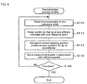
- Fig. 4 is a flowchart of the pre-correction process routine.
- CPU71 of control device 70 reads out coordinates of one reference point R (S100) and controls robot 20 so that the distal end of end effector 23 of robot 20 coincides with the coordinates (S110). Next, CPU 71 recognizes an actual stopping position then of the distal end of end effector 23 on the world coordinates (S120) and stores the stopping position as a measurement point M in HDD 73 in association with current reference point R (S130). Then, CPU 71 determines whether the pre-correction process routine ends, that is, determines whether measurement points M are stored while being individually associated with all reference points R (S140). If the determination result is negative, CPU 71 returns to S100 to execute a similar process on next reference point R. On the other hand, if the result of the determination is affirmative, CPU71 ends this pre-correction process routine.
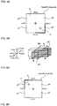
- FIG. 5 is an explanatory diagram illustrating a relationship between reference point R and measurement point M of block B where area A at height z1 and area A at height z2 make a pair of upper and lower areas.
- reference point R is (x r , yr, zi)
- measurement point M is (x r1 , y r1 , z r1 )
- reference point R is (xr, y r , z 2 )
- measurement point M is (x r2 , y r2 , z r2 ).
- the target position correction routine is a correction routine in which target position T input into robot 20 is corrected for the distal end of end effector 23 to be positioned in target portion T with good accuracy.
- CPU 71 When the target position correction routine is started, firstly, CPU 71 reads out coordinates (x t , y t , z t ) of current target position (S200). The coordinates (xt, yt, zt) of target position T are input into robot 20 in advance by an operator via input device 76 and are stored in HDD 73. Next, CPU71 sets specific block Bs (S210). Specifically, block B including target position T on the world coordinates is set as specific block Bs.
- CPU 71 sets first and second blocks B1 and B2 (S220).
- CPU 71 sets first and second blocks B1 and B2 from blocks B that are contiguous with specific block Bs.
- specific block Bs is divided into four zones of left front zone a1, right front zone a2, left rear zone a3, and right rear zone a4.
- CPU 71 recognizes which zone includes target position T and sets blocks that are individually contiguous with two external surfaces of the recognized zone as first and second blocks B1 and B2.
- left front zone a1 includes target position T.
- Fig. 7A left front zone a1 includes target position T.
- left and front blocks that are contiguous individually with two external surfaces (refer to thick solid lines in Fig. 7A ) of left front zone a1 are set as first and second blocks B1 and B2.
- right front zone a2 includes target position T.
- the right and front blocks that are contiguous individually with two external surfaces (refer to thick solid lines in Fig. 8A ) of right front zone a2 are set as first and second blocks B1 and B2.
- left rear zone a3 includes target position T. In this case, as illustrated in Fig.
- left and rear blocks that are contiguous individually with two external surfaces (refer to thick solid lines in Fig. 9A ) of left rear zone a3 are set as first and second blocks B1 and B2.
- right rear zone a4 includes target position T.
- the right and rear blocks that are contiguous individually with two external surfaces (refer to thick solid lines in Fig. 10A ) of right rear zone a4 are set as first and second blocks B1 and B2.
- CPU 71 calculates correction amounts ⁇ x t and ⁇ y t of target position T in the X- and Y-directions (S230).
- CPU71 calculates correction amounts ⁇ x t and ⁇ y t in the X- and Y-directions of target position T without taking the amount of deviation of target position T in a Z-direction into consideration.
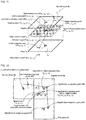
- CPU71 obtains a hypothetical projection point HP on an XY-plane at target position height zt for each of specific block Bs, first and second blocks B1 and B2.
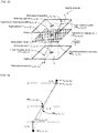
- a method for obtaining hypothetical projection point HP of specific block Bs will be described by reference to Fig. 11 .
- Specific block Bs includes a pair of upper and lower areas A. It is assumed that a height of lower area A is z 1 and a height of upper area A is z 2 .
- Measurement point M (x s1 , y s1 , z s1 ) of reference point R (x s , y s , z 1 ) in lower area A resides in a position deviating by the measured deviation amount from reference point R thereof.
- a point (xs1, ys1, z1) where this measurement point M (xs1, ys1, zs1) is projected onto lower area A is referred to as lower projection point LP.
- Lower projection point LP can be referred to as a measurement point that does not take the amount of deviation in the Z-direction into consideration.
- measurement point M (x s2 , y s2 , z s2 ) of reference point R (xs, y s , z 2 ) in upper area A resides in a position deviating by the measured deviation amount from reference point R thereof.
- a point (x s2 , y s2 , z 2 ) where this measurement point M (xs2, y s2 , z s2 ) is projected onto upper area A is referred to as upper projection point UP.
- Upper projection point UP can be referred to as a measurement point that does not take the amount of deviation in the Z-direction into consideration.
- intersection point is obtained mathematically, the intersection point being where a straight line connecting lower projection point LP with upper projection point UP intersects an XY-plane (a shaded plane in Fig. 11 ) of target position height zt.
- This intersection point constitutes a hypothetical projection point HP (xst, y st , z t ) on the XY-plane of the height zt in specific block Bs.
- Hypothetical projection point HP (x s1 , y st , z t ) can be referred to as a point where hypothetical measurement point HM (x st , y st , z st ), not illustrated, of hypothetical reference point R (xs, y s , zt) on the XY-plane of height zt is projected on the XY-plane of height zt.
- Hypothetical projection points HP of first and second blocks B1 and B2 are also obtained similarly.
- correction amounts ⁇ x t and ⁇ y t in the X- and Y-directions of target position T are calculated based on a straight line connecting together hypothetical projection point HP of specific block Bs (referred to as HPs) and hypothetical projection point of first block B1 (referred to as HP1) and a straight line connecting together hypothetical projection point HPs of specific block Bs and hypothetical projection point HP of second block B2 (referred to as HP2).
- HPs hypothetical projection point HP of specific block Bs
- HP1 hypothetical projection point of first block B1
- HP2 hypothetical projection point HP of second block B2
- HRs hypothetical reference points HR of specific block Bs, first block B1 and second block B2
- the other point is a point where a horizontal axis is an x-coordinate of hypothetical reference point HR2 and a vertical axis is a difference between an x-coordinate of hypothetical projection point HP2 and an x-coordinate of hypothetical reference point HR2.
- Correction amount ⁇ x t in the x-direction at the target position is obtained by multiplying a value obtained by dividing the obtained difference in the x-direction by the difference in the x-direction at hypothetical reference point HRs by difference ⁇ x t' .
- Correction amount ⁇ y t is also obtained in a similar manner.
- an equation of a straight line connecting the following two points is obtained.
- the other point is a point where a horizontal axis is a y-coordinate of hypothetical reference point HR2 and a vertical axis is a difference between a y-coordinate of hypothetical projection point HP2 and a y-coordinate of hypothetical reference point HR2.
- Correction amount ⁇ y t in the y-direction at the target position is obtained by multiplying a value obtained by dividing the obtained difference in the y-direction by the difference in the y-direction at hypothetical reference point HRs by difference ⁇ y t' .
- target position CT after a provisional correction is shown by a dotted "+".
- Target position CT after the provisional correction is a post-correction target position obtained provisionally without taking a deviation in the Z-direction into consideration and is (x t - ⁇ x t , y t - ⁇ y t , z t ).
- CPU 71 calculates a correction amount ⁇ z t of target position T in the Z-direction (S240).
- CPU 71 obtains an inclined plane corresponding to the XY-plane of target position height zt and calculates a correction amount ⁇ z t of the target position in the Z-direction after correction based on the inclined plane so obtained.
- CPU 71 obtains hypothetical measurement point HM corresponding to hypothetical reference point HR on the XY-plane of target position height zt for each of specific block Bs, first and second blocks B1 and B2.
- Hypothetical measurement point HM constitutes a stopping position (an estimated value) of the distal end of end effector 23 when robot 20 is controlled so that the distal end of end effector 23 temporarily coincides with the coordinates of hypothetical reference point HR.
- FIG. 13 a method for obtaining hypothetical measurement point HM of specific block Bs will be described.
- Points and positions illustrated in Fig. 13 are the same as the points and the positions illustrated in Fig. 11 .
- measurement point M (x s1 , ysi, zsi) of lower area A and measurement point M (x s2 , y s2 , z s2 ) of upper area A are connected together.
- Fig. 14 illustrates this state as viewed from a direction indicated by a white arrow (a direction indicated by arrow A) illustrated Fig. 13 .
- an equation of an inclined plane including hypothetical measurement point HM of specific block Bs (referred to as HMs), hypothetical measurement point HM of first block B1 (referred to as HM1), and hypothetical measurement point HM of second block (referred to as HM2) obtained mathematically.
- HMs hypothetical measurement point
- HM1 hypothetical measurement point of first block B1
- HM2 hypothetical measurement point HM of second block
- CPU71 calculates target position AT (x t - ⁇ x t , y t - ⁇ y t , z- ⁇ z t ) after a final correction (S250) and ends the routine.
- FCU 71 controls robot 20 so that the distal end of end effector 23 coincides with target position AT after correction.
- the distal end of end effector 23 coincides with target position T on the world coordinates with good accuracy.
- target position T is corrected by making use of not only the measured deviation amount from reference point R (the difference between the measurement point M and reference point R) of specific block Bs but also the measured amounts of deviation from reference points R of first and second blocks B1 and B2 that are contiguous with specific block Bs. Therefore, the distal end of end effector 23 can be positioned in target position T designated in the operation space of three-dimensional matrix 25.
- the two blocks residing near target position T are set as the first and second blocks. Due to this, target position T can be corrected more appropriately.
- the correction amounts in the X-direction and Y-direction of target position T are obtained based on the straight line connecting together hypothetical projection point HPs of specific block Bs and hypothetical projection point HP1 of first block B1 and the straight line connecting together hypothetical projection point HPs of specific block Bs and hypothetical projection point HP2 of second block B2. Therefore, the correction amounts in the X-direction and Y-direction of target position T can be obtained relatively easily.
- the deviation amount at target position height zt is obtained for each of specific block Bs, first block B1 and second block B2 by use of the straight line connecting together upper projection position UP and lower projection position LP and the straight line connecting together upper measurement point M and lower measurement point M. Then, the inclined plane is obtained based on the respective deviation amounts at target position height zt of specific block Bs, first block B1 and second block B2. Therefore, the correction amount in the Z-direction of target position T can be obtained relatively easily.
- a vertical articulated robot is described as functioning as robot 20 in the embodiment described above, the configuration is not limited thereto.
- an orthogonal robot, a horizontal articulated robot, a parallel link robot, or the like may be adopted as robot 20.
- the target position correction method of the present disclosure is suitable for application to the case where a vertical articulated robot is used as robot 20.
- the two blocks are set as the first and second blocks; however, the configuration is not particularly thereto.
- two blocks in four blocks that are individually contiguous with upper, lower, front, and rear surfaces of specific block Bs may be set as the first and second blocks.
- two blocks in four blocks that are individually contiguous with upper, lower, left, and right surfaces of specific block Bs may be set as the first and second blocks.
- the two blocks residing near target position T are preferably set as the first and second blocks.
- the two blocks residing near target position T are set as the first and second blocks; however, in the case where two or three blocks are contiguous with specific block Bs, the first and second block may be set without using this method.
- the first and second block may be set without using this method. For example, in the case where there are only two blocks that are contiguous with specific block Bs, such as in the case where specific block Bs resides in a corner of three-dimensional matrix 25, those two blocks should be set as the first and second blocks.
- the method for correcting a target position of a work robot according to the present disclosure may be configured as follows.
- a front block, a rear block, a left block, and a right block are respectively contiguous with the front, rear, left and right surfaces of the specific block, and two blocks may be selected from the front block, the rear block, the left block and the right block based on the target position as the first and second blocks.
- the specific block may be divided into four zones to form a left front zone, a right front zone, a left rear zone, and a right rear zone, a zone including the target position may be selected from the four zones, and blocks that are individually contiguous with two external surfaces of the selected zone may be set as the first and second blocks.
- the target position can be corrected more appropriately.
- step (b) in the method for correcting a target position of a work robot according to the present disclosure, firstly, correction amounts in the X-direction and the Y-direction of the target position may be obtained without taking the amount of deviation in the Z-direction into consideration, and then, an inclined plane (including the case of a horizontal plane) corresponding to an XY-plane including a Z-coordinate of the target position may be obtained by taking the amount of deviation in the Z-direction into consideration, so that a correction amount in the Z-direction of the target position may be obtained based on the inclined plane.
- an inclined plane including the case of a horizontal plane
- a correction amount in the Z-direction of the target position may be obtained based on the inclined plane.
- an intersection point where a straight line connecting together an upper projection position where a position deviating by the measured deviation amount from the reference point in the upper area is projected and a lower projection position where a position deviating by the measured deviation amount from the reference point in the lower area is projected intersects an XY-plane including a Z-coordinate of the target position may be obtained for each of the specific block, the first block, and the second block, and correction amounts in the X-direction and the Y-direction of the target position may be obtained based on a straight line connecting together the intersection point of the specific block and the intersection point of the first block and a straight line connecting together the intersection point of the specific block and the intersection point of the second block.
- the amount of deviation of the target position on a Z-coordinate may be obtained by use of a straight line connecting together the upper projection position and the lower projection position and a straight line connecting together a position deviating by the measured deviation amount from the reference point in the upper area and a position deviating by the measured deviation amount from the reference point in the lower area for each of the specific block, the first block, and the second block, and the inclined plane may be obtained based on the deviation amounts on the Z-coordinate of the target position of the specific block, the first block, and the second block.
- the correction amount of the target position in the Z-direction can be obtained relatively easily.
- the present disclosure can be applied to an industrial machine or the like where components are assembled together by making use of a work robot.
Landscapes
- Engineering & Computer Science (AREA)
- Robotics (AREA)
- Mechanical Engineering (AREA)
- Human Computer Interaction (AREA)
- Manufacturing & Machinery (AREA)
- Physics & Mathematics (AREA)
- General Physics & Mathematics (AREA)
- Automation & Control Theory (AREA)
- Numerical Control (AREA)
- Manipulator (AREA)
Claims (6)
- Verfahren zur Korrektur der Zielposition (T) eines Arbeitsroboters (20) in dem eine als X-Achse bezeichnete Links-Rechts-Richtung, eine als Y-Achse bezeichnete Front-Heck-Richtung und eine als Z-Achse bezeichnete Auf-Ab-Richtung, Matrixebenen, die jeweils durch kontinuierliches Verbinden von viereckigen Bereichen (A) parallel zu einer XY-Ebene in X- und Y-Richtung gebildet werden, und jeweils einen Bezugspunkt (R) aufweisen, übereinander in vorbestimmten Intervallen in einer Z-Richtung gestapelt sind, um dadurch eine dreidimensionale Matrix (25) aufzubauen, und die in einem Bearbeitungsraum der dreidimensionalen Matrix (25) bezeichnete Zielposition (T) des Arbeitsroboters (20) korrigiert wird, gekennzeichnet durch
einen rechteckigen spatförmigen-Raum umfassend ein oberes und unteres Paar der Bereiche (A), die in den vorbestimmten Intervallen angeordnet sind, der als Block (B) bezeichnet wird, und ein Block (B), der die Zielposition (T) enthält, die in dem Bearbeitungsraum der dreidimensionalen Matrix (25) bestimmt wurde, der als spezifischer Block (Bs) bezeichnet wird, wobei das Verfahren umfasst:(a) einen Schritt des Zuweisens von zwei Blöcken, die an den spezifischen Block (Bs) angrenzen, als ersten Block (B1) und zweiten Block (B2); und(b) einen Schritt des Korrigierens der Zielposition (T) basierend auf den jeweiligen Referenzpunkten (R) in einem oberen Bereich (A) und einem unteren Bereich (A) des spezifischen Blocks (Bs) und einem gemessenen Abweichungsbetrag des Arbeitsroboters (20) von den Referenzpunkten (R), jeweiligen Referenzpunkten (R) in einem oberen Bereich (A) und einem unteren Bereich (A) des ersten Blocks (B1) und einem gemessenen Abweichungsbetrag des Arbeitsroboters (20) von den Referenzpunkten (R) und den jeweiligen Referenzpunkten (R) in einem oberen Bereich (A) und einem unteren Bereich (A) des zweiten Blocks (B2) und einem gemessenen Abweichungsbetrag des Arbeitsroboters (20) von die Referenzpunkte (R). - Verfahren zur Korrektur der Zielposition (T) eines Arbeitsroboters (20) gemäß Anspruch 1, wobei
in Schritt (a) ein vorderer Block (B), ein hinterer Block (B), ein linker Block (B) und ein rechter Block (B) jeweils an die vordere, hintere, linke und rechte Oberfläche des spezifischen Blocks (Bs) angrenzen und zwei Blöcke (B) aus dem vorderen Block (B), dem hinteren Block (B), dem linken Block (B) und dem rechten Block (B) als erster und zweiter Block (B1, B2) basierend auf der Zielposition (T) ausgewählt werden. - Verfahren zur Korrektur der Zielposition (T) eines Arbeitsroboters (20) gemäß Anspruch 2, wobei
in Schritt (a) der spezifische Block (Bs) in vier Zonen unterteilt wird, um eine linke vordere Zone (a1), eine rechte vordere Zone (a2), eine linke hintere Zone (a3) und eine rechte hintere Zone (a4) zu bilden, wobei eine Zone aus den vier Zonen (a1, a2, a3, a4) welche die Zielposition (T) beinhaltet ausgewählt wird, und Blöcke (B), die einzeln an zwei Außenflächen der ausgewählten Zone angrenzen, als erste und zweite Blöcke (B1, B2) eingestellt werden. - Verfahren zur Korrektur der Zielposition (T) eines Arbeitsroboters (20) gemäß einem der Ansprüche 1 bis 3, wobei
in Schritt (b) zuerst Korrekturbeträge in einer X-Richtung und einer Y-Richtung der Zielposition (T) erhalten werden, ohne einen Betrag der Abweichung in einer Z-Richtung zu berücksichtigen, dann eine schiefe Ebene, einschließlich einer horizontalen Ebene, die einer XY-Ebene mit einer Z-Koordinate der Zielposition (T) entspricht, erhalten wird, indem ein Betrag der Abweichung in der Z-Richtung berücksichtigt wird und ein Korrekturbetrag der Zielposition (T) in der Z-Richtung basierend auf der schiefen Ebene erhalten wird. - Verfahren zur Korrektur der Zielposition (T) eines Arbeitsroboters (20) gemäß Anspruch 4, wobei
in Schritt (b), beim Erhalten der Korrekturbeträge in der X-Richtung und der Y-Richtung der Zielposition (T), ohne den Betrag der Abweichung in der Z-Richtung zu nehmen, ein Schnittpunkt, an dem eine gerade Linie, welche eine obere Projektionsposition, bei der eine Position projiziert wird, die um den gemessenen Abweichungsbetrag vom Referenzpunkt (R) im oberen Bereich (A) abweicht, und eine untere Projektionsposition, bei der eine Position, die um den gemessenen Abweichungsbetrag vom Referenzpunkt (R) im unteren Bereich (A) abweicht, verbindet, eine XY-Ebene schneidet, die eine Z-Koordinate der Zielposition (T) enthält, für jeden der spezifischen Blöcke (Bs), den ersten Block (B1) und den zweiten Block (B2) erhalten wird und Korrekturbeträge in X-Richtung und Y-Richtung der Zielposition (T) basierend auf einer geraden Linie, die den Schnittpunkt des spezifischen Blocks (Bs) und den Schnittpunkt des ersten Blocks (B1) miteinander verbindet und einer gerade Linie, die den Schnittpunkt des spezifischen Blocks (Bs) und den Schnittpunkt des zweiten Blocks (B2) miteinander verbindet, erhalten werden. - Verfahren zur Korrektur der Zielposition (T) eines Arbeitsroboters (20) gemäß Anspruch 4 oder 5, wobei
in Schritt (b), beim Erhalten der schiefen Ebene zur Verwendung des Erhaltens eines Korrekturbetrags in der Z-Richtung der Zielposition (T) unter Berücksichtigung des Betrags der Abweichung in der Z-Richtung, ein Betrag der Abweichung von der Zielposition (T) auf einer Z-Koordinate unter Verwendung einer geraden Linie, welche die obere Projektionsposition und die untere Projektionsposition miteinander verbindet, und einer geraden Linie, die eine Position, die um den gemessenen Abweichungsbetrag vom Referenzpunkt (R) im oberen Bereich (A) abweicht, und eine Position, die um den gemessenen Abweichungsbetrag vom Referenzpunkt (R) im unteren Bereich (A) abweicht, verbindet, für jeden der spezifischen Blöcke (Bs), des ersten Blocks (B1) und des zweiten Blocks (B2) erhalten wird und die schiefe Ebene basierend auf dem Abweichungsbetrag auf der Z-Koordinate der Zielposition (T) für jeden des spezifischen Blocks (Bs), des ersten Blocks (B1) und des zweiten Blocks (B2) erhalten wird.
Applications Claiming Priority (1)
| Application Number | Priority Date | Filing Date | Title |
|---|---|---|---|
| PCT/JP2016/087024 WO2018109828A1 (ja) | 2016-12-13 | 2016-12-13 | 作業ロボットの目的位置補正方法 |
Publications (3)
| Publication Number | Publication Date |
|---|---|
| EP3556519A1 EP3556519A1 (de) | 2019-10-23 |
| EP3556519A4 EP3556519A4 (de) | 2019-12-25 |
| EP3556519B1 true EP3556519B1 (de) | 2020-12-02 |
Family
ID=62559407
Family Applications (1)
| Application Number | Title | Priority Date | Filing Date |
|---|---|---|---|
| EP16924068.6A Active EP3556519B1 (de) | 2016-12-13 | 2016-12-13 | Verfahren zur korrektur der zielposition eines arbeitsroboters |
Country Status (5)
| Country | Link |
|---|---|
| US (1) | US10940586B2 (de) |
| EP (1) | EP3556519B1 (de) |
| JP (1) | JP6705017B2 (de) |
| CN (1) | CN110072675B (de) |
| WO (1) | WO2018109828A1 (de) |
Families Citing this family (3)
| Publication number | Priority date | Publication date | Assignee | Title |
|---|---|---|---|---|
| CN114450130A (zh) * | 2019-09-27 | 2022-05-06 | 日本电产株式会社 | 高度校正系统 |
| WO2021060228A1 (ja) * | 2019-09-27 | 2021-04-01 | 日本電産株式会社 | 高さ補正システム |
| CN117773940B (zh) * | 2024-01-11 | 2024-07-16 | 四川大学 | 一种多因素影响下工业机器人绝对定位误差预测补偿方法 |
Family Cites Families (31)
| Publication number | Priority date | Publication date | Assignee | Title |
|---|---|---|---|---|
| JPS59189415A (ja) * | 1983-04-13 | 1984-10-27 | Hitachi Ltd | 工業用ロボツトの動作教示方法および装置 |
| JPS6337402A (ja) * | 1986-08-01 | 1988-02-18 | Mitsui Seiki Kogyo Co Ltd | 数値制御工作機械における立体位置補正方法 |
| JPS63133699A (ja) * | 1986-11-26 | 1988-06-06 | シチズン時計株式会社 | 電子部品自動挿入機における部品挿入位置補正方法 |
| JP2562353B2 (ja) * | 1988-08-03 | 1996-12-11 | 株式会社三協精機製作所 | ロボットの位置決め方法 |
| DE69033605T2 (de) * | 1989-05-17 | 2001-08-16 | Fujitsu Ltd., Kawasaki | Profilsteuerungssystem für Roboter |
| JP2666512B2 (ja) * | 1990-03-30 | 1997-10-22 | トヨタ自動車株式会社 | 機械座標系補正装置 |
| JPH04233602A (ja) * | 1990-12-28 | 1992-08-21 | Fanuc Ltd | ロボットのたわみ補正方法及びたわみ認識方法 |
| JPH06348322A (ja) * | 1993-06-07 | 1994-12-22 | Fanuc Ltd | ロボットのオフライン教示方法 |
| JP3215086B2 (ja) * | 1998-07-09 | 2001-10-02 | ファナック株式会社 | ロボット制御装置 |
| JP3808321B2 (ja) * | 2001-04-16 | 2006-08-09 | ファナック株式会社 | ロボット制御装置 |
| DE10155430B4 (de) * | 2001-11-12 | 2006-12-14 | Siemens Ag | Adaption von Kompensationsdaten zur Verringerung von Stellungsfehlern bei Werkzeugmaschinen und Robotern |
| JP4128156B2 (ja) * | 2004-06-03 | 2008-07-30 | 松下電器産業株式会社 | 部品実装方法及び装置 |
| WO2009057229A1 (ja) * | 2007-11-02 | 2009-05-07 | Makino Milling Machine Co., Ltd. | エラーマップ作成方法及び装置並びにエラーマップ作成機能を有した数値制御工作機械 |
| JP4888374B2 (ja) | 2007-12-20 | 2012-02-29 | 株式会社デンソーウェーブ | ロボットの動作制御装置及びその動作制御方法 |
| JP2010152550A (ja) * | 2008-12-24 | 2010-07-08 | Canon Inc | 作業装置及びその校正方法 |
| JP5528095B2 (ja) * | 2009-12-22 | 2014-06-25 | キヤノン株式会社 | ロボットシステム、その制御装置及び方法 |
| JP6228120B2 (ja) * | 2012-08-02 | 2017-11-08 | 富士機械製造株式会社 | 多関節型ロボットを備えた作業機および電気部品装着機 |
| JP6108860B2 (ja) * | 2013-02-14 | 2017-04-05 | キヤノン株式会社 | ロボットシステム及びロボットシステムの制御方法 |
| JP5678979B2 (ja) * | 2013-03-15 | 2015-03-04 | 株式会社安川電機 | ロボットシステム、校正方法及び被加工物の製造方法 |
| JP5956952B2 (ja) * | 2013-05-10 | 2016-07-27 | 株式会社牧野フライス製作所 | 数値制御工作機械 |
| JP6335460B2 (ja) * | 2013-09-26 | 2018-05-30 | キヤノン株式会社 | ロボットシステムの制御装置及び指令値生成方法、並びにロボットシステムの制御方法 |
| US10525597B2 (en) * | 2014-11-21 | 2020-01-07 | Seiko Epson Corporation | Robot and robot system |
| JP6126067B2 (ja) * | 2014-11-28 | 2017-05-10 | ファナック株式会社 | 工作機械及びロボットを備えた協働システム |
| JP6259401B2 (ja) * | 2015-01-16 | 2018-01-10 | 矢崎総業株式会社 | 位置合わせ方法 |
| JP2016221645A (ja) * | 2015-06-02 | 2016-12-28 | セイコーエプソン株式会社 | ロボット、ロボット制御装置およびロボットシステム |
| WO2018092236A1 (ja) * | 2016-11-17 | 2018-05-24 | 株式会社Fuji | 作業ロボットおよび作業位置補正方法 |
| JP6860843B2 (ja) * | 2017-02-20 | 2021-04-21 | 株式会社安川電機 | ロボットシステム、ロボット制御装置、及びロボット制御方法 |
| JP6967715B2 (ja) * | 2017-04-18 | 2021-11-17 | パナソニックIpマネジメント株式会社 | カメラ校正方法、カメラ校正プログラム及びカメラ校正装置 |
| JP6445092B2 (ja) * | 2017-05-31 | 2018-12-26 | ファナック株式会社 | ロボットの教示のための情報を表示するロボットシステム |
| JP6572262B2 (ja) * | 2017-06-06 | 2019-09-04 | ファナック株式会社 | 教示位置修正装置および教示位置修正方法 |
| JP6897396B2 (ja) * | 2017-07-28 | 2021-06-30 | セイコーエプソン株式会社 | 制御装置、ロボットシステムおよび制御方法 |
-
2016
- 2016-12-13 US US16/466,072 patent/US10940586B2/en active Active
- 2016-12-13 CN CN201680091504.6A patent/CN110072675B/zh active Active
- 2016-12-13 JP JP2018556060A patent/JP6705017B2/ja active Active
- 2016-12-13 WO PCT/JP2016/087024 patent/WO2018109828A1/ja not_active Ceased
- 2016-12-13 EP EP16924068.6A patent/EP3556519B1/de active Active
Non-Patent Citations (1)
| Title |
|---|
| None * |
Also Published As
| Publication number | Publication date |
|---|---|
| JP6705017B2 (ja) | 2020-06-03 |
| CN110072675A (zh) | 2019-07-30 |
| US10940586B2 (en) | 2021-03-09 |
| CN110072675B (zh) | 2022-04-19 |
| EP3556519A4 (de) | 2019-12-25 |
| WO2018109828A1 (ja) | 2018-06-21 |
| US20200061812A1 (en) | 2020-02-27 |
| JPWO2018109828A1 (ja) | 2019-08-08 |
| EP3556519A1 (de) | 2019-10-23 |
Similar Documents
| Publication | Publication Date | Title |
|---|---|---|
| US10099365B2 (en) | Work machine provided with articulated robot and electric component mounting machine | |
| US11072078B2 (en) | Method for measuring pose of robotic end tool | |
| CN109996653B (zh) | 作业位置校正方法及作业机器人 | |
| US10537995B2 (en) | Controller and control method of robot, and robot system | |
| EP1676679A2 (de) | Robotische Steuereinheit zur Positionskorrektur einer Roboterhand mittels einem optischen Sensor | |
| JP2018083284A (ja) | ロボット制御装置、ロボット、ロボットシステム、及び、ロボット制御方法 | |
| US11173608B2 (en) | Work robot and work position correction method | |
| EP3556519B1 (de) | Verfahren zur korrektur der zielposition eines arbeitsroboters | |
| US7957834B2 (en) | Method for calculating rotation center point and axis of rotation, method for generating program, method for moving manipulator and positioning device, and robotic system | |
| CN110402190B (zh) | 机器人系统 | |
| JP3978844B2 (ja) | 移動体の停止位置ズレ量検出装置及び無人搬送車 | |
| JP2932445B2 (ja) | カメラ座標系ずれ補正方法 | |
| KR102253409B1 (ko) | 워크 유지 기구 | |
| JP7660686B2 (ja) | ロボット制御装置、ロボット制御システム、及びロボット制御方法 | |
| JP7510514B2 (ja) | オフセット値設定方法およびロボット制御装置 | |
| JP2562353B2 (ja) | ロボットの位置決め方法 | |
| JP2759675B2 (ja) | センサロボット | |
| JP4798552B2 (ja) | ロボットの領域監視方法および制御装置 | |
| JP2024102425A (ja) | 補正方法、補正システム、および、プログラム | |
| JP2017074637A (ja) | ツールセンターポイント推定方法、ツールセンターポイント推定装置 |
Legal Events
| Date | Code | Title | Description |
|---|---|---|---|
| STAA | Information on the status of an ep patent application or granted ep patent |
Free format text: STATUS: THE INTERNATIONAL PUBLICATION HAS BEEN MADE |
|
| PUAI | Public reference made under article 153(3) epc to a published international application that has entered the european phase |
Free format text: ORIGINAL CODE: 0009012 |
|
| STAA | Information on the status of an ep patent application or granted ep patent |
Free format text: STATUS: REQUEST FOR EXAMINATION WAS MADE |
|
| 17P | Request for examination filed |
Effective date: 20190529 |
|
| AK | Designated contracting states |
Kind code of ref document: A1 Designated state(s): AL AT BE BG CH CY CZ DE DK EE ES FI FR GB GR HR HU IE IS IT LI LT LU LV MC MK MT NL NO PL PT RO RS SE SI SK SM TR |
|
| AX | Request for extension of the european patent |
Extension state: BA ME |
|
| A4 | Supplementary search report drawn up and despatched |
Effective date: 20191122 |
|
| RIC1 | Information provided on ipc code assigned before grant |
Ipc: B25J 9/16 20060101ALI20191118BHEP Ipc: B25J 9/10 20060101AFI20191118BHEP Ipc: G05B 19/408 20060101ALI20191118BHEP |
|
| DAV | Request for validation of the european patent (deleted) | ||
| DAX | Request for extension of the european patent (deleted) | ||
| GRAP | Despatch of communication of intention to grant a patent |
Free format text: ORIGINAL CODE: EPIDOSNIGR1 |
|
| STAA | Information on the status of an ep patent application or granted ep patent |
Free format text: STATUS: GRANT OF PATENT IS INTENDED |
|
| INTG | Intention to grant announced |
Effective date: 20200720 |
|
| GRAS | Grant fee paid |
Free format text: ORIGINAL CODE: EPIDOSNIGR3 |
|
| GRAA | (expected) grant |
Free format text: ORIGINAL CODE: 0009210 |
|
| STAA | Information on the status of an ep patent application or granted ep patent |
Free format text: STATUS: THE PATENT HAS BEEN GRANTED |
|
| AK | Designated contracting states |
Kind code of ref document: B1 Designated state(s): AL AT BE BG CH CY CZ DE DK EE ES FI FR GB GR HR HU IE IS IT LI LT LU LV MC MK MT NL NO PL PT RO RS SE SI SK SM TR |
|
| REG | Reference to a national code |
Ref country code: GB Ref legal event code: FG4D |
|
| REG | Reference to a national code |
Ref country code: AT Ref legal event code: REF Ref document number: 1340392 Country of ref document: AT Kind code of ref document: T Effective date: 20201215 Ref country code: CH Ref legal event code: EP |
|
| REG | Reference to a national code |
Ref country code: DE Ref legal event code: R096 Ref document number: 602016049287 Country of ref document: DE |
|
| REG | Reference to a national code |
Ref country code: IE Ref legal event code: FG4D |
|
| PG25 | Lapsed in a contracting state [announced via postgrant information from national office to epo] |
Ref country code: FI Free format text: LAPSE BECAUSE OF FAILURE TO SUBMIT A TRANSLATION OF THE DESCRIPTION OR TO PAY THE FEE WITHIN THE PRESCRIBED TIME-LIMIT Effective date: 20201202 Ref country code: GR Free format text: LAPSE BECAUSE OF FAILURE TO SUBMIT A TRANSLATION OF THE DESCRIPTION OR TO PAY THE FEE WITHIN THE PRESCRIBED TIME-LIMIT Effective date: 20210303 Ref country code: RS Free format text: LAPSE BECAUSE OF FAILURE TO SUBMIT A TRANSLATION OF THE DESCRIPTION OR TO PAY THE FEE WITHIN THE PRESCRIBED TIME-LIMIT Effective date: 20201202 Ref country code: NO Free format text: LAPSE BECAUSE OF FAILURE TO SUBMIT A TRANSLATION OF THE DESCRIPTION OR TO PAY THE FEE WITHIN THE PRESCRIBED TIME-LIMIT Effective date: 20210302 |
|
| REG | Reference to a national code |
Ref country code: NL Ref legal event code: MP Effective date: 20201202 |
|
| REG | Reference to a national code |
Ref country code: AT Ref legal event code: MK05 Ref document number: 1340392 Country of ref document: AT Kind code of ref document: T Effective date: 20201202 |
|
| PG25 | Lapsed in a contracting state [announced via postgrant information from national office to epo] |
Ref country code: SE Free format text: LAPSE BECAUSE OF FAILURE TO SUBMIT A TRANSLATION OF THE DESCRIPTION OR TO PAY THE FEE WITHIN THE PRESCRIBED TIME-LIMIT Effective date: 20201202 Ref country code: BG Free format text: LAPSE BECAUSE OF FAILURE TO SUBMIT A TRANSLATION OF THE DESCRIPTION OR TO PAY THE FEE WITHIN THE PRESCRIBED TIME-LIMIT Effective date: 20210302 Ref country code: PL Free format text: LAPSE BECAUSE OF FAILURE TO SUBMIT A TRANSLATION OF THE DESCRIPTION OR TO PAY THE FEE WITHIN THE PRESCRIBED TIME-LIMIT Effective date: 20201202 Ref country code: LV Free format text: LAPSE BECAUSE OF FAILURE TO SUBMIT A TRANSLATION OF THE DESCRIPTION OR TO PAY THE FEE WITHIN THE PRESCRIBED TIME-LIMIT Effective date: 20201202 |
|
| PG25 | Lapsed in a contracting state [announced via postgrant information from national office to epo] |
Ref country code: NL Free format text: LAPSE BECAUSE OF FAILURE TO SUBMIT A TRANSLATION OF THE DESCRIPTION OR TO PAY THE FEE WITHIN THE PRESCRIBED TIME-LIMIT Effective date: 20201202 Ref country code: HR Free format text: LAPSE BECAUSE OF FAILURE TO SUBMIT A TRANSLATION OF THE DESCRIPTION OR TO PAY THE FEE WITHIN THE PRESCRIBED TIME-LIMIT Effective date: 20201202 |
|
| REG | Reference to a national code |
Ref country code: LT Ref legal event code: MG9D |
|
| PG25 | Lapsed in a contracting state [announced via postgrant information from national office to epo] |
Ref country code: CZ Free format text: LAPSE BECAUSE OF FAILURE TO SUBMIT A TRANSLATION OF THE DESCRIPTION OR TO PAY THE FEE WITHIN THE PRESCRIBED TIME-LIMIT Effective date: 20201202 Ref country code: EE Free format text: LAPSE BECAUSE OF FAILURE TO SUBMIT A TRANSLATION OF THE DESCRIPTION OR TO PAY THE FEE WITHIN THE PRESCRIBED TIME-LIMIT Effective date: 20201202 Ref country code: LT Free format text: LAPSE BECAUSE OF FAILURE TO SUBMIT A TRANSLATION OF THE DESCRIPTION OR TO PAY THE FEE WITHIN THE PRESCRIBED TIME-LIMIT Effective date: 20201202 Ref country code: SM Free format text: LAPSE BECAUSE OF FAILURE TO SUBMIT A TRANSLATION OF THE DESCRIPTION OR TO PAY THE FEE WITHIN THE PRESCRIBED TIME-LIMIT Effective date: 20201202 Ref country code: PT Free format text: LAPSE BECAUSE OF FAILURE TO SUBMIT A TRANSLATION OF THE DESCRIPTION OR TO PAY THE FEE WITHIN THE PRESCRIBED TIME-LIMIT Effective date: 20210405 Ref country code: SK Free format text: LAPSE BECAUSE OF FAILURE TO SUBMIT A TRANSLATION OF THE DESCRIPTION OR TO PAY THE FEE WITHIN THE PRESCRIBED TIME-LIMIT Effective date: 20201202 Ref country code: RO Free format text: LAPSE BECAUSE OF FAILURE TO SUBMIT A TRANSLATION OF THE DESCRIPTION OR TO PAY THE FEE WITHIN THE PRESCRIBED TIME-LIMIT Effective date: 20201202 |
|
| REG | Reference to a national code |
Ref country code: CH Ref legal event code: PL |
|
| PG25 | Lapsed in a contracting state [announced via postgrant information from national office to epo] |
Ref country code: AT Free format text: LAPSE BECAUSE OF FAILURE TO SUBMIT A TRANSLATION OF THE DESCRIPTION OR TO PAY THE FEE WITHIN THE PRESCRIBED TIME-LIMIT Effective date: 20201202 |
|
| REG | Reference to a national code |
Ref country code: DE Ref legal event code: R097 Ref document number: 602016049287 Country of ref document: DE Ref country code: BE Ref legal event code: MM Effective date: 20201231 |
|
| PG25 | Lapsed in a contracting state [announced via postgrant information from national office to epo] |
Ref country code: IS Free format text: LAPSE BECAUSE OF FAILURE TO SUBMIT A TRANSLATION OF THE DESCRIPTION OR TO PAY THE FEE WITHIN THE PRESCRIBED TIME-LIMIT Effective date: 20210402 Ref country code: MC Free format text: LAPSE BECAUSE OF FAILURE TO SUBMIT A TRANSLATION OF THE DESCRIPTION OR TO PAY THE FEE WITHIN THE PRESCRIBED TIME-LIMIT Effective date: 20201202 |
|
| PLBE | No opposition filed within time limit |
Free format text: ORIGINAL CODE: 0009261 |
|
| STAA | Information on the status of an ep patent application or granted ep patent |
Free format text: STATUS: NO OPPOSITION FILED WITHIN TIME LIMIT |
|
| PG25 | Lapsed in a contracting state [announced via postgrant information from national office to epo] |
Ref country code: FR Free format text: LAPSE BECAUSE OF NON-PAYMENT OF DUE FEES Effective date: 20210202 Ref country code: LU Free format text: LAPSE BECAUSE OF NON-PAYMENT OF DUE FEES Effective date: 20201213 Ref country code: IT Free format text: LAPSE BECAUSE OF FAILURE TO SUBMIT A TRANSLATION OF THE DESCRIPTION OR TO PAY THE FEE WITHIN THE PRESCRIBED TIME-LIMIT Effective date: 20201202 Ref country code: IE Free format text: LAPSE BECAUSE OF NON-PAYMENT OF DUE FEES Effective date: 20201213 Ref country code: AL Free format text: LAPSE BECAUSE OF FAILURE TO SUBMIT A TRANSLATION OF THE DESCRIPTION OR TO PAY THE FEE WITHIN THE PRESCRIBED TIME-LIMIT Effective date: 20201202 |
|
| 26N | No opposition filed |
Effective date: 20210903 |
|
| GBPC | Gb: european patent ceased through non-payment of renewal fee |
Effective date: 20210302 |
|
| PG25 | Lapsed in a contracting state [announced via postgrant information from national office to epo] |
Ref country code: SI Free format text: LAPSE BECAUSE OF FAILURE TO SUBMIT A TRANSLATION OF THE DESCRIPTION OR TO PAY THE FEE WITHIN THE PRESCRIBED TIME-LIMIT Effective date: 20201202 Ref country code: CH Free format text: LAPSE BECAUSE OF NON-PAYMENT OF DUE FEES Effective date: 20201231 Ref country code: DK Free format text: LAPSE BECAUSE OF FAILURE TO SUBMIT A TRANSLATION OF THE DESCRIPTION OR TO PAY THE FEE WITHIN THE PRESCRIBED TIME-LIMIT Effective date: 20201202 Ref country code: LI Free format text: LAPSE BECAUSE OF NON-PAYMENT OF DUE FEES Effective date: 20201231 |
|
| PG25 | Lapsed in a contracting state [announced via postgrant information from national office to epo] |
Ref country code: GB Free format text: LAPSE BECAUSE OF NON-PAYMENT OF DUE FEES Effective date: 20210302 Ref country code: ES Free format text: LAPSE BECAUSE OF FAILURE TO SUBMIT A TRANSLATION OF THE DESCRIPTION OR TO PAY THE FEE WITHIN THE PRESCRIBED TIME-LIMIT Effective date: 20201202 |
|
| PG25 | Lapsed in a contracting state [announced via postgrant information from national office to epo] |
Ref country code: IS Free format text: LAPSE BECAUSE OF FAILURE TO SUBMIT A TRANSLATION OF THE DESCRIPTION OR TO PAY THE FEE WITHIN THE PRESCRIBED TIME-LIMIT Effective date: 20210402 Ref country code: TR Free format text: LAPSE BECAUSE OF FAILURE TO SUBMIT A TRANSLATION OF THE DESCRIPTION OR TO PAY THE FEE WITHIN THE PRESCRIBED TIME-LIMIT Effective date: 20201202 Ref country code: MT Free format text: LAPSE BECAUSE OF FAILURE TO SUBMIT A TRANSLATION OF THE DESCRIPTION OR TO PAY THE FEE WITHIN THE PRESCRIBED TIME-LIMIT Effective date: 20201202 Ref country code: CY Free format text: LAPSE BECAUSE OF FAILURE TO SUBMIT A TRANSLATION OF THE DESCRIPTION OR TO PAY THE FEE WITHIN THE PRESCRIBED TIME-LIMIT Effective date: 20201202 |
|
| PG25 | Lapsed in a contracting state [announced via postgrant information from national office to epo] |
Ref country code: MK Free format text: LAPSE BECAUSE OF FAILURE TO SUBMIT A TRANSLATION OF THE DESCRIPTION OR TO PAY THE FEE WITHIN THE PRESCRIBED TIME-LIMIT Effective date: 20201202 |
|
| PG25 | Lapsed in a contracting state [announced via postgrant information from national office to epo] |
Ref country code: BE Free format text: LAPSE BECAUSE OF NON-PAYMENT OF DUE FEES Effective date: 20201231 |
|
| P01 | Opt-out of the competence of the unified patent court (upc) registered |
Effective date: 20230328 |
|
| PGFP | Annual fee paid to national office [announced via postgrant information from national office to epo] |
Ref country code: DE Payment date: 20251028 Year of fee payment: 10 |