EP3556514A1 - Öffnende und schliessende handhaltbare vorrichtung und winkelverstellverfahren für handhaltbaren abschnitt davon - Google Patents
Öffnende und schliessende handhaltbare vorrichtung und winkelverstellverfahren für handhaltbaren abschnitt davon Download PDFInfo
- Publication number
- EP3556514A1 EP3556514A1 EP16923931.6A EP16923931A EP3556514A1 EP 3556514 A1 EP3556514 A1 EP 3556514A1 EP 16923931 A EP16923931 A EP 16923931A EP 3556514 A1 EP3556514 A1 EP 3556514A1
- Authority
- EP
- European Patent Office
- Prior art keywords
- handheld
- open
- axle pin
- close
- clamping
- Prior art date
- Legal status (The legal status is an assumption and is not a legal conclusion. Google has not performed a legal analysis and makes no representation as to the accuracy of the status listed.)
- Granted
Links
Images


Classifications
-
- B—PERFORMING OPERATIONS; TRANSPORTING
- B25—HAND TOOLS; PORTABLE POWER-DRIVEN TOOLS; MANIPULATORS
- B25B—TOOLS OR BENCH DEVICES NOT OTHERWISE PROVIDED FOR, FOR FASTENING, CONNECTING, DISENGAGING, OR HOLDING
- B25B7/00—Pliers; Other hand-held gripping tools with jaws on pivoted limbs; Details applicable generally to pivoted-limb hand tools
- B25B7/18—Adjusting means for the operating arms
-
- B—PERFORMING OPERATIONS; TRANSPORTING
- B25—HAND TOOLS; PORTABLE POWER-DRIVEN TOOLS; MANIPULATORS
- B25B—TOOLS OR BENCH DEVICES NOT OTHERWISE PROVIDED FOR, FOR FASTENING, CONNECTING, DISENGAGING, OR HOLDING
- B25B7/00—Pliers; Other hand-held gripping tools with jaws on pivoted limbs; Details applicable generally to pivoted-limb hand tools
- B25B7/12—Pliers; Other hand-held gripping tools with jaws on pivoted limbs; Details applicable generally to pivoted-limb hand tools involving special transmission means between the handles and the jaws, e.g. toggle levers, gears
-
- B—PERFORMING OPERATIONS; TRANSPORTING
- B25—HAND TOOLS; PORTABLE POWER-DRIVEN TOOLS; MANIPULATORS
- B25B—TOOLS OR BENCH DEVICES NOT OTHERWISE PROVIDED FOR, FOR FASTENING, CONNECTING, DISENGAGING, OR HOLDING
- B25B7/00—Pliers; Other hand-held gripping tools with jaws on pivoted limbs; Details applicable generally to pivoted-limb hand tools
- B25B7/06—Joints
- B25B7/08—Joints with fixed fulcrum
-
- B—PERFORMING OPERATIONS; TRANSPORTING
- B25—HAND TOOLS; PORTABLE POWER-DRIVEN TOOLS; MANIPULATORS
- B25B—TOOLS OR BENCH DEVICES NOT OTHERWISE PROVIDED FOR, FOR FASTENING, CONNECTING, DISENGAGING, OR HOLDING
- B25B7/00—Pliers; Other hand-held gripping tools with jaws on pivoted limbs; Details applicable generally to pivoted-limb hand tools
- B25B7/14—Locking means
-
- B—PERFORMING OPERATIONS; TRANSPORTING
- B25—HAND TOOLS; PORTABLE POWER-DRIVEN TOOLS; MANIPULATORS
- B25G—HANDLES FOR HAND IMPLEMENTS
- B25G1/00—Handle constructions
- B25G1/06—Handle constructions reversible or adjustable for position
Definitions
- the present invention relates to the field of handheld tools, particularly to an open-close handheld apparatus and a method of adjustment of the angle between the handheld portions thereof.
- the invention relates to a type of open-close handheld apparatus, including clamping tools and cutting tools and the like.
- Typical open-close handheld apparatus such as nipper pliers, scissors and the like, are generally integrally made of handheld portions and clamping portions.
- the angle between the two handheld portions is the same as the angle between the two clamping portions.
- the length of the handheld portions are set to be 3 times longer than the length of the clamping portions for saving effort.
- the angles between the clamping portions and between the handheld portions are larger accordingly, and the distance between end parts of the two handheld portions is also larger after being opened.
- the user is not able to exert force with one hand to the end parts of the two handheld portions due to the limited opening area of the hand of the user, and cannot successfully complete the operation.
- the user is forced to be only able to exert force to the middle parts of the two handheld portions, and thus due to the smaller moment of force it is strenuous and inconvenient for the user to operate and use.
- the person skilled in the art are devoted to developing an open-close handheld tool with the handheld portions thereof being rotatable relative to the clamping portions in the open-close direction of the clamping portions and being locked in position, so that the user can autonomously adjust the relative angle between the handheld portion and the clamping portion of the handheld tool in the open-close direction according to the size of the use's hand and the habit of exerting force, and lock the handheld tool, so that the user can operate and use the handheld tool in an angle which is most familiar to the users and most convenient to use.
- the object of the invention is to provide an open-close handheld apparatus in order to solve the technical problems such as the inconvenience when operating and using the open-close handheld apparatus of the prior art under special application conditions.
- the invention provides an open-close handheld apparatus, including a first member and a second member, the first member includes a first clamping portion and a first handheld portion; the second member includes a second clamping portion and a second handheld portion, the first and second clamping portions are rotatably and movably connected via a first axle pin, the first and second clamping portions open and close relative to each other, the plane in which the open-close path thereof is located being an open-close plane; the first handheld portion is rotatably connected to the first clamping portion, the plane in which the rotation path of the first handheld portion is located is the same as or parallel to the open-close plane; a locking arrangement is provided at the joint between the first handheld portion and the first clamping portion, used for locking or unlocking the first handheld portion and the first clamping portion.
- the invention provides another open-close handheld apparatus, including a first member and a second member, the first member includes a first clamping portion and a first handheld portion; the second member includes a second clamping portion and a second handheld portion, the first and second clamping portions are rotatably and movably connected via a first axle pin, the first and second clamping portions open and close relative to each other, the plane in which the open-close path thereof is located being an open-close plane; the first handheld portion is rotatably connected to the first clamping portion, the plane in which the rotation path of the first handheld portion is located is the same as or parallel to the open-close plane; a locking arrangement is provided at the joint between the first handheld portion and the first clamping portion, used for locking or unlocking the first handheld portion and the first clamping portion.
- the second handheld portion is rotatably connected to the second clamping portion, the plane in which the rotation path of the second handheld portion is located is the same as or parallel to the open-close plane, a locking arrangement is provided at the joint between the second handheld portion and the second clamping portion, used for locking or unlocking the second handheld portion and the second clamping portion.
- the locking arrangement includes an extending portion provided at the bottom end of the first or second clamping portion, a protruding portion provided at the top end of the first or second handheld portion and inserted into the extending portion, a second axle pin passing through the extending portion and the protruding portion; wherein the protruding portion is movably connected to the extending portion via the second axle pin.
- the extending portion includes a first mounting plate, a second mounting plate oppositely arranged relative to the first mounting plate, an assembly groove provided between the first mounting plate and the second mounting plate, used for inserting into the protruding portion.
- the shape and size of the second mounting plate conform to those of the first mounting plate.
- the first mounting plate includes a first mounting hole
- the second mounting plate includes a second mounting hole oppositely arranged relative to the first mounting hole
- the protruding portion includes a third mounting hole, when the protruding portion is inserted into the assembly groove, the second axle pin successively passes through the first mounting hole, the third mounting hole and the second mounting hole.
- the locking arrangement further includes a first press plate provided at the top part of the second axle pin, annular sawteeth provided on the inner side walls of the first mounting hole, the third mounting hole and the second mounting hole, a spline block sheathed on the outside of the second axle pin, two or more first racks being evenly distributed on the outer side walls of the spline block, the first racks being parallel to the second axle pin, a first spring sheathed on the outside of the second axle pin, the top end of the first spring connected to the bottom part of the first press plate, the bottom end of the first spring sheathed on the top part of the spline block, and a nut threadedly connected to the lower end of the second axle pin.
- each of the first racks from the top part to the bottom part thereof, successively includes a first notch, a first widened tooth, a second notch and a second widened tooth, when the press button is pressed downward, the first widened teeth engage with the annular sawteeth in the third mounting hole, and the locking arrangement is in the unlocked state; when the press button is released, the first widened teeth engage with the annular sawteeth in the first mounting hole and the third mounting hole, the second widened teeth engage with the annular sawteeth in the second mounting hole, and the locking arrangement is in the locked state.
- the length of the first widened tooth is less than the depth of the third mounting hole
- the length of the second widened tooth is less than the maximum compression distance of the first spring
- the length of the second notch is greater than the depth of the third mounting hole.
- the locking arrangement further includes a press button groove arranged at the top part of the first mounting plate and located above the first mounting hole, for placing the first press plate, a nut groove arranged at the bottom part of the second mounting plate and located below the second mounting hole, for placing the nut.
- the locking arrangement further includes angle marks provided at the top part of the first mounting plate and located around the press button groove, for marking the rotation angle of the first handheld portion relative to the first clamping portion, or for marking the rotation angle of the second handheld portion relative to the second clamping portion, positioning marks provided at the top part of the first handheld portion or the second handheld portion and being adjacent to one end of the protruding portion, the positioning marks pointing to any angle among the angle marks.
- the locking arrangement further includes a semi-circular gear formed at an end of the first mounting plate and/or the second mounting plate, a stop block protruding from the upper surface of the first handheld portion and being adjacent to the protruding portion, the stop block provided with a U-shaped groove opening facing the semi-circular gear, the bottom part of the U-shaped groove provided with a spring mounting groove, a sliding snap button arranged in the U-shaped groove, the sliding snap button includes a snap button body, the shape thereof corresponding to the shape of the bottom part of the U-shaped groove, being perpendicular to the protruding portion, a snap button dial knob, provided above the snap button body, protruding from the upper surface of the first handheld portion, a second rack protruding from a side wall of the snap button body facing a side of the semi-circular gear, the second rack being perpendicular to the protruding portion, the length thereof corresponding to that of the snap button body, a second spring mounting shaft provided on a
- the second rack when the snap button dial knob is pulled downward, the second rack is detached from the semi-circular gear of the first mounting plate and the second mounting plate, the locking arrangement being in the unlocked state; when the snap button dial knob is released, the second rack is snap engaged to the semi-circular gear of the first mounting plate and the second mounting plate, the locking arrangement being in the locked state.
- the height of the second rack protruding from the snap button body is less than the maximum compression distance of the second spring.
- the locking arrangement includes a circular gear protruding from the upper surface of the first mounting plate, the circular gear fixed to the first mounting plate or integrally arranged with the first mounting plate, two mounting bases that are oppositely arranged, protruding from the upper surface of the first handheld portion and being adjacent to the protruding portion, the two mounting bases being respectively provided with one base axle pin hole, the two base axle pin holes lying in the same straight line, a press snap button arranged between the two mounting bases, the press snap button including a second press plate, one end thereof adjacent to the protruding portion provided with a press plate axle pin hole lying in the same straight line with the two base axle pin holes, the other end thereof provided with a third spring mounting shaft protruding from and being perpendicular to the lower surface of the second press plate, a snap engaging portion provided at one end of the second press plate adjacent to the protruding portion, the snap engaging portion and the second press plate forming an angle of 120-160 degrees therebetween, and a third rack provided at the top part
- the third rack when the second press plate is pressed downward, the third rack is detached from the circular gear, the locking arrangement being in the unlocked state; when the second press plate is released, the third rack is snap engaged to the circular gear, the locking arrangement being in the locked state.
- the locking arrangement includes a first sliding axle pin provided at the joint between the upper part of the first handheld portion and the bottom end of the first clamping portion, a first fixation axle pin provided at the joint between the top end of the first handheld portion and the top end of the second handheld portion, a second fixation axle pin provided at the joint between the upper part of the second handheld portion and the bottom end of the second clamping portion, wherein the first sliding axle pin is slidably mounted to the first clamping portion.
- the locking arrangement includes a first sliding axle pin provided at the joint between the upper part of the first handheld portion and the bottom end of the first clamping portion, a first fixation axle pin provided at the joint between the top end of the first handheld portion and the top end of the second handheld portion, a second sliding axle pin provided at the joint between the upper part of the second handheld portion and the bottom end of the second clamping portion, wherein the first sliding axle pin is slidably mounted to the first clamping portion, the second sliding axle pin is slidably mounted to the second clamping portion.
- the locking arrangement further includes two or more location holes communicated with each other, provided at the bottom end of the first clamping portion and/or the second clamping portion, the first sliding axle pin and/or the second sliding axle pin slidably mounted into the location holes, at least one sliding opening, each provided at the communication location between two adjacent location holes.
- the first sliding axle pin or the second sliding axle pin successively includes a third press plate, a thin shaft portion, a thick shaft portion and an axle pin base that are connected with each other, the third press plate and the axle pin base protrude from the outside of the first handheld portion or the second handheld portion, the diameter of the thin shaft portion corresponds to the width of the sliding opening, the diameter of the thick shaft portion corresponds to the diameter of the location hole.
- the locking arrangement further includes one or two interlocking plate, one end thereof connected to the first fixation axle pin, the other end connected to the axle pin base of the first sliding axle pin and/or the second sliding axle pin.
- the thick shaft portion when the third press plate is pressed downward, the thick shaft portion is detached from one location hole, the locking arrangement being in the unlocked state, the thin shaft portion passing through one sliding opening and sliding to a next location hole, when the third press plate is released, the thick shaft portion enters into a next location hole, the locking arrangement being in the locked state.
- the apparatus further includes an elastic support member, the cross-section thereof being an inverted V-shape, including a first support arm, one end thereof passing through and fixed to the first handheld portion and the first clamping portion, a second support arm, one end thereof passing through and fixed to the second handheld portion and the second clamping portion, the other end thereof connected to the first support arm, an arc corner located at the joint between the first support arm and the second support arm, the inner side surface of the arc corner being tangent to the outer surface of the first fixation axle pin.
- an elastic support member the cross-section thereof being an inverted V-shape, including a first support arm, one end thereof passing through and fixed to the first handheld portion and the first clamping portion, a second support arm, one end thereof passing through and fixed to the second handheld portion and the second clamping portion, the other end thereof connected to the first support arm, an arc corner located at the joint between the first support arm and the second support arm, the inner side surface of the arc corner being tangent to the outer surface of the first fixation
- the first handheld portion or the second handheld portion includes a handle, or includes a handle and a protective sleeve, the protective sleeve being sheathed on the outside of the handle.
- the open-close handheld apparatus includes but not limited to clamping means and cutting means, the clamping means including but not limited to pliers, the cutting means including but not limited to scissors.
- Another object of the invention is to provide a method of adjustment of the angle between the handheld portions of the open-close handheld apparatus to solve the technical problems such as the inconvenience when operating and using the open-close handheld apparatus of the prior art under special application conditions.
- the invention provides a method of adjustment of the angle between the handheld portions of the open-close handheld apparatus including the following steps: unlocking the first handheld portion, turning the first handheld portion relative to the first clamping portion, locking the first handheld portion, wherein the plane in which the rotation path of the first handheld portion is located is the same as or parallel to the open-close plane.
- the invention provides a method of adjustment of the angle between the handheld portions of the open-close handheld apparatus including the following steps: unlocking the first handheld portion, turning the first handheld portion relative to the first clamping portion, locking the first handheld portion, unlocking the second handheld portion, turning the second handheld portion relative to the second clamping portion, locking the second handheld portion, wherein the plane in which the rotation path of the first handheld portion is located is the same as or parallel to the open-close plane, the plane in which the rotation path of the second handheld portion is located is the same as or parallel to the open-close plane.
- the advantage of the invention lies in that an open-close handheld apparatus and a method of adjustment of the angle between the handheld portions thereof are provided, and the user can autonomously adjust the relative angle between the handheld portion and the clamping portion of the handheld tool in the open-close direction according to the size of the use's hand and the habit of exerting force, and lock the handheld tool, so that the user can operate and use the handheld tool in an angle which is most familiar to the users and most convenient to use.
- the angle between the clamping portions therefore is large, yet the angle between the handheld portions can then be adjusted to a proper position so that the distance between the two ends of the two opened handheld portions can be relatively small, and the user can exert force with a single hand to the ends of the two handheld portions so as to complete the operation smoothly, which is more effort saving compared with normal open-close apparatus.
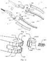
- Embodiment 1 provides an open-close handheld apparatus, which includes a first member 1 and a second member 2.
- the first member 1 includes a first handheld portion 11 and a first clamping portion 12.
- the first handheld portion 11 is located at the bottom part of the first member 1.
- the first clamping portion 12 is located at the top art of the first member 1.
- the second member 2 includes a second handheld portion 21 and a second clamping portion 22.
- the second handheld portion 21 is located at the bottom part of the second member 2.
- the second clamping portion 22 is located at the top part of the second member 2.
- the first clamping portion 12 and the second clamping portion 22 are rotatably and movably connected via a first axle pin 3.
- the first clamping portion 12 and the second clamping portion 22 open and close relative to each other, and the plane in which the open-close path thereof is located is an open-close plane.
- the top end and/or the bottom end of the second clamping portion 22 are oppositely arranged relative to that of the first clamping portion 12.
- the second handheld portion 21 is oppositely arranged relative to the first handheld portion 11.
- the first handheld portion 11 is rotatably connected to the first clamping portion 12.
- the plane in which the rotation path of the first handheld portion 11 is the same as or parallel to the open-close plane.
- a locking arrangement 4 is provided at the joint between the first handheld portion 11 and the first clamping portion 12, used for locking or unlocking the first handheld portion and the first clamping portion 12.
- Another technical feature of the embodiment lies in that, the second handheld portion 21 is rotatably connected to the second clamping portion 22.
- the plane in which the rotation path of the second handheld portion 21 is the same as or parallel to the open-close plane.
- a locking arrangement 4 is provided at the joint between the second handheld portion 21 and the second clamping portion 22, used for locking or unlocking the second handheld portion 21 and the second clamping portion 22.
- the embodiment can have both of the above technical features simultaneously, or can only have one of the two above technical features.
- the locking arrangement 4 of the embodiment is originally in the locked state and can be used normally.
- the locking arrangement 4 is first required to be unlocked, and then the first handheld portion 11 or the second handheld portion 21 is rotated to a desired angle relative to the first clamping portion 12 or the second clamping portion 22, and the locking arrangement 4 is then locked so that the first handheld portion 11 is held fixed relative to the first clamping portion 12, or the second handheld portion 21 is held fixed relative to the second clamping portion 22 for continuous use.
- the angle between the handheld portion and the clamping portion can be adjusted prior to the normal use of this embodiment, however, during use where the two clamping portions are opened to clamp the object to be clamped, the handheld portion and the clamping portion are held in the locked state and the two are fixed relative to each other.
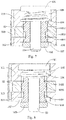
- the locking arrangement 4 includes an extending portion 31, a protruding portion 32 and a second axle pin 33.
- the extending portion 31 is provided at the bottom end of the first clamping portion 12, the cross-section of which is approximately U-shaped, and the extending portion 31 includes a first mounting plate 311, a second mounting plate 312, an assembly groove 313.
- the second mounting plate 312 is oppositely arranged relative to the first mounting plate 311, and the assembly groove 313 is arranged between the first mounting plate 311 and the second mounting plate 312.
- the assembly groove 313 is used for insertion of the protruding portion 32.
- the second mounting plate 312 has shape and size corresponding to those of the first mounting plate 311.
- the protruding portion 32 is provided at the top end of the first handheld portion, and is inserted into the extending portion 31, specifically, inserted into the assembly groove 313.
- the second axle pin 33 is passed through the extending portion 31 and the protruding portion 32 simultaneously.
- the protruding portion 32 is movably connected to the extending portion 31 via the second axle pin 33, so that the first handheld portion 11 is rotatable relative to the first clamping portion 12.
- the first mounting plate 311 includes a first mounting hole 314, and the second mounting plate 312 includes a second mounting hole 315.
- the second mounting hole 315 is oppositely arranged relative to the first mounting hole 314, and has shape and size corresponding to those of the first mounting hole 314.
- the protruding portion 32 includes a third mounting hole 321, which has shape and size corresponding to those of the first mounting hole 314 and the second mounting hole 315.
- the extending portion 31 and the protruding portion 32 of the locking arrangement 4 are rotated relative to each other via the second axle pin 33, so as to drive the relative rotation of the handheld portion and the clamping portion.
- the locking arrangement 4 further includes a first press plate 101, annular sawteeth 102, a spline block 103, a first spring 104 and a nut 105.
- the first press plate 101 is arranged at the top part of the second axle pin 33, the second axle pin 33 is perpendicular to the first press plate 1011, and the outer side wall of the lower end of the second axle pin 33 is provided with external thread for mounting of the nut 105.
- the annular sawteeth 102 are respectively arranged on the inner side walls of the first mounting hole 314, the third mounting hole 321 and the second mounting hole 315.
- the spline block 103 has a cylindrical body with a cylindrical cavity provided therein, sheathed on the outside of the sliding bar 1012.
- Two or more first racks 1031 are evenly distributed around the outer side wall of the spline block 103, and the first racks 1031 are parallel to the sliding bar 1012.
- the cylindrical body of the spline block 103 together with multiple first racks 1031 forms a gear arrangement engaging with the annular sawteeth 102.
- Each of the first racks 1031 from the top part to the bottom part thereof includes successively: a first notch 1032, a first widened tooth 1033, a second notch 1034 and a second widened tooth 1035.
- the length of the first widened tooth 1033 is less than the depth of the third mounting hole 321.
- the length of the second widened tooth 1035 is less than the maximum compression distance of the first spring 104.
- the length of the second notch 1034 is greater than the depth of the third mounting hole 321.
- the first spring 104 is sheathed on the outside of the second axle pin 33, and the top end of the first spring 104 is connected to the bottom part of the first press plate 101, and the bottom end thereof is sheathed on the top part of the spline block 103.
- the spline block 103 slides downward.
- the spline block 103 can be reset by sliding upward to its original position under the action of the first spring 104.
- the nut 105 is sheathed on the lower end of the second axle pin 33.
- the inner side wall of the nut 105 is provided with internal thread.
- the nut 105 corresponds to the external thread of the second axle pin 33.
- the nut 105 is in threaded connection with the lower end of the second axle pin 33, so that the first press plate 101, the spline block 103 and the first spring 104 are combined to be an integral part without separation from each other.
- the first spring 104 in normal state, the first spring 104 is in the relaxed state.
- the plurality of first widened teeth 1033 of the spline block 103 are engaged with the annular sawteeth 102 inside the first mounting hole 314 and the third mounting hole 321.
- the plurality of the second widened teeth 1035 are engaged with the annular sawteeth 102 inside the second mounting hole 321.
- the extending portion 31 and the protruding portion 32 are relatively fixed, the locking arrangement 4 is kept in the locked state, and the first handheld portion 11 is held fixed relative to the first clamping portion 12.
- the first spring 104 is in the pressed state.
- the first widened teeth 1033 are only engaged with the sawteeth inside the third mounting hole 321, and are detached from the sawteeth inside the first mounting hole 314 and the second mounting hole 315.
- the locking arrangement 4 is unlocked to be in the unlocked state.
- the extending portion 31 is rotatable relative to the protruding portion 32 with the second axle pin as the axis of rotation.
- the first handheld portion 11 is rotatable relative to the first clamping portion 12.
- the first spring 104 is in the relaxed state when the first press plate 101 is released as shown in Fig. 7 .
- the first widened teeth 1033 are engaged with the sawteeth inside the first mounting hole 314 and the third mounting hole 321.
- the second widened teeth 1035 are engaged with the sawteeth inside the second mounting hole 321.
- the extending portion 31 is fixed relative to the protruding portion 32, the locking arrangement 4 is in the locked state, and the first handheld portion 11 is held fixed relative to the first clamping portion 12.
- the locking arrangement 4 further includes a press button groove 106 and a nut groove 107.
- the press button groove 106 is arranged on the top part of the first mounting plate 311, and is located above the first mounting hole 314, for placing the first press plate 1011.
- the nut groove 107 is arranged on the bottom part of the second mounting plate 312, and is located below the second mounting hole 315, for placing the nut 105.
- the locking arrangement 4 further includes angle marks 108 and a positioning mark 109.
- the angle marks 108 are provided on the top part of the first mounting plate 311, and are located around the press button groove 106.
- the angle mark 109 is used for marking the rotation angle of the first handheld portion 11 relative to the first clamping portion 12.
- the positioning mark 109 is provided on the top part of the first handheld portion 11, and is adjacent to an end of the protruding portion 32.
- the positioning mark 109 points to any angle value among the angle marks 108.
- the angle marks 108 and the positioning mark 109 are cooperatively used so as to help the user to know in real time and timely adjust the deflection angle of the handheld portion.
- the open-close handheld apparatus includes, but not limited to, clamping means and cutting means.
- the clamping means includes, but not limited to, pliers.
- the cutting means includes, but not limited to, scissors.
- Embodiment 1 provides an open-close handheld apparatus, specifically, a pair of nipper pliers.
- the first clamping portion 12 and the second clamping portion 22 are the clamp head.
- the first handheld portion 11 and the second handheld portion 21 include a handle 110, and may further include a protective sleeve 111 sheathed on the outside of the handle 110.
- One handle is fixedly connected with the clamp head, and the joint between the other handle and the clamp head is rotatable, the rotational direction being consistent with the open-close direction of the clamp head.
- the plane in which the rotation path of the handle 110 is located is the same as or parallel to the open-close plane of the clamp head.
- Embodiment 1 includes two handheld portions, one or two of which is rotatable relative to the clamping portions.
- the user can adjust the angle of one or two handheld portion, so as to adjust the distance and the operation angle between the two handheld portions for facilitating the operation and the use.
- the scheme where both of the angles of the two handheld portion are adjustable has a larger range of adjustable angle and a larger adjustable distance between the two handheld portions and thus wider range of application compared with the scheme where the angle of a single handheld portion is adjustable.
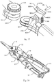
- Embodiment 2 provides another open-close handheld apparatus, specifically, a pair of nipper pliers, which includes most technical schemes as in Embodiment 1, where the locking arrangement 4 includes an extending portion 31, a protruding portion 32 and a second axle pin 33, and the structural function and principle are the same as the embodiment, which will not be described here.
- the open-close handheld apparatus in Embodiment 2, compared with Embodiment 1, has the following distinguishing technical features: the locking arrangement 4 further including a semi-circular gear 201, a stop block 202, a sliding snap button 203 and a second spring 204.
- the semi-circular gear 201 is formed at the terminal end of the first mounting plate 311 and/or the second mounting plate 312.
- the sliding snap button 203 can be snap fitted to the semi-circular gear 201 to function as a position lock. If the other mounting plate is further arranged with a semi-circular gear 201, it cannot be directly engaged with the sliding snap button 203 to function as a lock, yet it can facilitate the assembly and replacement of the components.
- the two handheld portions are both rotatably connected to the clamping portions, then the two handheld portions and the two clamping portions are not integrally designed, instead they are assembled with each other. If only one mounting plate is arranged with a semi-circular gear 201 at its terminal end, then the two handheld portions can only be fixedly mounted to a specific clamping portion, the left and right handheld portions having different shapes and the two being not interchangeable. In order to facilitate maintenance and replacement of the components as well as production and assembly, a semi-circular gear 201 can be arranged at the terminal ends of the first mounting plate 311 and the second mounting plate 312 respectively.
- the stop block 202 protrudes from the upper surface of the handheld portion 11 or the second handheld portion 21, and is adjacent to the protruding portion 32, specifically, the stop block 202 protrudes from the upper surface of the handle.
- the stop block 202 is provided with a U-shaped groove 205 opening toward the semi-circular gear 201, and the bottom part of the U-shaped groove 205 is provided with a spring mounting groove 206 for mounting the second spring 2034.
- the sliding snap button 203 is arranged inside the U-shaped groove 205, and includes a snap button body 2031, a snap button dial knob 2032, a second rack 2033, a second spring mounting shaft 2034.
- the shape of the snap button body 2031 corresponds to the shape of the bottom part of the U-shaped groove 205, and is perpendicular to the protruding portion 32.
- the snap button dial knob 2033 is provided above the snap button body 2031 and protrudes from the upper surface of the first handheld portion 11.
- the second rack 2033 protrudes from the side wall of the snap button body 2031 and facing the side of the semi-circular gear 201.
- the second rack 2033 is perpendicular to the protruding portion 32, and the length thereof corresponds to the snap button body 2031, which can be used to snap fitted to the semi-circular gear 201.
- the height by which the second rack 2033 protrudes from the snap button body 2031 is less than the maximum compression distance of the second spring 2034.
- the second spring mounting shaft 2034 is provided on the side wall of the snap button body 2031, facing the side of the spring mounting groove 206.
- the second spring mounting shaft 2034 is parallel to the protruding portion 32 and is on the same straight line as the spring mounting groove 206, which can be used for mounting the second spring 204.
- the second spring 204 is sheathed on the second spring mounting shaft 2034. One end of the second spring is tangent to the snap button body 2031, and the other end is located inside the spring mounting groove 206.
- the sliding snap button 203 can slide back and forth inside the U-shaped groove 205, and the second spring 204 can help resetting the sliding snap button 203.
- the second spring 204 in the normal state, the second spring 204 is in a relaxed state.
- the second rack 2033 is snapped into the the semi-circular gear 201, the locking arrangement 4 is held in the locked state, and the handheld portion 11/21 can be held fixed relative to the clamping portion 12/22.
- the second spring 204 When the snap button dial knob 2032 is pulled downward, the second spring 204 is in the compressed state.
- the second rack 2033 retracts back to the U-shaped groove 205 and detaches from the semi-circular gear 201, the locking arrangement 4 is unlocked to be adjusted to the unlocked state, and the handheld portion 11/21 can rotate relative to the clamping portion 12/22, that is, the first handheld portion 11 rotates relative to the first clamping portion 12, or the second handheld portion 21 rotates relative to the second clamping portion 22.
- the snap button dial knob 2032 is released, the second spring 204 is again in the relaxed state.
- the second rack 2033 is snap fitted to the semi-circular gear 201 of the first mounting plate 311 and the second mounting plate 312, the locking arrangement 4 is reset to and held in the locked state, and the handheld portion 11/21 can be held fixed relative to the clamping portion 12/22.
- Embodiment 2 includes two handheld portions, one or two of which is rotatable relative to the clamping portion.
- the user can adjust the angle of one or two handheld portion, so as to adjust the distance and the operation angle between the two handheld portions for facilitating the operation and the use.
- the scheme where both of the angles of the two handheld portions are adjustable has a larger range of adjustable angle and a larger adjustable distance between the two handheld portions compared with the scheme where the angle of a single handheld portion is adjustable.
- the components in Embodiment 2 have simpler structure, lower processing cost, and are convenient to use with wider range of application compared with Embodiment 1.
- Embodiment 3 provides another open-close handheld apparatus, specifically, a pair of nipper pliers, which includes most of the technical schemes in Embodiment 1, and the locking arrangement 4 thereof includes an extending portion 31, a protruding portion 32 and a second axle pin 33, and the structural function and principle are the same as the embodiment, which will not be described here.
- the open-close handheld apparatus in Embodiment 3, compared with Embodiment 1, has the following distinguishing technical features: the locking arrangement 4 including a circular gear 301, two oppositely arranged mounting bases 302, a press snap button 303, a third axle pin 304 and a third spring 305.
- the circular gear 301 protrudes from the upper surface of the first mounting plate 311.
- the circular gear 301 is fixed to the first mounting plate 311, or is integrally arranged with the first mounting plate 311.
- the two oppositely arranged mounting bases 302 protrude from the upper surface of the first handheld portion 11 and/or the second handheld portion 21, and is adjacent to the protruding portion 32.
- the two mounting bases 302 are respectively provided with a base axle pin hole 3021, and the two base axle pin holes 3021 lie in the same straight line.
- the press snap button 303 is arranged between the two mounting bases 302, and the press snap button 303 includes a second press plate 3031, a snap engaging portion 3032 and a third rack 3033.
- One end of the second press plate 3031 adjacent to the protruding portion 32 is provided with a press plate axle pin 3034 lying in the same straight line with the two base axle pin holes 3021, and the other end thereof is provided with a third spring mounting shaft 3035 protruding from and perpendicular to the lower surface of the second press plate 3031.
- the snap engaging portion 3032 is provided at one end of the second press plate 3031 adjacent to the protruding portion 32, and the snap engaging portion 3032 forms an angle of 120-160 degrees with the second press plate 3031.
- the third rack 3033 is provided at the top part of the snap engaging portion 3032, and protrudes downward and directly facing the circular gear 301.
- the third axle pin 304 is passed through the press plate axle pin hole 3034 and the two bases axle pin holes 3021 simultaneously.
- the third spring 305 is sheathed on the outside of the third spring mounting shaft 3035.
- One end of the spring 305 is tangent to the lower surface of the second press plate 3031, and the other end thereof is tangent to the upper surfaces of the handheld portions 11, 21.
- the third spring 305 in the normal state, the third spring 305 is in a relaxed state.
- the third rack 3033 is snapped into the circular gear 301, the locking arrangement 4 is held in the locked state, and the handheld portion 11/21 can be held fixed relative to the clamping portion 12/22.
- the third spring 305 When the second press plate 3031 is pressed downward, the third spring 305 is in the compressed state.
- the third rack 3033 is lifted upward and detached from the circular gear 301, the locking arrangement 4 is unlocked to be adjusted into the unlocked state, and the handheld portion 11/21 can rotate relative to the clamping portion 12/22, that is, the first handheld portion 11 rotates relative to the first clamping portion 12, or the second handheld portion 21 rotates relative to the second clamping portion 22.
- the second press plate 3031 is released, the third spring 305 is again in the relaxed state.
- the third rack 3033 is snap fitted to the circular gear 301, the locking arrangement 4 is reset to and held in the locked state, and the handheld portion 11/21 can be held fixed relative to the clamping portion 12/22.
- Embodiment 3 includes two handheld portions, one or two of which is rotatable relative to the clamping portion.
- the user can adjust the angle of one or two handheld portion, so as to adjust the distance and the operation angle between the two handheld portions for facilitating the operation and the use.
- the scheme where both of the angles of the two handheld portions are adjustable has a larger range of adjustable angle and a larger adjustable distance between the two handheld portions compared with the scheme where the angle of a single handheld portion is adjustable.
- the components in Embodiment 3 have simpler structure, lower processing cost, and are convenient to use with wider range of application compared with Embodiment 1.
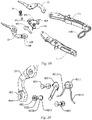
- Embodiment 4 provides another open-close handheld apparatus, specifically, a pair of scissors, which includes part of the technical schemes in Embodiment 1, and the distinguishing technical features thereof compared with Embodiment 1 lie in that: the locking arrangement 4 does not include an extending portion 31, a protruding portion 32 and a second axle pin 33, instead includes an elastic support member 401, the cross-section of which is an inverted V-shape.
- the open-close handheld apparatus of the invention includes but not limited to the clamping means and cutting means, and the cutting means includes but not limited to scissors.
- the locking arrangement 4 further includes a first sliding axle pin 402, a first fixation axle pin 403 and a second fixation axle pin 404.
- the first sliding axle pin 402 is provided at the joint between the upper part of the first handheld portion 11 and the bottom end of the first clamping portion 12.
- the first fixation axle pin 403 is provided at the joint between the top end of the first handheld portion 11 and the top end of the second handheld portion 21.
- the first sliding axle pin 402 is slidably mounted to the first clamping portion 12.
- the second fixation axle pin 404 is provided at the joint between the upper part of the second handheld portion 21 and the bottom end of the second clamping portion 22.
- the elastic support member 401 includes a first support arm 4011, a second support arm 4012 and an arc corner 4013.
- One end of the first support arm 4011 is passed through and fixed to the first handheld portion 11 and the first clamping portion 12, and the other end thereof is connected to the second support arm 4012.
- One end of the second support arm 4012 is passed through and fixed to the second handheld portion 21 and the second clamping portion 22, and the other end thereof is connected to the first support arm 4011.
- the arc corner 4013 is located at the joint between the first support arm 4011 and the second support arm 4012, and the inner side surface of the arc corner 4013 is tangent to the outer surface of the first fixation axle pin 403.
- the elastic support member 401 can assist the separation of the two clamping portions to be easily opened.
- a fixation ring 408 can further be arranged at the bottom part of the handheld portion, for fixing the relative position of the two handheld portions when the open-close handheld apparatus is in the closed state.
- a fixation axle pin is arranged at the joint between the handheld portion and the clamping portion, so that the handheld portion and the clamping portion cannot rotate relative to each other, and once the rotation occurs, it will result in separation of the two clamping portions from each other (the scissors in the open state).
- a sliding axle pin is arranged at the joint between the handheld portion and the clamping portion, so that the handheld portion and the clamping portion can rotate relative to each other within a certain range of angle.
- the locking arrangement 4 includes a first sliding axle pin 402, a first fixation axle pin 403 and a second sliding axle pin (not shown).
- the second sliding axle pin has the same structure as the first sliding axle pin 402.
- the first sliding axle pin 402 is provided at the joint between the upper part of the first handheld portion 11 and the bottom end of the first clamping portion 12.
- the first fixation axle pin 403 is provided at the joint between the top end of the first handheld portion 11 and the top end of the second handheld portion 21.
- the second sliding axle pin is provided at the joint between the upper part of the second handheld portion 21 and the bottom end of the second clamping portion 22.
- the first sliding axle pin 403 is slidably mounted to the first clamping portion 12.
- the second sliding axle pin is slidably mounted to the second clamping portion 22.
- one sliding axle pin is respectively arranged at the joints between the two sets of handheld portions and the clamping portions, so that the two sets of handheld portions and the clamping portions can rotate relative to each other within a certain range of angle, and the adjustment range thereof is wider compared with that in the former embodiment.
- the first sliding axle pin 402 or the second sliding axle pin successively includes a third press plate 4021, a thin shaft portion 4022, a thick shaft portion 4023 and an axle pin base 4024 that are connected with each other.
- the third press plate 4021 and the axle pin base 4024 protrude from the outside of the first handheld portion 11 or the second handheld portion 21.
- the locking arrangement 4 further includes more than two location holes 405 that are communicated with each other and at least one sliding opening 406. More than two location holes 405 that are communicated with each other are provided at the bottom end of the first clamping portion 12 and/or the second clamping portion 22.
- the first sliding axle pin 402 and/or the second sliding axle pin 404 are/is slidably mounted into the location holes 405. Each sliding opening 406 is provided at the communication location between two adjacent location holes.
- the locking arrangement 4 further includes one or two interlocking plate 407, one end of which is connected to the first fixation axle pin 403, and the other end of which is connected to the axle pin base(s) 4024 of the first sliding axle pin 402 and/or the second sliding axle pin 404.
- the thick shaft portion 4023 In the normal state, the thick shaft portion 4023 is located inside one location hole 405, and the locking arrangement 4 is in the locked state.
- the thick shaft portion 4023 enables the handheld portions 11, 21 to be fixed relative to the clamping portions 12, 22 since the diameter of the thick shaft portion 4023 corresponds to that of the location hole 405, and the locking arrangement 4 is in the locked state.
- the third press plate 4021 When the third press plate 4021 is pressed downward, the interlocking plate 407 is deformed, and the thick shaft portion 4023 detaches from one of the location holes 405.
- the locking arrangement 4 is unlocked to be adjusted into the unlocked state.
- the thin shaft portion 4022 is passed through a sliding opening 406 between two location holes 405 and slides to a next location hole 405 since the diameter of the thin shaft portion 4022 corresponds to the width of the sliding opening 406.
- the interlocking plate 407 recovers from deformation, the thick shaft portion 4023 enters and is snapped into a next location hole 405, and the locking arrangement 4 is again in the locked state.
- Embodiment 4 includes two handheld portions, and one or two of the handheld portions can rotate relative to the clamping portion when the two clamping portions are held in a relatively stationary state, so that the angle of one or two handles of the scissors can be adjusted.
- the user can adjust the angle of one or two handheld portion, so as to adjust the distance and the operation angle between the two handheld portions to be adapted to the hand shape and using habit of the user, facilitating the operation and use.
- the scheme where both of the angles of the two handheld portions are adjustable has a larger range of adjustable angle and a larger adjustable distance between the two handheld portions compared with the scheme where the angle of a single handheld portion is adjustable.
- Embodiment 5 provides a method of adjustment of the angle between the handheld portions of another open-close handheld apparatus according to any one in Embodiments 1 to 4, the method specifically including the following steps:
- the angle adjustment method in Steps S101 to S103 are adopted to adjust the angle of the handheld portion at one side thereof so as to change the angle between the handheld portion and the clamping portion at the one side and to change the distance between two handheld portions, so as to adapt to the user's habit of using tools, and the user's operation can be more effort saving and the open-close handheld apparatus is preferably adapted to different situations.
- Embodiment 5 further provides another method of adjustment of the angle between the handheld portions of the open-close handheld apparatus according to any one in Embodiments 1 to 4, the method specifically including the following steps:
- the angle adjustment method in Steps S201 to S206 is adopted to adjust the angle of the handheld portion at both sides thereof so as to change the angle between the handheld portion and the clamping portion at the both sides and to change the distance between two handheld portions, so as to adapt to the user's habit of using tools, and the user's operation can be more effort saving and the open-close handheld apparatus is preferably adapted to different operation conditions.
- the advantage of the invention lies in that an open-close handheld apparatus and a method of adjustment of the angle between the handheld portions thereof are provided, and the user can autonomously adjust the relative angle between the handheld portion and the clamping portion of the handheld tool in the open-close direction according to the size of the use's hand and the habit of exerting force and lock the handheld tool, so that the user can operate and use the handheld tool in an angle which is most familiar to the users and most convenient to use.
- the angle between the clamping portions therefore is relatively large, yet the angle between the handheld portions can then be adjusted to a proper position so that the distance between the two ends of the two opened handheld portions is relatively small, and the user can exert force with a single hand to the ends of the two handheld portions so as to complete the operation smoothly, which is more effort saving compared with normal open-close apparatus.
Landscapes
- Engineering & Computer Science (AREA)
- Mechanical Engineering (AREA)
- Clamps And Clips (AREA)
- Scissors And Nippers (AREA)
- Gripping Jigs, Holding Jigs, And Positioning Jigs (AREA)
- Telephone Set Structure (AREA)
Applications Claiming Priority (1)
| Application Number | Priority Date | Filing Date | Title |
|---|---|---|---|
| PCT/CN2016/109938 WO2018107399A1 (zh) | 2016-12-14 | 2016-12-14 | 一种张合式手持装置及其手持部角度调节方法 |
Publications (3)
| Publication Number | Publication Date |
|---|---|
| EP3556514A1 true EP3556514A1 (de) | 2019-10-23 |
| EP3556514A4 EP3556514A4 (de) | 2020-09-02 |
| EP3556514B1 EP3556514B1 (de) | 2021-07-21 |
Family
ID=62557786
Family Applications (1)
| Application Number | Title | Priority Date | Filing Date |
|---|---|---|---|
| EP16923931.6A Active EP3556514B1 (de) | 2016-12-14 | 2016-12-14 | Öffnende und schliessende handhaltbare vorrichtung und winkelverstellverfahren für handhaltbaren abschnitt davon |
Country Status (6)
| Country | Link |
|---|---|
| US (1) | US11628543B2 (de) |
| EP (1) | EP3556514B1 (de) |
| JP (1) | JP7049341B2 (de) |
| AU (1) | AU2016432620A1 (de) |
| CA (1) | CA3047030A1 (de) |
| WO (1) | WO2018107399A1 (de) |
Families Citing this family (7)
| Publication number | Priority date | Publication date | Assignee | Title |
|---|---|---|---|---|
| US11583979B2 (en) | 2017-04-28 | 2023-02-21 | Hangzhou Great Star Industrial Co., Ltd. | Open-close device |
| US11745326B2 (en) * | 2018-03-30 | 2023-09-05 | Milwaukee Electric Tool Corporation | Bolt cutter |
| CN112135704B (zh) | 2018-03-30 | 2023-08-25 | 米沃奇电动工具公司 | 螺栓切割器 |
| IL275022B (en) * | 2020-05-31 | 2021-06-30 | Namdar Shay | A pliers-like tool with a rotating head |
| CN112201971B (zh) * | 2020-09-11 | 2024-05-24 | 国网宁夏电力有限公司检修公司 | 一种可调角度的接地操作杆 |
| US12384062B2 (en) * | 2021-09-29 | 2025-08-12 | Contraption Collection LLC | Locking mechanism for folding devices |
| CN120079604B (zh) * | 2025-04-09 | 2025-10-10 | 彤诺电子鄂州有限公司 | 一种液晶显示屏背光模组质量检测装置及检测方法 |
Family Cites Families (19)
| Publication number | Priority date | Publication date | Assignee | Title |
|---|---|---|---|---|
| JPS5320793Y2 (de) * | 1975-04-08 | 1978-05-31 | ||
| DE2941616C2 (de) * | 1979-10-13 | 1983-12-08 | Hans 5630 Remscheid Mesenhöller | Knarre mit am Griffstiel angelenktem Arbeitskopf |
| EP0728061B1 (de) | 1993-11-09 | 1998-02-25 | "JAGUAR" STAHLWARENFABRIK GMBH & CO. KG | Schere, insbesondere friseurschere |
| JPH10179950A (ja) * | 1996-12-19 | 1998-07-07 | Fuitsuto Kogyo Kk | 道 具 |
| US5974670A (en) * | 1997-10-30 | 1999-11-02 | Hsieh; Chih-Ching | Multipurpose tool |
| DE10113012C1 (de) * | 2001-03-17 | 2002-08-14 | Vulkan Lokring Gmbh & Co Kg | Handzange |
| US6662690B1 (en) | 2002-06-20 | 2003-12-16 | Lisle Corporation | Pliers for clamping a hose or tube |
| KR100492958B1 (ko) | 2002-09-10 | 2005-06-07 | 삼성전자주식회사 | 무선 고속 데이터 시스템에서 공중망과 사설망의 공통사용 방법 및 시스템 |
| US20060230886A1 (en) * | 2004-08-04 | 2006-10-19 | Chih-Ching Hsien | Pliers having pivotal handles |
| US20060090613A1 (en) * | 2004-11-02 | 2006-05-04 | Chih-Ching Hsieh | Pivotal retaining device of hand tool |
| FR2911295B1 (fr) * | 2007-01-11 | 2009-04-17 | Bost Garnache Ind Soc Par Acti | Pince multiprise entrepassee a reglage fin |
| DE202008008012U1 (de) | 2008-01-31 | 2009-06-18 | Weidmüller Interface GmbH & Co. KG | Zangengriff |
| DE202009005131U1 (de) * | 2009-08-12 | 2009-11-19 | Su, Cheng-Wei | Vorrichtung zur Steuerung der Drehbewegung eines Werkzeugs |
| TWI369273B (en) * | 2010-03-09 | 2012-08-01 | Kabo Tool Co | Structure for positioning pivot, hand tool and pliers |
| CN102554839B (zh) * | 2010-12-27 | 2014-04-30 | 英发企业股份有限公司 | 快速操作的扳手 |
| JP2013220522A (ja) | 2012-04-19 | 2013-10-28 | Toho Koki Kk | 切断工具 |
| JP3184736U (ja) | 2013-05-01 | 2013-07-11 | 株式会社バシーン・インターナショナル | 鋏 |
| NL2011891C2 (nl) | 2013-12-04 | 2015-06-08 | Robbie Haak | Verstelbaar handgereedschap. |
| CN208231843U (zh) * | 2015-12-10 | 2018-12-14 | 米沃奇电动工具公司 | 螺栓切割工具 |
-
2016
- 2016-12-14 US US16/469,563 patent/US11628543B2/en active Active
- 2016-12-14 CA CA3047030A patent/CA3047030A1/en not_active Abandoned
- 2016-12-14 EP EP16923931.6A patent/EP3556514B1/de active Active
- 2016-12-14 WO PCT/CN2016/109938 patent/WO2018107399A1/zh not_active Ceased
- 2016-12-14 JP JP2019531986A patent/JP7049341B2/ja active Active
- 2016-12-14 AU AU2016432620A patent/AU2016432620A1/en not_active Abandoned
Also Published As
| Publication number | Publication date |
|---|---|
| JP2020513338A (ja) | 2020-05-14 |
| EP3556514A4 (de) | 2020-09-02 |
| JP7049341B2 (ja) | 2022-04-06 |
| US20190389037A1 (en) | 2019-12-26 |
| AU2016432620A1 (en) | 2019-07-25 |
| WO2018107399A1 (zh) | 2018-06-21 |
| US11628543B2 (en) | 2023-04-18 |
| EP3556514B1 (de) | 2021-07-21 |
| CA3047030A1 (en) | 2018-06-21 |
Similar Documents
| Publication | Publication Date | Title |
|---|---|---|
| EP3556514A1 (de) | Öffnende und schliessende handhaltbare vorrichtung und winkelverstellverfahren für handhaltbaren abschnitt davon | |
| CN206550893U (zh) | 一种张合式手持装置 | |
| US5150488A (en) | Multifunctional tool | |
| US7735399B2 (en) | Clamping and cutting apparatus with adjustable head | |
| AU2017386860B2 (en) | Blade-replaceable cutting tool | |
| US9630301B2 (en) | Compact gas cylinder valve ratchet driver tool | |
| BR112017027705B1 (pt) | Trocador rotativo | |
| US20150165597A1 (en) | Multiple-function hand tool | |
| CN108214339B (zh) | 一种张合式手持装置及其手持部角度调节方法 | |
| US20160214246A1 (en) | Pair of circlip pliers | |
| CN207358903U (zh) | 一种张合装置 | |
| US20250196379A1 (en) | Blade-replaceable cutting tool | |
| CN107605891B (zh) | 一种带伸缩杆的电动工具 | |
| CN207522416U (zh) | 一种快速夹紧装置 | |
| CN207578329U (zh) | 一种多功能手持工具 | |
| CN206605394U (zh) | 一种张合装置 | |
| US11583979B2 (en) | Open-close device | |
| CN210389000U (zh) | 移动机构和具有该移动机构的手动工具 | |
| US10933513B2 (en) | Opening-closing device | |
| CN102938989A (zh) | 拉带定位结构 | |
| EP3766147B1 (de) | Crimpwerkzeug | |
| CN108789197A (zh) | 一种张合装置 | |
| US20200391356A1 (en) | Open-close handheld apparatus and method of adjustment of angle between handheld portions thereof | |
| US20070214607A1 (en) | Bendable handle | |
| KR100417981B1 (ko) | 유니버셜 스크라이버 |
Legal Events
| Date | Code | Title | Description |
|---|---|---|---|
| STAA | Information on the status of an ep patent application or granted ep patent |
Free format text: STATUS: THE INTERNATIONAL PUBLICATION HAS BEEN MADE |
|
| PUAI | Public reference made under article 153(3) epc to a published international application that has entered the european phase |
Free format text: ORIGINAL CODE: 0009012 |
|
| STAA | Information on the status of an ep patent application or granted ep patent |
Free format text: STATUS: REQUEST FOR EXAMINATION WAS MADE |
|
| 17P | Request for examination filed |
Effective date: 20190712 |
|
| AK | Designated contracting states |
Kind code of ref document: A1 Designated state(s): AL AT BE BG CH CY CZ DE DK EE ES FI FR GB GR HR HU IE IS IT LI LT LU LV MC MK MT NL NO PL PT RO RS SE SI SK SM TR |
|
| AX | Request for extension of the european patent |
Extension state: BA ME |
|
| DAV | Request for validation of the european patent (deleted) | ||
| DAX | Request for extension of the european patent (deleted) | ||
| A4 | Supplementary search report drawn up and despatched |
Effective date: 20200803 |
|
| RIC1 | Information provided on ipc code assigned before grant |
Ipc: B25B 7/12 20060101AFI20200728BHEP Ipc: B25G 1/06 20060101ALI20200728BHEP Ipc: B25B 7/18 20060101ALI20200728BHEP Ipc: B25B 7/14 20060101ALI20200728BHEP Ipc: B25B 7/08 20060101ALI20200728BHEP |
|
| RIC1 | Information provided on ipc code assigned before grant |
Ipc: B25B 7/12 20060101AFI20210310BHEP Ipc: B25G 1/06 20060101ALI20210310BHEP Ipc: B25B 7/08 20060101ALI20210310BHEP Ipc: B25B 7/18 20060101ALI20210310BHEP Ipc: B25B 7/14 20060101ALI20210310BHEP |
|
| GRAP | Despatch of communication of intention to grant a patent |
Free format text: ORIGINAL CODE: EPIDOSNIGR1 |
|
| STAA | Information on the status of an ep patent application or granted ep patent |
Free format text: STATUS: GRANT OF PATENT IS INTENDED |
|
| INTG | Intention to grant announced |
Effective date: 20210426 |
|
| GRAS | Grant fee paid |
Free format text: ORIGINAL CODE: EPIDOSNIGR3 |
|
| GRAA | (expected) grant |
Free format text: ORIGINAL CODE: 0009210 |
|
| STAA | Information on the status of an ep patent application or granted ep patent |
Free format text: STATUS: THE PATENT HAS BEEN GRANTED |
|
| AK | Designated contracting states |
Kind code of ref document: B1 Designated state(s): AL AT BE BG CH CY CZ DE DK EE ES FI FR GB GR HR HU IE IS IT LI LT LU LV MC MK MT NL NO PL PT RO RS SE SI SK SM TR |
|
| REG | Reference to a national code |
Ref country code: GB Ref legal event code: FG4D |
|
| REG | Reference to a national code |
Ref country code: CH Ref legal event code: EP |
|
| REG | Reference to a national code |
Ref country code: DE Ref legal event code: R096 Ref document number: 602016061146 Country of ref document: DE |
|
| REG | Reference to a national code |
Ref country code: AT Ref legal event code: REF Ref document number: 1412166 Country of ref document: AT Kind code of ref document: T Effective date: 20210815 |
|
| REG | Reference to a national code |
Ref country code: IE Ref legal event code: FG4D |
|
| REG | Reference to a national code |
Ref country code: LT Ref legal event code: MG9D |
|
| REG | Reference to a national code |
Ref country code: NL Ref legal event code: MP Effective date: 20210721 |
|
| REG | Reference to a national code |
Ref country code: AT Ref legal event code: MK05 Ref document number: 1412166 Country of ref document: AT Kind code of ref document: T Effective date: 20210721 |
|
| PG25 | Lapsed in a contracting state [announced via postgrant information from national office to epo] |
Ref country code: PT Free format text: LAPSE BECAUSE OF FAILURE TO SUBMIT A TRANSLATION OF THE DESCRIPTION OR TO PAY THE FEE WITHIN THE PRESCRIBED TIME-LIMIT Effective date: 20211122 Ref country code: NO Free format text: LAPSE BECAUSE OF FAILURE TO SUBMIT A TRANSLATION OF THE DESCRIPTION OR TO PAY THE FEE WITHIN THE PRESCRIBED TIME-LIMIT Effective date: 20211021 Ref country code: NL Free format text: LAPSE BECAUSE OF FAILURE TO SUBMIT A TRANSLATION OF THE DESCRIPTION OR TO PAY THE FEE WITHIN THE PRESCRIBED TIME-LIMIT Effective date: 20210721 Ref country code: ES Free format text: LAPSE BECAUSE OF FAILURE TO SUBMIT A TRANSLATION OF THE DESCRIPTION OR TO PAY THE FEE WITHIN THE PRESCRIBED TIME-LIMIT Effective date: 20210721 Ref country code: FI Free format text: LAPSE BECAUSE OF FAILURE TO SUBMIT A TRANSLATION OF THE DESCRIPTION OR TO PAY THE FEE WITHIN THE PRESCRIBED TIME-LIMIT Effective date: 20210721 Ref country code: HR Free format text: LAPSE BECAUSE OF FAILURE TO SUBMIT A TRANSLATION OF THE DESCRIPTION OR TO PAY THE FEE WITHIN THE PRESCRIBED TIME-LIMIT Effective date: 20210721 Ref country code: BG Free format text: LAPSE BECAUSE OF FAILURE TO SUBMIT A TRANSLATION OF THE DESCRIPTION OR TO PAY THE FEE WITHIN THE PRESCRIBED TIME-LIMIT Effective date: 20211021 Ref country code: AT Free format text: LAPSE BECAUSE OF FAILURE TO SUBMIT A TRANSLATION OF THE DESCRIPTION OR TO PAY THE FEE WITHIN THE PRESCRIBED TIME-LIMIT Effective date: 20210721 Ref country code: LT Free format text: LAPSE BECAUSE OF FAILURE TO SUBMIT A TRANSLATION OF THE DESCRIPTION OR TO PAY THE FEE WITHIN THE PRESCRIBED TIME-LIMIT Effective date: 20210721 Ref country code: SE Free format text: LAPSE BECAUSE OF FAILURE TO SUBMIT A TRANSLATION OF THE DESCRIPTION OR TO PAY THE FEE WITHIN THE PRESCRIBED TIME-LIMIT Effective date: 20210721 Ref country code: RS Free format text: LAPSE BECAUSE OF FAILURE TO SUBMIT A TRANSLATION OF THE DESCRIPTION OR TO PAY THE FEE WITHIN THE PRESCRIBED TIME-LIMIT Effective date: 20210721 |
|
| PG25 | Lapsed in a contracting state [announced via postgrant information from national office to epo] |
Ref country code: PL Free format text: LAPSE BECAUSE OF FAILURE TO SUBMIT A TRANSLATION OF THE DESCRIPTION OR TO PAY THE FEE WITHIN THE PRESCRIBED TIME-LIMIT Effective date: 20210721 Ref country code: LV Free format text: LAPSE BECAUSE OF FAILURE TO SUBMIT A TRANSLATION OF THE DESCRIPTION OR TO PAY THE FEE WITHIN THE PRESCRIBED TIME-LIMIT Effective date: 20210721 Ref country code: GR Free format text: LAPSE BECAUSE OF FAILURE TO SUBMIT A TRANSLATION OF THE DESCRIPTION OR TO PAY THE FEE WITHIN THE PRESCRIBED TIME-LIMIT Effective date: 20211022 |
|
| REG | Reference to a national code |
Ref country code: DE Ref legal event code: R097 Ref document number: 602016061146 Country of ref document: DE |
|
| PG25 | Lapsed in a contracting state [announced via postgrant information from national office to epo] |
Ref country code: DK Free format text: LAPSE BECAUSE OF FAILURE TO SUBMIT A TRANSLATION OF THE DESCRIPTION OR TO PAY THE FEE WITHIN THE PRESCRIBED TIME-LIMIT Effective date: 20210721 |
|
| PLBE | No opposition filed within time limit |
Free format text: ORIGINAL CODE: 0009261 |
|
| STAA | Information on the status of an ep patent application or granted ep patent |
Free format text: STATUS: NO OPPOSITION FILED WITHIN TIME LIMIT |
|
| PG25 | Lapsed in a contracting state [announced via postgrant information from national office to epo] |
Ref country code: SM Free format text: LAPSE BECAUSE OF FAILURE TO SUBMIT A TRANSLATION OF THE DESCRIPTION OR TO PAY THE FEE WITHIN THE PRESCRIBED TIME-LIMIT Effective date: 20210721 Ref country code: SK Free format text: LAPSE BECAUSE OF FAILURE TO SUBMIT A TRANSLATION OF THE DESCRIPTION OR TO PAY THE FEE WITHIN THE PRESCRIBED TIME-LIMIT Effective date: 20210721 Ref country code: RO Free format text: LAPSE BECAUSE OF FAILURE TO SUBMIT A TRANSLATION OF THE DESCRIPTION OR TO PAY THE FEE WITHIN THE PRESCRIBED TIME-LIMIT Effective date: 20210721 Ref country code: EE Free format text: LAPSE BECAUSE OF FAILURE TO SUBMIT A TRANSLATION OF THE DESCRIPTION OR TO PAY THE FEE WITHIN THE PRESCRIBED TIME-LIMIT Effective date: 20210721 Ref country code: CZ Free format text: LAPSE BECAUSE OF FAILURE TO SUBMIT A TRANSLATION OF THE DESCRIPTION OR TO PAY THE FEE WITHIN THE PRESCRIBED TIME-LIMIT Effective date: 20210721 Ref country code: AL Free format text: LAPSE BECAUSE OF FAILURE TO SUBMIT A TRANSLATION OF THE DESCRIPTION OR TO PAY THE FEE WITHIN THE PRESCRIBED TIME-LIMIT Effective date: 20210721 |
|
| 26N | No opposition filed |
Effective date: 20220422 |
|
| PG25 | Lapsed in a contracting state [announced via postgrant information from national office to epo] |
Ref country code: MC Free format text: LAPSE BECAUSE OF FAILURE TO SUBMIT A TRANSLATION OF THE DESCRIPTION OR TO PAY THE FEE WITHIN THE PRESCRIBED TIME-LIMIT Effective date: 20210721 Ref country code: IT Free format text: LAPSE BECAUSE OF FAILURE TO SUBMIT A TRANSLATION OF THE DESCRIPTION OR TO PAY THE FEE WITHIN THE PRESCRIBED TIME-LIMIT Effective date: 20210721 |
|
| REG | Reference to a national code |
Ref country code: CH Ref legal event code: PL |
|
| REG | Reference to a national code |
Ref country code: BE Ref legal event code: MM Effective date: 20211231 |
|
| PG25 | Lapsed in a contracting state [announced via postgrant information from national office to epo] |
Ref country code: LU Free format text: LAPSE BECAUSE OF NON-PAYMENT OF DUE FEES Effective date: 20211214 Ref country code: IE Free format text: LAPSE BECAUSE OF NON-PAYMENT OF DUE FEES Effective date: 20211214 |
|
| PG25 | Lapsed in a contracting state [announced via postgrant information from national office to epo] |
Ref country code: BE Free format text: LAPSE BECAUSE OF NON-PAYMENT OF DUE FEES Effective date: 20211231 |
|
| PG25 | Lapsed in a contracting state [announced via postgrant information from national office to epo] |
Ref country code: LI Free format text: LAPSE BECAUSE OF NON-PAYMENT OF DUE FEES Effective date: 20211231 Ref country code: CH Free format text: LAPSE BECAUSE OF NON-PAYMENT OF DUE FEES Effective date: 20211231 |
|
| PG25 | Lapsed in a contracting state [announced via postgrant information from national office to epo] |
Ref country code: CY Free format text: LAPSE BECAUSE OF FAILURE TO SUBMIT A TRANSLATION OF THE DESCRIPTION OR TO PAY THE FEE WITHIN THE PRESCRIBED TIME-LIMIT Effective date: 20210721 |
|
| PG25 | Lapsed in a contracting state [announced via postgrant information from national office to epo] |
Ref country code: HU Free format text: LAPSE BECAUSE OF FAILURE TO SUBMIT A TRANSLATION OF THE DESCRIPTION OR TO PAY THE FEE WITHIN THE PRESCRIBED TIME-LIMIT; INVALID AB INITIO Effective date: 20161214 |
|
| PG25 | Lapsed in a contracting state [announced via postgrant information from national office to epo] |
Ref country code: MK Free format text: LAPSE BECAUSE OF FAILURE TO SUBMIT A TRANSLATION OF THE DESCRIPTION OR TO PAY THE FEE WITHIN THE PRESCRIBED TIME-LIMIT Effective date: 20210721 |
|
| PG25 | Lapsed in a contracting state [announced via postgrant information from national office to epo] |
Ref country code: MT Free format text: LAPSE BECAUSE OF FAILURE TO SUBMIT A TRANSLATION OF THE DESCRIPTION OR TO PAY THE FEE WITHIN THE PRESCRIBED TIME-LIMIT Effective date: 20210721 |
|
| PG25 | Lapsed in a contracting state [announced via postgrant information from national office to epo] |
Ref country code: TR Free format text: LAPSE BECAUSE OF FAILURE TO SUBMIT A TRANSLATION OF THE DESCRIPTION OR TO PAY THE FEE WITHIN THE PRESCRIBED TIME-LIMIT Effective date: 20210721 |
|
| PGFP | Annual fee paid to national office [announced via postgrant information from national office to epo] |
Ref country code: GB Payment date: 20251229 Year of fee payment: 10 |
|
| PGFP | Annual fee paid to national office [announced via postgrant information from national office to epo] |
Ref country code: FR Payment date: 20251230 Year of fee payment: 10 |
|
| PGFP | Annual fee paid to national office [announced via postgrant information from national office to epo] |
Ref country code: DE Payment date: 20251231 Year of fee payment: 10 |