EP3766147B1 - Crimpwerkzeug - Google Patents
Crimpwerkzeug Download PDFInfo
- Publication number
- EP3766147B1 EP3766147B1 EP19768390.7A EP19768390A EP3766147B1 EP 3766147 B1 EP3766147 B1 EP 3766147B1 EP 19768390 A EP19768390 A EP 19768390A EP 3766147 B1 EP3766147 B1 EP 3766147B1
- Authority
- EP
- European Patent Office
- Prior art keywords
- jaw
- crimping tool
- linkage
- coupled
- teeth
- Prior art date
- Legal status (The legal status is an assumption and is not a legal conclusion. Google has not performed a legal analysis and makes no representation as to the accuracy of the status listed.)
- Active
Links
Images




Classifications
-
- B—PERFORMING OPERATIONS; TRANSPORTING
- B21—MECHANICAL METAL-WORKING WITHOUT ESSENTIALLY REMOVING MATERIAL; PUNCHING METAL
- B21D—WORKING OR PROCESSING OF SHEET METAL OR METAL TUBES, RODS OR PROFILES WITHOUT ESSENTIALLY REMOVING MATERIAL; PUNCHING METAL
- B21D39/00—Application of procedures in order to connect objects or parts, e.g. coating with sheet metal otherwise than by plating; Tube expanders
- B21D39/04—Application of procedures in order to connect objects or parts, e.g. coating with sheet metal otherwise than by plating; Tube expanders of tubes with tubes; of tubes with rods
- B21D39/048—Application of procedures in order to connect objects or parts, e.g. coating with sheet metal otherwise than by plating; Tube expanders of tubes with tubes; of tubes with rods using presses for radially crimping tubular elements
-
- H—ELECTRICITY
- H01—ELECTRIC ELEMENTS
- H01R—ELECTRICALLY-CONDUCTIVE CONNECTIONS; STRUCTURAL ASSOCIATIONS OF A PLURALITY OF MUTUALLY-INSULATED ELECTRICAL CONNECTING ELEMENTS; COUPLING DEVICES; CURRENT COLLECTORS
- H01R43/00—Apparatus or processes specially adapted for manufacturing, assembling, maintaining, or repairing of line connectors or current collectors or for joining electric conductors
- H01R43/04—Apparatus or processes specially adapted for manufacturing, assembling, maintaining, or repairing of line connectors or current collectors or for joining electric conductors for forming connections by deformation, e.g. crimping tool
- H01R43/042—Hand tools for crimping
-
- B—PERFORMING OPERATIONS; TRANSPORTING
- B25—HAND TOOLS; PORTABLE POWER-DRIVEN TOOLS; MANIPULATORS
- B25B—TOOLS OR BENCH DEVICES NOT OTHERWISE PROVIDED FOR, FOR FASTENING, CONNECTING, DISENGAGING, OR HOLDING
- B25B27/00—Hand tools, specially adapted for fitting together or separating parts or objects whether or not involving some deformation, not otherwise provided for
- B25B27/02—Hand tools, specially adapted for fitting together or separating parts or objects whether or not involving some deformation, not otherwise provided for for connecting objects by press fit or detaching same
- B25B27/10—Hand tools, specially adapted for fitting together or separating parts or objects whether or not involving some deformation, not otherwise provided for for connecting objects by press fit or detaching same inserting fittings into hoses
-
- B—PERFORMING OPERATIONS; TRANSPORTING
- B25—HAND TOOLS; PORTABLE POWER-DRIVEN TOOLS; MANIPULATORS
- B25B—TOOLS OR BENCH DEVICES NOT OTHERWISE PROVIDED FOR, FOR FASTENING, CONNECTING, DISENGAGING, OR HOLDING
- B25B27/00—Hand tools, specially adapted for fitting together or separating parts or objects whether or not involving some deformation, not otherwise provided for
- B25B27/14—Hand tools, specially adapted for fitting together or separating parts or objects whether or not involving some deformation, not otherwise provided for for assembling objects other than by press fit or detaching same
- B25B27/146—Clip clamping hand tools
-
- B—PERFORMING OPERATIONS; TRANSPORTING
- B25—HAND TOOLS; PORTABLE POWER-DRIVEN TOOLS; MANIPULATORS
- B25G—HANDLES FOR HAND IMPLEMENTS
- B25G1/00—Handle constructions
- B25G1/06—Handle constructions reversible or adjustable for position
- B25G1/063—Handle constructions reversible or adjustable for position for screwdrivers, wrenches or spanners
-
- B—PERFORMING OPERATIONS; TRANSPORTING
- B23—MACHINE TOOLS; METAL-WORKING NOT OTHERWISE PROVIDED FOR
- B23P—METAL-WORKING NOT OTHERWISE PROVIDED FOR; COMBINED OPERATIONS; UNIVERSAL MACHINE TOOLS
- B23P11/00—Connecting or disconnecting metal parts or objects by metal-working techniques not otherwise provided for
-
- B—PERFORMING OPERATIONS; TRANSPORTING
- B23—MACHINE TOOLS; METAL-WORKING NOT OTHERWISE PROVIDED FOR
- B23P—METAL-WORKING NOT OTHERWISE PROVIDED FOR; COMBINED OPERATIONS; UNIVERSAL MACHINE TOOLS
- B23P11/00—Connecting or disconnecting metal parts or objects by metal-working techniques not otherwise provided for
- B23P11/005—Connecting or disconnecting metal parts or objects by metal-working techniques not otherwise provided for by expanding or crimping
-
- B—PERFORMING OPERATIONS; TRANSPORTING
- B23—MACHINE TOOLS; METAL-WORKING NOT OTHERWISE PROVIDED FOR
- B23P—METAL-WORKING NOT OTHERWISE PROVIDED FOR; COMBINED OPERATIONS; UNIVERSAL MACHINE TOOLS
- B23P13/00—Making metal objects by operations essentially involving machining but not covered by a single other subclass
-
- B—PERFORMING OPERATIONS; TRANSPORTING
- B25—HAND TOOLS; PORTABLE POWER-DRIVEN TOOLS; MANIPULATORS
- B25B—TOOLS OR BENCH DEVICES NOT OTHERWISE PROVIDED FOR, FOR FASTENING, CONNECTING, DISENGAGING, OR HOLDING
- B25B17/00—Hand-driven gear-operated wrenches or screwdrivers
-
- B—PERFORMING OPERATIONS; TRANSPORTING
- B25—HAND TOOLS; PORTABLE POWER-DRIVEN TOOLS; MANIPULATORS
- B25B—TOOLS OR BENCH DEVICES NOT OTHERWISE PROVIDED FOR, FOR FASTENING, CONNECTING, DISENGAGING, OR HOLDING
- B25B7/00—Pliers; Other hand-held gripping tools with jaws on pivoted limbs; Details applicable generally to pivoted-limb hand tools
-
- B—PERFORMING OPERATIONS; TRANSPORTING
- B25—HAND TOOLS; PORTABLE POWER-DRIVEN TOOLS; MANIPULATORS
- B25B—TOOLS OR BENCH DEVICES NOT OTHERWISE PROVIDED FOR, FOR FASTENING, CONNECTING, DISENGAGING, OR HOLDING
- B25B7/00—Pliers; Other hand-held gripping tools with jaws on pivoted limbs; Details applicable generally to pivoted-limb hand tools
- B25B7/22—Pliers provided with auxiliary tool elements, e.g. cutting edges, nail extractors
-
- Y—GENERAL TAGGING OF NEW TECHNOLOGICAL DEVELOPMENTS; GENERAL TAGGING OF CROSS-SECTIONAL TECHNOLOGIES SPANNING OVER SEVERAL SECTIONS OF THE IPC; TECHNICAL SUBJECTS COVERED BY FORMER USPC CROSS-REFERENCE ART COLLECTIONS [XRACs] AND DIGESTS
- Y10—TECHNICAL SUBJECTS COVERED BY FORMER USPC
- Y10T—TECHNICAL SUBJECTS COVERED BY FORMER US CLASSIFICATION
- Y10T29/00—Metal working
- Y10T29/53—Means to assemble or disassemble
- Y10T29/53909—Means comprising hand manipulatable tool
-
- Y—GENERAL TAGGING OF NEW TECHNOLOGICAL DEVELOPMENTS; GENERAL TAGGING OF CROSS-SECTIONAL TECHNOLOGIES SPANNING OVER SEVERAL SECTIONS OF THE IPC; TECHNICAL SUBJECTS COVERED BY FORMER USPC CROSS-REFERENCE ART COLLECTIONS [XRACs] AND DIGESTS
- Y10—TECHNICAL SUBJECTS COVERED BY FORMER USPC
- Y10T—TECHNICAL SUBJECTS COVERED BY FORMER US CLASSIFICATION
- Y10T29/00—Metal working
- Y10T29/53—Means to assemble or disassemble
- Y10T29/53909—Means comprising hand manipulatable tool
- Y10T29/53943—Hand gripper for direct push or pull
- Y10T29/53952—Tube sleeve or ferrule applying or removing
-
- Y—GENERAL TAGGING OF NEW TECHNOLOGICAL DEVELOPMENTS; GENERAL TAGGING OF CROSS-SECTIONAL TECHNOLOGIES SPANNING OVER SEVERAL SECTIONS OF THE IPC; TECHNICAL SUBJECTS COVERED BY FORMER USPC CROSS-REFERENCE ART COLLECTIONS [XRACs] AND DIGESTS
- Y10—TECHNICAL SUBJECTS COVERED BY FORMER USPC
- Y10T—TECHNICAL SUBJECTS COVERED BY FORMER US CLASSIFICATION
- Y10T29/00—Metal working
- Y10T29/53—Means to assemble or disassemble
- Y10T29/53996—Means to assemble or disassemble by deforming
Definitions
- One type of clamp is a stainless steel band clamp that is formed in a shape of a ring. These band clamps may be used in a variety of applications, such as but not limited to automotive and irrigation systems for example.
- the ring is slid over and surrounds the tubing and fitting. A tool is then used to crimp the clamp onto the tube.
- the process of crimping the band reduces the diameter of the band to secure the tubing and also deforms the band material to reduce the risk of the clamp loosening over time. It should be appreciated that considerable force is used to crimp the band. Typical tools perform the crimp with a single actuation of the tool. In many instances this causes the tool to have longer than desired handles in order to obtain a desired mechanical advantage. Further, the handles are usually positioned on the rearward side of the tool which may be awkward to actuate when there are obstructions in the area the operator is working.
- a crimping tool with the features of claim 1 is provided.
- the crimping tool includes a stationary jaw and a movable jaw.
- the movable jaw is arranged adjacent the stationary jaw, the movable jaw being movable from an open position to a closed position.
- a linkage is operably coupled to the movable jaw on one end, the linkage rotatable about an axle.
- a first input member is operably coupled to the linkage to rotate the linkage about the axle, the first input member rotating about a first axis.
- a second input member is operably coupled to the linkage to rotate the linkage about the axle, the second input member rotating about a second axis, the second axis being substantially perpendicular to the first axis.
- a first frame and a second frame disposed on opposing sides of the linkage, the axle being coupled to the first frame and second frame. Further a handle is movably coupled to the first frame.
- the handle is movable between a plurality of positions.
- the handle includes: a bracket coupled to the first side; a handle portion rotationally coupled to the bracket, the handle having a plurality of first teeth on one end; a position member having a plurality of second teeth arranged to engage the plurality of first teeth; and a biasing member disposed between the bracket and the handle portion to bias the plurality of first teeth into engagement with the plurality of second teeth.
- an extension spring coupled to the movable jaw and the stationary jaw, the extension spring being positioned between the axle and a first jaw portion of the movable jaw and a second jaw portion of the stationary jaw.
- the first jaw portion and the second jaw portion each include a recess, the recesses cooperating to device an opening in the crimped position sized to device a predetermined amount of crimp in a band clamp.
- the open is offset from a centerline of the movable jaw and stationary jaw.
- a compression spring coupled between the stationary jaw and the linkage and arranged to bias the movable jaw into the crimped position.
- Embodiments disclosed herein provide for a crimping tool for band clamps, such as those used with PEX tubing.
- Embodiments of the crimping tool provide advantages in a compact tool for crimping band clamps.
- Embodiments of the crimping tool further provide advantages in allowing the actuation of the tool from different directions.
- Still further embodiments provide advantages in allowing a multi-position handle to be positioned by an operator to facilitate holding of the tool.
- a crimping tool 20 having a first side plate 22 and a second side plate 24 coupled together, at least partially by an intermediate frame 26.
- a plurality of fasteners, such as fasteners 28 couple the plates 22, 24 and the frame 26.
- the crimping tool 20 includes a stationary jaw 30 and a movable jaw 32.
- the stationary jaw 30 remains fixed relative to the side plates 22, 24, while the movable jaw 32 is movable between a closed position ( FIG. 1 ) and an open position ( FIG. 8 ).
- Each of the jaws 30, 32 have a jaw portion 34, 36 respectively.
- the jaw portions 34, 36 have recesses 38, 40 that define an opening 42.
- the opening 42 is sized to crimp a band clamp a predetermined amount when the movable jaw 32 is in the closed position.
- a handle 44 is coupled to side plate 22. As will be discussed in more detail herein, the handle 44 is movable between a plurality of positions to allow the operator to grip the tool 20 in a variety of ways based on the application where it is being used.
- the handle 44 is rotatably coupled to a bracket 46 by a pin 48.
- An end 50 of the handle 44 has a position selector, such as teeth 52, which cooperate with a corresponding position selector, such as teeth 54, that is coupled to the bracket 46.
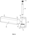
- a first input member 55 and a second input member 58 are provided.
- the input member 55, 58 are configured to accept a hand tool (not shown), such as an Allen key or a hex-wrench for example.
- a hand tool such as an Allen key or a hex-wrench for example.
- the movable jaw 32 may be selectively moved between the open position and the closed position.
- the first input member 56 is rotationally coupled to the side plate 22 to rotate about a first axis 60 ( FIG. 6 ).
- the second input 58 is rotationally coupled to frame 26 about a second axis 62 ( FIG. 4 ).
- the first input member 55 is nestled in a needle bearing 56.
- the second input member 58 is coupled to a bearing, such as a ball bearing 62 ( FIG. 7 ).
- the bearings 56, 62 allow the respective input members 55, 58 to rotate freely when the tool 20 is being actuated by the other input member.
- the movable jaw 32 rotates about a shaft 66.
- the shaft 66 is fixed to the side plates 22, 24.
- the movable jaw 32 includes a linkage portion 68.
- the linkage portion 68 may be arranged on the opposite side of the shaft 66 from the jaw portion 36. It should be appreciated that while the illustrated embodiment shows the linkage portion 68 as being integral with the movable jaw portion 36, this is for exemplary purposes and the claims should not be so limited. In other embodiments, the linkage portion 68 and movable jaw portion 36 are separate components.
- the linkage portion 68 includes a first gear 70 formed to extend from an end of the linkage portion 68.
- the first gear 70 includes a plurality of teeth 72 arranged on a curved surface having a center that is co-axial with the shaft 66.
- the teeth 72 are perpendicular to the side plates 22, 24.
- a jaw insert 74 is coupled to the linkage portion 68 by fasteners 76.
- the jaw insert 74 is formed by casting.
- the jaw insert 74 includes a second gear 76 having a plurality of teeth 78.
- the teeth 78 extend outwardly from a curved end 80 of the jaw insert 74 and are arranged parallel to the side plates 22, 24.
- the center of the curved end 80 is co-axial with the shaft 66.
- the jaw insert 74 includes an arcuate slot 82 having a center co-axial with the shaft 66.
- the slot 82 is sized to allow a shaft 84 to pass therethrough.
- the shaft 84 is fixed to the side plates 22, 24.
- the slot 82 is sized to allow the movable jaw 36 to move between the open position and the closed position without interference from the shaft 84.
- Coupled to rotate on the shaft 84 is a transfer gear 86.
- the transfer gear 86 is arranged to engage the teeth 72 and a first input gear 88 and transfer torque therebetween. It should be appreciated that the gears 86, 88 cooperate with the teeth 72 to rotate the movable jaw 32 between the open position and closed position.
- the first input gear 88 is integrally formed with the first input member 55.
- the second input gear 90 includes a plurality of teeth that a sized and shaped to engage the teeth 78 of second gear 76 and transfer torque from the second input member 58. It should be appreciated that the gears 76, 90 cooperate to rotate the movable jaw 32 between the open position and the closed position.
- the movable jaw 32 is biased into the closed position.
- the biasing of the movable jaw 32 is provided by a compression spring 92 that is arranged between an end 96 of the stationary jaw 30 and a lower surface 98 of the movable jaw 32.
- the end 96 has a blind hole 100 sized to receive an end of the compression spring 92 and the surface 98 also has a blind hole 102 sized to receive an opposite end of the compression spring 92.
- the compression spring applies a force on the movable jaw 32 normal to the bottom surface of the pocket 100. The force applied by the compression spring 92 causes the movable jaw 32 to rotate about the shaft 66 into the closed position (clockwise when viewed from the position of FIG. 7 ).
- a second biasing member such as extension spring 94 for example, is positioned on a side of the shaft 66 opposite the compression spring 92.
- the extension spring 94 is positioned in a pocket defined by blind hole 104 in the movable jaw 32 and blind hole 106 in the stationary jaw 30. The ends of the extension spring 94 are held in place by pins 108, 110 that are pressed into the stationary jaw 30 and the movable jaw 32 respectively.
- the extension spring 94 pulls on the movable jaw 32 to rotate the movable jaw 32 about the shaft 66 towards the closed position (clockwise when viewed from the position of FIG. 7 ).
- the handle 44 is an elongate member that is rotationally attached to the bracket 46 by a pin 48.
- the bracket 46 is fixedly coupled to the side plate 24.
- the handle 44 has a plurality of teeth 52 arranged on one end 50.
- the teeth 52 are radially disposed about the pin 48 when the handle 44 is coupled to the bracket 46.
- the bracket 46 includes a positioning member 112 coupled to an arm 114 of the bracket 46.
- the positioning member 112 has a plurality of teeth 54 arranged on a side opposite the arm 114.
- the teeth 54 cooperate with the teeth 52 to hold the handle 44 in one of a plurality of positions.
- the teeth 52, 54 have a triangular profile. It should be appreciated that the handle 44 will remain in position when the teeth 52 are engaged with the teeth 54.
- a biasing member such as compression spring 116 is arranged between a surface 118 of the handle and an arm 120 of the bracket 46. The spring 116 applies a force to the surface 118 that causes the teeth 52 into engagement with the teeth 54.
- the operator applies a counter force (moving the surface 118 towards the arm 120) until the teeth are disengaged and the handle 44 may be rotated about the pin 48.
- the handle 44 may be selectively moved between a plurality positions, such as but not limited to a closed position ( FIG. 2 ), an open position ( FIG. 11 ) and an extended position ( FIG. 12 ).
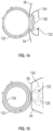
- FIGS. 13-15 the operation is shown of the tool 20 to crimp a band clamp 122.
- the operator initially slides the band clamp 122 onto the tube 124 to be coupled and installs the end of the tube 124 over a fitting 126.
- the band clamp 122 has a u-shaped section, sometimes referred to as an "ear" 128.
- the ear 128 is inserted into the gap 42 between the movable jaw 32 and the stationary jaw 30 with the movable jaw 32 in the open position.
- the crimping mechanism By actuating the first input member 55 or the second input member 58, the crimping mechanism engages the sides of the ear 128 causing the ear '18 to deform by bending inwardly ( FIG. 14 ). As the ear 128 deforms, the band portion of the band clamp 122 is pulled towards the ear 128. This has the effect of reducing the diameter of the band clamp 122, tightening the band clamp 122 on the tube 124 and the fitting 126. As the operator continues to actuate either the first input member 55 or the second input member 58, the crimping mechanism moves the movable jaw 32 towards the stationary jaw 30 until the desired amount of crimp is achieved ( FIG. 15 ). In an embodiment, the jaw portions 34, 36 each have a curved surface 130 that defines an area 132 that allows the ear 128 to deform as the jaw portions 34, 36 are closed.
- the tool 20 may be used with other types of clamps. In still other embodiments, the tool 20 may be adapted to perform a cutting operation or be used in cooperation with ring clamps.
- Technical effects and benefits of some embodiments include providing a tool that allows the crimping of a clamp from multiple input positions. Further technical benefits include a crimping mechanism that provides a compact crimping tool having a handle that may be moved to multiple positions to facilitate holding of the tool.
Landscapes
- Engineering & Computer Science (AREA)
- Mechanical Engineering (AREA)
- Manufacturing & Machinery (AREA)
- Clamps And Clips (AREA)
- Hand Tools For Fitting Together And Separating, Or Other Hand Tools (AREA)
- Manufacturing Of Electrical Connectors (AREA)
Claims (11)
- Crimpwerkzeug (20), umfassend:einen feststehenden Backen (30);einen beweglichen Backen (32) neben dem feststehenden Backen (30), wobei der bewegliche Backen (32) von einer offenen Position in eine geschlossene Position beweglich ist;ein Gestänge, das an einem Ende mit dem beweglichen Backen betriebsmäßig gekoppelt ist, wobei das Gestänge um eine Achse drehbar ist;ein erstes Eingabeelement (55), das betriebsmäßig mit dem Gestänge gekoppelt ist, um das Gestänge um die Achse zu drehen, wobei das erste Eingabeelement (55) um eine erste Achse (60) rotiert; undein zweites Eingabeelement (58), das betriebsmäßig mit dem Gestänge gekoppelt ist, um das Gestänge um die Achse zu drehen, wobei das zweite Eingabeelement (58) um eine zweite Achse (62) rotiert, wobei die zweite Achse (62) im Wesentlichen senkrecht zur ersten Achse (60) ist;dadurch gekennzeichnet, dassdas erste und das zweite Eingabeelement (55, 58) konfiguriert sind, um ein Handwerkzeug aufzunehmen.
- Crimpwerkzeug (20) nach Anspruch 1, wobei das Gestänge mit dem beweglichen Backen (32) einteilig ausgebildet ist.
- Crimpwerkzeug nach Anspruch 2, wobei das Gestänge zuerst eine erste Vielzahl von Zahnrädern (72) umfasst, die angeordnet sind, um mit dem ersten Eingabeelement (55) einzugreifen, und eine zweite Vielzahl von Zahnrädern (78), die angeordnet sind, um mit dem zweiten Eingabeelement (58) einzugreifen.
- Crimpwerkzeug (20) nach Anspruch 3, ferner umfassend ein Übertragungszahnrad (86), das zwischen dem ersten Eingabeelement (55) und der ersten Vielzahl von Zahnrädern (72) gekoppelt ist.
- Crimpwerkzeug nach Anspruch 1, ferner umfassend:einen ersten Rahmen (25) und einen zweiten Rahmen, die auf gegenüberliegenden Seiten des Gestänges angeordnet sind,wobei die Achse (66) mit dem ersten Rahmen und dem zweiten Rahmen gekoppelt ist; undeinen Griff (44), der beweglich mit dem ersten Rahmen gekoppelt ist.
- Crimpwerkzeug nach Anspruch 5, wobei der Griff (44) zwischen einer Vielzahl von Positionen beweglich ist.
- Crimpwerkzeug nach Anspruch 6, wobei der Griff umfasst:eine Klammer (46), die mit der ersten Seite gekoppelt ist;einen Griffteil, der drehbar mit der Klammer (46) gekoppelt ist, wobei der Griff (44) eine Vielzahl von ersten Zähnen (52) an einem Ende aufweist;ein Positionselement mit einer Vielzahl von zweiten Zähnen (54), die angeordnet sind, um mit der Vielzahl von ersten Zähnen (52) einzugreifen; undein Vorspannelement, das zwischen der Klammer (46) und dem Griffteil angeordnet ist, um die Vielzahl von ersten Zähnen (52) in Eingriff mit der Vielzahl von zweiten Zähnen (54) vorzuspannen.
- Crimpwerkzeug (20) nach Anspruch 1, ferner umfassend eine Zugfeder (94), die mit dem beweglichen Backen (32) und dem feststehenden Backen (30) gekoppelt ist, wobei die Zugfeder (94) zwischen der Achse und einem ersten Backenteil (34) des beweglichen Backens (32) und einem zweiten Backenteil (36) des feststehenden Backens (30) positioniert ist.
- Crimpwerkzeug (20) nach Anspruch 4, wobei der erste Backenteil (34) und der zweite Backenteil (36) jeweils eine Ausnehmung (38, 40) aufweisen, wobei die Ausnehmungen (38, 40) zusammenwirken, um eine Öffnung in der gecrimpten Position zu bilden, die bemessen ist, um ein vorbestimmtes Maß an Crimp in einer Bandklemme zu erzeugen.
- Crimpwerkzeug (20) nach Anspruch 5, wobei die Öffnung von einer Mittellinie des beweglichen Backens (32) und des feststehenden Backens (30) versetzt ist.
- Crimpwerkzeug (20) nach Anspruch 1, ferner umfassend eine Druckfeder (92), die zwischen dem feststehenden Backen (30) und dem Gestänge gekoppelt ist und angeordnet ist, um den beweglichen Backen (32) in die gecrimpte Position vorzuspannen.
Applications Claiming Priority (2)
| Application Number | Priority Date | Filing Date | Title |
|---|---|---|---|
| US201862643254P | 2018-03-15 | 2018-03-15 | |
| PCT/US2019/022022 WO2019178209A1 (en) | 2018-03-15 | 2019-03-13 | Crimping tool |
Publications (4)
| Publication Number | Publication Date |
|---|---|
| EP3766147A1 EP3766147A1 (de) | 2021-01-20 |
| EP3766147A4 EP3766147A4 (de) | 2022-03-16 |
| EP3766147B1 true EP3766147B1 (de) | 2025-06-25 |
| EP3766147C0 EP3766147C0 (de) | 2025-06-25 |
Family
ID=67908077
Family Applications (1)
| Application Number | Title | Priority Date | Filing Date |
|---|---|---|---|
| EP19768390.7A Active EP3766147B1 (de) | 2018-03-15 | 2019-03-13 | Crimpwerkzeug |
Country Status (7)
| Country | Link |
|---|---|
| US (1) | US11364532B2 (de) |
| EP (1) | EP3766147B1 (de) |
| JP (1) | JP7197596B2 (de) |
| CN (1) | CN111788745B (de) |
| ES (1) | ES3037271T3 (de) |
| PL (1) | PL3766147T3 (de) |
| WO (1) | WO2019178209A1 (de) |
Families Citing this family (1)
| Publication number | Priority date | Publication date | Assignee | Title |
|---|---|---|---|---|
| US12611754B2 (en) | 2022-07-29 | 2026-04-28 | Black & Decker Inc. | Crimping and/or pinching accessory for power tool |
Family Cites Families (41)
| Publication number | Priority date | Publication date | Assignee | Title |
|---|---|---|---|---|
| GB115120A (de) | ||||
| GB415120A (en) * | 1933-02-16 | 1934-08-16 | Arthur John Muter | Pliers, clippers or pinchers |
| US2808748A (en) * | 1953-10-29 | 1957-10-08 | Woodrow W Bledsoe | Gear-operated toggle-controlled crimping tool |
| JPS5045190Y2 (de) * | 1971-07-02 | 1975-12-22 | ||
| JPS5552632Y2 (de) * | 1976-04-21 | 1980-12-06 | ||
| GB2083392A (en) * | 1980-09-08 | 1982-03-24 | Graham Douglas Ian | Wrench with rapid rotation facility |
| DE3226546C2 (de) * | 1982-07-13 | 1984-05-03 | Mannesmann AG, 4000 Düsseldorf | Klemmzangenkopf |
| US4660241A (en) * | 1985-10-10 | 1987-04-28 | Chen Ching Win | Multipurpose pliers |
| US4747588A (en) | 1986-08-15 | 1988-05-31 | Dillhoff George A | Universal clamping tool |
| US4757588A (en) | 1987-05-15 | 1988-07-19 | Ljudo Churchich | Push-on hose pliers |
| DE3719442A1 (de) * | 1987-06-11 | 1988-12-22 | Pfisterer Elektrotech Karl | Tragbare presse zur herstellung von pressverbindungen |
| SE9002366L (sv) * | 1989-08-11 | 1991-02-12 | Petersen Mfg | Snabbinstaellning foer kaeftarna vid verktyg och liknande |
| DE4139260A1 (de) * | 1991-11-29 | 1993-06-03 | Bessey & Sohn | Spanneinrichtung |
| US5259276A (en) * | 1992-08-31 | 1993-11-09 | Baron George A | Ratchet wrench including toothless drive |
| US5280716A (en) * | 1992-11-13 | 1994-01-25 | The Whitaker Corporation | Crimping tool |
| DE19644807A1 (de) * | 1996-10-28 | 1998-05-07 | Connectool Gmbh & Co | Werkzeug mit einem Mehrfach-Kniehebelmechanismus |
| CN2282282Y (zh) * | 1996-11-15 | 1998-05-20 | 陈庆珍 | 改良的端子压接钳 |
| US6164107A (en) * | 1996-12-12 | 2000-12-26 | Korba, Jr.; William | Radius crimping tool |
| US5870925A (en) * | 1997-06-27 | 1999-02-16 | The Whitaker Corporation | Hand tool crimping a terminal onto a conductor |
| DE29806179U1 (de) | 1998-04-03 | 1998-10-08 | Connectool GmbH & Co., 32758 Detmold | Crimpzange |
| US6220126B1 (en) * | 1998-07-31 | 2001-04-24 | Alberto G. Domenge | Hand tool having pivoted handles |
| JP2000068024A (ja) * | 1998-08-24 | 2000-03-03 | Takeuchi Seisakusho:Kk | 手動式圧着工具 |
| US6138346A (en) * | 1998-12-21 | 2000-10-31 | Connectool Inc. | Portable hand-held battery-powered crimping tool |
| US20030230132A1 (en) * | 2002-06-17 | 2003-12-18 | Emerson Electric Co. | Crimping apparatus |
| US7503201B2 (en) * | 2005-03-25 | 2009-03-17 | Mil3, Inc. | Two-stroke tool |
| US20070209484A1 (en) | 2006-03-13 | 2007-09-13 | Chervenak Thomas M | Locking pliers |
| CN200991860Y (zh) | 2006-09-27 | 2007-12-19 | 天津市润实科技发展有限公司 | 一种手动式步进钳 |
| US7454999B2 (en) * | 2007-02-18 | 2008-11-25 | Ming-Chieh Wu | Locking pliers |
| US7957831B2 (en) | 2008-04-04 | 2011-06-07 | Isaacs Robert E | System and device for designing and forming a surgical implant |
| DE202010005761U1 (de) * | 2010-04-17 | 2011-09-23 | Weidmüller Interface GmbH & Co. KG | Handhabungsvorrichtung für ein zangenartiges Werkzeug |
| DE102011056851A1 (de) * | 2010-12-22 | 2012-06-28 | Rennsteig Werkzeuge Gmbh | Zange |
| US9839463B2 (en) | 2012-09-06 | 2017-12-12 | Stryker European Holdings I, Llc | Instrument for use in bending surgical devices |
| US9216494B2 (en) * | 2013-03-11 | 2015-12-22 | Chiu-Chi LAI | Pincer structure |
| US10144117B2 (en) * | 2013-05-09 | 2018-12-04 | Oleg Aleksandrovich Khristyuchenko | Load induced mechanism system |
| US20150072572A1 (en) * | 2013-09-11 | 2015-03-12 | James Frank Easterling | Locking Electrical Connector |
| US9421596B2 (en) | 2014-04-16 | 2016-08-23 | University of Alaska Anchorage | Bending instrument and methods of using same |
| CN204367412U (zh) * | 2014-12-27 | 2015-06-03 | 山西大运汽车制造有限公司 | 一种重卡制动管束铆钳 |
| EP3208044A1 (de) * | 2016-02-18 | 2017-08-23 | Wezag GmbH Werkzeugfabrik | Zange mit einem kniehebeltrieb |
| DE102018121971A1 (de) * | 2018-09-10 | 2020-03-12 | Gustav Klauke Gmbh | Presswerkzeug |
| EP3904006B1 (de) * | 2020-04-28 | 2023-06-07 | WEZAG GmbH & Co. KG | Crimpzangen-gesenk und crimpzange |
| US12040581B2 (en) * | 2020-06-26 | 2024-07-16 | Ilsco, Llc | Crimping assembly, tool and die design |
-
2019
- 2019-03-13 US US16/979,720 patent/US11364532B2/en active Active
- 2019-03-13 ES ES19768390T patent/ES3037271T3/es active Active
- 2019-03-13 PL PL19768390.7T patent/PL3766147T3/pl unknown
- 2019-03-13 WO PCT/US2019/022022 patent/WO2019178209A1/en not_active Ceased
- 2019-03-13 CN CN201980015584.0A patent/CN111788745B/zh active Active
- 2019-03-13 EP EP19768390.7A patent/EP3766147B1/de active Active
- 2019-03-13 JP JP2020546140A patent/JP7197596B2/ja active Active
Also Published As
| Publication number | Publication date |
|---|---|
| EP3766147A4 (de) | 2022-03-16 |
| JP7197596B2 (ja) | 2022-12-27 |
| WO2019178209A1 (en) | 2019-09-19 |
| EP3766147A1 (de) | 2021-01-20 |
| PL3766147T3 (pl) | 2025-10-20 |
| JP2021516166A (ja) | 2021-07-01 |
| US20210039155A1 (en) | 2021-02-11 |
| EP3766147C0 (de) | 2025-06-25 |
| CN111788745A (zh) | 2020-10-16 |
| US11364532B2 (en) | 2022-06-21 |
| ES3037271T3 (en) | 2025-09-30 |
| CN111788745B (zh) | 2022-07-26 |
Similar Documents
| Publication | Publication Date | Title |
|---|---|---|
| EP1732735B1 (de) | Verstellbares greifwerkzeug | |
| AU2006235501B2 (en) | Adjustable gripping tool | |
| EP2623265A2 (de) | Einstellbares Greifwerkzeug | |
| EP0997233A2 (de) | Spannwerkzeug, insbesondere Spannzwinge, Spannstock oder Spanntisch | |
| EP2352609B1 (de) | Manuell betätigtes Werkzeug zum Aufweiten von Rohren | |
| EP3251797B1 (de) | Zange | |
| JP6884951B6 (ja) | ハンドプライヤ群 | |
| JP7593630B2 (ja) | 圧着工具ダイおよび圧着工具 | |
| US10953527B2 (en) | Crimping tool for band clamp | |
| JP2022519611A (ja) | 接続端末および接続端末ブロック | |
| EP3766147B1 (de) | Crimpwerkzeug | |
| US8087280B2 (en) | Spreading pliers | |
| EP1722928B1 (de) | Einhandspannzwinge | |
| EP2640533B1 (de) | Haltevorrichtung für ein bördelgerät sowie bördelgerät zum bördeln von rohrenden | |
| EP2385891B1 (de) | Zange zur herstellung einer schiebehülsenverbindung | |
| US11623328B2 (en) | Multi-pump hand tool | |
| WO2007102034A1 (en) | Apparatus for manual bending of tubes | |
| EP4360806A1 (de) | Verbundbetätigungswerkzeug | |
| EP1097028A1 (de) | Werkzeug mit selbstverriegelndem griff, auswechselbaren kopfstücken und spannvorrichtung zum befestigen an einem arbeitstisch |
Legal Events
| Date | Code | Title | Description |
|---|---|---|---|
| STAA | Information on the status of an ep patent application or granted ep patent |
Free format text: STATUS: THE INTERNATIONAL PUBLICATION HAS BEEN MADE |
|
| PUAI | Public reference made under article 153(3) epc to a published international application that has entered the european phase |
Free format text: ORIGINAL CODE: 0009012 |
|
| STAA | Information on the status of an ep patent application or granted ep patent |
Free format text: STATUS: REQUEST FOR EXAMINATION WAS MADE |
|
| 17P | Request for examination filed |
Effective date: 20200904 |
|
| AK | Designated contracting states |
Kind code of ref document: A1 Designated state(s): AL AT BE BG CH CY CZ DE DK EE ES FI FR GB GR HR HU IE IS IT LI LT LU LV MC MK MT NL NO PL PT RO RS SE SI SK SM TR |
|
| AX | Request for extension of the european patent |
Extension state: BA ME |
|
| DAV | Request for validation of the european patent (deleted) | ||
| DAX | Request for extension of the european patent (deleted) | ||
| RIC1 | Information provided on ipc code assigned before grant |
Ipc: B25G 1/06 20060101ALI20211104BHEP Ipc: B25B 27/10 20060101ALI20211104BHEP Ipc: H01R 43/04 20060101ALI20211104BHEP Ipc: B25B 27/14 20060101ALI20211104BHEP Ipc: B25B 25/00 20060101ALI20211104BHEP Ipc: B25B 7/22 20060101ALI20211104BHEP Ipc: B25B 7/12 20060101ALI20211104BHEP Ipc: H01R 43/042 20060101AFI20211104BHEP |
|
| A4 | Supplementary search report drawn up and despatched |
Effective date: 20220211 |
|
| RIC1 | Information provided on ipc code assigned before grant |
Ipc: B25G 1/06 20060101ALI20220207BHEP Ipc: B25B 27/10 20060101ALI20220207BHEP Ipc: H01R 43/04 20060101ALI20220207BHEP Ipc: B25B 27/14 20060101ALI20220207BHEP Ipc: B25B 25/00 20060101ALI20220207BHEP Ipc: B25B 7/22 20060101ALI20220207BHEP Ipc: B25B 7/12 20060101ALI20220207BHEP Ipc: H01R 43/042 20060101AFI20220207BHEP |
|
| STAA | Information on the status of an ep patent application or granted ep patent |
Free format text: STATUS: EXAMINATION IS IN PROGRESS |
|
| 17Q | First examination report despatched |
Effective date: 20231214 |
|
| GRAP | Despatch of communication of intention to grant a patent |
Free format text: ORIGINAL CODE: EPIDOSNIGR1 |
|
| STAA | Information on the status of an ep patent application or granted ep patent |
Free format text: STATUS: GRANT OF PATENT IS INTENDED |
|
| INTG | Intention to grant announced |
Effective date: 20250219 |
|
| GRAS | Grant fee paid |
Free format text: ORIGINAL CODE: EPIDOSNIGR3 |
|
| GRAA | (expected) grant |
Free format text: ORIGINAL CODE: 0009210 |
|
| STAA | Information on the status of an ep patent application or granted ep patent |
Free format text: STATUS: THE PATENT HAS BEEN GRANTED |
|
| AK | Designated contracting states |
Kind code of ref document: B1 Designated state(s): AL AT BE BG CH CY CZ DE DK EE ES FI FR GB GR HR HU IE IS IT LI LT LU LV MC MK MT NL NO PL PT RO RS SE SI SK SM TR |
|
| REG | Reference to a national code |
Ref country code: GB Ref legal event code: FG4D |
|
| REG | Reference to a national code |
Ref country code: CH Ref legal event code: EP |
|
| REG | Reference to a national code |
Ref country code: CH Ref legal event code: EP |
|
| REG | Reference to a national code |
Ref country code: IE Ref legal event code: FG4D |
|
| REG | Reference to a national code |
Ref country code: DE Ref legal event code: R096 Ref document number: 602019071590 Country of ref document: DE |
|
| U01 | Request for unitary effect filed |
Effective date: 20250724 |
|
| U07 | Unitary effect registered |
Designated state(s): AT BE BG DE DK EE FI FR IT LT LU LV MT NL PT RO SE SI Effective date: 20250731 |
|
| REG | Reference to a national code |
Ref country code: ES Ref legal event code: FG2A Ref document number: 3037271 Country of ref document: ES Kind code of ref document: T3 Effective date: 20250930 |
|
| PG25 | Lapsed in a contracting state [announced via postgrant information from national office to epo] |
Ref country code: GR Free format text: LAPSE BECAUSE OF FAILURE TO SUBMIT A TRANSLATION OF THE DESCRIPTION OR TO PAY THE FEE WITHIN THE PRESCRIBED TIME-LIMIT Effective date: 20250926 Ref country code: NO Free format text: LAPSE BECAUSE OF FAILURE TO SUBMIT A TRANSLATION OF THE DESCRIPTION OR TO PAY THE FEE WITHIN THE PRESCRIBED TIME-LIMIT Effective date: 20250925 |
|
| PG25 | Lapsed in a contracting state [announced via postgrant information from national office to epo] |
Ref country code: HR Free format text: LAPSE BECAUSE OF FAILURE TO SUBMIT A TRANSLATION OF THE DESCRIPTION OR TO PAY THE FEE WITHIN THE PRESCRIBED TIME-LIMIT Effective date: 20250625 |
|
| PG25 | Lapsed in a contracting state [announced via postgrant information from national office to epo] |
Ref country code: RS Free format text: LAPSE BECAUSE OF FAILURE TO SUBMIT A TRANSLATION OF THE DESCRIPTION OR TO PAY THE FEE WITHIN THE PRESCRIBED TIME-LIMIT Effective date: 20250925 |
|
| PG25 | Lapsed in a contracting state [announced via postgrant information from national office to epo] |
Ref country code: IS Free format text: LAPSE BECAUSE OF FAILURE TO SUBMIT A TRANSLATION OF THE DESCRIPTION OR TO PAY THE FEE WITHIN THE PRESCRIBED TIME-LIMIT Effective date: 20251025 |
|
| PG25 | Lapsed in a contracting state [announced via postgrant information from national office to epo] |
Ref country code: SM Free format text: LAPSE BECAUSE OF FAILURE TO SUBMIT A TRANSLATION OF THE DESCRIPTION OR TO PAY THE FEE WITHIN THE PRESCRIBED TIME-LIMIT Effective date: 20250625 |
|
| PG25 | Lapsed in a contracting state [announced via postgrant information from national office to epo] |
Ref country code: CZ Free format text: LAPSE BECAUSE OF FAILURE TO SUBMIT A TRANSLATION OF THE DESCRIPTION OR TO PAY THE FEE WITHIN THE PRESCRIBED TIME-LIMIT Effective date: 20250625 |
|
| PG25 | Lapsed in a contracting state [announced via postgrant information from national office to epo] |
Ref country code: SK Free format text: LAPSE BECAUSE OF FAILURE TO SUBMIT A TRANSLATION OF THE DESCRIPTION OR TO PAY THE FEE WITHIN THE PRESCRIBED TIME-LIMIT Effective date: 20250625 |
|
| REG | Reference to a national code |
Ref country code: CH Ref legal event code: U11 Free format text: ST27 STATUS EVENT CODE: U-0-0-U10-U11 (AS PROVIDED BY THE NATIONAL OFFICE) Effective date: 20260401 |
|
| PGFP | Annual fee paid to national office [announced via postgrant information from national office to epo] |
Ref country code: GB Payment date: 20260304 Year of fee payment: 8 |
|
| PGFP | Annual fee paid to national office [announced via postgrant information from national office to epo] |
Ref country code: TR Payment date: 20260225 Year of fee payment: 8 |
|
| PGFP | Annual fee paid to national office [announced via postgrant information from national office to epo] |
Ref country code: PL Payment date: 20260226 Year of fee payment: 8 |
|
| PLBE | No opposition filed within time limit |
Free format text: ORIGINAL CODE: 0009261 |
|
| STAA | Information on the status of an ep patent application or granted ep patent |
Free format text: STATUS: NO OPPOSITION FILED WITHIN TIME LIMIT |