EP3251797B1 - Zange - Google Patents
Zange Download PDFInfo
- Publication number
- EP3251797B1 EP3251797B1 EP15879362.0A EP15879362A EP3251797B1 EP 3251797 B1 EP3251797 B1 EP 3251797B1 EP 15879362 A EP15879362 A EP 15879362A EP 3251797 B1 EP3251797 B1 EP 3251797B1
- Authority
- EP
- European Patent Office
- Prior art keywords
- clamp
- handle
- limiting
- tooth
- limiting block
- Prior art date
- Legal status (The legal status is an assumption and is not a legal conclusion. Google has not performed a legal analysis and makes no representation as to the accuracy of the status listed.)
- Active
Links
- XLYOFNOQVPJJNP-UHFFFAOYSA-N water Substances O XLYOFNOQVPJJNP-UHFFFAOYSA-N 0.000 claims description 26
- 230000000694 effects Effects 0.000 description 8
- 238000010586 diagram Methods 0.000 description 4
- 230000005540 biological transmission Effects 0.000 description 2
- 230000003247 decreasing effect Effects 0.000 description 1
- 238000003780 insertion Methods 0.000 description 1
- 230000037431 insertion Effects 0.000 description 1
- 230000000717 retained effect Effects 0.000 description 1
- 238000000926 separation method Methods 0.000 description 1
- 238000004904 shortening Methods 0.000 description 1
Images


Classifications
-
- B—PERFORMING OPERATIONS; TRANSPORTING
- B25—HAND TOOLS; PORTABLE POWER-DRIVEN TOOLS; MANIPULATORS
- B25B—TOOLS OR BENCH DEVICES NOT OTHERWISE PROVIDED FOR, FOR FASTENING, CONNECTING, DISENGAGING OR HOLDING
- B25B7/00—Pliers; Other hand-held gripping tools with jaws on pivoted limbs; Details applicable generally to pivoted-limb hand tools
- B25B7/06—Joints
- B25B7/10—Joints with adjustable fulcrum
-
- B—PERFORMING OPERATIONS; TRANSPORTING
- B25—HAND TOOLS; PORTABLE POWER-DRIVEN TOOLS; MANIPULATORS
- B25B—TOOLS OR BENCH DEVICES NOT OTHERWISE PROVIDED FOR, FOR FASTENING, CONNECTING, DISENGAGING OR HOLDING
- B25B7/00—Pliers; Other hand-held gripping tools with jaws on pivoted limbs; Details applicable generally to pivoted-limb hand tools
- B25B7/06—Joints
- B25B7/08—Joints with fixed fulcrum
-
- B—PERFORMING OPERATIONS; TRANSPORTING
- B25—HAND TOOLS; PORTABLE POWER-DRIVEN TOOLS; MANIPULATORS
- B25B—TOOLS OR BENCH DEVICES NOT OTHERWISE PROVIDED FOR, FOR FASTENING, CONNECTING, DISENGAGING OR HOLDING
- B25B7/00—Pliers; Other hand-held gripping tools with jaws on pivoted limbs; Details applicable generally to pivoted-limb hand tools
- B25B7/12—Pliers; Other hand-held gripping tools with jaws on pivoted limbs; Details applicable generally to pivoted-limb hand tools involving special transmission means between the handles and the jaws, e.g. toggle levers, gears
-
- B—PERFORMING OPERATIONS; TRANSPORTING
- B25—HAND TOOLS; PORTABLE POWER-DRIVEN TOOLS; MANIPULATORS
- B25B—TOOLS OR BENCH DEVICES NOT OTHERWISE PROVIDED FOR, FOR FASTENING, CONNECTING, DISENGAGING OR HOLDING
- B25B7/00—Pliers; Other hand-held gripping tools with jaws on pivoted limbs; Details applicable generally to pivoted-limb hand tools
- B25B7/14—Locking means
Definitions
- the present invention relates to a hand tool, and more particularly, to a clamp.
- a clamp is a relatively small and light hand tool product and is widely used for household non-professional emergency or simple article clamping or mounting.
- a clamp has a pair of clamp bodies and each of the clamp bodies comprises a clamp jaw and a handle.
- the pair of clamp bodies is pivotally connected to each other with a connection point being between the clamp jaw and the handle.
- a part as a pivot is generally movable on one of clamp bodies to adjust the opening width between the clamp jaws.
- US 1 145 067 A discloses a wrench comprising a recessed movable jaw provided with an opening in which a lever arm is pivoted.
- the lever arm is rigidly secured by a single pin adapted to travel in a slot provided with notches.
- DE 298 16 558 U1 discloses a plier comprising a movable jaw being a clamping portion and a lower end of the clamping portion having a single insertion tooth rotatably received in a receiving slot.
- DE 130 913C discloses a pair of pliers.
- the one leg of the pliers is provided with an eye in which a single pin is arranged, which serves as a mounting and pivot point of the pressure leg.
- the leg is provided with a slot, in which the pin moves.
- the present invention provides a clamp having a labor-saving structure, which achieves the effect of further labor-saving by the structural arrangement thereof without increasing the length of the handle sections, compared to the clamp having the conventional structure. Also, the present invention provides a water pump clamp having this labor-saving structure and provided with a structure facilitating adjustment of an opening width between clamp jaws.
- the present invention provides a clamp as defined in claim 1. Further, a limiting structure is disposed on one of the first clamp jaw and the first handle, and a limiting member to be engaged with the limiting structure is disposed on the other of the first clamp jaw and the first handle. The limiting member is partially or completely disposed within the limiting structure and is movable within the limiting structure, to form movable connection between the first clamp jaw and the first handle.
- the limiting structure is an elongated hole or slot, and the limiting member is movable along the length direction of the elongated hole or slot.
- the limiting region is an elongated hole or slot.
- first clamp jaw is pivotally connected to the limiting block.
- the first handle is pivotally connected to the limiting block.
- the second clamp body comprises a second clamp jaw and a second handle, and the limiting region is disposed between the second clamp jaw and the second handle.
- first connecting position is closer to the second clamp jaw than the second connecting position.
- the limiting region comprises a locking structure, and a locking portion to be engaged with the locking structure is disposed on the limiting block.
- the locking structure is engaged with the locking portion, the position of the limiting block within the limiting region is kept fixed, at which point the limiting block is in a locked position, and when the locking structure is disengaged from the locking portion, the limiting block is movable within the limiting region, at which point the limiting block is in a released position.
- the locking structure is a tooth-shaped profile
- the locking portion is a tooth to be engaged with the tooth-shaped profile.
- an elastic member is disposed on the limiting block, and the elastic member holds the limiting block in the locking position.
- the elastic member is a spring.
- the elastic member is disposed at a position engagable with the first handle, so as to resist a force from the elastic member by driving the first handle, thereby driving the limiting block to the released position.
- the distance of the elastic member to the first connecting position is greater than the distance of the elastic member to the second connecting position.
- the tooth-shaped profile and/or the limiting block is disposed such that when the limiting block is moved toward the second clamp jaw, a force from the tooth-shaped profile on the tooth moves the limiting block to the released position; and when the limiting block is moved toward the second handle, a force from the tooth-shaped profile on the tooth holds the limiting block in the locking position.
- clamp is a water pump clamp.
- the labor-saving clamp according to the present invention creatively adapts two lever systems, such that equivalent force arms in actual use are increased without changing the handle length (or the tool size), achieving the purpose of labor-saving. It has a simple structure and is easy to implement, and desired equivalent force arms can be obtained by adjusting the shape or length of the components in design, and the opening width between the clamp jaws can also be quickly adjusted, which is simple in operation and reliable in use.
- a clamp according to the present invention comprises a first clamp body 1 and a second clamp body 2.
- the first clamp body 1 comprises a first clamp jaw 3 and a first handle 4
- the second clamp body 2 comprises a second clamp jaw 5 and a second handle 6.
- the second clamp body 2 is pivotally connected to the first clamp jaw 3 by a rivet 9 (a first connecting position)
- the second clamp body 2 is pivotally connected to the first handle 4 by a rivet 10 (a second connecting position).
- An elongated hole 11 is disposed on the first clamp jaw 3, and the first clamp jaw 3 and the first handle 4 are connected by a rivet 12 passing through the elongated hole 11, to form movable connection between the first clamp jaw 3 and the first handle 4.
- the elongated hole 11 may be replaced by a slot providing the same effect; the elongated hole 11 may be disposed on the first handle 4, and the position of the rivet 12 relative to the first clamp jaw 3 is kept fixed, and so on.
- the clamp has the labor-saving effect because two lever systems are involved, i.e. one lever system with the first clamp jaw 3 as a lever and the rivet 9 as a shaft, and the other lever system with the first handle 4 as a lever and the rivet 10 as a shaft.
- the force transmission of the two lever systems is achieved by the elongated hole 11 and the rivet 12.
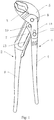
- FIG. 1 to FIG. 5 show a water pump clamp having the abovementioned labor-saving structure according to the present invention, comprising a first clamp body 1 and a second clamp body 2.
- the first clamp body 1 comprises a first clamp jaw 3 and a first handle 4
- the second clamp body 2 comprises a second clamp jaw 5, a second handle 6, and an elongated hole 7.
- the elongated hole 7 is disposed between the second clamp jaw 5 and the second handle 6, and a tooth block 8 is disposed within the elongated hole 7.
- the second clamp body 2 passes through between bifurcations on the first clamp jaw 3 and the first handle 4, and then the first clamp jaw 3 is pivotally connected to the tooth block 8 by a rivet 9, and the first handle 4 is pivotally connected to the tooth block 8 by a rivet 10.
- the tooth block 8 is limited in the elongated hole 7, is not movable in an axial direction of the pivots (the rivet 9 and the rivet 10) and is only movable within the elongated hole 7 in a radial direction.
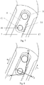
- FIG. 5 is a partially enlarged view of the interconnects of the first clamp jaw 3, the first handle 4 and the tooth block 8 in FIG. 1 , in which the tooth block 8 being shielded is shown in a dashed line.
- the rivet 9 is closer in position to the second clamp jaw 5 than the rivet 10.
- An elongated hole 11 is disposed on the first clamp jaw 3, and the first clamp jaw 3 and the first handle 4 are connected by a rivet 12 passing through the elongated hole 11, to form movable connection between the first clamp jaw 3 and the first handle 4.
- the position of the rivet 12 relative to the first handle 4 is kept fixed, and the rivet 12 is movable within the elongated hole 11 relative to the first clamp jaw 3.
- the rivet 12 is movable along the length direction of the elongated hole 11.
- the position of the rivet 12 in the elongated hole 11 varies with the relative position of the first clamp jaw 3 and the first handle 4.
- the elongated hole 11 and the elongated hole 7 may be replaced by slots providing the same effect; the elongated hole 11 may be disposed on the first handle 4, and the position of the rivet 12 relative to the first clamp jaw 3 is kept fixed, and so on.
- FIG. 6 is a force analysis diagram of the water pump clamp shown in FIG. 1 , in which two lever systems are involved, i.e. one lever system with the first clamp jaw 3 as a lever and the rivet 9 as a shaft, and the other lever system with the first handle 4 as a lever and the rivet 10 as a shaft.
- the force transmission of the two lever systems is achieved by the elongated hole 11 and the rivet 12.
- F1 is a force applied to the first handle 4
- F2 and F2' are a force and a reaction force between the first clamp jaw 3 (particularly the elongated hole 11) and the first handle 4 (particularly the rivet 12)
- F3 is a reaction force acted onto the first clamp jaw 3 from the second clamp jaw 5 (the force comes from an object being champed when the object is champed between the clamp jaws).
- the water pump clamp is disposed with only one lever system, namely, the first clamp jaw is fixedly connected to the first handle and connected to the tooth block by only one pivot, according to the change in position of the pivot on the tooth block, the maximum of the force arm of the handle at one end is b+d (with the rivet 9 as the pivot).
- the water pump clamp using the double-lever system can provide a greater clamping force; and when the clamp jaws are at the same clamping force, the force required to be applied to the handles is smaller for the water pump clamp using the double-lever system.
- a tooth-shaped profile 13 is disposed at one side within the elongated hole 7, and a tooth 14 to be engaged with the tooth-shaped profile 13 is provided on the tooth block 8.
- a spring 15 is disposed at the other side on the tooth block 8 opposite to the tooth 14, and the spring 15 is located at one end close to the rivet 10. Under the action of the spring force of the spring 15, the tooth 14 on the tooth block 8 is engaged with the tooth-shaped profile 13, to achieve the locking of the tooth block 8 within the elongated hole 7.
- the tooth block 8 can be driven by the first handle 4 to compress the spring 15 such that the tooth-shaped profile 13 is disengaged from the tooth 14. At this time, the tooth block 8 can be driven by the first handle 4 to slide within the elongated hole 7.
- the locking manner between the tooth-shaped profile 13 and the tooth block 8 is further structurally disposed such that when the spring 15 is not compressed by the first handle 4 and the tooth block 8 can be only driven to move toward the second clamp jaw 5, a force by the tooth-shaped profile 13 on the tooth 14 can compress the spring 15 to disengage the tooth-shaped profile 13 from the tooth 14; when the spring 15 is not compressed by the first handle 4 and the tooth block 8 can be only driven to move toward the second handle 6, the force by the tooth-shaped profile 13 on the tooth 14 allows the tooth-shaped profile 13 and the tooth 14 to be retained in engagement.
- FIG. 8 is a force analysis diagram of the tooth block 8 shown in FIG. 7 when translating in the elongated hole 7.
- a force F4 by the spring 15 on the tooth block 8 rotates the tooth block 8 counterclockwise
- a force F5 acted onto the tooth 14 on the tooth block 8 from the tooth-shaped profile 13 rotates the tooth block 8 clockwise, namely, the rotation directions of the tooth block 8 by F4 and F5 are opposite to each other.
- the tooth block 8 will be rotated clockwise, such that the tooth block 8 can be driven to translate toward the second clamp jaw 5, namely, the adjustment in position of the tooth block 8 can be achieved, during which no force is required to be directly applied to the spring 15 to compress it.
- F4 and F6 cause the tooth block 8 to have the tendency of counterclockwise rotation, to maintain the engagement of the tooth-shaped profile 13 and the tooth 14.
- an external force must be applied to compress the spring such that the tooth block 8 is rotated clockwise to disengage the tooth-shaped profile 13 from the tooth 14, and then quickly translated toward the second handle 6.
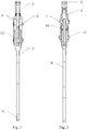
- Such a structural design enables the water pump clamp to achieve fast adjustment in a single direction, facilitating rapid clamping of an object to be clamped; when it is desired to open, a pushing force is firstly applied to the first clamp jaw 3 by the first handle 4, and then the first clamp jaw 3 is moved in the direction B after the tooth-shaped profile 13 is disengaged from the tooth 14, such that separation movement of the first clamp jaw 3 and the second clamp jaw 5 occurs.
- FIG. 9 is another preferred embodiment of the present invention, similar to the embodiment above, in which the tooth block 8 and the spring 15 being shielded are shown in dashed lines.
- the difference from the embodiment above is only that the tooth-shaped profile 13 is disposed on the other opposite side and accordingly, the position of the tooth 14 on the tooth block 8, the position of the spring 15 and the shape of the tooth-shaped profile 13 all are correspondingly adjusted according to the this change in position.
- a force is applied to the first handle 4 away from the second clamp body 2, while in the previous embodiment, a force is applied to the first handle 4 toward the second clamp body 2.
Landscapes
- Engineering & Computer Science (AREA)
- Mechanical Engineering (AREA)
- Clamps And Clips (AREA)
- Gripping Jigs, Holding Jigs, And Positioning Jigs (AREA)
Claims (14)
- Zange, die einen ersten Zangenteil (1) und einen zweiten Zangenteil (2) umfasst, wobei der erste Zangenteil (1) eine erste Klemmbacke (3) und einen ersten Griff (4) umfasst, die beweglich miteinander verbunden sind; wobei die erste Klemmbacke (3) in einem ersten Verbindungspunkt (9) drehbar mit dem zweiten Zangenteil (2) verbunden ist und der erste Griff (4) mit dem zweiten Zangenteil (2) in einem zweiten Verbindungspunkt (10) drehbar verbunden ist; wobei, wenn die relative Position der ersten Klemmbacke (3) und des ersten Griffs (4) geändert wird, zwischen der ersten Klemmbacke (3) und dem ersten Griff (4) eine Kraft auftritt; und wobei ein Drehmoment, das durch die Kraft mit dem ersten Verbindungspunkt (9) als ein Drehpunkt gebildet wird, größer ist als ein Drehmoment, das durch die Kraft mit dem zweiten Verbindungspunkt (10) als ein Drehpunkt gebildet wird, wobei der zweite Zangenteil (2) einen begrenzenden Bereich (7) umfasst,
dadurch gekennzeichnet, dass
ein begrenzender Block (8) im begrenzenden Bereich (7) eingerichtet ist und innerhalb des begrenzenden Bereichs (7) beweglich ist und wobei der erste Verbindungspunkt (9) und der zweite Verbindungspunkt (10) auf dem begrenzenden Block (8) eingerichtet sind. - Zange nach Anspruch 1, dadurch gekennzeichnet, dass auf einem von der ersten Klemmbacke (3) und dem ersten Griff (4) eine begrenzende Struktur (11) eingerichtet ist und dass auf dem anderen von der ersten Klemmbacke (3) und dem ersten Griff (4) ein begrenzendes Element (12) eingerichtet ist, das dafür vorgesehen ist, mit der begrenzenden Struktur (11) ineinanderzugreifen, wobei das begrenzende Element (12) teilweise oder vollständig innerhalb der begrenzenden Struktur (11) eingerichtet ist und innerhalb der begrenzenden Struktur (11) beweglich ist, um eine bewegliche Verbindung zwischen der ersten Klemmbacke (3) und dem ersten Griff (4) zu bilden.
- Zange nach Anspruch 2, dadurch gekennzeichnet, dass die begrenzende Struktur (11) ein langgestrecktes Loch oder ein langgestreckter Schlitz ist und das begrenzende Element (12) entlang der Längsrichtung des langgestreckten Lochs oder des langgestreckten Schlitzes beweglich ist.
- Zange nach Anspruch 1, dadurch gekennzeichnet, dass der begrenzende Bereich (7) ein langgestrecktes Loch oder ein langgestreckter Schlitz ist.
- Zange nach Anspruch 1, dadurch gekennzeichnet, dass die erste Klemmbacke (3) drehbar mit dem begrenzenden Block (8) verbunden ist; und dass vorzugsweise der erste Griff (4) drehbar mit dem begrenzenden Block (8) verbunden ist.
- Zange nach Anspruch 1, dadurch gekennzeichnet, dass der zweite Zangenteil (2) eine zweite Klemmbacke (5) und einen zweiten Griff (6) umfasst, wobei der begrenzende Bereich (7) zwischen der zweiten Klemmbacke (5) und dem zweiten Griff (6) eingerichtet ist.
- Zange nach Anspruch 6, dadurch gekennzeichnet, dass der erste Verbindungspunkt (9) näher an der zweiten Klemmbacke (5) liegt als der zweite Verbindungspunkt (10).
- Zange nach Anspruch 6, dadurch gekennzeichnet, dass der begrenzende Bereich (7) eine Feststellstruktur (13) umfasst, wobei ein Feststellabschnitt (14), der dafür vorgesehen ist, mit der Feststellstruktur (13) ineinanderzugreifen, am begrenzenden Block (8) eingerichtet ist, wobei gilt, dass wenn die Feststellstruktur (13) mit dem Feststellabschnitt (14) ineinandergreift, die Position des begrenzenden Blocks (8) innerhalb des begrenzenden Bereichs (7) festgehalten wird, wobei in diesem Zustand der begrenzende Block (8) in einer festgestellten Position ist, und wenn die Feststellstruktur (13) mit dem Feststellabschnitt (14) nicht im Eingriff ist, der begrenzende Block (8) innerhalb des begrenzenden Bereichs (7) beweglich ist, wobei in diesem Zustand der begrenzende Block (8) eine freigegebene Position hat.
- Zange nach Anspruch 8, dadurch gekennzeichnet, dass die Feststellstruktur (13) ein zahnförmiges Profil ist und der Feststellabschnitt (14) eine Zahnung ist, die dafür vorgesehen ist, mit dem zahnförmigen Profil ineinanderzugreifen.
- Zange nach Anspruch 9, dadurch gekennzeichnet, dass am begrenzenden Block (8) ein elastisches Element (15) eingerichtet ist, wobei das elastische Element (15) den begrenzenden Block (8) in der festgestellten Position hält; wobei das elastische Element (15) vorzugsweise eine Feder ist.
- Zange nach Anspruch 10, dadurch gekennzeichnet, dass das elastische Element (15) an einer Position eingerichtet ist, an der es mit dem ersten Griff (4) in Eingriff kommen kann, um dadurch mit einer Betätigung des ersten Griffs (4) gegen eine Kraft vom elastischen Element (15) zu arbeiten und damit den begrenzenden Block (8) in die freigegebene Position zu bringen.
- Zange nach Anspruch 11, dadurch gekennzeichnet, dass der Abstand des elastischen Elements (15) vom ersten Verbindungspunkt (9) größer ist als der Abstand des elastischen Elements (15) vom zweiten Verbindungspunkt (10).
- Zange nach Anspruch 10, dadurch gekennzeichnet, dass das zahnförmige Profil (13) und/oder der begrenzende Block (8) derart eingerichtet sind, dass wenn der begrenzende Block (8) in Richtung der zweiten Klemmbacke (5) bewegt wird, eine Kraft vom zahnförmigen Profil (13) auf die Zahnung (14) den begrenzenden Block (8) in die freigegebene Position bewegt; und wenn der begrenzende Block (8) in Richtung des zweiten Griffs (6) bewegt wird, eine Kraft vom zahnförmigen Profil (13) auf die Zahnung (14) den begrenzenden Block (8) in der festgestellten Position hält.
- Zange nach Anspruch 1, dadurch gekennzeichnet, dass die Zange eine Wasserpumpenzange ist.
Applications Claiming Priority (1)
| Application Number | Priority Date | Filing Date | Title |
|---|---|---|---|
| PCT/CN2015/071786 WO2016119154A1 (zh) | 2015-01-29 | 2015-01-29 | 一种夹钳 |
Publications (3)
| Publication Number | Publication Date |
|---|---|
| EP3251797A1 EP3251797A1 (de) | 2017-12-06 |
| EP3251797A4 EP3251797A4 (de) | 2018-10-10 |
| EP3251797B1 true EP3251797B1 (de) | 2020-03-04 |
Family
ID=56542151
Family Applications (1)
| Application Number | Title | Priority Date | Filing Date |
|---|---|---|---|
| EP15879362.0A Active EP3251797B1 (de) | 2015-01-29 | 2015-01-29 | Zange |
Country Status (4)
| Country | Link |
|---|---|
| US (1) | US10406656B2 (de) |
| EP (1) | EP3251797B1 (de) |
| CA (1) | CA2975299C (de) |
| WO (1) | WO2016119154A1 (de) |
Cited By (1)
| Publication number | Priority date | Publication date | Assignee | Title |
|---|---|---|---|---|
| WO2022104812A1 (zh) * | 2020-11-23 | 2022-05-27 | 徐州欧百瑞智能设备有限公司 | 一种拔除钳 |
Families Citing this family (4)
| Publication number | Priority date | Publication date | Assignee | Title |
|---|---|---|---|---|
| CN107150294B (zh) * | 2016-03-02 | 2019-05-17 | 莫德超 | 双阶段钳 |
| WO2018161325A1 (zh) * | 2017-03-09 | 2018-09-13 | 杭州巨星科技股份有限公司 | 一种张合装置 |
| US10661414B2 (en) * | 2018-02-21 | 2020-05-26 | Snap-On Incorporated | Tool with handle offsets |
| WO2022076674A1 (en) * | 2020-10-07 | 2022-04-14 | Apex Brands, Inc. | Pliers with locking jaw |
Family Cites Families (10)
| Publication number | Priority date | Publication date | Assignee | Title |
|---|---|---|---|---|
| DE130913C (de) * | ||||
| US1145067A (en) * | 1912-11-22 | 1915-07-06 | Raymond M Kelly | Wrench. |
| TW344336U (en) * | 1997-11-27 | 1998-11-01 | Guang-Bin Wang | Clamping tool |
| US6532847B2 (en) * | 1999-08-02 | 2003-03-18 | Mou-Tang Liou | Force-saving pliers |
| US7200132B2 (en) * | 2000-12-22 | 2007-04-03 | Terahop Networks, Inc. | Forming ad hoc RSI networks among transceivers sharing common designation |
| CN2743084Y (zh) * | 2004-03-29 | 2005-11-30 | 江苏宏宝五金股份有限公司 | 钳子 |
| US20070044317A1 (en) * | 2005-08-29 | 2007-03-01 | Critelli James M | Cutting Tool with Improved Leverage |
| CN101428406A (zh) * | 2008-12-09 | 2009-05-13 | 江苏金鹿集团有限公司 | 省力钳 |
| CN201940914U (zh) * | 2011-01-11 | 2011-08-24 | 艾马国际股份有限公司 | 省力剪钳 |
| CN203390768U (zh) * | 2013-08-19 | 2014-01-15 | 绍兴恒力工具有限公司 | 一种可固定钳口尺寸的钳子 |
-
2015
- 2015-01-29 WO PCT/CN2015/071786 patent/WO2016119154A1/zh active Application Filing
- 2015-01-29 EP EP15879362.0A patent/EP3251797B1/de active Active
- 2015-01-29 US US15/547,156 patent/US10406656B2/en not_active Expired - Fee Related
- 2015-01-29 CA CA2975299A patent/CA2975299C/en not_active Expired - Fee Related
Non-Patent Citations (1)
| Title |
|---|
| None * |
Cited By (1)
| Publication number | Priority date | Publication date | Assignee | Title |
|---|---|---|---|---|
| WO2022104812A1 (zh) * | 2020-11-23 | 2022-05-27 | 徐州欧百瑞智能设备有限公司 | 一种拔除钳 |
Also Published As
| Publication number | Publication date |
|---|---|
| CA2975299C (en) | 2021-05-25 |
| WO2016119154A1 (zh) | 2016-08-04 |
| EP3251797A1 (de) | 2017-12-06 |
| CA2975299A1 (en) | 2016-08-04 |
| US20180021926A1 (en) | 2018-01-25 |
| US10406656B2 (en) | 2019-09-10 |
| EP3251797A4 (de) | 2018-10-10 |
Similar Documents
| Publication | Publication Date | Title |
|---|---|---|
| EP3251797B1 (de) | Zange | |
| WO2017178997A1 (en) | Power transfer pliers | |
| US2777347A (en) | Self-adjusting toggle clamp | |
| EP2632640B1 (de) | Handwerkzeug mit einem zusammengesetzten hebelmechanismus | |
| KR20100012820A (ko) | 신속 조정식 다중 위치 플라이어 | |
| EP2085187B1 (de) | Zangen und ein Verfahren zum Zangenbetrieb | |
| US7347125B1 (en) | Automatic adjustable head wrench | |
| JP5162142B2 (ja) | 保護型の強制ガイド部を備えたプライヤ | |
| MX2020005551A (es) | Pinza pelacables. | |
| US20190351532A1 (en) | Pliers | |
| US10384332B2 (en) | Ratchet clamp | |
| EP0950472A1 (de) | Zange | |
| US20080173143A1 (en) | Universal Pliers | |
| CN106181805B (zh) | 一种夹钳 | |
| CN105983921A (zh) | 棘轮夹 | |
| CN204843894U (zh) | 一种夹钳 | |
| CN112355922A (zh) | 具有手柄偏移量的工具 | |
| US20200130145A1 (en) | Hand tool with adjustable release function | |
| US20060272458A1 (en) | Self-locking auto-adjust pliers | |
| US2358858A (en) | Plier type wrench | |
| EP4360806A1 (de) | Verbundbetätigungswerkzeug | |
| US11364532B2 (en) | Crimping tool | |
| KR20190001025A (ko) | 다용도 펜치 | |
| US382712A (en) | Pliers | |
| EP3403767A1 (de) | Handgriffklemme |
Legal Events
| Date | Code | Title | Description |
|---|---|---|---|
| STAA | Information on the status of an ep patent application or granted ep patent |
Free format text: STATUS: THE INTERNATIONAL PUBLICATION HAS BEEN MADE |
|
| PUAI | Public reference made under article 153(3) epc to a published international application that has entered the european phase |
Free format text: ORIGINAL CODE: 0009012 |
|
| STAA | Information on the status of an ep patent application or granted ep patent |
Free format text: STATUS: REQUEST FOR EXAMINATION WAS MADE |
|
| 17P | Request for examination filed |
Effective date: 20170829 |
|
| AK | Designated contracting states |
Kind code of ref document: A1 Designated state(s): AL AT BE BG CH CY CZ DE DK EE ES FI FR GB GR HR HU IE IS IT LI LT LU LV MC MK MT NL NO PL PT RO RS SE SI SK SM TR |
|
| AX | Request for extension of the european patent |
Extension state: BA ME |
|
| DAX | Request for extension of the european patent (deleted) | ||
| A4 | Supplementary search report drawn up and despatched |
Effective date: 20180906 |
|
| RIC1 | Information provided on ipc code assigned before grant |
Ipc: B25B 7/08 20060101ALI20180901BHEP Ipc: B25B 7/14 20060101ALI20180901BHEP Ipc: B25B 7/12 20060101AFI20180901BHEP Ipc: B25B 7/10 20060101ALI20180901BHEP |
|
| GRAP | Despatch of communication of intention to grant a patent |
Free format text: ORIGINAL CODE: EPIDOSNIGR1 |
|
| STAA | Information on the status of an ep patent application or granted ep patent |
Free format text: STATUS: GRANT OF PATENT IS INTENDED |
|
| INTG | Intention to grant announced |
Effective date: 20191015 |
|
| GRAS | Grant fee paid |
Free format text: ORIGINAL CODE: EPIDOSNIGR3 |
|
| GRAA | (expected) grant |
Free format text: ORIGINAL CODE: 0009210 |
|
| STAA | Information on the status of an ep patent application or granted ep patent |
Free format text: STATUS: THE PATENT HAS BEEN GRANTED |
|
| AK | Designated contracting states |
Kind code of ref document: B1 Designated state(s): AL AT BE BG CH CY CZ DE DK EE ES FI FR GB GR HR HU IE IS IT LI LT LU LV MC MK MT NL NO PL PT RO RS SE SI SK SM TR |
|
| REG | Reference to a national code |
Ref country code: GB Ref legal event code: FG4D |
|
| REG | Reference to a national code |
Ref country code: CH Ref legal event code: EP |
|
| REG | Reference to a national code |
Ref country code: AT Ref legal event code: REF Ref document number: 1239840 Country of ref document: AT Kind code of ref document: T Effective date: 20200315 |
|
| REG | Reference to a national code |
Ref country code: DE Ref legal event code: R096 Ref document number: 602015048381 Country of ref document: DE |
|
| REG | Reference to a national code |
Ref country code: IE Ref legal event code: FG4D |
|
| PG25 | Lapsed in a contracting state [announced via postgrant information from national office to epo] |
Ref country code: RS Free format text: LAPSE BECAUSE OF FAILURE TO SUBMIT A TRANSLATION OF THE DESCRIPTION OR TO PAY THE FEE WITHIN THE PRESCRIBED TIME-LIMIT Effective date: 20200304 Ref country code: FI Free format text: LAPSE BECAUSE OF FAILURE TO SUBMIT A TRANSLATION OF THE DESCRIPTION OR TO PAY THE FEE WITHIN THE PRESCRIBED TIME-LIMIT Effective date: 20200304 Ref country code: NO Free format text: LAPSE BECAUSE OF FAILURE TO SUBMIT A TRANSLATION OF THE DESCRIPTION OR TO PAY THE FEE WITHIN THE PRESCRIBED TIME-LIMIT Effective date: 20200604 |
|
| REG | Reference to a national code |
Ref country code: NL Ref legal event code: MP Effective date: 20200304 |
|
| PG25 | Lapsed in a contracting state [announced via postgrant information from national office to epo] |
Ref country code: BG Free format text: LAPSE BECAUSE OF FAILURE TO SUBMIT A TRANSLATION OF THE DESCRIPTION OR TO PAY THE FEE WITHIN THE PRESCRIBED TIME-LIMIT Effective date: 20200604 Ref country code: GR Free format text: LAPSE BECAUSE OF FAILURE TO SUBMIT A TRANSLATION OF THE DESCRIPTION OR TO PAY THE FEE WITHIN THE PRESCRIBED TIME-LIMIT Effective date: 20200605 Ref country code: SE Free format text: LAPSE BECAUSE OF FAILURE TO SUBMIT A TRANSLATION OF THE DESCRIPTION OR TO PAY THE FEE WITHIN THE PRESCRIBED TIME-LIMIT Effective date: 20200304 Ref country code: LV Free format text: LAPSE BECAUSE OF FAILURE TO SUBMIT A TRANSLATION OF THE DESCRIPTION OR TO PAY THE FEE WITHIN THE PRESCRIBED TIME-LIMIT Effective date: 20200304 Ref country code: HR Free format text: LAPSE BECAUSE OF FAILURE TO SUBMIT A TRANSLATION OF THE DESCRIPTION OR TO PAY THE FEE WITHIN THE PRESCRIBED TIME-LIMIT Effective date: 20200304 |
|
| REG | Reference to a national code |
Ref country code: LT Ref legal event code: MG4D |
|
| PG25 | Lapsed in a contracting state [announced via postgrant information from national office to epo] |
Ref country code: NL Free format text: LAPSE BECAUSE OF FAILURE TO SUBMIT A TRANSLATION OF THE DESCRIPTION OR TO PAY THE FEE WITHIN THE PRESCRIBED TIME-LIMIT Effective date: 20200304 |
|
| PG25 | Lapsed in a contracting state [announced via postgrant information from national office to epo] |
Ref country code: SK Free format text: LAPSE BECAUSE OF FAILURE TO SUBMIT A TRANSLATION OF THE DESCRIPTION OR TO PAY THE FEE WITHIN THE PRESCRIBED TIME-LIMIT Effective date: 20200304 Ref country code: IS Free format text: LAPSE BECAUSE OF FAILURE TO SUBMIT A TRANSLATION OF THE DESCRIPTION OR TO PAY THE FEE WITHIN THE PRESCRIBED TIME-LIMIT Effective date: 20200704 Ref country code: ES Free format text: LAPSE BECAUSE OF FAILURE TO SUBMIT A TRANSLATION OF THE DESCRIPTION OR TO PAY THE FEE WITHIN THE PRESCRIBED TIME-LIMIT Effective date: 20200304 Ref country code: CZ Free format text: LAPSE BECAUSE OF FAILURE TO SUBMIT A TRANSLATION OF THE DESCRIPTION OR TO PAY THE FEE WITHIN THE PRESCRIBED TIME-LIMIT Effective date: 20200304 Ref country code: EE Free format text: LAPSE BECAUSE OF FAILURE TO SUBMIT A TRANSLATION OF THE DESCRIPTION OR TO PAY THE FEE WITHIN THE PRESCRIBED TIME-LIMIT Effective date: 20200304 Ref country code: PT Free format text: LAPSE BECAUSE OF FAILURE TO SUBMIT A TRANSLATION OF THE DESCRIPTION OR TO PAY THE FEE WITHIN THE PRESCRIBED TIME-LIMIT Effective date: 20200729 Ref country code: LT Free format text: LAPSE BECAUSE OF FAILURE TO SUBMIT A TRANSLATION OF THE DESCRIPTION OR TO PAY THE FEE WITHIN THE PRESCRIBED TIME-LIMIT Effective date: 20200304 Ref country code: SM Free format text: LAPSE BECAUSE OF FAILURE TO SUBMIT A TRANSLATION OF THE DESCRIPTION OR TO PAY THE FEE WITHIN THE PRESCRIBED TIME-LIMIT Effective date: 20200304 Ref country code: RO Free format text: LAPSE BECAUSE OF FAILURE TO SUBMIT A TRANSLATION OF THE DESCRIPTION OR TO PAY THE FEE WITHIN THE PRESCRIBED TIME-LIMIT Effective date: 20200304 |
|
| REG | Reference to a national code |
Ref country code: AT Ref legal event code: MK05 Ref document number: 1239840 Country of ref document: AT Kind code of ref document: T Effective date: 20200304 |
|
| REG | Reference to a national code |
Ref country code: DE Ref legal event code: R097 Ref document number: 602015048381 Country of ref document: DE |
|
| PLBE | No opposition filed within time limit |
Free format text: ORIGINAL CODE: 0009261 |
|
| STAA | Information on the status of an ep patent application or granted ep patent |
Free format text: STATUS: NO OPPOSITION FILED WITHIN TIME LIMIT |
|
| PG25 | Lapsed in a contracting state [announced via postgrant information from national office to epo] |
Ref country code: IT Free format text: LAPSE BECAUSE OF FAILURE TO SUBMIT A TRANSLATION OF THE DESCRIPTION OR TO PAY THE FEE WITHIN THE PRESCRIBED TIME-LIMIT Effective date: 20200304 Ref country code: AT Free format text: LAPSE BECAUSE OF FAILURE TO SUBMIT A TRANSLATION OF THE DESCRIPTION OR TO PAY THE FEE WITHIN THE PRESCRIBED TIME-LIMIT Effective date: 20200304 Ref country code: DK Free format text: LAPSE BECAUSE OF FAILURE TO SUBMIT A TRANSLATION OF THE DESCRIPTION OR TO PAY THE FEE WITHIN THE PRESCRIBED TIME-LIMIT Effective date: 20200304 |
|
| 26N | No opposition filed |
Effective date: 20201207 |
|
| PG25 | Lapsed in a contracting state [announced via postgrant information from national office to epo] |
Ref country code: PL Free format text: LAPSE BECAUSE OF FAILURE TO SUBMIT A TRANSLATION OF THE DESCRIPTION OR TO PAY THE FEE WITHIN THE PRESCRIBED TIME-LIMIT Effective date: 20200304 Ref country code: SI Free format text: LAPSE BECAUSE OF FAILURE TO SUBMIT A TRANSLATION OF THE DESCRIPTION OR TO PAY THE FEE WITHIN THE PRESCRIBED TIME-LIMIT Effective date: 20200304 |
|
| REG | Reference to a national code |
Ref country code: DE Ref legal event code: R119 Ref document number: 602015048381 Country of ref document: DE |
|
| PG25 | Lapsed in a contracting state [announced via postgrant information from national office to epo] |
Ref country code: MC Free format text: LAPSE BECAUSE OF FAILURE TO SUBMIT A TRANSLATION OF THE DESCRIPTION OR TO PAY THE FEE WITHIN THE PRESCRIBED TIME-LIMIT Effective date: 20200304 |
|
| REG | Reference to a national code |
Ref country code: CH Ref legal event code: PL |
|
| GBPC | Gb: european patent ceased through non-payment of renewal fee |
Effective date: 20210129 |
|
| PG25 | Lapsed in a contracting state [announced via postgrant information from national office to epo] |
Ref country code: LU Free format text: LAPSE BECAUSE OF NON-PAYMENT OF DUE FEES Effective date: 20210129 |
|
| REG | Reference to a national code |
Ref country code: BE Ref legal event code: MM Effective date: 20210131 |
|
| PG25 | Lapsed in a contracting state [announced via postgrant information from national office to epo] |
Ref country code: FR Free format text: LAPSE BECAUSE OF NON-PAYMENT OF DUE FEES Effective date: 20210131 |
|
| PG25 | Lapsed in a contracting state [announced via postgrant information from national office to epo] |
Ref country code: CH Free format text: LAPSE BECAUSE OF NON-PAYMENT OF DUE FEES Effective date: 20210131 Ref country code: DE Free format text: LAPSE BECAUSE OF NON-PAYMENT OF DUE FEES Effective date: 20210803 Ref country code: GB Free format text: LAPSE BECAUSE OF NON-PAYMENT OF DUE FEES Effective date: 20210129 Ref country code: LI Free format text: LAPSE BECAUSE OF NON-PAYMENT OF DUE FEES Effective date: 20210131 |
|
| PG25 | Lapsed in a contracting state [announced via postgrant information from national office to epo] |
Ref country code: IE Free format text: LAPSE BECAUSE OF NON-PAYMENT OF DUE FEES Effective date: 20210129 |
|
| PG25 | Lapsed in a contracting state [announced via postgrant information from national office to epo] |
Ref country code: BE Free format text: LAPSE BECAUSE OF NON-PAYMENT OF DUE FEES Effective date: 20210131 |
|
| PG25 | Lapsed in a contracting state [announced via postgrant information from national office to epo] |
Ref country code: CY Free format text: LAPSE BECAUSE OF FAILURE TO SUBMIT A TRANSLATION OF THE DESCRIPTION OR TO PAY THE FEE WITHIN THE PRESCRIBED TIME-LIMIT Effective date: 20200304 |
|
| PG25 | Lapsed in a contracting state [announced via postgrant information from national office to epo] |
Ref country code: HU Free format text: LAPSE BECAUSE OF FAILURE TO SUBMIT A TRANSLATION OF THE DESCRIPTION OR TO PAY THE FEE WITHIN THE PRESCRIBED TIME-LIMIT; INVALID AB INITIO Effective date: 20150129 |
|
| PG25 | Lapsed in a contracting state [announced via postgrant information from national office to epo] |
Ref country code: MK Free format text: LAPSE BECAUSE OF FAILURE TO SUBMIT A TRANSLATION OF THE DESCRIPTION OR TO PAY THE FEE WITHIN THE PRESCRIBED TIME-LIMIT Effective date: 20200304 |
|
| PG25 | Lapsed in a contracting state [announced via postgrant information from national office to epo] |
Ref country code: MT Free format text: LAPSE BECAUSE OF FAILURE TO SUBMIT A TRANSLATION OF THE DESCRIPTION OR TO PAY THE FEE WITHIN THE PRESCRIBED TIME-LIMIT Effective date: 20200304 |