EP3555748B1 - Periodische nichtintrusive diagnose von gleichschrittsystemen - Google Patents
Periodische nichtintrusive diagnose von gleichschrittsystemen Download PDFInfo
- Publication number
- EP3555748B1 EP3555748B1 EP17823301.1A EP17823301A EP3555748B1 EP 3555748 B1 EP3555748 B1 EP 3555748B1 EP 17823301 A EP17823301 A EP 17823301A EP 3555748 B1 EP3555748 B1 EP 3555748B1
- Authority
- EP
- European Patent Office
- Prior art keywords
- processing system
- program
- execution
- comparator circuit
- comparing
- Prior art date
- Legal status (The legal status is an assumption and is not a legal conclusion. Google has not performed a legal analysis and makes no representation as to the accuracy of the status listed.)
- Active
Links
Images



Classifications
-
- G—PHYSICS
- G06—COMPUTING OR CALCULATING; COUNTING
- G06F—ELECTRIC DIGITAL DATA PROCESSING
- G06F11/00—Error detection; Error correction; Monitoring
- G06F11/07—Responding to the occurrence of a fault, e.g. fault tolerance
- G06F11/16—Error detection or correction of the data by redundancy in hardware
- G06F11/1629—Error detection by comparing the output of redundant processing systems
- G06F11/1641—Error detection by comparing the output of redundant processing systems where the comparison is not performed by the redundant processing components
- G06F11/1645—Error detection by comparing the output of redundant processing systems where the comparison is not performed by the redundant processing components and the comparison itself uses redundant hardware
-
- G—PHYSICS
- G06—COMPUTING OR CALCULATING; COUNTING
- G06F—ELECTRIC DIGITAL DATA PROCESSING
- G06F11/00—Error detection; Error correction; Monitoring
- G06F11/22—Detection or location of defective computer hardware by testing during standby operation or during idle time, e.g. start-up testing
- G06F11/26—Functional testing
- G06F11/273—Tester hardware, i.e. output processing circuits
-
- G—PHYSICS
- G06—COMPUTING OR CALCULATING; COUNTING
- G06F—ELECTRIC DIGITAL DATA PROCESSING
- G06F11/00—Error detection; Error correction; Monitoring
- G06F11/22—Detection or location of defective computer hardware by testing during standby operation or during idle time, e.g. start-up testing
- G06F11/2205—Detection or location of defective computer hardware by testing during standby operation or during idle time, e.g. start-up testing using arrangements specific to the hardware being tested
- G06F11/2215—Detection or location of defective computer hardware by testing during standby operation or during idle time, e.g. start-up testing using arrangements specific to the hardware being tested to test error correction or detection circuits
-
- G—PHYSICS
- G06—COMPUTING OR CALCULATING; COUNTING
- G06F—ELECTRIC DIGITAL DATA PROCESSING
- G06F11/00—Error detection; Error correction; Monitoring
- G06F11/22—Detection or location of defective computer hardware by testing during standby operation or during idle time, e.g. start-up testing
- G06F11/2205—Detection or location of defective computer hardware by testing during standby operation or during idle time, e.g. start-up testing using arrangements specific to the hardware being tested
- G06F11/2236—Detection or location of defective computer hardware by testing during standby operation or during idle time, e.g. start-up testing using arrangements specific to the hardware being tested to test CPU or processors
- G06F11/2242—Detection or location of defective computer hardware by testing during standby operation or during idle time, e.g. start-up testing using arrangements specific to the hardware being tested to test CPU or processors in multi-processor systems, e.g. one processor becoming the primary tester
-
- G—PHYSICS
- G06—COMPUTING OR CALCULATING; COUNTING
- G06F—ELECTRIC DIGITAL DATA PROCESSING
- G06F2201/00—Indexing scheme relating to error detection, to error correction, and to monitoring
- G06F2201/805—Real-time
Definitions
- aspects disclosed herein relate to the field of computer processors. More specifically, aspects disclosed herein relate to periodic non-intrusive diagnosis of lockstep systems.
- ADAS automotive driver assist systems
- UAV unmanned aerial vehicle
- aeronautics systems and defense systems.
- UAV unmanned aerial vehicle
- aeronautics systems and defense systems.
- an emergency braking system and an adaptive cruise control cannot afford to see failures, as a failure may result in unbearable consequences, such as a car accident.
- aeronautic control systems also cannot afford failures.
- ISO Standard 26262 requires compliant systems to be designed and configured to avoid unreasonable risks due to hazards caused by malfunctioning behavior of electrical and/or electronic systems. Faults in systems can be random failures due to soft-errors, hardware aging, or circuit failure. In order to be resilient to failures, one approach that has been followed is to have more than one compute engine running in lockstep for redundancy and every activity (e.g., outputs of the compute engines) is compared at memory interfaces, bus interfaces, and/or compute block input/output (I/O) interfaces. If there is a fault in one or more of the compute engines, the fault will be reflected in a comparison mismatch. Systems in which more than one compute engine runs in lockstep for redundancy and every activity is compared at one or more interfaces are referred to herein as lockstep systems.
- a comparison circuit of a control system (e.g., a control system of a vehicle) develops a fault, then faults in the control system might go undetected, possibly resulting in an unreasonable risk.
- One technique used to avoid this possibility is to periodically halt the computing activity of the control system, save a context for the control system, perform a hardware diagnosis of the comparison circuit and the rest of the control system, and, if the hardware diagnosis doesn't detect any problems, restore the saved context and resume the activity of the control system. This technique imposes a serious limitation to software architecture of control systems and is frequently very difficult to do, as there is typically an idle-time duration constraint on the operations of the control system.
- aspects disclosed herein relate to periodic non-intrusive diagnosis of lockstep systems.
- a method for comparing execution of a plurality of processing systems of a device generally includes comparing execution of a program on a first processing system of the plurality of processing systems and execution of the program on a second processing system of the plurality of processing systems using a first comparator circuit, comparing the execution of the program on the first processing system and the execution of the program on the second processing system using a second comparator circuit, and running a diagnosis program on the second comparator circuit while the comparing using the first comparator circuit is ongoing.
- an apparatus for comparing execution of a plurality of processing systems generally includes a processor configured to compare execution of a program on a first processing system of the plurality of processing systems and execution of the program on a second processing system of the plurality of processing systems using a first comparator circuit, to compare the execution of the program on the first processing system and the execution of the program on the second processing system using a second comparator circuit, and to run a diagnosis program on the second comparator circuit while the comparing using the first comparator circuit is ongoing, and a memory coupled with the processor.
- an apparatus for comparing execution of a plurality of processing systems generally includes means for comparing execution of a program on a first processing system of the plurality of processing systems and execution of the program on a second processing system of the plurality of processing systems using a first comparator circuit, means for comparing the execution of the program on the first processing system and the execution of the program on the second processing system using a second comparator circuit, and means for running a diagnosis program on the second comparator circuit while the comparing using the first comparator circuit is ongoing.
- a non-transitory computer-readable medium comprising instructions.
- the instructions when executed by one or more processing systems cause the one or more processing systems to perform operations comprising comparing execution of a program on a first processing system of the plurality of processing systems and execution of the program on a second processing system of the plurality of processing systems using a first comparator circuit, comparing the execution of the program on the first processing system and the execution of the program on the second processing system using a second comparator circuit, and running a diagnosis program on the second comparator circuit while the comparing using the first comparator circuit is ongoing.
- diagnosis of components of a lockstep computing system may be performed despite taking longer than an idle time duration constraint of the lockstep computing system while also not allowing processing systems of the lockstep computing system to execute program steps without being verified.
- At least two comparator circuits sit between 2 compute engines (e.g., processors, processor cores) and compare the memory accesses (e.g., to tightly-coupled memory (TCM), level 1 (LI) data cache, level 2 (L2) data cache, L1 instruction cache, L2 instruction cache, system memory, system I/O interfaces) of the compute engines. If the compute engines are parts of a CPU, the comparator circuits may also compare program counters (PCs) of the compute engines. The two comparator circuits may operate in one of three modes.
- compute engines e.g., processors, processor cores
- PCs program counters
- a first mode checks of the compute engines are enabled on both comparator circuits, and both comparator circuits are in use to diagnose if the compute engines are successfully in lockstep or not.
- the first comparator circuit is under self-diagnosis and the second comparator is in use to diagnose if the compute engines are successfully in lockstep or not.
- the second comparator circuit is under self-diagnosis and the first comparator circuit is in use to diagnose if the compute engines are successfully in lockstep or not.
- aspects of the present disclosure may have the following advantages over previously known techniques.
- First, software architecture limitations imposed to support diagnosis in current systems may be avoided, because non-intrusive diagnosis of comparator circuit(s) allows coverage of more of the operations included in the software architecture.
- current techniques have difficulty achieving 100% coverage of operations while meeting idle-time duration constraints. With new more complex use cases, it may be increasingly infeasible to periodically diagnose control circuits using a single comparator circuit.
- aspects of the present disclosure allow more time margin and hence better coverage of operations..
- Figure 1 is a block diagram illustrating a computing device 101 configured to operate according to previously known techniques.
- the computing device 101 may be connected to other computing devices via a network 130.
- the network 130 may be a telecommunications network and/or a wide area network (WAN).
- the computing device 101 may be any type of computing device configured to operate with cores in lockstep, including, without limitation, a desktop computer, a server, a laptop computer, a tablet computer, an ADAS, and a UAV control system.
- the computing device 101 generally includes a processor 110 that includes two processing cores 112a, 112b, and a comparator circuit 114.
- the processing cores 112 are connected with the comparator circuit 114, which compares the activity of the processing cores 112.
- the comparator circuit 114 of the processor 110 is connected via a bus 120 to a memory 108, an optional network interface device 118, a storage 109, an input device 122, and an output device 124.
- the comparator circuit 114 compares the outputs of the processing cores 112 to ensure that the processing cores 112 are operating in lockstep. If a difference is detected in the outputs of the processing cores 112, then the comparator circuit 114 reports a fault for the processor.
- the computing device 101 generally operates according to an operating system (not shown). Any operating system supporting the functions disclosed herein may be used.
- the network interface device 118 may be any type of network communications device allowing the computing device 101 to communicate with other computing devices via the network 130.
- the storage 109 may be a persistent storage device. Although the storage 109 is shown as a single unit, the storage 109 may be a combination of fixed and/or removable storage devices, such as fixed disc drives, solid state drives, SAN storage, NAS storage, removable memory cards or optical storage.
- the memory 108 and the storage 109 may be part of one virtual address space spanning multiple primary and secondary storage devices.
- the input device 122 may be any device operable to enable a user to provide input to the computing device 101, including an input device operable by a user and/or one or more sensors.
- the input device 122 may be an optical sensor.
- the output device 124 may be any device operable to provide output to a user of the computing device 101 and/or to a system under the control of the computing device.
- the output device 124 may be an automobile or a UAV.
- the output device 124 and input device 122 may be combined.
- a display screen with an integrated touch-screen may be a combined input device 122 and output device 124.
- the operation of the comparator may be represented with a fault detection table as shown below.
- the comparator circuit 114 reports a fault, which may cause the computing device (e.g. a control system) to stop operating.
- FIGS 2A and 2B illustrate exemplary timelines 200 and 250 of techniques for checking operation of a lockstep computing system (e.g., computing device 101 shown in Figure 1 ), according to previously known techniques.
- a lockstep computing system e.g., computing device 101 shown in Figure 1
- the lockstep computing system is operating in lockstep at 210.
- the system performs a self-diagnosis.
- the self-diagnosis includes operations to save a current context for the lockstep computing device, run a CPU and comparator diagnosis program, and, if no faults are found, restore the saved context.
- the lockstep computing system returns to lockstep execution.
- the time used for the operations at 220 must be less than or equal to an idle time duration constraint for the lockstep computing system.
- the lockstep computing system is operating in lockstep at 260.
- the system performs a self-diagnosis.
- the self-diagnosis includes operations to disable comparisons by the comparator while the cores remain operational, run a comparator diagnosis program, and, if no faults are found, enable comparisons by the comparator.
- the lockstep computing system returns to lockstep execution.
- This technique does not have the difficulty of ensuring that the self-diagnosis operation must be less than or equal to an idle time duration constraint for the lockstep computing system (see above), however, while the self-diagnosis of the comparator is being run at 270, the comparator is not checking the operations of the cores at 270, possibly allowing a fault in one of the cores to go undetected.
- coverage of the self-diagnosis program for the comparator is limited in order to limit the time required by the self-diagnosis program, during which time operation of the cores is not being checked.
- Figure 3 is a block diagram illustrating a computing device 301 configured to operate according to aspects of the present disclosure.
- the computing device 301 may be connected to other computing devices via a network 330.
- the network 330 may be a telecommunications network and/or a wide area network (WAN).
- the computing device 301 may be any type of computing device configured to operate with cores in lockstep according to aspects of the present disclosure, including, without limitation, a desktop computer, a server, a laptop computer, a tablet computer, an ADAS, and a UAV control system.
- the computing device 301 generally includes a processor 310 that includes two processing cores 312a, 312b, and two comparator circuits 314a, 314b.
- the processing cores 312 are connected with the comparator circuits 314, each of which may compare the activity of the processing cores 312. Similar to the computing device 101 in Figure 1 , the comparator circuits 314 are connected via a bus 320 to a memory 308, an optional network interface device 318, a storage 309, an input device 322, and an output device 324.
- the comparator circuits 314 may compare the outputs of the processing cores 312 to ensure that the processing cores 312 are operating in lockstep.
- the comparator circuits may compare the outputs of the processing cores at various points, including memory interfaces, bus interfaces, and compute block I/O interfaces.
- the computing device 301 generally operates according to an operating system (not shown). As above, any operating system supporting the functions disclosed herein may be used.
- the network interface device 318 may be any type of network communications device allowing the computing device 301 to communicate with other computing devices via the network 330.
- the storage 309 may be a persistent storage device. As above, although the storage 309 is shown as a single unit, the storage 309 may be a combination of fixed and/or removable storage devices, such as fixed disc drives, solid state drives, SAN storage, NAS storage, removable memory cards, or optical storage.
- the memory 238 and the storage 309 may be part of one virtual address space spanning multiple primary and secondary storage devices.
- the input device 322 may be any device operable to provide input to the computing device 301, including an input device operable by a user and/or one or more sensors.
- the input device 322 may be an optical sensor.
- the output device 324 may be any device operable to provide output to a user of the computing device 301 and/or to a system under the control of the computing device.
- the output device 324 may be an automobile or a UAV.
- the output device 324 and input device 322 may be combined.
- a display screen with an integrated touch-screen may be a combined input device 322 and output device 324.
- computing device 301 is shown with a single processor with multiple cores, the disclosure is not so limited, and aspects of the present disclosure may be practiced in a computing device with a plurality of single-core processors and/or in a computing device with a plurality of multi-core processors.
- “comparator circuit” may refer to one or more components of a processor useful for comparing operations of cores of the processor, one or more components of a computing device separate from a processor and useful for comparing operations of cores of the processor, one or more components of a computing device useful for comparing operations of a plurality of processors (e.g., in a multi-processor computing device), or one or more processors useful for comparing operations of a plurality of other processors.
- FIG 4 is a flow chart illustrating a method 400 for comparing execution of a plurality of processing systems that may be performed by one or more processing systems of a computing device, such as computing device 301 shown in Figure 3 , according to aspects of the present disclosure.
- processing system may refer to a processing core of a processor, to a processor, or to a set of components (e.g., processor 310, bus 320, memory 308, and storage 309 shown in Figure 3 ) for performing computer processing.
- the processor 310 is used in performing the steps of the method 400.
- the method 400 depicts an aspect where the computing device compares execution of a program on a first processing system with execution of a program on a second processing system using a first comparator circuit and a second comparator circuit, then stops the comparing using the second comparator circuit and runs a diagnosis program on the second comparator circuit while continuing the comparing using the first comparator circuit, as mentioned above and described in more detail below.
- the method begins by the computing device (e.g., computing device 301) comparing execution of a program on a first processing system of the plurality of processing systems and execution of the program on a second processing system of the plurality of processing systems using a first comparator circuit.
- the processor 310 of the computing device 301 compares execution of a program on processor core 312a to execution of the program on processor core 312b using comparator 314a.
- the method continues by the computing device comparing the execution of the program on the first processing system and the execution of the program on the second processing system using a second comparator circuit.
- the processor 310 of the computing device 301 compares execution of the program on processor core 312a to execution of the program on processor core 312b using comparator 314b.
- the method continues by the computing device running a diagnosis program on the second comparator circuit while the comparing using the first comparator circuit is ongoing.
- the processor 310 of the computing device 301 runs a self-diagnosis program on the comparator 314b while comparing execution of the program on processor core 312a to execution of the program on processor core 312b using comparator 314a.
- a comparator circuit may be disabled from comparing execution of a program on processing systems before a diagnosis program is run on the comparator circuit. After the diagnosis program completes running, the comparator circuit is enabled to compare execution of the program on the processing systems.
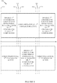
- FIG. 5 illustrates an exemplary timeline 500 showing operations for comparing execution of a plurality of processing systems of a lockstep computing system (e.g., computing device 301 shown in Figure 3 ), according to of the present disclosure.
- processing cores of a processor of a lockstep computing system are operating in lockstep.
- the computing device disables a first comparator while the cores remain operating in lockstep and a second comparator is active and verifying that the cores are in lockstep, with no faults detected.
- the diagnosis of the first comparator is complete and the computing device enables the first comparator.
- both of the first and the second comparator are active, checking that the processing cores are operating in lockstep with no faults.
- the computing device disables the second comparator while the cores remain operating in lockstep and the first comparator is active and verifying that the cores are in lockstep, with no faults detected.
- the diagnosis of the second comparator is complete and the computing device enables the second comparator.
- both of the first and the second comparator are active, checking that the processing cores are operating in lockstep with no faults.
- the computing device disables the first comparator while the cores remain operating in lockstep and the second comparator is active and verifying that the cores are in lockstep, with no faults detected.
- the operations at 570 may be a duplicate of the operations at 510, with the computing device continuing to operate in a continuing cycle of disabling and checking each comparator in turn while the other comparator and the processing cores remain active.
- the timeline 500 illustrates some advantages that an embodiment of the present disclosure may have over computing systems using previously known techniques.
- One advantage may be that, because the processing systems (e.g., cores) are not idle while a diagnosis program is run on a comparator, the diagnosis program is not required to complete operation in less time than an idle time duration constraint of the lockstep computing system, unlike the technique associated with the timeline shown in Figure 2A .
- Another advantage may be that there are no times that the processing systems (e.g., cores) of the computing device are not being verified by at least one comparator, unlike the technique associated with the timeline shown in Figure 2B .
- a computing device may have a fail-operational capability. That is, even after a failure has been found in a comparator circuit, the computing device may continue to safely operate with the cores operating in lockstep and the operations of the cores being verified by another comparator circuit that did not suffer a failure.
- the table below illustrates various operational modes that a computing device may have, based on the status of comparators of the computing device. 1 st Comparator status 2 nd Comparator status Computing device operational mode ON ON SAFE ON DIAGNOSIS SAFE DIAGNOSIS ON SAFE ON FAILED FAIL-OPERATIONAL FAILED ON FAIL-OPERATIONAL
- a system e.g., an automobile, a UAV
- a computing device having a fail-operational mode may allow the system to operate safely after detecting a failure in comparator logic. Continued operation in the fail-operational mode may allow time for replacement of a failed component and/or time to reach a service center, where the system may be repaired.
- FIG. 6 is a block diagram illustrating a computing device 601 configured to operate according to aspects of the present disclosure.
- the computing device 601 may be connected to other computing devices via a network 630.
- the network 630 may be a telecommunications network and/or a wide area network (WAN).
- the computing device 601 may be any type of computing device configured to operate with cores in lockstep according to aspects of the present disclosure, including, without limitation, a desktop computer, a server, a laptop computer, a tablet computer, an ADAS, and a UAV control system.
- the computing device 601 generally includes a processor 610 that includes two processing cores 612a, 612b, and two comparator circuits 614a, 614b.
- the processing cores 612 are connected with the comparator circuits 614, each of which may compare the activity of the processing cores 612.
- a second comparator circuit 614b of computing device 601 may duplicate a subset of functionality of a first comparator circuit 614a, while not duplicating all of the functionality of the first comparator circuit.
- the second comparator circuit may verify outputs of processing cores 612a and 612b that affect outputs of the computing device to a controlled system (e.g., an automobile, a UAV) while not verifying accesses to memory (e.g., L1 cache, L2 cache) and other components.
- a computing device may be referred to as having "smart" redundancy.
- a computing device may be configured such that all outputs to a controlled system traverse an advanced extensible interface (AXI) bus and/or an accelerator coherency port (ACP) bus.
- the computing device may have a first comparator circuit that verifies all outputs of the processing systems and a second comparator circuit that verifies outputs from the processing systems on the AXI and ACP buses, but not other outputs from the processing systems.
- the comparator circuits 614 are connected via a bus 620 to a memory 608, an optional network interface device 618, a storage 609, an input device 622, and an output device 624.
- the comparator circuit 614a may compare the outputs of the processing cores 612 to ensure that the processing cores 612 are operating in lockstep.
- the comparator circuit 614b may compare outputs of the processing cores to the controlled system.
- the computing device 601 generally operates according to an operating system (not shown). As above, any operating system supporting the functions disclosed herein may be used.
- the network interface device 618 may be any type of network communications device allowing the computing device 601 to communicate with other computing devices via the network 630.
- computing device 601 is shown with a single processor with multiple cores, the disclosure is not so limited, and aspects of the present disclosure may be practiced in a computing device with a plurality of single-core processors and/or in a computing device with a plurality of multi-core processors.
- “comparator circuit” may refer to one or more components of a processor useful for comparing operations of cores of the processor, one or more components of a computing device separate from a processor and useful for comparing operations of cores of the processor, one or more components of a computing device useful for comparing operations of a plurality of processors (e.g., in a multi-processor computing device), or one or more processors useful for comparing operations of a plurality of other processors.
- a computing device having a first comparator circuit and a second comparator circuit that duplicates a subset of functionality of the first comparator circuit may have a fail-operational capability, as previously described. That is, even after a failure has been found in the second comparator circuit, the computing device may continue to safely operate with the cores operating in lockstep and the operations of the cores being verified by the first comparator circuit, similar to above. And, even after a failure has been found in the first comparator circuit, the computing device may continue to safely operate with the outputs to the controlled system (e.g., an automobile) being verified by the second comparator circuit.
- the controlled system e.g., an automobile
- a computing device having a first comparator circuit and a second comparator circuit that duplicates a subset of functionality of the first comparator circuit may have lower complexity and/or cost less than a computing device having first and second comparator circuits that are duplicates of each other.
- a computing device having a first comparator circuit and a second comparator circuit may enable routine checking of components (e.g., comparator circuits) of a lockstep computing system without requiring a time period of inactivity for the computing device.
- a first comparator circuit of a computing device may be checked by a diagnosis program while the computing system remains active and a second comparator verifies that processing systems of the computing system are operating in lockstep.
- the foregoing disclosed devices and functionalities may be designed and configured into computer files (e.g. RTL, GDSII, GERBER, etc.) stored on computer readable media. Some or all such files may be provided to fabrication handlers who fabricate devices based on such files. Resulting products include semiconductor wafers that are then cut into semiconductor die and packaged into a semiconductor chip. Some or all such files may be provided to fabrication handlers who configure fabrication equipment using the design data to fabricate the devices described herein.
- computer files e.g. RTL, GDSII, GERBER, etc.
- Resulting products formed from the computer files include semiconductor wafers that are then cut into semiconductor die (e.g., the processor 101) and packaged, and may be further integrated into products including, but not limited to, mobile phones, smart phones, laptops, netbooks, tablets, ultrabooks, desktop computers, digital video recorders, set-top boxes, servers, and any other devices where integrated circuits are used.
- semiconductor die e.g., the processor 101
- Resulting products formed from the computer files include semiconductor wafers that are then cut into semiconductor die (e.g., the processor 101) and packaged, and may be further integrated into products including, but not limited to, mobile phones, smart phones, laptops, netbooks, tablets, ultrabooks, desktop computers, digital video recorders, set-top boxes, servers, and any other devices where integrated circuits are used.
- the computer files form a design structure including the circuits described above and shown in the Figures in the form of physical design layouts, schematics, a hardware-description language (e.g., Verilog, VHDL, etc.).
- design structure may be a text file or a graphical representation of a circuit as described above and shown in the Figures.
- Design process preferably synthesizes (or translates) the circuits described below into a netlist, where the netlist is, for example, a list of wires, transistors, logic gates, control circuits, I/O, models, etc. that describes the connections to other elements and circuits in an integrated circuit design and recorded on at least one of machine readable medium.
- the medium may be a storage medium such as a CD, a compact flash, other flash memory, or a hard-disk drive.
- the hardware, circuitry, and method described herein may be configured into computer files that simulate the function of the circuits described above and shown in the Figures when executed by a processor. These computer files may be used in circuitry simulation tools, schematic editors, or other software applications.
- a phrase referring to "at least one of' a list of items refers to any combination of those items, including single members.
- "at least one of: a, b, or c" is intended to cover a, b, c, a-b, a-c, b-c, and a-b-c, as well as any combination with multiples of the same element (e.g., a-a, a-a-a, a-a-b, a-a-c, a-b-b, a- c-c, b-b, b-b-b, b-b-c, c-c, and c-c-c or any other ordering of a, b, and c ) .
Landscapes
- Engineering & Computer Science (AREA)
- Theoretical Computer Science (AREA)
- General Engineering & Computer Science (AREA)
- Quality & Reliability (AREA)
- Physics & Mathematics (AREA)
- General Physics & Mathematics (AREA)
- Computer Hardware Design (AREA)
- Hardware Redundancy (AREA)
Claims (15)
- Ein Verfahren (400) zum Vergleichen einer Ausführung einer Vielzahl von Verarbeitungssystemen einer Einrichtung, das Folgendes aufweist:Vergleichen (410) einer Ausführung eines Programms auf einem ersten Verarbeitungssystem der Vielzahl von Verarbeitungssystemen und einer Ausführung des Programms auf einem zweiten Verarbeitungssystem der Vielzahl von Verarbeitungssystemen unter Verwendung einer ersten Vergleichselementschaltung;Vergleichen (420) der Ausführung des Programms auf dem ersten Verarbeitungssystem und der Ausführung des Programms auf dem zweiten Verarbeitungssystem unter Verwendung einer zweiten Vergleichselementschaltung; und wobei das Verfahren gekennzeichnet ist durchDurchführen (430) eines Diagnoseprogramms auf der zweiten Vergleichselementschaltung, während das Vergleichen unter Verwendung der ersten Vergleichselementschaltung stattfindet.
- Verfahren nach Anspruch 1, das weiter Folgendes aufweist:
Durchführen des Diagnoseprogramms oder eines anderen Diagnoseprogramms auf der ersten Vergleichselementschaltung, während das Vergleichen unter Verwendung der zweiten Vergleichselementschaltung stattfindet. - Verfahren nach Anspruch 1, das weiter Folgendes aufweist:Deaktivieren der zweiten Vergleichselementschaltung vor Durchführen des Diagnoseprogramms; undAktivieren der zweiten Vergleichselementschaltung nachfolgend auf das Durchführen des Diagnoseprogramms.
- Verfahren nach Anspruch 1, wobei das Vergleichen der Ausführung des Programms auf dem ersten Verarbeitungssystem und der Ausführung des Programms auf dem zweiten Verarbeitungssystem Vergleichen von ersten Werten aufweist, die durch das erste Verarbeitungssystem in einen Speicher geschrieben werden, mit zweiten Werten, die durch das zweite Verarbeitungssystem in den Speicher geschrieben werden.
- Verfahren nach Anspruch 1, wobei das Vergleichen der Ausführung des Programms auf dem ersten Verarbeitungssystem und der Ausführung des Programms auf dem zweiten Verarbeitungssystem Vergleichen erster Werte aufweist, die über einen oder mehrere Busse durch das erste Verarbeitungssystem ausgegeben werden mit zweiten Werten, die über einen oder mehrere Busse durchaus zweite Verarbeitungssystem ausgegeben werden.
- Verfahren nach Anspruch 5, wobei der eine oder die mehreren Busse wenigstens eines von einem AXI-Bus (AXI = advanced extensible interface) oder einem ACP-Bus (ACP = accelerator coherency port) aufweist.
- Verfahren nach Anspruch 1, wobei:das Vergleichen der Ausführung des Programms auf dem ersten Verarbeitungssystem und der Ausführung des Programms auf dem zweiten Verarbeitungssystem unter Verwendung der ersten Vergleichselementschaltung Vergleichen erster Werte aufweist, die durch das erste Verarbeitungssystem ausgegeben werden, mit zweiten Werten, die durch das zweite Verarbeitungssystem ausgegeben werden; unddas Vergleichen der Ausführung des Programms auf dem ersten Verarbeitungssystem und der Ausführung des Programms auf dem zweiten Verarbeitungssystem unter Verwendung der zweiten Vergleichselementschaltung Vergleichen dritter Werte aufweist, die durch das erste Verarbeitungssystem ausgegeben werden, die sich von den ersten Werten unterscheiden, mit vierten Werten, die durch das zweite Verarbeitungssystem ausgegeben werden, die sich von den zweiten Werten unterscheiden.
- Verfahren nach Anspruch 1, wobei:das erste Verarbeitungssystem einen ersten Kern eines Multi-Core- bzw. Mehrkernprozessors aufweist; unddas zweite Verarbeitungssystem einen zweiten Kern des Mehrkernprozessors aufweist.
- Verfahren nach Anspruch 1, wobei:das erste Verarbeitungssystem einen ersten Prozessor der Einrichtung aufweist; unddas zweite Verarbeitungssystem einen zweiten Prozessor der Einrichtung aufweist.
- Verfahren nach Anspruch 1, wobei das Diagnoseprogramm einen Fehler in der zweiten Vergleichselementschaltung detektiert, und das Verfahren weiter Folgendes aufweist:
Ausgeben einer Anzeige, dass die Einrichtung den Fehler hat und sicher arbeitet. - Verfahren nach Anspruch 1, wobei:das Vergleichen der Ausführung des Programms auf dem ersten Verarbeitungssystem und der Ausführung des Programms auf dem zweiten Verarbeitungssystem unter Verwendung der ersten Vergleichselementschaltung Vergleichen von Ausgaben von dem ersten Verarbeitungssystem und dem zweiten Verarbeitungssystem aufweist, die eine andere Einrichtung steuern; unddas Vergleichen der Ausführung des Programms auf dem ersten Verarbeitungssystem und der Ausführung des Programms auf dem zweiten Verarbeitungssystem unter Verwendung der zweiten Vergleichselementschaltung Vergleichen der Ausgaben von dem ersten Verarbeitungssystem und dem zweiten Verarbeitungssystem aufweist, die die andere Einrichtung steuern, und Vergleichen anderer Ausgaben von dem ersten Verarbeitungssystem mit entsprechenden anderen Ausgaben von dem zweiten Verarbeitungssystem.
- Eine Vorrichtung (301), die Folgendes aufweist:ein erstes Verarbeitungssystem (312a);ein zweites Verarbeitungssystem (312b);eine erste Vergleichselementschaltung (314a), die betreibbar ist zum Vergleichen einer Ausführung eines Programms auf dem ersten Verarbeitungssystem und einer Ausführung des Programms auf dem zweiten Verarbeitungssystem; undeine zweite Vergleichsschaltung (314b), die betreibbar ist zum Vergleichen der Ausführung des Programms auf dem ersten Verarbeitungssystem und der Ausführung des Programms auf dem zweiten Verarbeitungssystem und zum Durchführen eines Diagnoseprogramms, während die erste Vergleichselementschaltung die Ausführung des Programms auf dem ersten Verarbeitungssystem und die Ausführung des Programms auf dem zweiten Verarbeitungssystem vergleicht.
- Vorrichtung nach Anspruch 12, wobei die erste Vergleichselementschaltung betreibbar ist zum Durchführen des Diagnoseprogramms oder eines anderen Diagnoseprogramms, während die zweite Vergleichselementschaltung die Ausführung des Programms auf dem ersten Verarbeitungssystem und die Ausführung des Programms auf dem zweiten Verarbeitungssystem vergleicht.
- Vorrichtung nach Anspruch 12, wobei:wenigstens eines von dem ersten Verarbeitungssystem, dem zweiten Verarbeitungssystem, der ersten Vergleichselementschaltung und der zweiten Vergleichselementschaltung betreibbar ist zum Detektieren eines Fehlers in der zweiten Vergleichselementschaltung basierend darauf, dass die zweite Vergleichselementschaltung das Diagnoseprogramms durchführt; undwenigstens eines von dem ersten Verarbeitungssystem und dem zweiten Verarbeitungssystem betreibbar ist zum Ausgeben einer Anzeige, dass die Vorrichtung den Fehler hat und sicher arbeitet.
- Ein nicht transitorisches computerlesbares Medium, das Instruktionen aufweist, wobei die Instruktionen, wenn sie durch ein oder mehrere Verarbeitungssysteme ausgeführt werden, das eine oder die mehreren Verarbeitungssysteme veranlassen zum Durchführen eines Verfahrens nach einem der Ansprüche 1 bis 11.
Applications Claiming Priority (2)
| Application Number | Priority Date | Filing Date | Title |
|---|---|---|---|
| US15/410,271 US10331532B2 (en) | 2017-01-19 | 2017-01-19 | Periodic non-intrusive diagnosis of lockstep systems |
| PCT/US2017/065685 WO2018136169A1 (en) | 2017-01-19 | 2017-12-12 | Periodic non-intrusive diagnosis of lockstep systems |
Publications (2)
| Publication Number | Publication Date |
|---|---|
| EP3555748A1 EP3555748A1 (de) | 2019-10-23 |
| EP3555748B1 true EP3555748B1 (de) | 2020-05-13 |
Family
ID=60915647
Family Applications (1)
| Application Number | Title | Priority Date | Filing Date |
|---|---|---|---|
| EP17823301.1A Active EP3555748B1 (de) | 2017-01-19 | 2017-12-12 | Periodische nichtintrusive diagnose von gleichschrittsystemen |
Country Status (7)
| Country | Link |
|---|---|
| US (1) | US10331532B2 (de) |
| EP (1) | EP3555748B1 (de) |
| KR (1) | KR102016004B1 (de) |
| CN (1) | CN110140112B (de) |
| SG (1) | SG11201905068VA (de) |
| TW (1) | TWI686695B (de) |
| WO (1) | WO2018136169A1 (de) |
Families Citing this family (9)
| Publication number | Priority date | Publication date | Assignee | Title |
|---|---|---|---|---|
| US11424621B2 (en) | 2020-01-28 | 2022-08-23 | Qualcomm Incorporated | Configurable redundant systems for safety critical applications |
| US11281554B2 (en) * | 2020-03-17 | 2022-03-22 | Samsung Electronics Co., Ltd. | System and method for in-memory computation |
| CN112596916A (zh) * | 2021-03-03 | 2021-04-02 | 上海励驰半导体有限公司 | 双核锁步错误恢复系统及方法 |
| DE102021211709A1 (de) * | 2021-10-18 | 2023-04-20 | Robert Bosch Gesellschaft mit beschränkter Haftung | Datenverarbeitungsnetzwerk zur Datenverarbeitung |
| CN114091380A (zh) * | 2021-11-18 | 2022-02-25 | 上海励驰半导体有限公司 | 一种基于lockstep设计的异常检测方法及系统 |
| CN115372710B (zh) * | 2022-10-21 | 2024-02-06 | 西安创联电气科技(集团)有限责任公司 | 一种电阻自动测试装置 |
| US12455799B2 (en) * | 2023-06-16 | 2025-10-28 | Qualcomm Incorporated | Explicit lockstep for functional safety |
| WO2025226795A1 (en) * | 2024-04-23 | 2025-10-30 | Microchip Technology Incorporated | Apparatus and method for fault detection in a dual core lockstep microcontroller |
| GB2641394A (en) * | 2024-05-30 | 2025-12-03 | Imagination Tech Ltd | Processing system configured to process protected tasks |
Family Cites Families (19)
| Publication number | Priority date | Publication date | Assignee | Title |
|---|---|---|---|---|
| US5838894A (en) * | 1992-12-17 | 1998-11-17 | Tandem Computers Incorporated | Logical, fail-functional, dual central processor units formed from three processor units |
| US6862693B2 (en) * | 2001-04-13 | 2005-03-01 | Sun Microsystems, Inc. | Providing fault-tolerance by comparing addresses and data from redundant processors running in lock-step |
| US7392426B2 (en) * | 2004-06-15 | 2008-06-24 | Honeywell International Inc. | Redundant processing architecture for single fault tolerance |
| JP4356634B2 (ja) | 2005-03-23 | 2009-11-04 | 日本電気株式会社 | 故障診断回路とこの故障診断回路を備えた情報処理装置、故障診断システム及び故障診断プログラム |
| DE102005037246A1 (de) * | 2005-08-08 | 2007-02-15 | Robert Bosch Gmbh | Verfahren und Vorrichtung zur Steuerung eines Rechnersystems mit wenigstens zwei Ausführungseinheiten und einer Vergleichseinheit |
| US8010846B1 (en) | 2008-04-30 | 2011-08-30 | Honeywell International Inc. | Scalable self-checking processing platform including processors executing both coupled and uncoupled applications within a frame |
| US7886195B2 (en) * | 2008-05-05 | 2011-02-08 | Infineon Technologies Ag | Apparatus, system, and method of efficiently utilizing hardware resources for a software test |
| JP5509568B2 (ja) * | 2008-10-03 | 2014-06-04 | 富士通株式会社 | コンピュータ装置、プロセッサ診断方法、及びプロセッサ診断制御プログラム |
| CN101794271B (zh) * | 2010-03-31 | 2012-05-23 | 华为技术有限公司 | 多核内存一致性的实现方法和装置 |
| US8937622B2 (en) * | 2010-09-20 | 2015-01-20 | Qualcomm Incorporated | Inter-processor communication techniques in a multiple-processor computing platform |
| US8941655B2 (en) * | 2011-09-07 | 2015-01-27 | Qualcomm Incorporated | Memory copy engine for graphics processing |
| US8819485B2 (en) * | 2012-03-12 | 2014-08-26 | Infineon Technologies Ag | Method and system for fault containment |
| EP2813949B1 (de) | 2013-06-11 | 2019-08-07 | ABB Schweiz AG | Mehrkernprozessorfehlererkennung für sicherheitskritische softwareanwendungen |
| US9223565B2 (en) * | 2013-10-16 | 2015-12-29 | Google Inc. | Rendering interface objects defined by a separate application |
| JP2015222467A (ja) * | 2014-05-22 | 2015-12-10 | ルネサスエレクトロニクス株式会社 | マイクロコントローラ及びそれを用いた電子制御装置 |
| JP6360387B2 (ja) * | 2014-08-19 | 2018-07-18 | ルネサスエレクトロニクス株式会社 | プロセッサシステム、エンジン制御システム及び制御方法 |
| US9823983B2 (en) * | 2014-09-25 | 2017-11-21 | Nxp Usa, Inc. | Electronic fault detection unit |
| US10002056B2 (en) * | 2015-09-15 | 2018-06-19 | Texas Instruments Incorporated | Integrated circuit chip with cores asymmetrically oriented with respect to each other |
| US10089194B2 (en) * | 2016-06-08 | 2018-10-02 | Qualcomm Incorporated | System and method for false pass detection in lockstep dual core or triple modular redundancy (TMR) systems |
-
2017
- 2017-01-19 US US15/410,271 patent/US10331532B2/en active Active
- 2017-12-12 SG SG11201905068VA patent/SG11201905068VA/en unknown
- 2017-12-12 WO PCT/US2017/065685 patent/WO2018136169A1/en not_active Ceased
- 2017-12-12 KR KR1020197020703A patent/KR102016004B1/ko active Active
- 2017-12-12 TW TW106143515A patent/TWI686695B/zh active
- 2017-12-12 EP EP17823301.1A patent/EP3555748B1/de active Active
- 2017-12-12 CN CN201780082244.0A patent/CN110140112B/zh active Active
Non-Patent Citations (1)
| Title |
|---|
| None * |
Also Published As
| Publication number | Publication date |
|---|---|
| EP3555748A1 (de) | 2019-10-23 |
| CN110140112A (zh) | 2019-08-16 |
| US10331532B2 (en) | 2019-06-25 |
| WO2018136169A1 (en) | 2018-07-26 |
| BR112019014536A2 (pt) | 2020-02-27 |
| TW201830243A (zh) | 2018-08-16 |
| TWI686695B (zh) | 2020-03-01 |
| KR102016004B1 (ko) | 2019-08-29 |
| CN110140112B (zh) | 2020-11-17 |
| US20180203778A1 (en) | 2018-07-19 |
| SG11201905068VA (en) | 2019-08-27 |
| KR20190091554A (ko) | 2019-08-06 |
Similar Documents
| Publication | Publication Date | Title |
|---|---|---|
| US10331532B2 (en) | Periodic non-intrusive diagnosis of lockstep systems | |
| US10576990B2 (en) | Method and device for handling safety critical errors | |
| CN109872150B (zh) | 具有时钟同步操作的数据处理系统 | |
| US10761925B2 (en) | Multi-channel network-on-a-chip | |
| CN105373650B (zh) | 基于aadl的ima动态重构建模方法 | |
| CN109634171B (zh) | 双核双锁步二取二架构及其安全平台 | |
| CN104714459A (zh) | 可编程控制器 | |
| CN115384535B (zh) | 一种车辆功能安全监控系统及方法 | |
| CN111124780B (zh) | 一种UPI Link降速测试方法、系统、终端及存储介质 | |
| US11068337B2 (en) | Data processing apparatus that disconnects control circuit from error detection circuit and diagnosis method | |
| CN103927241B (zh) | 一种软硬件结合的内存避错方法及其装置 | |
| Bellotti et al. | How future automotive functional safety requirements will impact microprocessors design | |
| WO2024205732A1 (en) | Processor-based system employing a safety island architecture for fail-safe operation | |
| US9128838B2 (en) | System and method of high integrity DMA operation | |
| HK40005980B (en) | Periodic non-intrusive diagnosis of lockstep systems | |
| HK40005980A (en) | Periodic non-intrusive diagnosis of lockstep systems | |
| CN105446654B (zh) | 服务器控制方法及机架控制器 | |
| CN114443423B (zh) | 一种cpu与fpga之间相互监控的电路 | |
| BR112019014536B1 (pt) | Método para comparar execução de uma pluralidade de sistemas de processamento de um dispositivo, aparelho e memória legível por computador | |
| US12358648B2 (en) | Control device and rover equipped therewith, control method, and recording medium recorded with program | |
| KR102899319B1 (ko) | 프로세스 검사 장치 및 방법과, 전자 제어 장치 | |
| CN107133186B (zh) | 一种主、从tmc同时与bmc通信方法 | |
| US20260064546A1 (en) | Systems and methods for scalable block-based permanent safety fault tolerance | |
| US11493982B2 (en) | Microcontroller and power management integrated circuit application clustering for safe state management | |
| JP2011081705A (ja) | メモリ制御装置及びメモリ制御装置の制御方法 |
Legal Events
| Date | Code | Title | Description |
|---|---|---|---|
| STAA | Information on the status of an ep patent application or granted ep patent |
Free format text: STATUS: UNKNOWN |
|
| STAA | Information on the status of an ep patent application or granted ep patent |
Free format text: STATUS: THE INTERNATIONAL PUBLICATION HAS BEEN MADE |
|
| PUAI | Public reference made under article 153(3) epc to a published international application that has entered the european phase |
Free format text: ORIGINAL CODE: 0009012 |
|
| STAA | Information on the status of an ep patent application or granted ep patent |
Free format text: STATUS: REQUEST FOR EXAMINATION WAS MADE |
|
| 17P | Request for examination filed |
Effective date: 20190716 |
|
| AK | Designated contracting states |
Kind code of ref document: A1 Designated state(s): AL AT BE BG CH CY CZ DE DK EE ES FI FR GB GR HR HU IE IS IT LI LT LU LV MC MK MT NL NO PL PT RO RS SE SI SK SM TR |
|
| AX | Request for extension of the european patent |
Extension state: BA ME |
|
| GRAP | Despatch of communication of intention to grant a patent |
Free format text: ORIGINAL CODE: EPIDOSNIGR1 |
|
| STAA | Information on the status of an ep patent application or granted ep patent |
Free format text: STATUS: GRANT OF PATENT IS INTENDED |
|
| DAV | Request for validation of the european patent (deleted) | ||
| DAX | Request for extension of the european patent (deleted) | ||
| INTG | Intention to grant announced |
Effective date: 20200102 |
|
| GRAS | Grant fee paid |
Free format text: ORIGINAL CODE: EPIDOSNIGR3 |
|
| GRAA | (expected) grant |
Free format text: ORIGINAL CODE: 0009210 |
|
| STAA | Information on the status of an ep patent application or granted ep patent |
Free format text: STATUS: THE PATENT HAS BEEN GRANTED |
|
| AK | Designated contracting states |
Kind code of ref document: B1 Designated state(s): AL AT BE BG CH CY CZ DE DK EE ES FI FR GB GR HR HU IE IS IT LI LT LU LV MC MK MT NL NO PL PT RO RS SE SI SK SM TR |
|
| REG | Reference to a national code |
Ref country code: GB Ref legal event code: FG4D |
|
| REG | Reference to a national code |
Ref country code: CH Ref legal event code: EP |
|
| REG | Reference to a national code |
Ref country code: DE Ref legal event code: R096 Ref document number: 602017016857 Country of ref document: DE |
|
| REG | Reference to a national code |
Ref country code: AT Ref legal event code: REF Ref document number: 1271159 Country of ref document: AT Kind code of ref document: T Effective date: 20200615 |
|
| REG | Reference to a national code |
Ref country code: CH Ref legal event code: NV Representative=s name: MAUCHER JENKINS PATENTANWAELTE AND RECHTSANWAE, DE |
|
| REG | Reference to a national code |
Ref country code: NL Ref legal event code: FP |
|
| REG | Reference to a national code |
Ref country code: LT Ref legal event code: MG4D |
|
| PG25 | Lapsed in a contracting state [announced via postgrant information from national office to epo] |
Ref country code: PT Free format text: LAPSE BECAUSE OF FAILURE TO SUBMIT A TRANSLATION OF THE DESCRIPTION OR TO PAY THE FEE WITHIN THE PRESCRIBED TIME-LIMIT Effective date: 20200914 Ref country code: IS Free format text: LAPSE BECAUSE OF FAILURE TO SUBMIT A TRANSLATION OF THE DESCRIPTION OR TO PAY THE FEE WITHIN THE PRESCRIBED TIME-LIMIT Effective date: 20200913 Ref country code: SE Free format text: LAPSE BECAUSE OF FAILURE TO SUBMIT A TRANSLATION OF THE DESCRIPTION OR TO PAY THE FEE WITHIN THE PRESCRIBED TIME-LIMIT Effective date: 20200513 Ref country code: FI Free format text: LAPSE BECAUSE OF FAILURE TO SUBMIT A TRANSLATION OF THE DESCRIPTION OR TO PAY THE FEE WITHIN THE PRESCRIBED TIME-LIMIT Effective date: 20200513 Ref country code: LT Free format text: LAPSE BECAUSE OF FAILURE TO SUBMIT A TRANSLATION OF THE DESCRIPTION OR TO PAY THE FEE WITHIN THE PRESCRIBED TIME-LIMIT Effective date: 20200513 Ref country code: NO Free format text: LAPSE BECAUSE OF FAILURE TO SUBMIT A TRANSLATION OF THE DESCRIPTION OR TO PAY THE FEE WITHIN THE PRESCRIBED TIME-LIMIT Effective date: 20200813 Ref country code: GR Free format text: LAPSE BECAUSE OF FAILURE TO SUBMIT A TRANSLATION OF THE DESCRIPTION OR TO PAY THE FEE WITHIN THE PRESCRIBED TIME-LIMIT Effective date: 20200814 |
|
| PG25 | Lapsed in a contracting state [announced via postgrant information from national office to epo] |
Ref country code: BG Free format text: LAPSE BECAUSE OF FAILURE TO SUBMIT A TRANSLATION OF THE DESCRIPTION OR TO PAY THE FEE WITHIN THE PRESCRIBED TIME-LIMIT Effective date: 20200813 Ref country code: HR Free format text: LAPSE BECAUSE OF FAILURE TO SUBMIT A TRANSLATION OF THE DESCRIPTION OR TO PAY THE FEE WITHIN THE PRESCRIBED TIME-LIMIT Effective date: 20200513 Ref country code: LV Free format text: LAPSE BECAUSE OF FAILURE TO SUBMIT A TRANSLATION OF THE DESCRIPTION OR TO PAY THE FEE WITHIN THE PRESCRIBED TIME-LIMIT Effective date: 20200513 Ref country code: RS Free format text: LAPSE BECAUSE OF FAILURE TO SUBMIT A TRANSLATION OF THE DESCRIPTION OR TO PAY THE FEE WITHIN THE PRESCRIBED TIME-LIMIT Effective date: 20200513 |
|
| REG | Reference to a national code |
Ref country code: AT Ref legal event code: MK05 Ref document number: 1271159 Country of ref document: AT Kind code of ref document: T Effective date: 20200513 |
|
| PG25 | Lapsed in a contracting state [announced via postgrant information from national office to epo] |
Ref country code: AL Free format text: LAPSE BECAUSE OF FAILURE TO SUBMIT A TRANSLATION OF THE DESCRIPTION OR TO PAY THE FEE WITHIN THE PRESCRIBED TIME-LIMIT Effective date: 20200513 |
|
| PG25 | Lapsed in a contracting state [announced via postgrant information from national office to epo] |
Ref country code: EE Free format text: LAPSE BECAUSE OF FAILURE TO SUBMIT A TRANSLATION OF THE DESCRIPTION OR TO PAY THE FEE WITHIN THE PRESCRIBED TIME-LIMIT Effective date: 20200513 Ref country code: IT Free format text: LAPSE BECAUSE OF FAILURE TO SUBMIT A TRANSLATION OF THE DESCRIPTION OR TO PAY THE FEE WITHIN THE PRESCRIBED TIME-LIMIT Effective date: 20200513 Ref country code: RO Free format text: LAPSE BECAUSE OF FAILURE TO SUBMIT A TRANSLATION OF THE DESCRIPTION OR TO PAY THE FEE WITHIN THE PRESCRIBED TIME-LIMIT Effective date: 20200513 Ref country code: AT Free format text: LAPSE BECAUSE OF FAILURE TO SUBMIT A TRANSLATION OF THE DESCRIPTION OR TO PAY THE FEE WITHIN THE PRESCRIBED TIME-LIMIT Effective date: 20200513 Ref country code: CZ Free format text: LAPSE BECAUSE OF FAILURE TO SUBMIT A TRANSLATION OF THE DESCRIPTION OR TO PAY THE FEE WITHIN THE PRESCRIBED TIME-LIMIT Effective date: 20200513 Ref country code: DK Free format text: LAPSE BECAUSE OF FAILURE TO SUBMIT A TRANSLATION OF THE DESCRIPTION OR TO PAY THE FEE WITHIN THE PRESCRIBED TIME-LIMIT Effective date: 20200513 Ref country code: SM Free format text: LAPSE BECAUSE OF FAILURE TO SUBMIT A TRANSLATION OF THE DESCRIPTION OR TO PAY THE FEE WITHIN THE PRESCRIBED TIME-LIMIT Effective date: 20200513 Ref country code: ES Free format text: LAPSE BECAUSE OF FAILURE TO SUBMIT A TRANSLATION OF THE DESCRIPTION OR TO PAY THE FEE WITHIN THE PRESCRIBED TIME-LIMIT Effective date: 20200513 |
|
| REG | Reference to a national code |
Ref country code: DE Ref legal event code: R097 Ref document number: 602017016857 Country of ref document: DE |
|
| PG25 | Lapsed in a contracting state [announced via postgrant information from national office to epo] |
Ref country code: SK Free format text: LAPSE BECAUSE OF FAILURE TO SUBMIT A TRANSLATION OF THE DESCRIPTION OR TO PAY THE FEE WITHIN THE PRESCRIBED TIME-LIMIT Effective date: 20200513 Ref country code: PL Free format text: LAPSE BECAUSE OF FAILURE TO SUBMIT A TRANSLATION OF THE DESCRIPTION OR TO PAY THE FEE WITHIN THE PRESCRIBED TIME-LIMIT Effective date: 20200513 |
|
| PLBE | No opposition filed within time limit |
Free format text: ORIGINAL CODE: 0009261 |
|
| STAA | Information on the status of an ep patent application or granted ep patent |
Free format text: STATUS: NO OPPOSITION FILED WITHIN TIME LIMIT |
|
| 26N | No opposition filed |
Effective date: 20210216 |
|
| PG25 | Lapsed in a contracting state [announced via postgrant information from national office to epo] |
Ref country code: MC Free format text: LAPSE BECAUSE OF FAILURE TO SUBMIT A TRANSLATION OF THE DESCRIPTION OR TO PAY THE FEE WITHIN THE PRESCRIBED TIME-LIMIT Effective date: 20200513 |
|
| REG | Reference to a national code |
Ref country code: BE Ref legal event code: MM Effective date: 20201231 |
|
| PG25 | Lapsed in a contracting state [announced via postgrant information from national office to epo] |
Ref country code: IE Free format text: LAPSE BECAUSE OF NON-PAYMENT OF DUE FEES Effective date: 20201212 Ref country code: LU Free format text: LAPSE BECAUSE OF NON-PAYMENT OF DUE FEES Effective date: 20201212 |
|
| PG25 | Lapsed in a contracting state [announced via postgrant information from national office to epo] |
Ref country code: TR Free format text: LAPSE BECAUSE OF FAILURE TO SUBMIT A TRANSLATION OF THE DESCRIPTION OR TO PAY THE FEE WITHIN THE PRESCRIBED TIME-LIMIT Effective date: 20200513 Ref country code: MT Free format text: LAPSE BECAUSE OF FAILURE TO SUBMIT A TRANSLATION OF THE DESCRIPTION OR TO PAY THE FEE WITHIN THE PRESCRIBED TIME-LIMIT Effective date: 20200513 Ref country code: CY Free format text: LAPSE BECAUSE OF FAILURE TO SUBMIT A TRANSLATION OF THE DESCRIPTION OR TO PAY THE FEE WITHIN THE PRESCRIBED TIME-LIMIT Effective date: 20200513 |
|
| PG25 | Lapsed in a contracting state [announced via postgrant information from national office to epo] |
Ref country code: MK Free format text: LAPSE BECAUSE OF FAILURE TO SUBMIT A TRANSLATION OF THE DESCRIPTION OR TO PAY THE FEE WITHIN THE PRESCRIBED TIME-LIMIT Effective date: 20200513 |
|
| PG25 | Lapsed in a contracting state [announced via postgrant information from national office to epo] |
Ref country code: BE Free format text: LAPSE BECAUSE OF NON-PAYMENT OF DUE FEES Effective date: 20201231 |
|
| PG25 | Lapsed in a contracting state [announced via postgrant information from national office to epo] |
Ref country code: SI Free format text: LAPSE BECAUSE OF FAILURE TO SUBMIT A TRANSLATION OF THE DESCRIPTION OR TO PAY THE FEE WITHIN THE PRESCRIBED TIME-LIMIT Effective date: 20200513 |
|
| PGFP | Annual fee paid to national office [announced via postgrant information from national office to epo] |
Ref country code: DE Payment date: 20241111 Year of fee payment: 8 |
|
| PGFP | Annual fee paid to national office [announced via postgrant information from national office to epo] |
Ref country code: GB Payment date: 20241114 Year of fee payment: 8 |
|
| PGFP | Annual fee paid to national office [announced via postgrant information from national office to epo] |
Ref country code: FR Payment date: 20241111 Year of fee payment: 8 |
|
| PGFP | Annual fee paid to national office [announced via postgrant information from national office to epo] |
Ref country code: CH Payment date: 20250101 Year of fee payment: 8 |
|
| PGFP | Annual fee paid to national office [announced via postgrant information from national office to epo] |
Ref country code: NL Payment date: 20251113 Year of fee payment: 9 |